


CSB42WSKBSS
GE CSB42WSKBSS, CSB48WSKBSS, PSB42YSKBSS, PSB48YSKBSS, ZISP420DHASS Installation Guide
...
Installation
Instructions
Side by Side Refrigerators
Design Guide
With Installation Instructions
31-49057-1 5
224D1889P01
10-14 GE
monogram,corn
Safety information
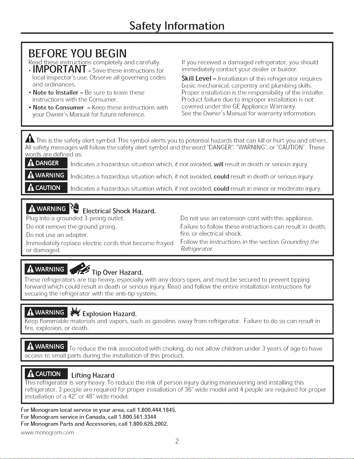
BEFOREYOU BEGIN
Read these instructions completely and carefully.
.IMPORTANT-Savetheseinstructionsfor
local inspector's use. Observe all governing codes
and ordinances.
• Note to Installer - Be sure to leave these
instructions with the Consumer.
• Note to Consumer - Keep these instructions with
your Owner's Manual for future reference.
A This is the safety alert symbol. This symbol alerts you to potential hazards that can kill or hurt you and others.
All safety messages will follow the safety alert symbol and the word "DANGER", "WARNING", or "CAUTION". These
words are defined as:
Indicates a hazardous situation which, if not avoided, will result in death or serious injury.
Indicates a hazardous situation which, if not avoided, could result in death or serious injury.
Indicates a hazardous situation which, if not avoided, could result in minor or moderate injury.
If you received a damaged refrigerator, you should
immediately contact your dealer or builder.
Skill Level - Installation of this refrigerator requires
basic mechanical, carpentry and plumbing skills.
Proper installation is the responsibility of the installer.
Product failure due to improper installation is not
covered under the GE Appliance Warranty.
See the Owner's Manual for warranty information.
__ Electrical Shock Hazard,
Plug into a grounded 3-prong outlet.
Do not remove the ground prong.
Do not use an adapter.
Immediately replace electric cords that become frayed
or damaged.
_Tip Over Hazard.
These refrigerators are top heavy, especially with any doors open, and must be secured to prevent tipping
forward which could result in death or serious injury. Read and follow the entire installation instructions for
securing the refrigerator with the anti-tip system.
_J_' Explosion Hazard.
Keep flammable materials and vapors, such as gasoline, away from refrigerator. Failure to do so can result in
fire, explosion, or death.
To reduce the risk associated with choking, do not allow children under 3 years of age to have
access to small parts during the installation of this product.
Lifting Hazard
This refrigerator is very heavy. To reduce the risk of person injury during maneuvering and installing this
refrigerator, 3 people are required for proper installation of 36" wide model and 4 people are required for proper
installation of a 42" or 48" wide model.
Do not use an extension cord with this appliance.
Failure to follow these instructions can result in death,
fire, or electrical shock.
Follow the instructions in the section Grounding the
Refrigerator.
For Monogram local service in your area, call 1.800.444.1845.
For Monogram service in Canada, call 1.800.561.3344
For Monogram Parts and Accessories, call 1.800.626.2002.
www,monogram,com
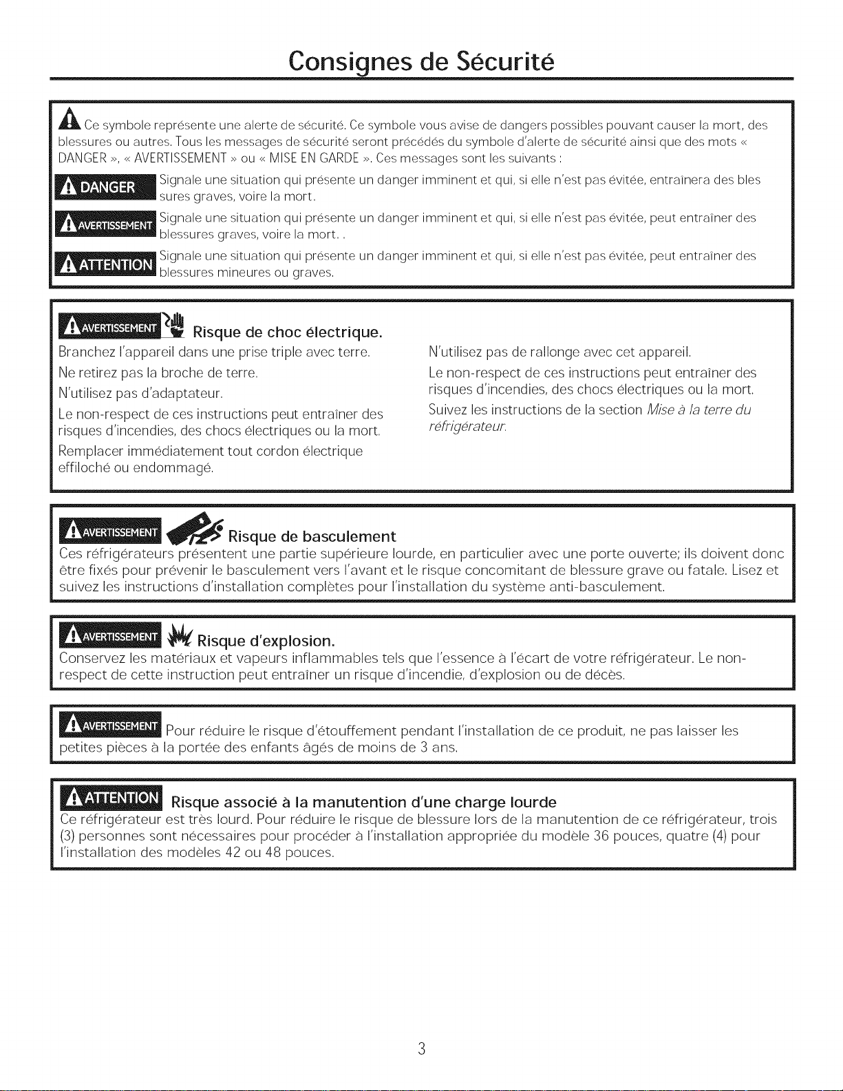
Consignes de Securite
ACe symbole represente une alerte de s6curite, Ce symbole vous avise de dangers possibles pouvant causer la mort, des
blessures ou autres, Tousles messages de s6curite seront prec6d6s du symbole d'alerte de s6curite ainsi que des mots <<
DANGER >>,<<AVERTISSEMENT >>ou <<MISE EN GARDE >>,Ces messages sont les suivants :
Signale une situation qui presente un danger imminent et qui, si elle n'est pas evitee, entrainera des bles
sures graves, voire la mort,
Signale une situation qui presente un danger imminent et qui, si elle n'est pas evitee, peut entrainer des
blessures graves, voire la mort,,
_ ignale une situation qui presente un danger imminent et qui, si elle n'est pas evitee, peut entrainer des
blessures mineures ou graves,
Risque de choc electrique.
Branchez I'appareil dans une prise triple avec terre.
Ne retirez pas la broche de terre.
N'utilisez pas d'adaptateur.
Le non-respect de ces instructions peut entrainer des
risques d'incendies, des chocs electriques ou la mort.
N'utilisez pas de rallonge avec cet appareil.
Le non-respect de ces instructions peut entrainer des
risques d'incendies, des chocs electriques ou la mort.
Suivez les instructions de la section Mise a la terre du
mfrigerateur,
Remplacer immediatement tout cordon electrique
effiloche ou endommage.
_/_ Risque de basculement
Ces r6frigerateurs presentent une partie superieure Iourde, en particulier avec une porte ouverte; ils doivent doric
6tre fixes pour prevenir le basculement vers I'avant et le risque concomitant de blessure grave ou fatale. Lisez et
suivez les instructions d'installation completes pour I'installation du systeme anti-basculement
_( Risque d'explosion.
Conservez les materiaux et vapeurs inflammables tels que I'essence a I%cart de votre refrigerateur. Le non-
respect de cette instruction peut entrainer un risque d'incendie, d'explosion ou de deces.
Pour reduire le risque d%touffement pendant I'installation de ce produit, ne pas laisser les
petites pieces a la portee des enfants 896s de moins de 3 arts.
Risque associe a la manutention d'une charge Iourde
Ce refrig6rateur est tres Iourd. Pour reduire le risque de blessure lots de la manutention de ce refrigGrateur, trois
(3) personnes sont necessaires pour proceder a I'installation appropriee du modele 36 pouces, quatre (4) pour
I'installation des modeles 42 ou 48 pouces.

Contents
Safety
Planning Guide
The Installation Space
Dimensions and Clearances
Customization Basics
3/4" Overlay Panel Dimensions - Flush
1/4" Framed Panel Dimensions- Standard
3/4" Overlay Panel Dimensions - Standard
90 ° Door Swing
130 ° Door Swing
Dispenser Trim
Side Panels
Installation Instructions
Tools, Hardware, Materials
Parts Identification
Grounding the Refrigerator
Step 1. Remove Packaging
Step 2. Move Refrigerator into House
Step 3. Install Water Line
2, 3 Step 4. Household Water Filtration 17
Step 5. Install Side Panels 17
Step 6. Install Case Trim 17
5 Step 7. Anti-Tip Procedure 17-18
5 Step 8. Level Refrigerator 18
6 Step 9. Secure Refrigerator to Cabinetry 18
7 Step 10. Adjust Door Swing 19
8 Step 11. Remove Door Trim 19
9 Step 12. Layout Decorative Door Panels 20-21
10 Step 13. Attach Brackets to Panels 21
11 Step 14. Hang Decorative Door Panels 22
12 Step 15. Layout Decorative Hood Panel 23
13 Step 16. Install Hood Panel 23
Step 17. Adjust Decorative Panels 24-25
Step 18 Replace Trim 25
13 Step 19. Connect Water Supply 26
14 Step 20. Connect Power, Close Grille Panel 26
15 Step 21. Start Icemaker 26
16 Step 22. Install Toekick 27
16 Inspect Final Installation 27
16
Design Guide
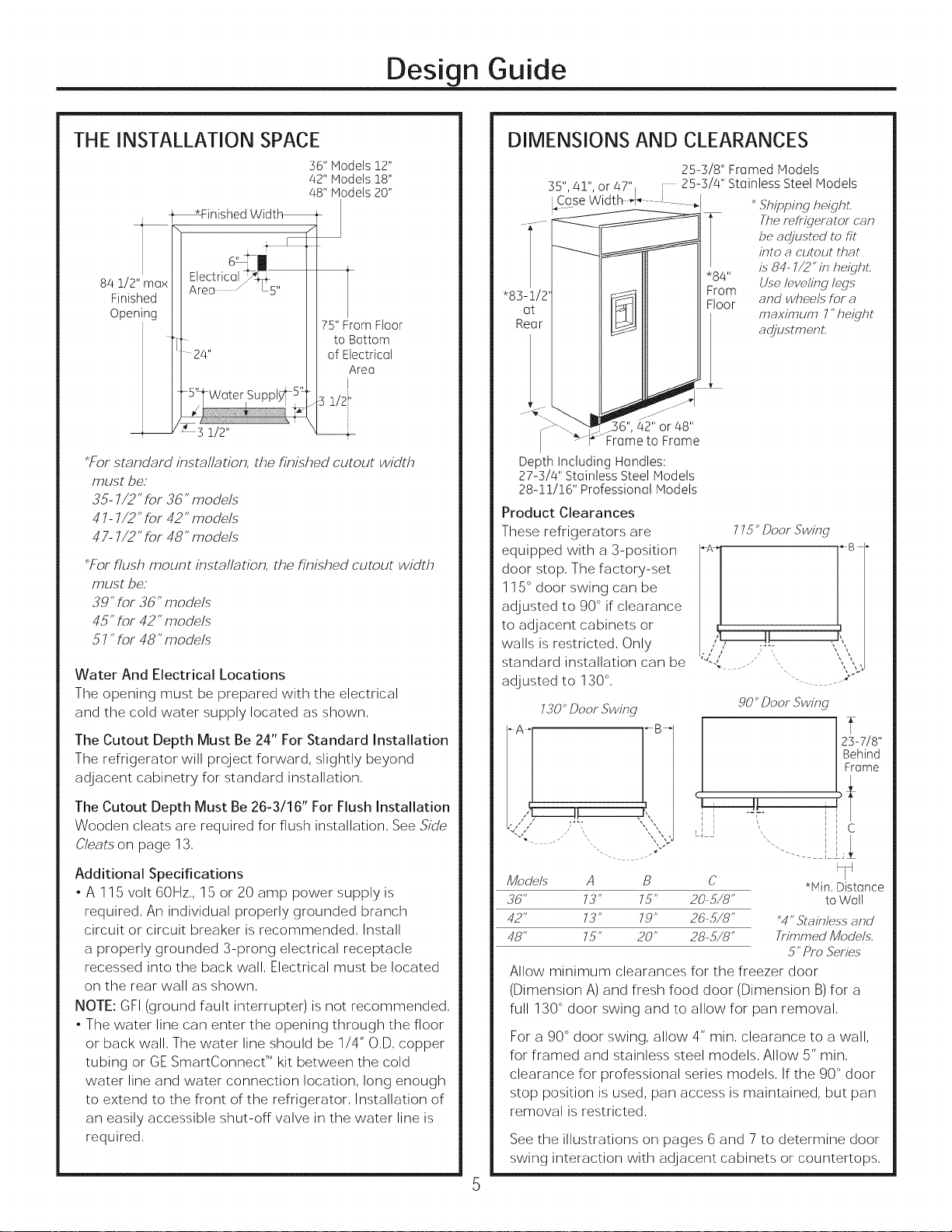
THE INSTALLATION SPACE
36" Models 12"
42" Models 18"
48" Models 20"
84 1/2"max II2 a 'o
Finished II ......
Opening Ill ..... 75'_oFrBOc_oF,Oor
___ y. 1/2'
*For standard installation, the finished cutout width
must be;
35- 7/2" for 36" models
# 7-7/2" for 42" models
47- 7/2" for 48" models
*For flush mount installation, the finished cutout width
must be;
39" for 36" models
45" for 42" models
57 "for 48" models
Water And Electrical Locations
The opening must be prepared with the electrical
and the cold water supply located as shown,
The Cutout Depth Must Be 24" For Standard Installation
The refrigerator will project forward, slightly beyond
adjacent cabinetry for standard installation,
The Cutout Depth Must Be 26-3/16" For Flush Installation
Wooden cleats are required for flush installation, See Side
Cleats on page 13,
Electrical_ 1
2/4" of Electrical
IArea
DIMENSIONS AND CLEARANCES
25-3/8" Framed Models
35", 4!", or 47" 25-3/4" Stainless Steel Models
14CgseWidth-4 .... J......... I
I
"83-1,
at
Rea
42" or 48"
Frame to Frame
Depth Including Handles:
27-3/4" Stainless Steel Models
28-11/16" Professional Models
Product Clearances
These refrigerators are
equipped with a 3-position
door stop, The factory-set
115° door swing can be
adjusted to 90 ° if clearance
to adjacent cabinets or
walls is restricted, Only
standard installation can be
adjusted to 130 °,
730_"Door Swing
i:
i
J8o4 Yherefrigeratorcan
Floor and wheels for a
]
, i 7_L:
LJ J
Shipping height,
be adjusted to fit
into a cutout that
,, is 84- 7/2" in height,
m Useleveling legs
maximum 7"height
adjustment,
775 _"Door Swing
gO_"Door Swing
2_-7/8"
Behind
F;ame
I C
Additional Specifications
. A 115 volt 60Hz,, 15 or 20 amp power supply is
required, An individual properly grounded branch
circuit or circuit breaker is recommended, Install
a properly grounded 3-prong electrical receptacle
recessed into the back wall, Electrical must be located
on the rear wall as shown,
NOTE: GFI (ground fault interrupter)is not recommended,
. The water line can enter the opening through the floor
or back wall, The water line should be 1/4" O,D, copper
tubing or GE SmartConnect TM kit between the cold
water line and water connection location, long enough
to extend to the front of the refrigerator, Installation of
an easily accessible shut-off valve in the water line is
required,
Models A B C *Hin. Distance
36" 73" 75" 20- 5/8" to Walt
42" 73" 79" 26-5/8" _4" Stainless and
48" 75" 20" 28-5/8" Trimmed Models,
5" Pro Series
Allow minimum clearances for the freezer door
(Dimension A) and fresh food door (Dimension B) for a
full 130 ° door swing and to allow for pan removal,
For a 90 ° door swing, allow 4" min, clearance to a wall,
for framed and stainless steel models, Allow 5" min,
clearance for professional series models, If the 90° door
stop position is used, pan access is maintained, but pan
removal is restricted,
See the illustrations on pages 6 and 7 to determine door
swing interaction with adjacent cabinets or countertops,
Design Guide
CUSTOMIZATION BASICS:
Professional Style Stainless Steel Refrigerators
Stainless steel wrapped refrigerators have beveled edges and professional-style handles, These models are shipped ready
for installation,
Stainless Steel Wrapped Refrigerators
Stainless Steel wrapped refrigerators have wrapped doors and grille panel, beveled edges, and tubular stainless steel
handles that coordinate with other Monogram appliances, These models are shipped ready for installation,
Trimmed Refrigerators
Trimmed refrigerators are designed to be customized with decorative panels, Field installed custom door and grille panels
are required,
Optional Accessory Kits
ZKHSS2: Monogram Tubular Stainless Steel handles
designed to fit 3/4" overlay panels,
ZKHPSSI: Professional Tubular Stainless Steel handles
designed to fit 3/4" overlay panels, Kit includes one
handle, Order 2 kits for side-by-side refrigerator models
from your Monogram supplier
ZTK36SSH: Trim Kit for 36" Side-by-side refrigerator using
custom panels for standard installation,
ZTK42SSH: Trim kit for 42" Side-by-side refrigerator using
custom panels for standard installation,
ZTK48SSH: Trim kit for 48" Side-by-side refrigerator using
custom panels for standard installation,
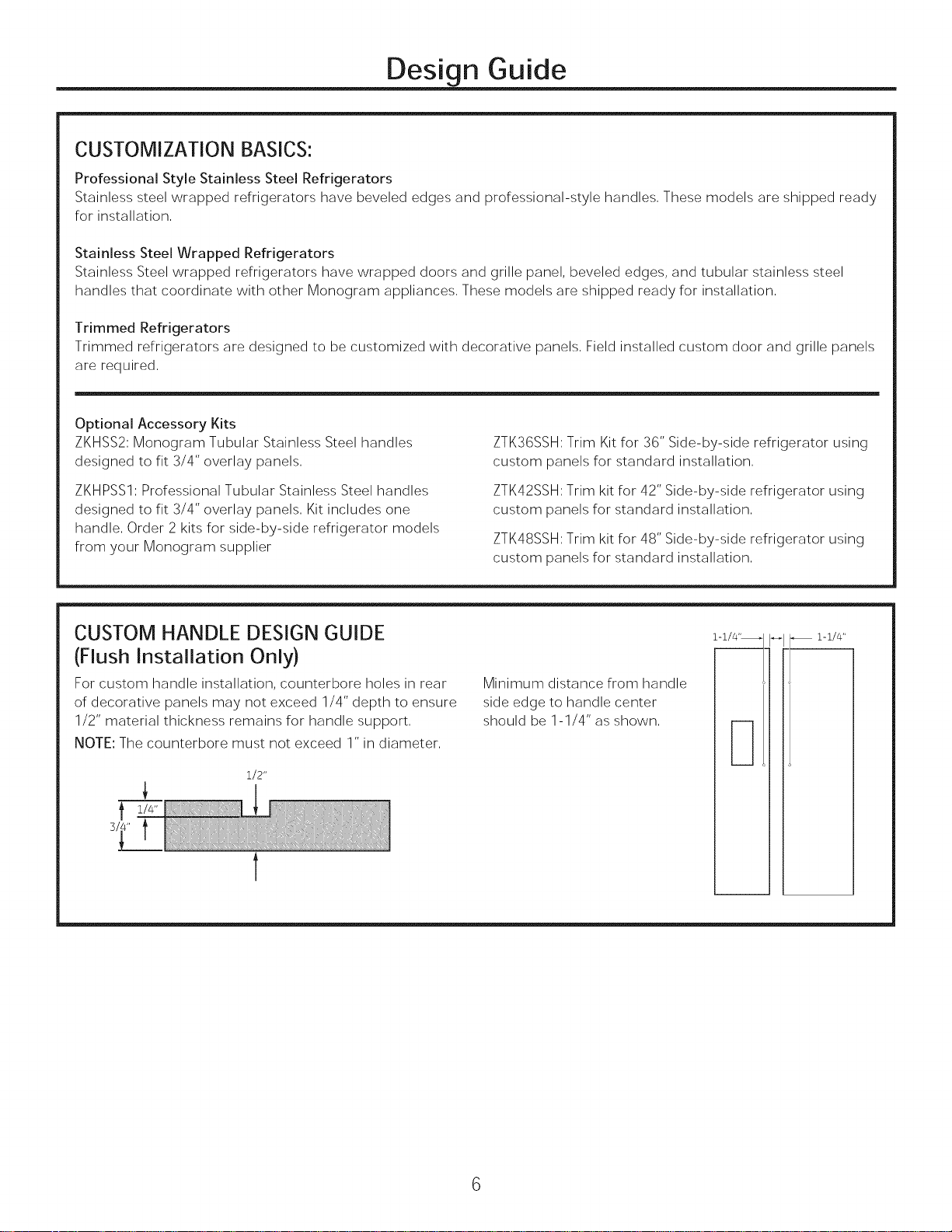
CUSTOM HANDLE DESIGN GUIDE
(Flush Installation Only)
For custom handle installation, counterbore holes in rear
of decorative panels may not exceed 1/4" depth to ensure
1/2" material thickness remains for handle support,
NOTE: The counterbore must not exceed 1" in diameter,
1/2"
t
1-1/4"
Minimum distance from handle
side edge to handle center
should be 1-1/4" as shown,
Design Guide
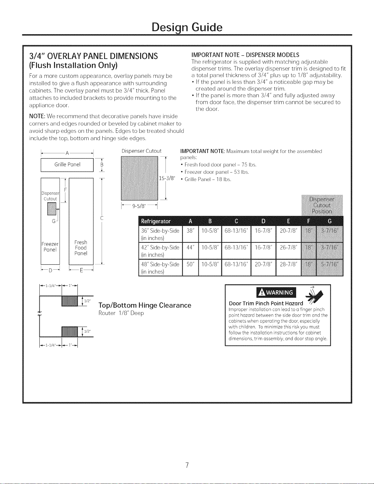
3/4" OVERLAY PANEL DIMENSIONS
(Flush Installation Only)
For a more custom appearance, overlay panels may be
installed to give a flush appearance with surrounding
cabinets, The overlay panel must be 3/4" thick, Panel
attaches to included brackets to provide mounting to the
appliance door,
NOTE: We recommend that decorative panels have inside
corners and edges rounded or beveled by cabinet maker to
avoid sharp edges on the panels. Edges to be treated should
include the top, bottom and hinge side edges.
Dispenser Cutout
Grille Panel
15-]18"
F
Dispense_ LCutout
36" Side-by-Side 38" 10-5/8" 68-13/16" 16-7/8" 20-7/8"
Freezer Fresh
Panel Food
Panel
I-_ D_1 I_E_
(in inches)
42" Side-by-Side 44" 10-5/8" 68-13/16" 16-7/8" 26-7/8" q_'i!Ll!t*
(in inches) i
48"Side-by-Side 50" 10-5/8" 68-13/16" 20-7/8" 28-7/8"
(in inches)
IMPORTANT NOTE - DISPENSER MODELS
The refrigerator is supplied with matching adjustable
dispenser trims. The overlay dispenser trim is designed to fit
a total panel thickness of 3/4" plus up to 1/8" adjustability.
. If the panel is less than 3/4" a noticeable gap may be
created around the dispenser trim.
. If the panel is more than 3/4" and fully adjusted away
from door face, the dispenser trim cannot be secured to
the door.
IMPORTANT NOTE: Maximum total weight for the assembled
panels:
, Fresh food door panel- 75 Ibs,
, Freezer door panel- 53 Ibs,
, Grille Panel- 18 Ibs,
1/2"
Top/Bottom Hinge Clearance
Router 1/8" Deep
1/2"
f>
Door Trim Pinch Point Hazard
Improperinstallationcan leadto a finger pinch
pointhazardbetweenthe sidedoortrim and the
cabinetswhen operatingthe door,especially
with children. Tominimizethisriskyou must
followthe installationinstructionsfor cabinet
dimensions,trim assembly,anddoor stopangle.
Design Guide
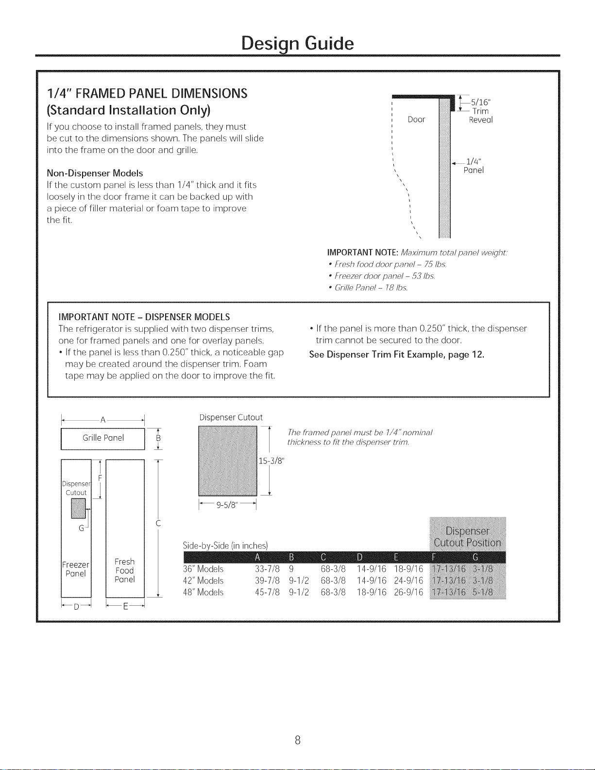
1/4" FRAMED PANEL DIMENSIONS
(Standard Installation Only)
If you choose to install framed panels, they must
be cut to the dimensions shown, The panels will slide
into the frame on the door and grille,
Non-Dispenser Models
If the custom panel is less than 1/4" thick and it fits
loosely in the door frame it can be backed up with
a piece of filler material or foam tape to improve
the fit,
IMPORTANT NOTE - DISPENSER MODELS
The refrigerator is supplied with two dispenser trims,
one for framed panels and one for overlay panels,
, If the panel is less than 0,250" thick, a noticeable gap
may be created around the dispenser trim, Foam
tape may be applied on the door to improve the fit,
"175!!6"
Door
IMPORTANT NOTE: M_ximum total panel weight;
• Fresh food door panel - 75 Ibs,
• Freezer door panel - 53 Ibs,
• Grille Panel - 78 Ibs,
, If the panel is more than 0,250" thick, the dispenser
trim cannot be secured to the door,
See Dispenser Trim Fit Example, page 12.
,LTrim
Reveal
Panel
..............1/4"
Grille Panel
F
Cutout
Dispense_ L
Freezer Fresh
Panel Food
_D -_ _E_
Panel
Dispenser Cutout
The #amed panel must be 7/4" nominal
thickness to fit the dispenser trim,
15-318"
Side-by-Side (in inches)
36"Models 33-7/8 9 68-3/8 14-9/16 18-9/16
42"Models 39-7/8 9-1/2 68-3/8 14-9/16 24-9/16
48"Models 45-7/8 9-1/2 68-3/8 18-9/16 26-9/16
Design Guide
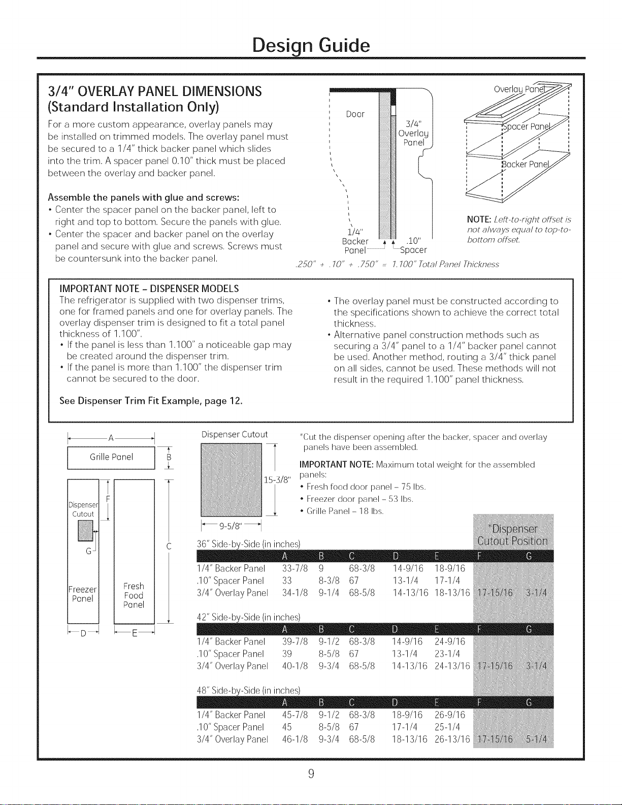
3/4" OVERLAY PANEL DIMENSIONS
(Standard Installation Only)
For a more custom appearance, overlay panels may
be installed on trimmed models, The overlay panel must
be secured to a 1/4" thick backer panel which slides
into the trim, A spacer panel 0,10" thick must be placed
between the overlay and backer panel,
Assemble the panels with glue and screws:
, Center the spacer panel on the backer panel, left to
right and top to bottom, Secure the panels with glue,
, Center the spacer and backer panel on the overlay
panel and secure with glue and screws, Screws must
be countersunk into the backer panel,
IMPORTANT NOTE - DISPENSER MODELS
The refrigerator is supplied with two dispenser trims,
one for framed panels and one for overlay panels, The
overlay dispenser trim is designed to fit a total panel
thickness of 1,100",
, If the panel is less than 1,100" a noticeable gap may
be created around the dispenser trim,
, If the panel is more than 1,100" the dispenser trim
cannot be secured to the door,
Door
L
NOTE: Left-to-right offset is
not cllwc_y,sequcfl to top-to-
Backer .
bottom of Fset,
Panel.......................Spacer
,250" + ,70" + ,750" 7,7OO"Tote_/Pnnel Thickness
, The overlay panel must be constructed according to
the specifications shown to achieve the correct total
thickness,
, Alternative panel construction methods such as
securing a 3/4" panel to a 1/4" backer panel cannot
be used, Another method, routing a 3/4" thick panel
on all sides, cannot be used, These methods will not
result in the required 1,100" panel thickness,
OverlaL
£ackerPanel
See Dispenser Trim Fit Example, page 12.
A
Dispenser Cutout
Grille Panel B
F
Cutout
Dispenser
I_ 9-5/8" _1
36"Side-by-Side(ininches)
1/4" BackerPanel 33-7/8 9 68-3/8 14-9/16 18-9/16
Freezer Fresh
Panel Food
-- m
Panel
_D_4 _E_
,10"SpacerPanel 33 8-3/8 67 13-1/4 17-1/4
3/4"OverlayPanel 34-1/8 9-1/4 68-5/8 14-13/16 18-13/16
42" Side-by-Side (in inches)
1/4" Backer Panel 39-7/8 9-1/2 68-3/8 14-9/16 24-9/16
,10" Spacer Panel 39 8-5/8 67 13-1/4 23-1/4
3/4" Overlay Panel 40-1/8 9-3/4 68-5/8 14-13/16 24-13/16
48" Side-by-Side (in inches)
15-3/8"
*Cut the dispenser apening after the backer, spacer and averlay
panels have been assembled,
IMPORTANT NOTE: Maximum tatal weight far the assembled
panels:
, Fresh faad daar panel - 75 Ibs,
, Freezer daar panel - 53 Ibs,
, Grille Panel- 18 Ibs,
1/4" Backer Panel 45-7/8 9-1/2 68-3/8 18-9/16 26-9/16
,10" Spacer Panel 45 8-5/8 67 17-1/4 25-1/4
3/4" Overlay Panel 46-1/8 9-3/4 68-5/8 18-13/16 26-13/16
 Loading...