


|
|
Installation |
Electric Dryer |
Instructions |
01 |
BEFORE YOU BEGIN
Read these instructions completely and
carefully.
• IMPORTANT- Save these
instructions for local inspector’s use.
• IMPORTANT- Observe
all governingcodes and ordinances.
•Note to Installer - Be sure to leave these instructions with the customer.
•Note to Customer - Keep these instructions with your Use and Care Book for future reference.
•Before the old dryer is removed from service or discarded, remove the dryer door.
•Service information and the wiring diagram are located in the control console.
•Do not allow children on or in the appliance. Close supervision of children is necessary when the appliance is used near children.
•Install the dryer where the temperature is above 50°F for satisfactory operation of the dryer control system.
 WARNING RISK OF FIRE
•To reduce the risk of severe injury or death, follow all installation instructions.
•Clothes dryer installation must be performed by a qualified installer.
•Install the clothes dryer according to these instructions and in accordance with local codes.
•This dryer must be exhausted to the outdoors.
•Use only 4” rigid metal ducting for exhausting the clothes dryer to the outdoors.
•DO NOT install a clothes dryer with flexible plastic ducting materials. If flexible metal (semi-rigid or foil-type) duct is installed, it must be UL listed and installed in accordance with the instructions found in "Connecting The Dryer To House Vent" on page 5 of this manual. Flexible venting materials are known to collapse, be easily crushed, and trap lint. These conditions will obstruct dryer airflow and increase the risk of fire.
•Do not install or store this appliance in any location where it could be exposed to water and or weather.
•Save these instructions. (Installers: Be sure to leave these instructions with the customer).
NOTE: Installation and service of this dryer requires basic mechanical and electrical skills. It is your responsibility to contact a qualified installer to make the electrical connections.
TOOLS YOU WILL NEED
SLIP JOINT PLIERS
FLAT BLADE SCREWDRIVER
PHILLIPS SCREWDRIVER
LEVEL
MATERIALS YOU WILL NEED
4" DIA. METAL DUCT (RECOMMENDED)
4" DIA. FLEXIBLE METAL (SEMI-RIGID)
UL LISTED TRANSITION DUCT
(IF NEEDED)
KIT WX08X10077 (INCLUDES 2 ELBOWS)
4" DIA. FLEXIBLE METAL (FOIL TYPE) UL LISTED TRANSITION DUCT
(IF NEEDED.)
4" DUCT |
4" DIA. METAL |
CLAMPS (2) |
ELBOW |
OR |
|
4" SPRING |
|
CLAMPS (2) |
|
|
DUCT TAPE |
EXHAUST |
SAFETY |
HOOD |
GLASSES |
3/4" STRAIN
GLOVES RELIEF
UL RECOGNIZED
DRYER POWER
CORD KIT
(NOT PROVIDED
WITH DRYER)
UL RATED 120/240V,30A
WITH 3 OR 4 PRONGS. IDENTIFY THE PLUG TYPE AS PER THE HOUSE RECEPTACLE BEFORE PURCHASING LINE CORD.
Step 1 Prepare the Area and Exhaust for Installation of |
Step 8 Check the Operation of the Power Supply |
|||
|
New Dryer (see section 1). |
|
and Venting. |
|
Step 2 Check and Ensure the Existing External Exhaust is |
Step 9 Place the Owners Manual and the Installation |
|||
|
Clean (see section 1) and Meets Attached Installation |
|
Instructions in a Location Where They Will Be |
|
|
Specifications (see section 3). |
|
Noticed By the Owner. |
|
Step 3 Remove the Foam Shipping Pads (see section 1). |
|
|
|
|
|
|
|
||
Step 4 |
Move the Dryer to the Desired Location. |
|
For Alcove or Closet Installation, see section 6. |
|
Step 5 |
Connect the Power Supply (see section 2). |
|
For Bathroom or Bedroom Installation, see section 7. |
|
Step 6 |
Connect the External Exhaust (see section 4). |
|
For Mobile or Manufactured Home see, section 8. |
|
Step 7 |
Level Your Dryer (see section 5). |
|
For side or bottom exhaust, see section 9. |
|
|
|
|
|
|

Installation Instructions
Minimum Clearance Other Than Alcove or Closet Installation
Minimum clearance to combustible surfaces and for air opening are: 0 in. clearance both sides and 1 in. rear. Consideration must be given to provide adequate clearance for installation and service.
1PREPARING FOR INSTALLATION OF NEW DRYER
TIP: Install your dryer before installing your washer. This will allow better access when installing dryer exhaust.
REMOVING LINT FROM WALL EXHAUST OPENING
• Remove and discard existing plastic or metal foil transition duct and replace with UL listed transition duct.
INTERNAL DUCT OPENING
WALL
CHECK THAT EXHAUST
HOOD DAMPER OPENS
AND CLOSES FREELY.
TILT THE DRYER SIDEWAYS AND REMOVE THE FOAM SHIPPING PADS BY PULLING AT THE SIDES AND BREAKING THEM AWAY FROM THE DRYER LEGS. BE SURE TO REMOVE ALL OF THE FOAM PIECES AROUND THE LEGS.
2ELECTRICAL CONNECTION INFORMATION
 WARNING - TO REDUCE THE RISK OF FIRE, ELECTRICAL SHOCK AND PERSONAL INJURY:
•DO NOT USE AN EXTENSION CORD OR AN ADAPTER PLUG WITH THIS APPLIANCE.
Dryer must be electrically grounded in accordance with local codes and ordinances, or in the absence of local codes, in accordance with the NATIONAL ELECTRICAL CODE, ANSI/NFPA NO. 70.
ELECTRICAL REQUIREMENTS
This dryer must be connected to an individual branch circuit, protected by the required time-delay fuses or circuit breakers. A
four or three-wire, single phase, 120/240V or 120/208V, 60Hz, 30 amp circuit is required.
If the electric supply does not meet the above specifications, then call a licensed electrician.
GROUNDING INSTRUCTIONS
This dryer must be connected to a grounded metal, permanent wiring system, or an equipment-grounding conductor must be run with the circuit conductors and connected to the equipmentgrounding terminal on the appliance.
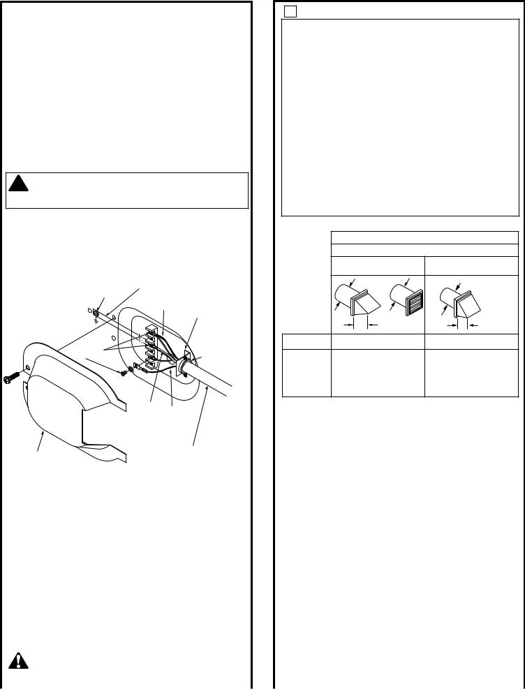
CONNECTING DRYER USING 4-WIRE CONNECTION (MUST BE USED FOR MOBILE HOME INSTALLATION)
NOTES: SInce January 1,1996, the National Electric code requires
that the new constructions utilize a 4-wire connection to an electric dryer
 WARNING:Only a 4-conductor cord shall be used when the appliance is installed in a location where grounding through the neutral conductor is prohibited. Grounding through the neutral is prohibited for the new branch-circuit installations, mobile homes, recreational vehicles, and areas where local codes prohibit grounding through the neutral conduction.
REMOVE GROUND STRAP AND DISCARD. KEEP GREEN GROUND SCREW
SCREWS
(3)
WIRE
L1 
 N
N  L2
L2 

RELOCATE GREEN
GROUND SCREW HERE
GREEN OR YELLOW WIRE
STRAIN
RELIEF BRACKET
|
NEUTRAL |
|
|
(White) |
|
|
|
3/4", UL |
|
HOT |
RECOGNIZED |
|
WIRE |
STRAIN RELIEF |
COVER |
4 #10 AWG MINIMUM COPPER |
|
CONDUCTORS OR 120/240V 30A POWER |
||
|
SUPPLY CORD KIT MARKED FOR USE |
|
|
WITH DRYERS & PROVIDED WITH |
|
2 |
CLOSED LOOP OR SPADE TERMINALS |
|
WITH UPTURNED ENDS (NOT SUPPLIED). |
||
Installation Instructions
1.Turn off the circuit breaker (s) (30 amp) or remove the dryer’s circuit fuse at the electrical box.
2.Be sure the dryer cord is unplugged from the wall receptacle.
3.Remove the power cord cover located at the lower back.
4.Remove and discard ground strap. Keep the green ground screw for step 7.
5.Install 3/4 in. UL recognized strain relief to power cord entry hole. Bring power cord through strain relief.
6.Connect power cord as follows:
A. Connect the 2 hot lines to the outer screws of
the terminal block (marked L1 and L2).
B. Connect the neutral (white) line to the center of the terminal block (marked N).
7.Attach ground wire of power cord with the green ground screw (hole above strain relief bracket). Tighten all terminal block screws (3) completely.
8.Properly secure power cord to strain relief.
9.Reinstall the cover.
 WARNING: NEVER LEAVE THE COVER OFF OF THE TERMINAL BLOCK.
CONNECTING DRYER USING 3-WIRE CONNECTION
IF REQUIRED, BY LOCAL CODE, |
|
|
INSTALL EXTERNAL GROUND |
|
|
(NOT PROVIDED) TO GROUNDED |
|
|
METAL, COLD WATER PIPE, OR |
GREEN |
|
OTHER ESTABLISHED GROUND |
||
GROUND |
||
DETERMINED BY A QUALIFIED |
SCREW |
|
ELECTRICIAN. |
||
|
||
SCREWS |
|
|
(3) |
|
GROUND
STRAP
HOT |
STRAIN RELIEF |
WIRE |
|
|
BRACKET |
L1 |
3/4", UL |
|
|
||
L2 |
RECOGNIZED |
|
STRAIN RELIEF |
||
|
3 EXHAUST INFORMATION
 WARNING - IN CANADA AND IN THE UNITED
STATES, THE REQUIRED EXHAUST DUCT DIAMETER
IS 4 IN (102mm). DO NOT USE DUCT LONGER THAN SPECIFIED IN THE EXHAUST LENGTH TABLE.
Using exhaust longer than specified length will:
•Increase the drying times and the energy cost.
•Reduce the dryer life.
•Accumulate lint, creating a potential fire hazard.
The correct exhaust installation is YOUR RESPONSIBILITY. Problems due to incorrect installation are not covered
by the warranty.
Remove and discard existing plastic or metal foil transition duct and replace with UL listed transition duct.
The MAXIMUM ALLOWABLE duct length and number of bends of the exhaust system depends upon the type of duct, number of turns, the type of exhaust hood (wall cap), and all conditions noted below. The maximum duct length for rigid metal duct is shown in the table below.
EXHAUST LENGTH
RECOMMENDED MAXIMUM LENGTH |
|||
|
Exhaust Hood Types |
||
Recommended |
Use only for short |
||
run installations |
|||
|
|
||
|
|
4" DIA. |
|
4" DIA. |
4" DIA. |
|
|
4" |
|
2-1/2" |
|
No. of 90º |
Rigid |
Rigid |
|
Elbows |
Metal |
Metal |
|
0 |
90 Feet |
60 Feet |
|
1 |
60 Feet |
45 Feet |
|
2 |
45 Feet |
35 Feet |
|
3 |
35 Feet |
25 Feet |
|
4 |
25 Feet |
15 Feet |
|
|
|
|
NEUTRAL |
HOT |
|
|
|
|
|
|
|
|
|||
|
|
|
(White) |
WIRE |
|
EXHAUST SYSTEM CHECK LIST |
|
|
|
|
|
|
|
|
HOOD OR WALL CAP |
|
|
|
|
|
|
|
• Terminate in a manner to prevent back drafts or entry of birds or |
|
|
|
3 #10 AWG MINIMUM COPPER |
|
other wildlife. |
||
|
COVER |
|
• Termination should present minimal resistance to the exhaust air flow |
||||
|
CONDUCTORS OR 120/240V 30A POWER |
|
|||||
|
|
|
SUPPLY CORD KIT MARKED FOR USE |
|
and should require little or no maintenance to prevent clogging. |
||
|
|
|
WITH DRYERS & PROVIDED WITH CLOSED |
|
• Never install a screen in or over the exhaust duct.This could cause lint build up. |
||
|
|
|
LOOP OR SPADE TERMINALS WITH |
|
• Wall caps must be installed at least 12 in. above ground level or any other |
||
|
|
|
UPTURNED ENDS (NOT SUPPLIED). |
|
obstruction with the opening pointed down. |
||
|
1. Turn off the circuit breaker(s) (30 amp) or remove the dryer’s |
|
SEPARATION OF TURNS |
||||
|
circuit fuse at the electrical box. |
|
|
|
|
||
|
|
|
|
|
For best performance, separate all turns by at least 4 ft. of straight duct, |
||
|
2. Be sure the dryer cord is unplugged from the wall. |
|
|||||
|
|
including distance between last turn and exhaust hood. |
|||||
|
3. Remove the power cord cover located at the lower back. |
|
|||||
|
|
TURNS OTHER THAN 90º |
|||||
|
4. Install 3/4 in. UL recognized strain relief to power cord |
|
|||||
|
entry hole. Bring power cord through strain relief. |
|
• One turn of 45º or less may be ignored. |
||||
|
5. Connect power cord as follows: |
|
|
|
|
• Two 45º turns should be treated as one 90º turn. |
|
|
A. Connect the 2 hot lines to the outer screws of the |
|
• Each turn over 45º should be treated as one 90º turn. |
||||
|
terminal block (marked L1 and L2). |
|
SEALING OF JOINTS |
||||
|
B. Connect the neutral (white) line to the center of |
|
|||||
|
|
• All joints should be tight to avoid leaks. The male end of each section of |
|||||
|
the terminal block (marked N). |
|
|
|
|||
|
|
|
|
duct must point away from the dryer. |
|||
|
6. Be sure ground strap is connected to neutral (center) |
|
|||||
|
|
• Do not assemble the ductwork with fasteners that extend into the duct. |
|||||
|
terminal of block and to green ground screw on cabinet |
|
|||||
|
|
They will serve as a collection point for lint. |
|||||
|
rear. Tighten all terminal block screws (3) completely. |
|
|||||
|
|
• Duct joints can be made air and moisture-tight by wrapping the |
|||||
|
7. Properly secure power cord to strain relief. |
|
|||||
|
|
overlapped joints with duct tape. |
|||||
|
8. Reinstall the cover. |
|
|
|
|
||
|
|
|
|
|
• Horizontal runs should slope down toward the outdoors ½ inch per foot |
||
|
|
|
|
|
|
|
|
|
WARNING: NEVER LEAVE THE |
|
|
INSULATION |
|||
|
|
|
Duct work that runs through an unheated area or is near air conditioning |
||||
|
COVER OFF OF THE TERMINAL BLOCK. |
|
|
||||
|
|
3 |
should be insulated to reduce condensation and lint build-up. |
||||
|
|
|
|
|
|
|
|
 Loading...