


 Loading...
Corometrics®170 Series
SERVICE MANUAL |
MANUAL P/N 2000947-004 REV. C |
||||
|
|
|
|
|
|
|
|
|
|
|
|
|
|
|
|
|
|
|
|
|
|
|
|
|
|
|
|
|
|
|
|
|
|
|
|

Corometrics® 170 Series
SERVICE MANUAL |
MANUAL P/N 2000947-004 REV. C |
|||
|
|
|
|
|
|
|
|
|
|
|
|
|
|
|
|
|
|
|
|

GUARANTEE
All equipment sold by GE Medical Systems Information Technologies, is fully guaranteed as to materials and workmanship for a period of 1 year. Information Technologies reserves the right to perform guarantee service operations in its own factory, at an authorized repair station, or in the customer’s installation.
Our obligation under this guarantee is limited to repairing, or, at our option, replacing any defective parts of our equipment, except fuses or batteries, without charge, if such defects occur in normal service.
Claims for damage in shipment should be filed promptly with the transportation company. All correspondence covering the instrument should specify the model and serial numbers.
GE Medical Systems Information Technologies
A GE Medical Systems Company
GE Medical Systems Information Technologies will make available on request such circuit diagrams, component diagrams, component parts lists, descriptions, calibration instructions, or other information which will assist the users or appropriately qualified technical personnel to repair those parts of the equipment which are classified by GE Medical Systems Information Technologies as repairable. Refer to the service manual for further information.
!CAUTION: In the United States of America, Federal Law restricts this device to sale by or on the order of a physician.
Corometrics and Marquette are registered trademarks of GE Medical Systems Information Technologies. GE is a registered trademark of General Electric Company. All other product and brand names are trademarks or registered trademarks of their respective companies. ©2002-2004 GE Medical Systems Information Technologies. All rights reserved. No part of this manual may be reproduced without the permission of GE Medical Systems Information Technologies.

1
2
3
4
Contents
Safety . . . . . . . . . . . . . . . . . . . . . . . . . . . . . . . . . . . . . . . . . 1-1
General Information . . . . . . . . . . . . . . . . . . . . . . . . . . . . . . . . . . . . . . . . . . . . . . . . . . 1-2
Definitions of Terminology . . . . . . . . . . . . . . . . . . . . . . . . . . . . . . . . . . . . . . . . . . . . 1-3
Monitor Contraindications, Warnings, and Precautions . . . . . . . . . . . . . . . . . . . . 1-4
Equipment Symbols . . . . . . . . . . . . . . . . . . . . . . . . . . . . . . . . . . . . . . . . . . . . . . . . . 1-9
Introduction . . . . . . . . . . . . . . . . . . . . . . . . . . . . . . . . . . . . 2-1
Indications for Use . . . . . . . . . . . . . . . . . . . . . . . . . . . . . . . . . . . . . . . . . . . . . . . . . . . 2-2 Monitoring Methods . . . . . . . . . . . . . . . . . . . . . . . . . . . . . . . . . . . . . . . . . . . . . . . . . . 2-3 Features . . . . . . . . . . . . . . . . . . . . . . . . . . . . . . . . . . . . . . . . . . . . . . . . . . . . . . . . . . . 2-4 About Your Monitor . . . . . . . . . . . . . . . . . . . . . . . . . . . . . . . . . . . . . . . . . . . . . . . . . . 2-5
Controls, Indicators, and Connectors . . . . . . . . . . . . . . . 3-1
Front Panel Controls . . . . . . . . . . . . . . . . . . . . . . . . . . . . . . . . . . . . . . . . . . . . . . . . . 3-2
Front Panel Displays and Indicators . . . . . . . . . . . . . . . . . . . . . . . . . . . . . . . . . . . . 3-6
Front Panel Connectors . . . . . . . . . . . . . . . . . . . . . . . . . . . . . . . . . . . . . . . . . . . . . . 3-8
Strip Chart Recorder . . . . . . . . . . . . . . . . . . . . . . . . . . . . . . . . . . . . . . . . . . . . . . . . 3-12
Rear Panel Connectors . . . . . . . . . . . . . . . . . . . . . . . . . . . . . . . . . . . . . . . . . . . . . . 3-14
Setup Procedures . . . . . . . . . . . . . . . . . . . . . . . . . . . . . . . 4-1
Loading Strip Chart Paper . . . . . . . . . . . . . . . . . . . . . . . . . . . . . . . . . . . . . . . . . . . . 4-2 Turning the Monitor On . . . . . . . . . . . . . . . . . . . . . . . . . . . . . . . . . . . . . . . . . . . . . . . 4-7
Revision C |
Corometrics 170 Series |
5 |
|
2000947-004 |
|

5
6
Monitor Self-Test Routines . . . . . . . . . . . . . . . . . . . . . . . . . . . . . . . . . . . . . . . . . . . . 4-8
Customizing the Monitor . . . . . . . . . . . . . . . . . . . . . . . . . . . . . . . . . . . . . . . . . . . . . 4-10
Quick Reference Card . . . . . . . . . . . . . . . . . . . . . . . . . . . . . . . . . . . . . . . . . . . . . . . 4-18
Flasher Software Utility Upgrade . . . . . . . . . . . . . . . . . . . . . . . . . . . . . . . . . . . . . . 4-20
Theory of Operation . . . . . . . . . . . . . . . . . . . . . . . . . . . . . 5-1
Functional Overview . . . . . . . . . . . . . . . . . . . . . . . . . . . . . . . . . . . . . . . . . . . . . . . . . 5-2 Main Board Theory of Operation . . . . . . . . . . . . . . . . . . . . . . . . . . . . . . . . . . . . . . 5-17 FECG/IUP Board Theory of Operation . . . . . . . . . . . . . . . . . . . . . . . . . . . . . . . . . . 5-36
Functional Checkout Procedure . . . . . . . . . . . . . . . . . . . 6-1
Equipment Required . . . . . . . . . . . . . . . . . . . . . . . . . . . . . . . . . . . . . . . . . . . . . . . . . 6-2
General . . . . . . . . . . . . . . . . . . . . . . . . . . . . . . . . . . . . . . . . . . . . . . . . . . . . . . . . . . . . 6-3
Monitor Self-Test . . . . . . . . . . . . . . . . . . . . . . . . . . . . . . . . . . . . . . . . . . . . . . . . . . . . 6-4
Front Panel Pushbutton Test . . . . . . . . . . . . . . . . . . . . . . . . . . . . . . . . . . . . . . . . . . 6-5
Connecting the Simulator . . . . . . . . . . . . . . . . . . . . . . . . . . . . . . . . . . . . . . . . . . . . . 6-6
FECG Test . . . . . . . . . . . . . . . . . . . . . . . . . . . . . . . . . . . . . . . . . . . . . . . . . . . . . . . . . 6-7
Legplate Inspection . . . . . . . . . . . . . . . . . . . . . . . . . . . . . . . . . . . . . . . . . . . . . . . . . 6-12
Ultrasound Test . . . . . . . . . . . . . . . . . . . . . . . . . . . . . . . . . . . . . . . . . . . . . . . . . . . . 6-13
Fetal Movement Detection Test . . . . . . . . . . . . . . . . . . . . . . . . . . . . . . . . . . . . . . . 6-16
Ultrasound Transducer Test . . . . . . . . . . . . . . . . . . . . . . . . . . . . . . . . . . . . . . . . . . 6-18
Uterine Activity Test . . . . . . . . . . . . . . . . . . . . . . . . . . . . . . . . . . . . . . . . . . . . . . . . 6-19
Tocotransducer Test . . . . . . . . . . . . . . . . . . . . . . . . . . . . . . . . . . . . . . . . . . . . . . . . 6-21
Strain Gauge Transducer Test . . . . . . . . . . . . . . . . . . . . . . . . . . . . . . . . . . . . . . . . 6-22
Pattern Memory Test . . . . . . . . . . . . . . . . . . . . . . . . . . . . . . . . . . . . . . . . . . . . . . . . 6-23
Dual Heart Rate Test (Non-Pattern) . . . . . . . . . . . . . . . . . . . . . . . . . . . . . . . . . . . . 6-24
6 |
Corometrics 170 Series |
Revision C |
|
2000947-004 |
|

7
8
9
Alarm Test . . . . . . . . . . . . . . . . . . . . . . . . . . . . . . . . . . . . . . . . . . . . . . . . . . . . . . . . |
6-28 |
Serviceable Assemblies . . . . . . . . . . . . . . . . . . . . . . . . . . 7-1
General Anti-Static Handling Precautions . . . . . . . . . . . . . . . . . . . . . . . . . . . . . . . . 7-2 Transducer Plug Replacement Kits . . . . . . . . . . . . . . . . . . . . . . . . . . . . . . . . . . . . . 7-3 Nautilus Transducer Cable Replacement . . . . . . . . . . . . . . . . . . . . . . . . . . . . . . . 7-15 Removing the Monitor Top Cover . . . . . . . . . . . . . . . . . . . . . . . . . . . . . . . . . . . . . 7-19 Tocotransducer Calibration . . . . . . . . . . . . . . . . . . . . . . . . . . . . . . . . . . . . . . . . . . 7-20 Nautilus Ultrasound Transducer Top Cover Replacement . . . . . . . . . . . . . . . . . 7-30 Nautilus Transducer Reassembly . . . . . . . . . . . . . . . . . . . . . . . . . . . . . . . . . . . . . 7-32 Testing a Repaired Transducer (TOCO or US) . . . . . . . . . . . . . . . . . . . . . . . . . . . 7-34 Replacing the Main Board . . . . . . . . . . . . . . . . . . . . . . . . . . . . . . . . . . . . . . . . . . . . 7-35 Replacing the FECG/IUP Board . . . . . . . . . . . . . . . . . . . . . . . . . . . . . . . . . . . . . . . 7-36 Replacing the Membrane Switch Panel . . . . . . . . . . . . . . . . . . . . . . . . . . . . . . . . . 7-37 Replacing a Front Panel Connector . . . . . . . . . . . . . . . . . . . . . . . . . . . . . . . . . . . . 7-40 Servicing the Recorder . . . . . . . . . . . . . . . . . . . . . . . . . . . . . . . . . . . . . . . . . . . . . . 7-41 Boot ROM Error Codes . . . . . . . . . . . . . . . . . . . . . . . . . . . . . . . . . . . . . . . . . . . . . . 7-49
Peripheral Devices . . . . . . . . . . . . . . . . . . . . . . . . . . . . . . |
8-1 |
Remote Marks Connectors . . . . . . . . . . . . . . . . . . . . . . . . . . . . . . . . . . . . . . . . . . . . 8-2
Telemetry Connector . . . . . . . . . . . . . . . . . . . . . . . . . . . . . . . . . . . . . . . . . . . . . . . . 8-3
RS-232 Connectors . . . . . . . . . . . . . . . . . . . . . . . . . . . . . . . . . . . . . . . . . . . . . . . . . . 8-4
Maintenance . . . . . . . . . . . . . . . . . . . . . . . . . . . . . . . . . . . |
9-1 |
Cleaning . . . . . . . . . . . . . . . . . . . . . . . . . . . . . . . . . . . . . . . . . . . . . . . . . . . . . . . . . . . 9-2
Preventative Maintenance Inspection . . . . . . . . . . . . . . . . . . . . . . . . . . . . . . . . . . . 9-5
Revision C |
Corometrics 170 Series |
7 |
|
2000947-004 |
|

10
11
Specifications . . . . . . . . . . . . . . . . . . . . . . . . . . . . . . . . . |
10-1 |
General Monitor . . . . . . . . . . . . . . . . . . . . . . . . . . . . . . . . . . . . . . . . . . . . . . . . . . . . 10-2
Operating Modes . . . . . . . . . . . . . . . . . . . . . . . . . . . . . . . . . . . . . . . . . . . . . . . . . . . 10-3
Strip Chart Recorder . . . . . . . . . . . . . . . . . . . . . . . . . . . . . . . . . . . . . . . . . . . . . . . . 10-4
Parts Lists . . . . . . . . . . . . . . . . . . . . . . . . . . . . . . . . . . . . 11-1
2000268-188, Model 171 Final Assembly . . . . . . . . . . . . . . . . . . . . . . . . . . . . . . . . 11-2 2000268-189, Model 172 Final Assembly . . . . . . . . . . . . . . . . . . . . . . . . . . . . . . . . 11-5 2001972-037, Model 173 Final Assembly . . . . . . . . . . . . . . . . . . . . . . . . . . . . . . . . 11-8 2001972-038, Model 174 Final Assembly . . . . . . . . . . . . . . . . . . . . . . . . . . . . . . . . 11-11 2264AAX, Button-Style Nautilus Tocotranducer Assembly Parts List . . . . . . . 11-14 5700GAX, Button-Style Nautilus Ultrasound Transducer Assembly Parts List 11-15 5700KAX, Loop-Style Nautilus Ultrasound Transducer Assembly Parts List . 11-16 2264DAX, Loop-Style Nautilus Tocotransducer Assembly Parts List (5-ft cord) 11-17 1509AAO/BAO, Qwik Connect Plus Legplate Assembly Parts List . . . . . . . . . 11-18 Block Diagrams. . . . . . . . . . . . . . . . . . . . . . . . . . . . . . . . . . . . . . . . . . . . . . . . . . . . . 11-19
8 |
Corometrics 170 Series |
Revision C |
|
2000947-004 |
|

Chapter 1
! Safety
The information presented in this section is important for the safety of both the patient and operator and also serves to enhance equipment reliability. This chapter describes how the terms Danger, Warning, Caution, Important, and Note are used throughout the manual. In addition, standard equipment symbols are defined.
This section includes the following important information:
General Information . . . . . . . . . . . . . . . . . . . . . . . . . . . . . . . . . . . . . . 1-2
Definitions of Terminology . . . . . . . . . . . . . . . . . . . . . . . . . . . . . . . . 1-3
Monitor Contraindications, Warnings, and Precautions . . . . . . . . . . 1-4
Equipment Symbols . . . . . . . . . . . . . . . . . . . . . . . . . . . . . . . . . . . . . . 1-9
Revision C |
170 Series Monitor |
1-1 |
|
2000947-004 |
|

Safety: General Information
General Information
General Use
If the monitor is cold to the touch or below ambient temperature, allow it to stabilize before use.
To ensure patient safety, use only parts and accessories manufactured or recommended by GE Medical Systems Information Technologies. Parts and accessories used shall meet the requirements of EN60601.1.1.
Disposable devices are intended for single use only. They should not be reused.
Periodically, and whenever the integrity of the monitor is in doubt, test all functions.
Refer to the “Maternal/Fetal Monitoring Operator’s Manual” for information concerning the limitations of internal and external fetal heart rate monitoring techniques.
Responsibility of the Manufacturer
GE is responsible for the effects on safety, reliability, and performance if:
assembly operations, extensions, readjustments, modifications, or repairs are carried out by persons authorized by GE;
the electrical installation of the relevant room complies with the requirements of appropriate regulations; and
the monitor is used in accordance with the instructions of use.
Responsibility of the User
This device is intended for use by clinical professionals who are expected to know the medical procedures, practices, and terminology required to monitor obstetrical patients. This manual documents all possible parameters available in the 170 Series of monitors. It is the responsibility of each hospital to ensure that the Labor and Delivery staff is trained in all aspects of the selected model.
The 170 Series Monitor is designed to assist the perinatal staff by providing information regarding the clinical status of the fetus during labor. The monitor does not replace observation and evaluation of the mother and fetus at regular intervals, by a qualified care provider, who will make diagnoses and decide on treatments or interventions. Visual assessment of the monitor display and strip chart must be combined with knowledge of patient history and risk factors to properly care for the mother and fetus.
1-2 |
170 Series Monitor |
Revision C |
|
2000947-004 |
|
Safety: Definitions of Terminology
Definitions of Terminology
Six types of special notices are used throughout this manual. They are: Danger, Warning, Caution, Contraindication, Important, and Note. The warnings and cautions in this Safety section relate to the equipment in general and apply to all aspects of the monitor. Be sure to read the other chapters because there are additional warnings and cautions which relate to specific features of the monitor.
When grouped, warnings and cautions are listed alphabetically and do not imply any order of importance.
|
Table 1-1. Definitions of Terminology |
||
|
|
|
|
Danger |
|
A DANGER notice indicates an imminently |
|
|
hazardous situation which, if not avoided, will result |
||
|
|
in death or serious injury. |
|
|
|
|
|
Warning |
|
A WARNING indicates a potentially hazardous |
|
|
situation which, if not avoided, could result in death |
||
|
|
or serious injury. |
|
|
|
|
|
|
|
A CAUTION indicates a potentially hazardous |
|
Caution |
|
situation which, if not avoided, may result in minor |
|
|
or moderate injury. Cautions are also used to |
||
|
|
||
|
|
avoid damage to equipment. |
|
|
|
|
|
|
|
A CONTRAINDICATION describes any special |
|
Contraindication |
symptom or circumstance that renders the use of a |
||
remedy or the carrying out of a procedure |
|||
|
|
||
|
|
inadvisable, usually because of a risk. |
|
|
|
|
|
Important |
|
An IMPORTANT notice indicates an emphasized |
|
|
note. It is something you should be particularly |
||
|
|
aware of; something not readily apparent. |
|
|
|
|
|
Note |
|
A NOTE indicates a particular point of information; |
|
|
something on which to focus your attention. |
||
|
|
||
|
|
|
|
Revision C |
170 Series Monitor |
1-3 |
|
2000947-004 |
|

Safety: Monitor Contraindications, Warnings, and Precautions
Monitor Contraindications, Warnings, and
Precautions
Warnings
WARNINGS
ACCIDENTAL SPILLS—In the event that fluids are accidentally spilled on the monitor, take the monitor out of operation and inspect for damage.
APPLICATION—This monitor is not designed for direct cardiac connection.
CONDUCTIVE CONNECTIONS—Avoid making any conductive connections to applied parts (patient connection) which are likely to degrade safety.
CONDUCTIVE PARTS—Ensure that the conductive parts of the lead electrodes and associated connectors do not contact other conductive parts including earth.
DEFIBRILLATION—During defibrillation, all personnel must avoid contact with the patient and monitor to avoid a dangerous shock hazard. In addition, proper placement of the paddles in relation to the electrodes is required to minimize harm to the patient.
ELECTRICAL SHOCK—To reduce the risk of electrical shock, do not remove monitor cover. Refer servicing to qualified personnel.
ELECTROMAGNETIC INTERFERENCE—Be aware that strong electromagnetic fields may interfere with monitor operation. Interference prevents the clear reception of signals by the monitor. If the hospital is close to a strong transmitter such as TV, AM or FM radio, police or fire stations, a HAM radio operator, an airport, or cellular phone, their signals could be picked up as signals by the monitor. If you feel interference is affecting the monitor, contact your Service Representative to check the monitor in your environment. Refer to page 1-8 for additional information.
1-4 |
170 Series Monitor |
Revision C |
|
2000947-004 |
|

Safety: Monitor Contraindications, Warnings, and Precautions
WARNINGS
ELECTROSURGERY—The monitor is not designed for use with high-frequency surgical devices. In addition, measurements may be affected in the presence of strong electromagnetic sources such as electrosurgery equipment.
EXPLOSION HAZARD—Do not use this equipment in the presence of flammable anesthetics or inside an oxygen tent.
GROUNDING—Do not defeat the three-wire grounding feature of the power cord by means of adaptors, plug modifications, or other methods. A dangerous shock hazard to both patient and operator may result.
INSTRUCTIONS—For continued and safe use of this equipment, it is necessary to follow all listed instructions. However, the instructions provided in this manual in no way supersede established medical procedures concerning patient care. The monitor does not replace observation and evaluation of the patient, at regular intervals, by a qualified care provider who will make diagnoses and decide on treatments and interventions.
INTERFACING OTHER EQUIPMENT—Monitoring equipment must be interfaced with other types of medical equipment by qualified biomedical engineering personnel. Be certain to consult manufacturers’ specifications to maintain safe operation.
LEAKAGE CURRENT TEST—The interconnection of auxiliary equipment with this device may increase the total leakage current. When interfacing with other equipment, a test for leakage current must be performed by qualified biomedical engineering personnel before using with patients. Serious injury or death could result if the leakage current exceeds applicable standards. The use of accessory equipment not complying with the equivalent safety requirements of this equipment may lead to a reduced level of safety of the resulting system. Consideration relating to the choice shall include: use of the accessory in the patient vicinity; and evidence that the safety certification of the accessory has been performed in accordance with the appropriate EN60601.1 and/or EN60601.1.1 harmonized national standard.
Revision C |
170 Series Monitor |
1-5 |
|
2000947-004 |
|

Safety: Monitor Contraindications, Warnings, and Precautions
WARNINGS
LINE ISOLATION MONITOR TRANSIENTS—Line isolation monitor transients may resemble actual cardiac waveforms, and thus cause incorrect heart rate determinations and alarm activation (or inhibition).
STRANGULATION—Make sure all patient cables, leadwires, and tubing are positioned away from the patient’s head to minimize the risk of accidental strangulation.
WATER BIRTHS—Do not use the monitor to directly monitor patients during water births, in whirlpool or submersion water baths, during showers, or in any other situation where the mother is immersed in water. Doing so may result in electrical shock hazard.
1-6 |
170 Series Monitor |
Revision C |
|
2000947-004 |
|

Safety: Monitor Contraindications, Warnings, and Precautions
Cautions
CAUTIONS
ANNUAL SERVICING—For continued safety and performance of the monitor, it is recommended that the calibration, accuracy, and electrical safety of the monitor be verified on an annual basis by an GE Service Representative.
DAILY TESTING—It is essential that the monitor and accessories be inspected every day. It is recommended practice to initiate the monitor’s self-test feature at the beginning of each monitoring session; follow the instructions in “Chapter 4, Setup Procedures”.
ENVIRONMENT—The performance of the monitor has not been tested in certain areas, such as x-ray and imaging suites. The monitor is not recommended for use in these environments.
PERFORMANCE—Report all problems experienced with the monitor. If the monitor is not working properly, contact your Service Representative for service. The monitor should not be used if it is not working properly.
PINCHING—Keep fingers clear of the paper roller because the roller could pinch your fingers.
TRAPPING—Keep hands, hair, jewelry, and loose clothing away from the paper roller because the roller could trap these items.
TRIPPING—Arrange monitoring equipment so that cords and cables do not present a tripping hazard.
Revision C |
170 Series Monitor |
1-7 |
|
2000947-004 |
|

Safety: Monitor Contraindications, Warnings, and Precautions
Electromagnetic Interference
This device has been tested and found to comply with the limits for medical devices to the IEC 601-1-2:1993, EN60601-1-2:1994, Medical Device Directive 93/42/EEC. These limits are designed to provide reasonable protection against harmful interference in a typical medical installation.
However, because of the proliferation of radio-frequency transmitting equipment and other sources of electrical noise in the health-care and home environments (for example, cellular phones, mobile two-way radios, electrical appliances), it is possible that high levels of such interference due to close proximity or strength of a source, may result in disruption of performance of this device.
This equipment generates, uses, and can radiate radio frequency energy and, if not installed and used in accordance with these instructions, may cause harmful interference with other devices in the vicinity. Disruption or interference may be evidenced by erratic readings, cessation of operation, or incorrect functioning. If this occurs, the site of use should be surveyed to determine the source of this disruption, and actions taken to eliminate the source.
The user is encouraged to try to correct the interference by one or more of the following measures:
Turn equipment in the vicinity off and on to isolate the offending equipment.
Reorient or relocate the other receiving device.
Increase the separation between the interfering equipment and this equipment.
If assistance is required, contact your GE Service Representative.
1-8 |
170 Series Monitor |
Revision C |
|
2000947-004 |
|
Safety: Equipment Symbols
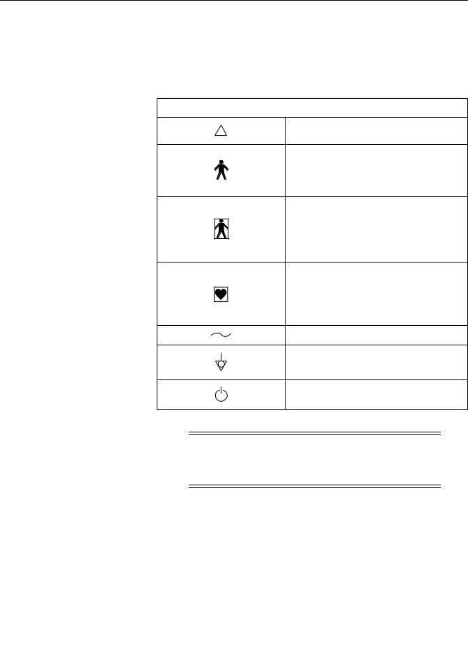
Equipment Symbols
The following is a list of symbols used on products manufactured by GE. Some symbols may not appear on your unit.
Table 1-2. Equipment Symbols
! |
ATTENTION: Consult accompanying documents. |
TYPE B EQUIPMENT. Type B equipment is suitable for intentional external and internal application to the patient, excluding direct cardiac application.
TYPE BF EQUIPMENT. Type BF equipment is suitable for intentional external and internal application to the patient, excluding direct cardiac application. Type BF equipment has an F-type applied part.
TYPE CF EQUIPMENT. Type CF equipment is suitable for intentional external and internal application to the patient, including direct cardiac application. Type CF equipment has an F-type applied part.
ALTERNATING CURRENT (AC).
EQUIPOTENTIALITY.
ON/STANDBY: button toggles between full power and standby.
CAUTION
AC MAINS—The On/Standby switch does not disconnect the monitor from AC mains power. To completely remove power, you must disconnect the power cord from the AC wall outlet.
Revision C |
170 Series Monitor |
1-9 |
|
2000947-004 |
|

Safety: Equipment Symbols
For your notes
1-10 |
170 Series Monitor |
Revision C |
|
2000947-004 |
|

Chapter 2
Introduction
This section lists the indications for use for monitors in the 170 Series as well as provides an explanation of the different patient monitoring modalities.
This section summarizes the clinical applications of monitors in the 170 Series:
Indications for Use . . . . . . . . . . . . . . . . . . . . . . . . . . . . . . . . . . . . . . . 2-2 Monitoring Methods. . . . . . . . . . . . . . . . . . . . . . . . . . . . . . . . . . . . . . 2-3 Features . . . . . . . . . . . . . . . . . . . . . . . . . . . . . . . . . . . . . . . . . . . . . . . 2-4 About Your Monitor. . . . . . . . . . . . . . . . . . . . . . . . . . . . . . . . . . . . . . 2-5
Revision C |
170 Series Monitor |
2-1 |
|
2000947-004 |
|

Introduction: Indications for Use
Indications for Use
Models 171 and 172
Models 171 and 172 Fetal Monitors are indicated for use in the monitoring of the fetus during the antepartum period as well as throughout labor and delivery. Each monitor also has an optional monitoring mode to detect fetal body movements.
Models 173 and 174
Models 173 and 174 Fetal Monitors are indicated for use in the monitoring of the fetus throughout labor and delivery. Each monitor also has an optional monitoring mode to detect fetal body movements.
2-2 |
170 Series Monitor |
Revision C |
|
2000947-004 |
|
Introduction: Monitoring Methods
Monitoring Methods
The following is a summary of all the clinical monitoring methods found in the 170
Series.
Fetal Heart Rate
External Method, Pulsed Doppler Ultrasound
Ultrasound monitoring is available on all 170 Series Monitors. Models 171 and 173 provide a single ultrasound channel, while Models 172 and 174 provide two ultrasound channels.
Fetal heart rate can be measured externally using pulsed Doppler Ultrasound. A transducer placed on the mother’s abdomen is used to direct an ultrasonic beam toward the fetal heart and to sense Doppler shifted echoes created by moving cardiac structures. A patented autocorrelation process is used to determine the timing of successive cardiac cycles. The resulting fetal heart rate (FHR) pattern is recorded on the strip chart paper and the FHR appears on the digital display.
Internal Method, Direct Fetal Electrocardiogram (FECG)
FECG is available on Models 173 and 174 only. The Model 173 provides a dedicated FECG connector. The Model 174 provides a combi-connector which can be used for either FECG or US.
FECG signals are obtained via a spiral electrode attached to the fetal presenting part. FHR is computed on a beat-to-beat basis using the R-to-R time interval of the QRS complexes. The instantaneous FHR pattern is printed on the strip chart paper and the FHR appears on the digital display.
Maternal Uterine Activity
External Method, Tocotransducer (TOCO)
Maternal uterine activity is measured externally using a tocotransducer (toco). Relative pressure within the uterus is measured using a tocotransducer attached to the mother’s abdomen in the area of the uterine fundus. The readings are plotted on the strip chart paper in a relative scale from 0 to 100 as well as shown on the digital display. All 170 Series Monitors provide external uterine activity monitoring.
Internal Method, Intrauterine Pressure Catheter and Strain Gauge (IUP)
IUP is available on Models 173 and 174 only.
Intrauterine pressure is measured using a transcervical catheter. The pressure trend is plotted over the range of 0 to 100 mmHg and the readings appear on the digital display.
Revision C |
170 Series Monitor |
2-3 |
|
2000947-004 |
|

Introduction: Features
Features
The 170 Series is a family of fetal monitors offering various combinations of modalities to suit your institution’s needs. Each monitor boasts the following qualities:
The strip chart recorder is a quiet, easy-to-load, high resolution thermal array printer. The recorder prints continuous trends and alphanumeric data on one strip chart.
Automatic mode selection is provided simply by inserting the appropriate transducer plug into the front panel receptacle.
Wide beam ultrasound transducer provides an advanced level of system performance.
Transducer connectors are easy-to-use, color-coded, and durable.
Frequently-used functions are controlled by front panel buttons—including audio volume, uterine activity reference, alarm silence, event mark, paper advance, and user setup controls.
The ultrasound mode provides clean accurate traces with few “dropouts” because of a patented autocorrelation processing.
Fetal heart rate alarm limits are user-defined, with pre-set defaults.
Alarm silencing is controlled by a front panel pushbutton—colored for easy recognition.
Fetal heart rate alarm conditions have both audible and visual indications. The audible indicator can be silenced on an alarm-by-alarm basis.
Two RS-232C ports provide interfacing to external devices.
2-4 |
170 Series Monitor |
Revision C |
|
2000947-004 |
|

Introduction: About Your Monitor
About Your Monitor
This manual describes all monitors in the 170 Series; therefore some sections may not apply to your model monitor. Refer to Table 2-1.
Model 171
The Model 171 Antepartum Fetal Monitor provides singleton ultrasound and external uterine activity monitoring.
Model 172
The Model 172 Antepartum Fetal Monitor provides dual ultrasound and external uterine activity monitoring.
Model 173
The Model 173 Intrapartum Monitor provides dual heart rate monitoring using FECG and ultrasound. The monitor also provides external uterine activity monitoring using a tocotransducer or internal monitoring using an intrauterine pressure catheter (IUPC).
Model 174
The Model 174 Intrapartum Monitor provides dual heart rate monitoring using FECG/ultrasound or dual ultrasound. The monitor also provides external uterine activity monitoring using a tocotransducer or internal monitoring using an IUPC.
Table 2-1. Summary of Features
Feature |
171 |
172 |
173 |
174 |
|
|
|
|
|
External uterine activity (TOCO) |
9 |
9 |
9 |
9 |
|
|
|
|
|
Internal uterine activity (IUPC) |
|
|
9 |
9 |
|
|
|
|
|
Ultrasounda |
9 |
9 |
9 |
9 |
Dual ultrasound |
|
9 |
|
9 |
|
|
|
|
|
FECGa |
|
|
9 |
9 |
Fetal heart rate alarms |
9 |
9 |
9 |
9 |
|
|
|
|
|
Fetal movement detection (optional) |
9 |
9 |
9 |
9 |
|
|
|
|
|
Heartbeat coincidence |
|
9 |
9 |
9 |
|
|
|
|
|
Fetal heart rate offset |
|
9 |
9 |
9 |
|
|
|
|
|
a The Model 174 has a combi-connector for the primary FHR that can be used for either US or FECG.
Revision C |
170 Series Monitor |
2-5 |
|
2000947-004 |
|

For your notes
2-6 |
170 Series Monitor |
Revision C |
|
2000947-004 |
|

Chapter 3
Controls, Indicators, and
Connectors
This section describes all possible controls, indicators, and connectors in the 170 Series.
This section contains the following information:
Front Panel Controls. . . . . . . . . . . . . . . . . . . . . . . . . . . . . . . . . . . . . . 3-2
Front Panel Displays and Indicators. . . . . . . . . . . . . . . . . . . . . . . . . . 3-6
Front Panel Connectors . . . . . . . . . . . . . . . . . . . . . . . . . . . . . . . . . . . 3-8
Strip Chart Recorder. . . . . . . . . . . . . . . . . . . . . . . . . . . . . . . . . . . . . 3-12
Rear Panel Connectors . . . . . . . . . . . . . . . . . . . . . . . . . . . . . . . . . . . 3-14
Revision C |
170 Series Monitor |
3-1 |
|
2000947-004 |
|
Controls, Indicators, and Connectors: Front Panel Controls
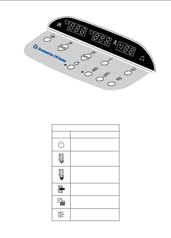
Front Panel Controls
Figure 3-1. Front Panel Controls (Model 172 shown)
Table 3-1. Front Panel Controls
Symbol |
Name |
|
Power |
|
Record |
|
Paper Advance |
|
Mark/Offset |
|
Setup |
|
Volume |
3-2 |
170 Series Monitor |
Revision C |
|
2000947-004 |
|

Controls, Indicators, and Connectors: Front Panel Controls
Table 3-1. Front Panel Controls
UA Reference
Alarm Silence
 Power Button and Indicator
Pressing the blue Power button turns the monitor on and illuminates the green indicator to the left of the button. Pressing the button again puts the monitor in standby and extinguishes the indicator.
 Record Button and Indicator
Pressing the Record pushbutton activates the recorder, provided paper is installed; the amber indicator illuminates to the left of the button. Pressing the button again turns the recorder off and extinguishes the indicator.
 Paper Advance Button
Pressing the Paper Advance button causes the recorder to advance chart paper at a rate of 40 cm/min for as long as the button is pressed. If the recorder is on, twenty seconds after the button is released, the recorder prints the time, date, active trends legends, and chart speed.
Mark/Offset Button
The Mark/Offset button is a multifunction button:
Mark
Briefly pressing the button prints an event mark  on the bottom two lines of the heart rate grid.
Offset (Models 172, 173, and 174 Only)
When the heart rate offset mode is enabled, pressing and holding the Mark/Offset button for at least two seconds shifts the secondary FHR trend +20 BPM for visibility purposes. You will hear a “beep” for confirmation. Refer to the “170 Series Operator’s Manual” for more information.
Revision C |
170 Series Monitor |
3-3 |
|
2000947-004 |
|

Controls, Indicators, and Connectors: Front Panel Controls
 Setup Button
Pressing and holding this button while the monitor is on enters a user setup mode for configuring the monitor.
Pressing and holding this button during power up enters a service setup mode.
Refer to “Chapter 4, Setup Procedures” for instructions.
 Volume Buttons
The Volume buttons are used to raise ( ) and lower (
  ) the volume of the audio signals emitted by the speaker. The volume buttons are also used during setup.
Model 171
This monitor has two volume buttons used to control the ultrasound audio.
Models 172, 173, and 174
These monitors have four volume buttons. The left pair controls the audio signals for the mode shown in the primary FHR display; likewise, the right pair of buttons controls the audio for the mode shown in the secondary FHR display.
Setup Mode
When the monitor is in setup mode (user or service), the volume buttons change: the setting or value shown in the FHR display; or the monitor feature code shown in the UA display. (For Models 172, 173, and 174, only the leftmost volume controls are active during setup mode.)
3-4 |
170 Series Monitor |
Revision C |
|
2000947-004 |
|

Controls, Indicators, and Connectors: Front Panel Controls
 UA Reference Button
The UA Reference button is used to set the uterine activity pressure reference. This button is also used during setup.
Setting a Baseline for External Monitoring (Tocotransducer)
Briefly pressing the UA Reference button sets the pressure baseline at a preset default. The monitor is shipped from the factory with a default setting of 10 relative units. Qualified service personnel can access a service screen to set the default to 5, 10, 15, 20, or 25 relative units.
Pressing this button for more than two seconds causes the uterine activity reference value to override the default setting and cycle through all available selections: 5, 10, 15, 20, or 25 relative units, starting at the default setting—until the button is released. While the button is held down, the strip chart tracing remains unchanged. Once the button is released, the recorder trace takes on this new value. This value is stored as the new baseline for the currently measured uterine activity signal.
Setting a Baseline for Internal Monitoring (IUPC)
Pressing the UA Reference button sets the pressure baseline at 0 mmHg.
NOTE: IUPC monitoring is only available on Models 173 and 174.
Setup Mode
When the monitor is in setup mode, the UA Reference button selects the active display. Pressing the button alternates between the UA display (which shows a monitor feature code) and the FHR display (which shows the setting or value for the selected feature code). When the UA display is active, the ± sign lights. When the FHR display is active, the heartbeat indicator  lights.
 Alarm Silence Button
This button is yellow for easy recognition. Pressing the Alarm Silence button removes the audible indication of an individual fetal heart rate alarm.
NOTE: Silencing an alarm does not affect the visual indications.
Revision C |
170 Series Monitor |
3-5 |
|
2000947-004 |
|

Controls, Indicators, and Connectors: Front Panel Displays and Indicators
Front Panel Displays and Indicators
Fetal Heart Rate Display(s) and Indicator(s)
FHR Display
A three-digit yellow numeric display indicates the fetal heart rate in beats per minute. The value flashes during an alarm condition.
Heartbeat Indicator
A yellow heart shaped indicator flashes with each detected valid heartbeat for the fetal heart.
Primary Versus Secondary (Models 172, 173, and 174 only)
Refer to Table 3-2 for a summary of display positions relative to connectors.
Uterine Activity Display
This green three-digit display indicates the uterine activity values.
Tocotransducer
If uterine activity is measured using a tocotransducer, the uterine activity value displays in relative units. A plus sign flashes when the uterine activity value exceeds the strip chart range of 100 relative units.
IUP (Models 173 and 174 Only)
If uterine activity is measured using an intrauterine pressure catheter or a strain gauge pressure transducer, the uterine activity value displays in mmHg.
.
Table 3-2. Display/Connector Summary
Monitor |
Model 171 |
Model 172 |
|
Model 173 |
|
|
Model 174 |
|
|
Mode |
|
|
|
|
|
TOCO |
US1 |
|
TOCO |
US |
TOCO US1 |
US2 TOCO |
US |
FECG |
or |
or |
US2 |
or |
|
|
|
|
|
|
|
IUP |
FECG |
|
IUP |
Display |
|
1 |
2 |
|
|
|
|
|
|
|
|
|
|
|
|
|
|
||
Connector |
|
1 |
2 |
|
|
|
|
|
|
3-6 |
170 Series Monitor |
Revision C |
|
2000947-004 |
|
Loading...