


Dryers
GEAppliances.com
Safety Instructions........................ |
2–4 |
Operating Instructions |
|
Controls ........................................................... |
5–7 |
Cycle Options............................................... |
8, 9 |
Using the Dryer.............................................. |
10 |
Installation Instructions |
|
Before You Begin.................................. |
11, 12 |
Connecting an |
|
Electric Dryer.......................................... |
14–16 |
Exhausting the Dryer ........................ |
17–23 |
Final Setup........................................................ |
24 |
Location of your Dryer...................... |
12, 13 |
Reversing the Door Swing ............. |
25–27 |
Stacking the Washer |
|
and Dryer.................................................. |
28–30 |
Owner’s Manual &
Installation Instructions
DCVH480EK
DCVH485EK
PCVH480EK
PCVH485EK
Sécheuses
Manuel d’utilisation et d’installation
La section française commence à la page 37
Troubleshooting Tips |
.............32–34 |
|
Secadoras |
|
Consumer Support |
|
|
|
|
|
Manual del propietario |
|||
Consumer Support................ |
Back Cover |
|
|
|
Warranty (Canada).................................... |
36 |
|
e instalación |
|
..............................................Warranty (U.S.) |
35 |
La sección en español empieza en la página 73 |
||
SAVE THESE INSTRUCTIONS
Write the model and serial numbers here:
Model # ______________
Serial # _______________
They are on the label on the front of the dryer behind the door.
175D1807P634 49-90370-1 05-14 GE
Safety Instructions
Operating Instructions
Troubleshooting Tips
Consumer Support
IMPORTANT SAFETY INFORMATION.
READ ALL INSTRUCTIONS BEFORE USING.
 WARNING!
For your safety, the information in this manual must be followed to minimize the risk of fire or explosion, electric shock, or to prevent property damage, personal injury, or death.
|
|
Do not store or use gasoline or other |
Installation and service must be |
flammable vapors and liquids in the |
performed by a qualified installer |
vicinity of this or any other appliance. |
or service agency. |
|
|
PROPER INSTALLATION
This dryer must be properly installed and located in accordance with the Installation Instructions before it is used. Installation Instructions are included in the back of this manual.
Properly ground dryer to conform with all governing codes and ordinances. Follow details in Installation Instructions.
Install or store where it will not be exposed to temperatures below freezing or exposed to water or weather, which could cause permanent damage and invalidate the warranty.
Connect to a properly rated, protected and sized power supply circuit to avoid electrical overload.
Remove all sharp packing items and dispose of all shipping materials properly.
Exhaust/Ducting
1 Dryers MUST be exhausted to the outside to prevent large amounts of moisture and lint from being blown into the room.
2 Use only rigid metal 4” diameter ductwork inside the dryer cabinet. Use only rigid metal or flexible metal 4-in diameter ductwork for exhausting to the outdoors. Never use plastic or other combustible, easy-to-puncture ductwork.
For complete details, follow the Installation Instructions.
2
GEAppliances.com
 WARNING!
YOUR LAUNDRY AREA
Keep the area underneath and around your appliances free of combustible materials, (lint, paper, rags, etc.), gasoline, chemicals and other flammable vapors and liquids.
Keep the floor around your appliances clean and dry to reduce the possibility of slipping.
Close supervision is necessary if this appliance is used by or near children. Do not allow children to play on, with or inside this or any other appliance.
Keep the area around the exhaust opening and adjacent surrounding areas free from the accumulation of lint, dust and dirt.
Keep all laundry aids (such as detergents, bleaches, etc.) out of the reach of children, preferably in a locked cabinet. Observe all warnings on container labels to avoid injury.
Never climb on or stand on the dryer top.
WHEN USING YOUR DRYER
Never reach into the dryer while the drum is moving. Before loading, unloading or adding clothes, wait until the drum has completely stopped.
Clean the lint filter before each load to prevent lint accumulation inside the dryer or in the room. DO
NOT OPERATE THE DRYER WITHOUT THE LINT FILTER IN PLACE.
Do not wash or dry articles that have been cleaned in, washed in, soaked in or spotted
with combustible or explosive substances (such as wax, oil, paint, gasoline, degreasers, dry-cleaning solvents, kerosene, etc.). These substances give off vapors that may ignite or explode. Do not add these substances to the wash water. Do not use or place these substances around your washer or dryer during operation.
Do not place items exposed to cooking oils in your dryer. Items contaminated with cooking oils may contribute to a chemical reaction that could cause a clothes load to catch fire.
Any article on which you have used a cleaning solvent or that contains flammable materials (such as cleaning cloths, mops, towels used in beauty salons, restaurants or barber shops, etc.) must not be placed in or near the dryer until solvents or flammable materials have been removed. There are many highly flammable items used in homes such as acetone, denatured alcohol, gasoline, kerosene, some household cleaners, some spot removers, turpentines, waxes, wax removers and products containing petroleum distillates.
The laundry process can reduce the flame retardancy of fabrics. To avoid such a result, carefully follow the garment manufacturer’s care instructions.
Do not dry articles containing rubber, plastic
or similar materials such as padded bras, tennis shoes, galoshes, bath mats, rugs, bibs, baby pants, plastic bags or pillows that may melt or burn. Some rubber materials, when heated, can under certain circumstances produce fire by spontaneous combustion.
Do not store plastic, paper or clothing that may burn or melt on top of the dryer during operation.
Garments labeled Dry Away from Heat or Do Not Tumble Dry (such as life jackets containing Kapok) must not be put in your dryer.
Do not dry fiberglass articles in your dryer. Skin irritation could result from the remaining particles that may be picked up by clothing during subsequent dryer uses.
To minimize the possibility of electric shock, unplug this appliance from the power supply or disconnect the dryer at the household distribution panel by removing the fuse or switching off the circuit breaker before attempting any maintenance or cleaning (except the removal and cleaning of the lint filter). NOTE: Pressing START/PAUSE or POWER does NOT disconnect the appliance from the power supply.
3
Instructions Safety
Instructions Operating
Tips Troubleshooting
Support Consumer

Safety Instructions
Operating Instructions
Troubleshooting Tips
Consumer Support
IMPORTANT SAFETY INFORMATION. READ ALL INSTRUCTIONS BEFORE USING.
 WARNING!
WHEN USING YOUR DRYER (cont.)
Never attempt to operate this appliance if it is damaged, malfunctioning, partially disassembled, or has missing or broken parts, including a damaged cord or plug.
The interior of the machine and the exhaust duct connection inside the dryer should be cleaned at least once a year by a qualified technician. See the Sorting and Loading Hints section on page 10.
You may wish to soften your laundered fabrics or reduce the static electricity in them by using a dryer-applied fabric softener or an antistatic conditioner. We recommend you use either a fabric softener in the wash cycle, according to
the manufacturer’s instructions for those products, or try a dryer-added product for which the manufacturer gives written assurance on the package that their product can be safely used
in your dryer. Service or performance problems caused by use of these products are the responsibility of the manufacturers of those products and are not covered under the warranty of this appliance.
WHEN NOT USING YOUR DRYER
Grasp the plug firmly when disconnecting this appliance to avoid damage to the cord while pulling. Place the cord away from traffic areas so it will not be stepped on, tripped over or subjected to damage.
Do not attempt to repair or replace any part of this appliance or attempt any servicing unless specifically recommended in this Owner’s Manual or in published user-repair instructions that you understand and have the skills to carry out.
Before discarding a dryer, or removing it from service, remove the dryer door to prevent children from hiding inside.
Do not tamper with controls.
 READ AND FOLLOW THIS SAFETY INFORMATION CAREFULLY.


 SAVE THESE INSTRUCTIONS
4
About the dryer control panel. |
GEAppliances.com |
 WARNING! To reduce the risk of fire, electric shock, or injury to persons, read the IMPORTANT SAFETY INSTRUCTIONS before operating this appliance.
Throughout this manual, features and appearance may vary from your model.
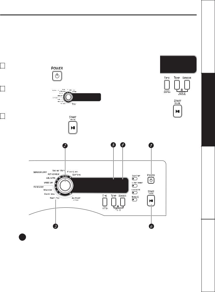
Quick Start
If the screen is dark, press the POWER button to “wake up” the display.
1 Press the POWER button.
2 Select a cycle by turning the
Cycle Knob.
3 If you selected a SENSOR DRY F\FOH³ just press the START/PAUSE button.
If you selected a TIME DRY
F\FOH³VHOHFW\RXUKHDWVHWWLQJ and the amount of time you want your items to dry by pressing the TIME button until the desired time appears in
the display. Then press the START/ PAUSE button.
1 Power
Press to “wake up” the display. If the display is active, press to turn the dryer off.
NOTE: Pressing POWER does not disconnect the appliance from the power supply.
5
Instructions Safety
Instructions Operating
Tips Troubleshooting
Support Consumer
Safety Instructions
Operating Instructions
Troubleshooting Tips
Consumer Support
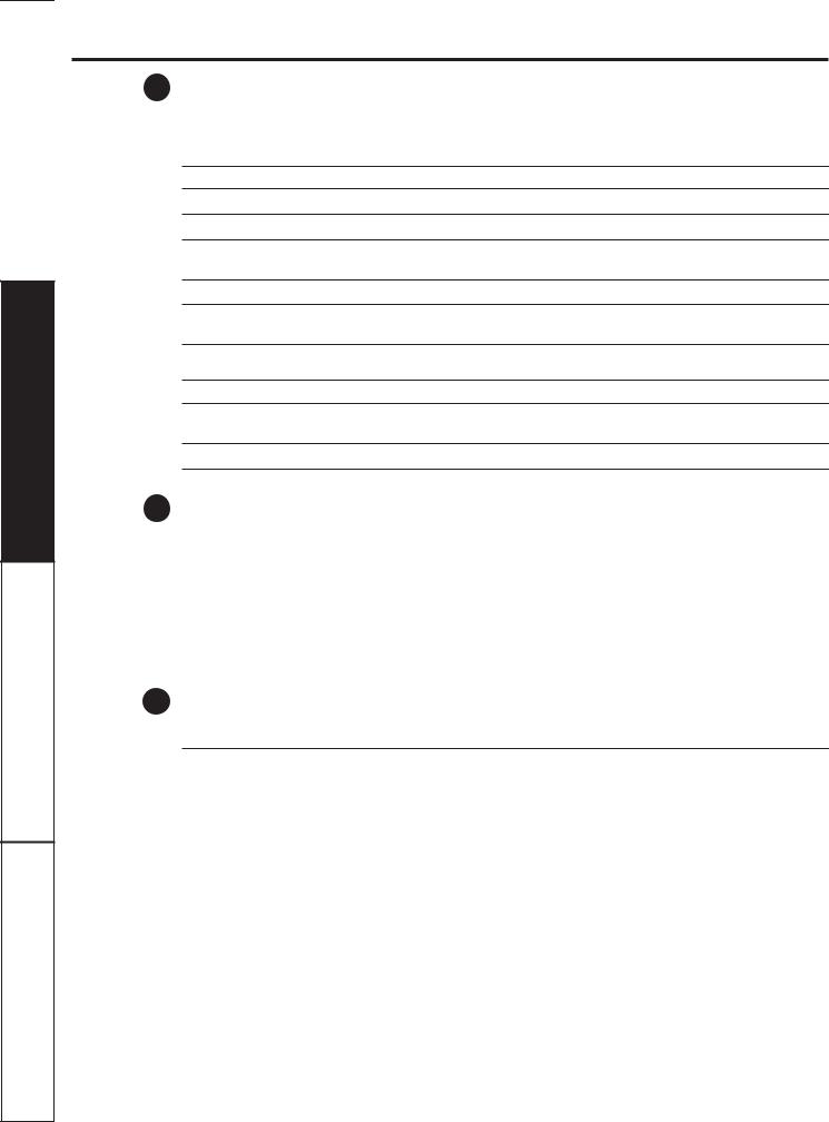
About the dryer control panel.
2 Dry Cycles
The dry cycle controls the cycle time for the drying process. The chart below will help you match the dry setting with the loads.
Sensor Cycles
COTTONS For cottons and most linens.
MIXED LOAD For loads consisting of cottons and poly blends.
WRINKLE FREE For wrinkle-free/easy care and permanent press items.
ACTIVE WEAR Clothing worn for active sports exercise and some casual wear. Fabrics include new technology finishes and stretch fibers such as spandex.
DELICATES For lingerie and special-care fabrics.
SPEED DRY For small loads that are needed in a hurry, such as sports or school uniforms. Can also be used if the previous cycle left some items damp, such as collars or waistbands.
Time Dry Cycles
WARM UP Provides 10 minutes of warming time to warm up clothes.
DEWRINKLE For removing wrinkles from items that are dry or slightly damp. This cycle is not recommended for delicate fabrics.
AIR FLUFF Use this feature to tumble items without heat.
3 Timed Dry
Use to set your own dry time. TIMED DRY is also recommended for small loads.
To use TIMED DRY:
1.Turn dry cycle dial to TIMED DRY.
2.Select the drying time by pressing the TIME button. You can increase the time in 10-minute increments up to 1 hour and 20 minutes.
3.Select the DRY TEMP.
4.Close the door.
5.Press START/PAUSE.
4 |
Sensor Dry Level |
The sensor continuously monitors the amount of moisture in the load. When the moisture in your |
|
|
clothes reaches your selected dry level, the dryer will stop. |
EXTRA DRY |
Use for heavy-duty fabrics or items that should be very dry, such as towels. |
MORE DRY |
Use for heavy or mixed type of fabrics. |
|
|
DRY |
Use for normal dryness level suitable for most loads. This is the preferred cycle |
|
for energy saving. |
LESS DRY |
Use for lighter fabric (ideal for ironing). |
|
|
DAMP |
For leaving items partially damp. |
|
|
NOTE: The Sensor Dry Levels can only be selected in a Sensory Dry Cycle.
6
GEAppliances.com
5 |
Dry Temp |
|
You can change the temperature of your dry cycle. |
ANTI-BACTERIAL This option may only be used with COTTONS or MIXED LOAD cycles. This option reduces certain types of bacteria. The anti-bacterial process occurs when high heat is used during a portion of this drying cycle.
NOTE: Do not use this cycle on delicate fabrics.
HIGH For regular to heavy cottons.
MEDIUM For synthetics, blends and items labeled permanent press.
LOW For delicates, synthetics and items labeled Tumble Dry Low.
EXTRA LOW For lingerie and special-care fabrics.
6 START/PAUSE
Press to start a dry cycle. If the dryer is running, press it once and it will pause the dryer. Press it again to restart the dry cycle.
“CLEAN LINT FILTER” (message)
This message stays on until the START button is pressed. This message is only a reminder.
7
Instructions Safety
Instructions Operating
Tips Troubleshooting
Support Consumer
Safety Instructions
Operating Instructions
Troubleshooting Tips
Consumer Support
About cycle options.
NOTE: Not all features are available on all dryer models.
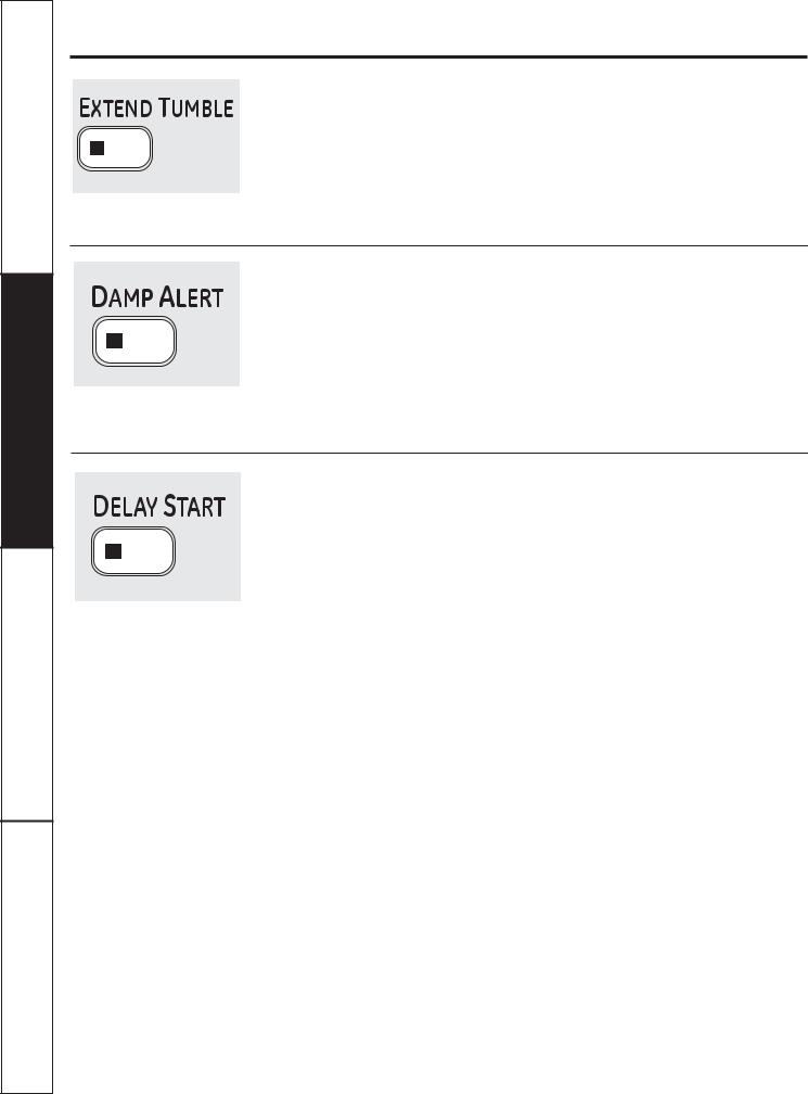
Extend Tumble
Minimizes wrinkles by adding approximately 20 minutes of constant no-heat tumbling followed by 70 minutes of intermittent no-heat tumbling after clothes are dry. The dryer is in EXTENDED TUMBLE when the ESTIMATED CYCLE TIME display is illuminated in a circular pattern.
The light in the button will light up when
EXTEND TUMBLE is on.
NOTE: It is normal for the drum to pause for short periods of time during EXTEND TUMBLE.
Damp Alert
This option causes the dryer to beep when clothes have dried to a damp level. Remove items that you wish to hang dry. The
DAMP ALERT will only beep when this option is selected (dry cycle keeps running).
Removing clothes and hanging them when they are damp can reduce the need to iron some items.
The light in the button will light up when
DAMP ALERT is on.
NOTE: Only for DRY, MORE DRY and EXTRA DRY sensor dry selections.
Delay Start
Use to delay the start of your dryer.
1.Choose your dry cycle and any options.
2.Press the DELAY START button. You can change the delay time in 1-hour increments (up to 18 hours) each time
you press the DELAY START button. Stop pressing the button when your desired time is displayed.
3.Press the START/PAUSE button to start the countdown.
NOTES:
If the door is opened while the dryer is in DELAY, the countdown time will continue to count down the delay time. If the door is not closed and the countdown time expires, the cycle will not start until the door is closed and the START/PAUSE button is pressed.
You can delay the start of a dryer cycle up to 18 hours.
The countdown time will be shown in the |
The light in the button will light up when |
ESTIMATED TIME REMAINING display. |
DELAY START is on. |
8
GEAppliances.com
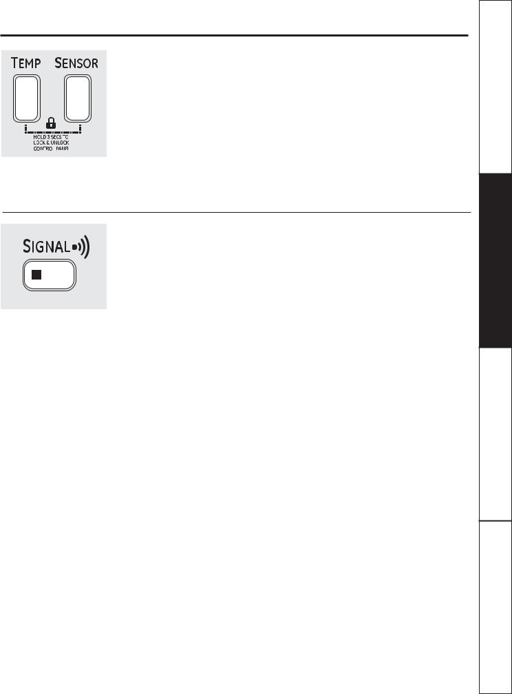
Lock
You can lock the controls to prevent any selections from being made. Or you can lock or unlock the controls after you have started a cycle.
Children cannot accidentally start the dryer by touching pads with this option selected.
To lock the dryer, press and hold
the TEMP and SENSOR buttons together for 3 seconds.
To unlock the dryer controls, press
and hold the TEMP and SENSOR buttons together for 3 seconds. A sound will indicate the lock/unlock status.
The control lock icon on the display will light up when it is on.
NOTE: The POWER button can still be used when the machine is locked.
Signal
When the light is “on,” the dryer will beep at the end of the cycle and every time you press a button on the control panel.
To turn the signal off, press the SIGNAL button and the light will go off.
9
Instructions Safety
Instructions Operating
Tips Troubleshooting
Support Consumer

Safety Instructions
Operating Instructions
Troubleshooting Tips
Consumer Support
Using the dryer.
Always follow fabric manufacturer’s care label when laundering.
Sorting and Loading Hints
As a general rule, if clothes are sorted properly for the washer, they are sorted properly for the dryer. Try also to sort items according to size. For example, do not dry a sheet with socks or other small items.
Do not add fabric softener sheets once the load has become warm. They may cause fabric softener stains. Bounce® Fabric Conditioner Dryer Sheets have
been approved for use in this dryer when used in accordance with the manufacturer’s instructions.
See below for lint filter cleaning instructions.
Do not overload. This wastes energy and causes wrinkling.
Do not dry the following items: fiberglass items, woolens, rubber-coated items, plastics, items with plastic trim and foam-filled items.
Fabric Care Labels
Below are fabric care label “symbols” that affect the clothing you will be laundering.
Dry Labels
Tumble |
|
|
|
|
|
|
dry |
|
|
|
|
|
Do not dry |
Dry |
Normal |
|
|
|
|
|
Permanent Press/ |
Gentle/ |
Do not tumble dry (used with |
||||
|
|
wrinkle resistant |
delicate |
do not wash) |
||
Heat setting
High Medium Low No heat/air
Special instructions
Line dry/ |
Drip dry |
Dry flat |
In the shade |
hang to dry |
|
|
|
Care and Cleaning of the Dryer
Dryer Interior and Duct: The interior of the appliance and exhaust duct should be cleaned once a year by qualified service personnel.
The Exterior: Wipe or dust any spills or washing compounds with a damp cloth. Dryer control panel and finishes may be damaged by some laundry pretreatment soil and stain remover products. Apply these products away from the dryer. The fabric may then be washed and dried normally. Damage to your dryer caused by these products is not covered by your warranty.
Do not touch the surface or the display with sharp objects.
|
The Lint Filter: Clean the lint filter before |
|
each use. Remove by pulling straight up. |
|
Open the filter and run your fingers across |
|
the filter. A waxy buildup may form on the |
|
lint filter from using dryer-added fabric |
10 |
softener sheets. To remove this buildup, |
wash the lint screen in warm, soapy |
water. Dry thoroughly and replace. Do not operate the dryer without the lint filter
in place.
Vacuum the lint from the dryer lint filter if you notice a change in dryer performance.
Stainless Steel: To clean stainless steel surfaces, use a damp cloth with a mild, nonabrasive cleaner suitable for stainless steel surfaces. Remove the cleaner residue, and then dry with a clean cloth.
The stainless steel used to make the dryer drum provides the highest reliability available in a GE dryer. If
the dryer drum should be scratched or dented during normal use, the drum will not rust or corrode. These surface blemishes will not affect the function or durability of the drum.
The Exhaust Hood: Check with a mirror that the inside flaps of the hood move freely when operating. Make sure that there is no wildlife (birds, insects, etc.) nesting inside the duct or hood.
|
Installation |
|
Dryer |
|
|
Instructions |
DCVH480EK, DCVH485EK, PCVH480EK, PCVH485EK |
||
|
|
|
|
|
|
|
|
|
|
|
|
|
|
|
|
Questions? Call 800.GE.CARES (800.432.2737) or visit our Website at: GEAppliances.com |
|
|
|
|
In Canada, call 1.800.561.3344 or visit www.GEAppliances.ca |
|
|
|
|
|
|
|
|
If you are planning to stack the washer and dryer, order Stacking Kit number GE24STACK to be used for this dryer. Kit sold separately.
BEFORE YOU BEGIN
Read these instructions completely and carefully.
• IMPORTANT – Save these instructions for local
electrical inspector’s use.
• IMPORTANT – Observe all governing codes and ordinances.
•Install the clothes dryer according to the manufacturer’s instructions and local codes.
•Note to Installer – Be sure to leave these instructions with the Consumer.
•Note to Consumer – Keep these instructions for future reference.
•Clothes dryer installation must be performed by a qualified installer.
•This dryer must be exhausted to the outdoors.
•Before the old dryer is removed from service or discarded, remove the dryer door.
•Service information and the wiring diagram are located in the control console.
•Do not allow children on or in the appliance. Close supervision of children is necessary when the appliance is used near children.
•Proper installation is the responsibility of the installer.
•Product failure due to improper installation is not covered under the Warranty.
•Install the dryer where the temperature is above 50°F for satisfactory operation of the dryer control system.
•Remove and discard existing plastic or metal foil duct and replace with UL-listed duct.
FOR YOUR SAFETY:
 WARNING – Risk of Fire
•To reduce the risk of severe injury or death, follow all installation instructions.
•Clothes dryer installation must be performed by a qualified installer.
•Install the clothes dryer according to these instructions and in accordance with local codes.
•This dryer must be exhausted to the outdoors.
•Use only 4” rigid metal ducting for exhausting the clothes dryer to the outdoors.
•DO NOT install a clothes dryer with flexible plastic ducting materials. If flexible metal (semi-rigid or foil-type) duct is installed, it must be UL-listed and installed in accordance with the instructions found in “Connecting the Dryer to House Vent” on page 18 of this manual. Flexible ducting materials are known to collapse, be easily crushed and trap lint. These conditions will obstruct dryer airflow and increase the risk of fire.
•Do not install or store this appliance in any location where it could be exposed to water and/or weather.
•The National Fuel Gas Code restricts installations of gas appliances in garages. They must be 18 inches off the ground and protected by a barrier from vehicles.
•Save these instructions. (Installers: Be sure to leave these instructions with the customer.)
11
Installation Instructions
UNPACKING YOUR DRYER
Tilt the dryer sideways and remove the foam shipping pads by pulling at the sides and breaking them away from the dryer legs. Be sure to remove all of the foam pieces around the legs.
Remove the bag containing the literature.
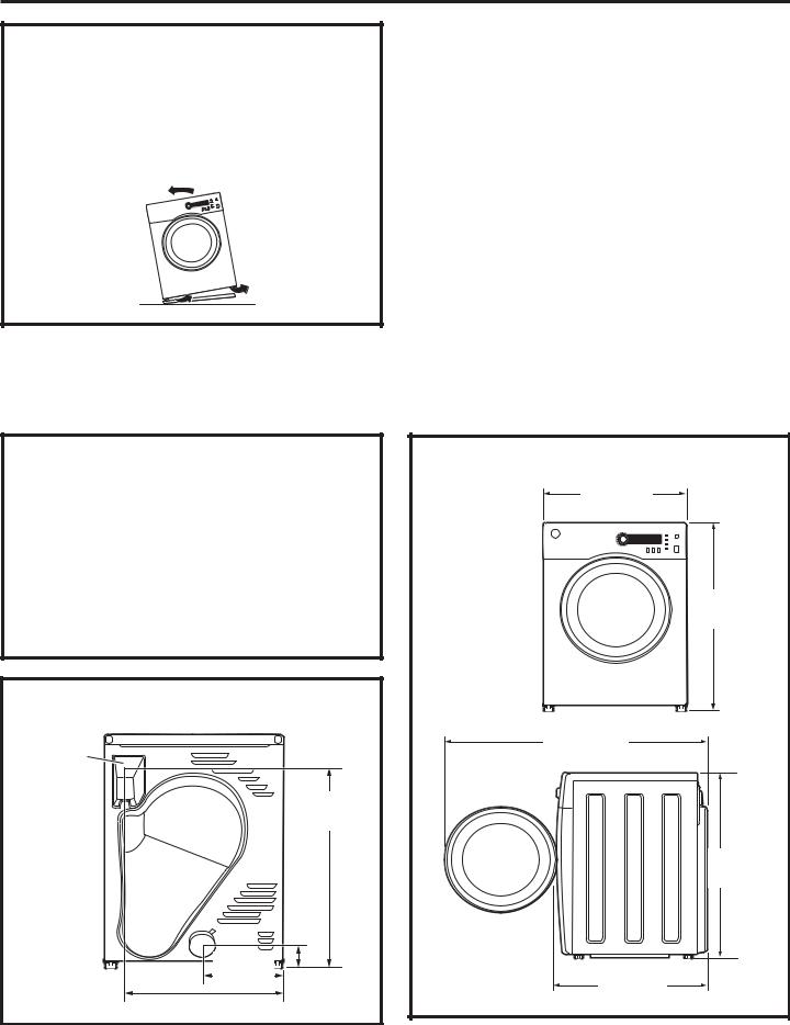
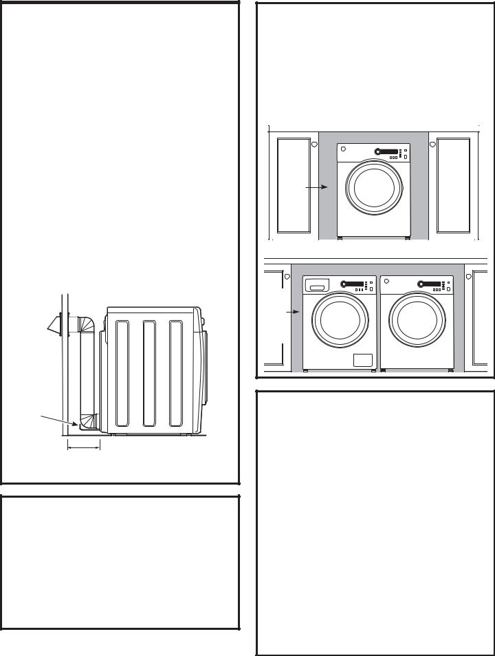
LOCATION OF YOUR DRYER
MINIMUM CLEARANCE OTHER THAN ALCOVE OR CLOSET INSTALLATION
Minimum clearance to combustible surfaces and for air openings are:
•0 inch clearance both sides
•3 inches front and rear
Consideration must be given to provide adequate clearance for proper operation and service.
ELECTRICAL CONNECTION
Electrical |
|
Connection |
|
|
27.65” |
Back View |
(702 mm) |
10.0” |
4.0” |
(254mm) |
|
20.75” (527 mm) |
(101 mm) |
|
DRYER DIMENSIONS |
23.5” |
(598 mm) |
Front View |
33.4” |
(848 mm) |
42.9” |
(1090 mm) |
33.4” |
(848 mm) |
Side View |
25.7” |
(653 mm) |
12
Installation Instructions
REQUIREMENTS FOR ALCOVE OR CLOSET INSTALLATION
•Your dryer is approved for installation in an alcove or closet, as stated on a label on the dryer back.
•The dryer MUST be vented to the outdoors. See the EXHAUSTING THE DRYER section.
•Minimum clearance between dryer cabinet and adjacent walls or other surfaces is:
0” either side
3” front and rear
•Minimum vertical space from floor to overhead shelves, cabinets, ceilings, etc., is 52”.
•Closet doors must be louvered or otherwise ventilated and have at least 60 square inches of open area equally distributed. If the closet contains both a washer and a dryer, doors must
contain a minimum of 120 square inches of open area equally distributed.
NOTE: WHEN THE EXHAUST DUCT IS LOCATED AT THE REAR OF THE DRYER, MINIMUM CLEARANCE FROM THE WALL IS 5.5 INCHES.
Wire frame spacer
5.5” (140 mm)
BATHROOM OR BEDROOM
INSTALLATION
•The dryer MUST be vented to the outdoors. See EXHAUSTING THE DRYER.
•The installation must conform with local codes or, in the absence of local codes, with the NATIONAL ELECTRICAL CODE, ANSI/NFPA NO. 70 (for electric dryers) or NATIONAL FUEL GAS CODE, ANSI Z223 (for gas dryers).
UNDERCOUNTER INSTALLATION
If an undercounter installation is desired:
• No special dryer installation kit is required.
• If the dryer is installed alone, a minimum of 60 square inches of open area is required. If a washer and dryer are installed together,
a minimum of 120 square inches of open area
is required.
Dryer installed alone
60 |
square |
inches |
min. |
open |
area |
Washer and Dryer installed together
Countertop and side cabinets
120 |
square |
inches |
min. |
open |
area |
MOBILE OR MANUFACTURED HOME INSTALLATION
•The installation must conform to the MANUFACTURED HOME CONSTRUCTION & SAFETY STANDARD, TITLE 24, PART 32–80 or, when such standard is not applicable, with AMERICAN NATIONAL STANDARD FOR MOBILE HOME,
NO. 501B.
•The dryer MUST be vented to the outdoors with the termination securely fastened to the mobile home structure. (See EXHAUSTING THE DRYER.)
•The vent MUST NOT be terminated beneath a mobile or manufactured home.
•The vent duct material MUST BE METAL.
•Do not use sheet metal screws or other refastening devices which extend into the interior of the exhaust vent.
•Provide an opening with a free area of at least 25 sq. in. for introduction of outside air into the dryer room.
13
Installation Instructions
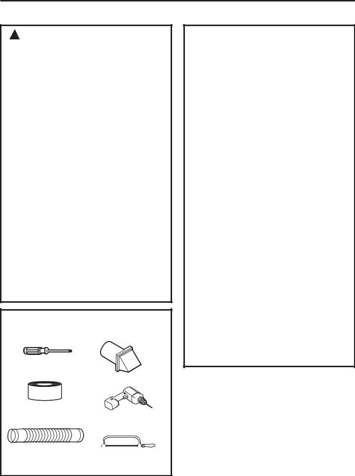
CONNECTING AN ELECTRIC DRYER
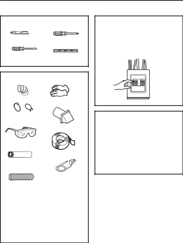
TOOLS YOU WILL NEED
Slip joint pliers |
Phillips screwdriver |
Flat-blade |
Level |
screwdriver |
|
MATERIALS YOU WILL NEED
4” dia. metal elbow |
Gloves |
4” duct clamps (2) or 4” spring clamps (2)
Exhaust hood
Safety glasses
Duct tape
4”-dia. metal duct (recommended)
|
Dryer power cord kit |
|
6 ft. long (not |
4”-dia., UL-listed |
provided with dryer) |
UL-rated 120/240V, |
|
flexible metal duct (if |
30A with 3 or 4 prongs. |
needed) |
Identify the plug type as |
|
per the house receptacle |
|
before purchasing line |
|
cord. (4-prong cord set |
|
is included and installed |
|
on Canadian models |
|
PCVH480 and PCVH485.) |
|
Stacking installations |
|
may require a power |
|
cord up to 6 feet in |
|
length. |
14
FOR YOUR SAFETY:
 WARNING
Before making the electrical connection, turn off the circuit breaker(s) or remove the dryer’s circuit fuse(s) at the electrical box. Be sure the dryer cord is unplugged from the wall. NEVER LEAVE THE ACCESS COVER OFF THE TERMINAL BLOCK.
ELECTRICAL CONNECTION INFORMATION FOR ELECTRIC DRYERS
 WARNING – To reduce the risk of fire, electrical shock and personal injury:
•Do not use an extension cord or an adapter plug with this appliance.
•The dryer must be electrically grounded in accordance with local codes and ordinances or, in the absence of local codes, in accordance with the NATIONAL ELECTRICAL CODE, ANSI/NFPA NO. 70.
Installation Instructions
ELECTRICAL REQUIREMENTS FOR ELECTRIC DRYERS
This dryer must be connected to an individual branch circuit, protected by the required time-delay fuses or circuit breakers. A threeor four-wire, single-phase, 120/240V or 120/208V, 60Hz, 30-amp circuit is required.
If the electric supply does not meet the above specifications, then call a licensed electrician.
NOTE: For Canadian consumers with models PCVH480 and PCVH485, cord set installation is not required. Please skip to the next section, Exhausting the Dryer.
GROUNDING INSTRUCTIONS
This dryer must be connected to a grounded metal, permanent wiring system, or an equipmentgrounding conductor must be run with the circuit conductors and connected to the equipmentgrounding terminal on the appliance.
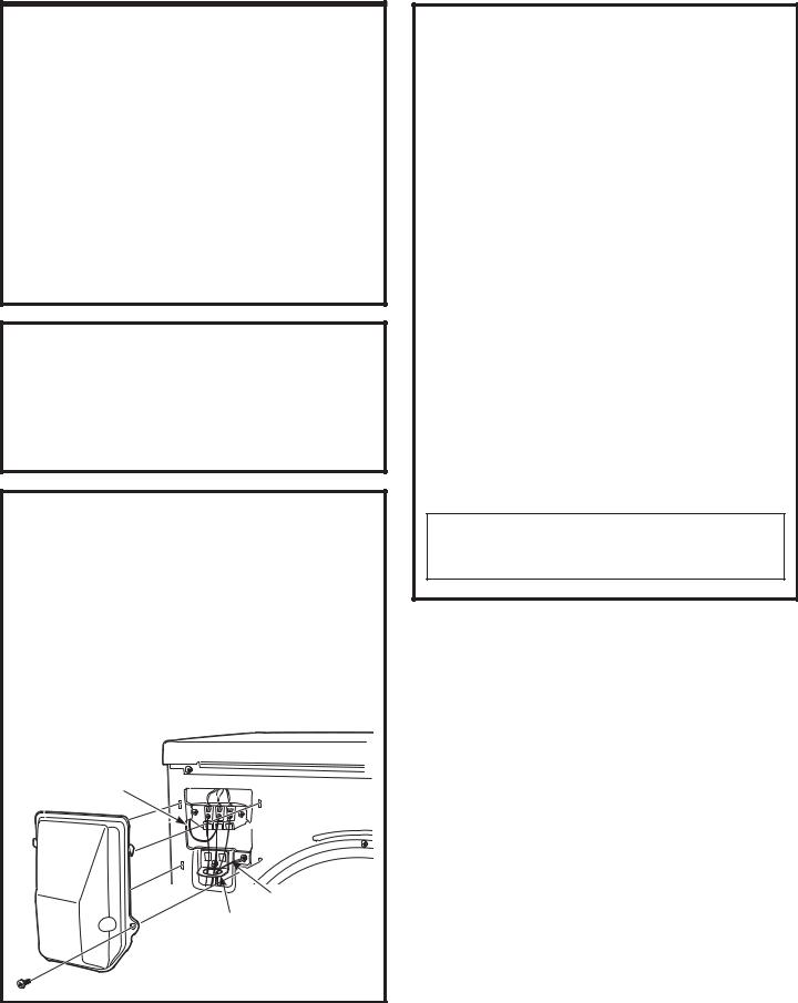
CONNECTING DRYER USING 4-WIRE CONNECTION (MUST BE USED FOR MOBILE HOME INSTALLATION)
NOTE: Since January 1, 1996, the National Electrical Code requires that new constructions utilize a 4-wire connection to an electric dryer.
A 4-wire cord must also be used where local codes do not permit grounding through the neutral.
3-wire connection is NOT for use on new construction.
Ground strap
|
Green wire from |
Bracket |
power cord |
|
15
CONNECTING DRYER USING 4-WIRE CONNECTION (MUST BE USED FOR MOBILE HOME INSTALLATION) (cont.)
1.Turn off the circuit breaker(s) (30 amp) or remove the dryer’s circuit fuse at the electrical box.
2.Be sure the dryer cord is unplugged from the wall receptacle.
3.Remove the power cord cover located at the upper back.
4.Remove the green ground screw and attach the ground strap to the center terminal along with the (white) neutral line described below. Keep the green ground screw for Step 7.
5.Bring the power cord through the bracket.
6.Connect power cord as follows:
A.Connect the 2 hot lines to the outer screws of the terminal block (marked L1 and L2).
B.Connect the neutral (white) line to the center of the terminal block (marked N).
7.Attach ground wire of power cord with the green ground screw (hole above strain relief bracket). Tighten all terminal block screws (3) completely.
8.Reinstall the cover.
 WARNING – NEVER LEAVE THE COVER OFF OF THE TERMINAL BLOCK.
Installation Instructions
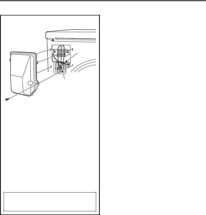
CONNECTING AN ELECTRIC DRYER (cont.)
CONNECTING DRYER USING 3-WIRE
CONNECTION
Ground strap 
Bracket
1.Turn off the circuit breaker(s) (30 amp) or remove the dryer’s circuit fuse at the electrical box.
2.Be sure the dryer cord is unplugged from the wall receptacle.
3.Remove the power cord cover located at the upper back.
4.Bring the power cord through the bracket.
5.Connect power cord as follows:
A.Connect the 2 hot lines to the outer screws of the terminal block (marked L1 and L2).
B.Connect the neutral (white) line to the center of the terminal block (marked N).
6.Be sure ground strap is connected to green ground screw on cabinet rear. Tighten all terminal block screws (3) completely.
7.Reinstall the cover.
 WARNING – NEVER LEAVE THE
COVER OFF OF THE TERMINAL BLOCK.
16
Installation Instructions
EXHAUSTING THE DRYER
 WARNING – To reduce the risk of fire or personal injury:
•This clothes dryer must be exhausted to the outdoors.
•Use only 4” rigid metal ducting for the home exhaust duct.
•Use only 4” rigid metal or UL-listed flexible metal (semi-rigid or foil-type) duct to connect the dryer to the home exhaust duct. It must be installed in
accordance with the instructions found in “Connecting the Dryer to House Vent” on page 18 of this manual.
•Do not terminate exhaust in a chimney, a wall, a ceiling, gas vent, crawl space, attic, under an enclosed floor, or in any other concealed space of a building.
•Never terminate the exhaust into a common duct with a kitchen exhaust system. A combination of grease and lint create a potential fire hazard.
•Do not use duct longer than specified in the exhaust length table. Longer ducts can accumulate lint, creating a potential fire hazard.
•Never install a screen in or over the exhaust duct. This will cause lint to accumulate, creating a potential fire hazard.
•Do not assemble ductwork with any fasteners that extend into the duct. These fasteners can accumulate lint, creating a potential fire hazard.
•Do not obstruct incoming or exhausted air.
•Provide an access for inspection and cleaning of the exhaust system, especially at turns and joints. Exhaust system shall be inspected and cleaned at least once a year.
•This dryer comes ready for rear exhausting. If space is limited, use the instructions on pages 21–23 to exhaust directly from the sides or bottom of the cabinet.
TOOLS AND MATERIALS YOU WILL NEED TO INSTALL EXHAUST DUCT
Phillips-head screwdriver
Vent hood
Duct tape or duct  clamp Drill with 1/8” drill bit
(for bottom venting)
Rigid or UL-listed  flexible metal 4” (10.2 Hacksaw
cm) duct
17
EXHAUST SYSTEM CHECKLIST
HOOD OR WALL CAP
•Terminate in a manner to prevent back drafts or entry of birds or other wildlife.
•Termination should present minimal resistance to the exhaust airflow and should require little or no maintenance to prevent clogging.
•Never install a screen in or over the exhaust duct.
•Wall caps must be installed at least 12” above ground level or any other obstruction with the opening pointed down.
SEPARATION OF TURNS
•For best performance, separate all turns by
at least 4 ft. of straight duct, including distance between last turn and dampened wall cap. For turns less than 4 ft. apart, see the Ducting Component Equivalency Chart.
SEALING OF JOINTS
•All joints should be tight to avoid leaks. The male end of each section of duct must point away from the dryer.
•Do not assemble the ductwork with fasteners that extend into the duct. They will serve as a collection point for lint.
•Duct joints should be made airand moisture-tight by wrapping the overlapped joints with duct tape or aluminum tape.
•Horizontal runs should slope down towards outdoors 1/4” per foot.
INSULATION
•Ductwork that runs through an unheated area or is near air conditioning should be insulated to reduce condensation and lint buildup.

Installation Instructions
EXHAUSTING THE DRYER (cont.)
CONNECTING THE DRYER TO
HOUSE VENT
RIGID METAL TRANSITION DUCT
•For best drying performance, a rigid metal transition duct is recommended.
•Rigid metal transition ducts reduce the risk of crushing and kinking.
UL-LISTED FLEXIBLE METAL (SEMI-RIGID) TRANSITION DUCT
•If rigid metal duct cannot be used, then UL-listed flexible metal (semi-rigid) ducting can be used (Kit WX08X10077).
•Never install flexible metal duct in walls, ceilings, floors or other enclosed spaces.
•Total length of flexible metal duct should not exceed 8 feet (2.4 m).
•For many applications, installing elbows at both the dryer and the wall is highly recommended (see illustrations at right). Elbows allow the dryer to sit close to the wall without kinking and/or crushing the transition duct, maximizing drying performance.
•Avoid resting the duct on sharp objects.
UL-LISTED FLEXIBLE METAL (FOIL-TYPE)
TRANSITION DUCT
•In special installations, it may be necessary to connect the dryer to the house vent using a flexible metal (foil-type) duct. A UL-listed flexible metal (foil-type) duct may be used ONLY in installations where rigid metal or flexible metal (semi-rigid) ducting cannot be used AND where a 4” diameter can be maintained throughout the entire length
of the transition duct.
•In Canada and the United States, only the flexible metal (foil-type) ducts that comply with the “Outline for Clothes Dryer Transition Duct, Subject 2158A” shall be used.
•Never install flexible metal duct in walls, ceilings, floors or other enclosed spaces.
•Total length of flexible metal duct should not exceed 8 feet (2.4 m).
•Avoid resting the duct on sharp objects.
•For best drying performance:
1.Slide one end of the duct over the clothes dryer outlet pipe.
2.Secure the duct with a clamp.
3.With the dryer in its permanent position, extend the duct to its full length. Allow 2” of duct to overlap the exhaust pipe. Cut off and remove excess duct. Keep the duct as straight as possible for maximum airflow.
4.Secure the duct to the exhaust pipe with the other clamp.
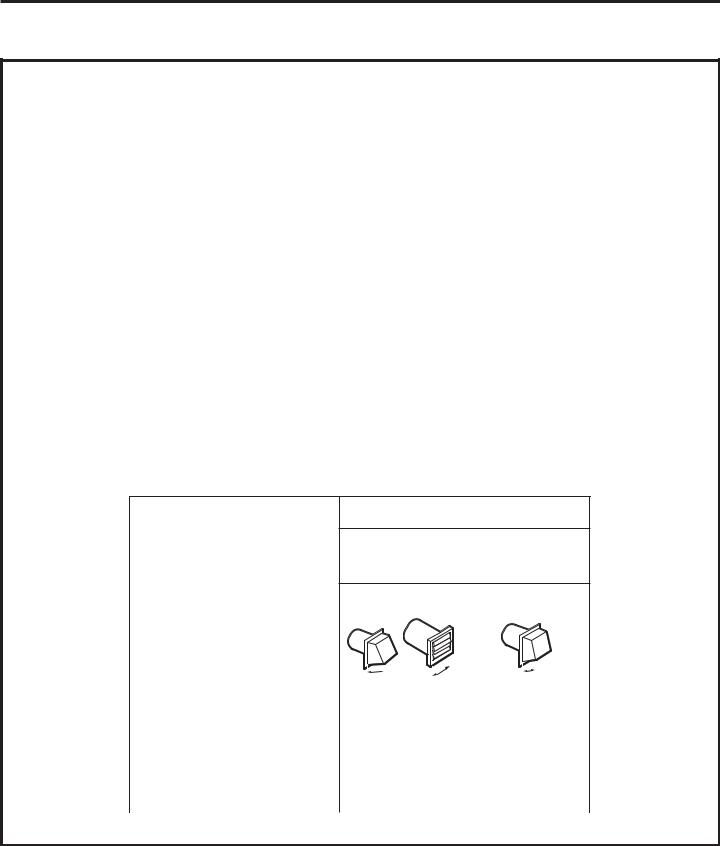
FOR TRANSITION VENTING (DRYER TO WALL), DO:
•DO cut duct as short as possible and install straight into wall.
•DO use elbows when turns are necessary.
Elbows
DO NOT:
•DO NOT bend or collapse ducting. Use elbows
if turns are necessary.
•DO NOT use excessive exhaust length. Cut duct as short as possible.
•DO NOT crush duct against the wall.
•DO NOT set dryer on duct.
18
Installation Instructions
 WARNING
USE ONLY METAL DUCT 4” DIAMETER (102 mm FOR CANADA). DO NOT USE DUCT LONGER THAN SPECIFIED IN THE EXHAUST LENGTH TABLE.
'U\HU ([KDXVWLQJ ,QIRUPDWLRQ³0HWDO 'XFW 2QO\
Ducting Materials: For best performance, this dryer should be vented with 4” diameter all-rigid metal exhaust duct.
Exhaust Length Calculation:
1.Determine the number of 90º turns needed for your installation.
2.The maximum length of 4’ rigid (aluminum or galvanized) duct which can be tolerated is shown in the table.
A turn of 45º or less may be ignored. Two 45º turns within the duct length should be treated as a 90º elbow.
A turn over 45º should be treated as a 90º elbow.
 CAUTION: For personal safety, do not terminate exhaust into a chimney, under any
enclosed house floor (crawl space), or into an attic, since the accumulated lint could create a fire hazard or moisture could cause damage. Never terminate the exhaust into a common duct or plenum with a kitchen exhaust, since the combination of lint and grease could create a fire hazard.
Exhaust ducts should be terminated in a dampered wall cap to prevent back drafts, bird nesting, etc. The wall cap must also be located at least 12” above the ground or any other obstruction with
the opening pointed down.
Other terminations, such as louvered wall boxes, are acceptable provided they are equivalent to a 4” opening dampered wall cap.
For more information on venting kits and accessories, please call 1.800.GE.CARES.
Best Performance
Maximum Length
of a 4” Dia.
Rigid Metal Duct
Exhaust Hood Type
|
|
|
|
|
|
2 |
|
|
|
|
|
|
|
|
|
|
|
|
|
|
|
|
|
|
|
|
|
|
4” |
4” |
-1/2” |
||||
Number of |
|
A |
|
|
|
B |
||
90º Turns |
4” Opening |
|
|
2-1/2” Opening |
||||
Front-Loading Dryers 0 |
|
90 ft. |
|
|
60 ft. |
|||
1 |
|
|
60 ft. |
|
|
45 ft. |
||
2 |
|
|
45 ft. |
|
|
35 ft. |
||
3 |
|
|
35 ft. |
|
|
25 ft. |
||
|
|
|
|
|
|
|
|
|
19
Installation Instructions
EXHAUSTING THE DRYER (cont.)
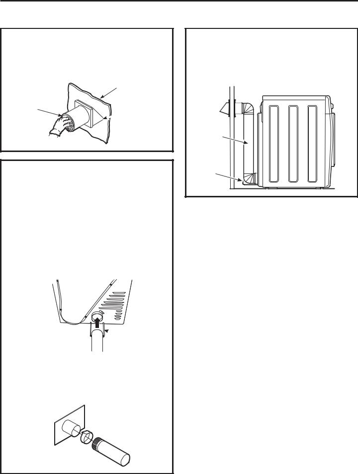
BEFORE YOU BEGIN
•Remove and discard existing plastic or metal duct and replace with UL-listed duct.
•Remove any lint from the wall exhaust opening.
Wall
Internal duct opening
 Check that exhaust hood damper opens and closes freely.
STANDARD REAR EXHAUST
We recommend that you install your dryer before installing your washer. This will permit direct access for easier exhaust connection.
Pull out the wire spacer and swing upward to its full extension. Let the wire spacer lay flat and extended on the floor. This will prevent the dryer from being pushed too close to a wall or object, causing the ducting to come loose from the dryer.
Slide the end of the exhaust duct on the back of the dryer and secure with duct tape or a hose clamp.
 Wire frame spacer
Duct
NOTE: We strongly recommend using rigid metal exhaust duct.
•For straight-line installation, connect the dryer exhaust to the wall, using duct tape.
RECOMMENDED CONFIGURATION TO MINIMIZE EXHAUST BLOCKAGE
Using duct elbows will prevent duct kinking and collapsing.
Transition ducting
Wire frame spacer
Wall side
Dryer side
20
Installation Instructions
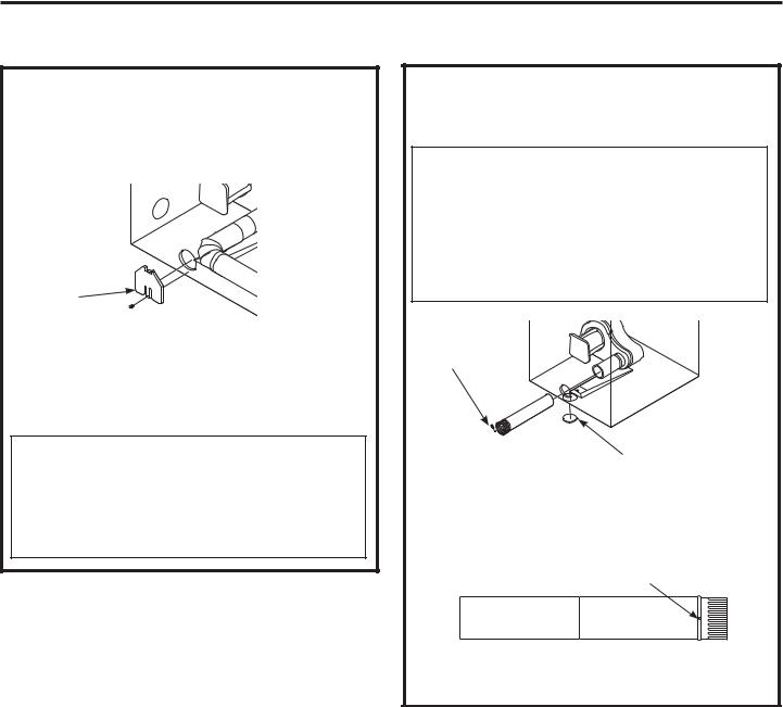
SIDE VENTING:
Dryer Exhaust to side of cabinet
 WARNING – BEFORE
PERFORMING THIS EXHAUST INSTALLATION, BE SURE TO DISCONNECT THE DRYER FROM ITS ELECTRICAL SUPPLY. PROTECT YOUR HANDS AND ARMS FROM SHARP EDGES WHEN WORKING INSIDE THE CABINET. BE SURE TO WEAR GLOVES.
Remove Right screw and  save
save
Left
Bottom
Remove desired knockout (one only)
Detach and remove the bottom, right or left side knockout as desired. Remove the screw from the rear of the casing and save. Pull the duct out of the dryer.
Fixing hole |
|
Tab |
|
|
|
|
|
|
A
 4.9” (125 mm)

Cut the duct as shown and keep portion A.
ADDING A NEW DUCT
Fixing hole |
Portion “A” |
Left side 
 exhaust

Reconnect the cut portion (A) of the duct to the blower housing. Make sure that the screw holes in the duct and ramp base are aligned. Use the screw saved previously to secure the duct in place through the ramp on the appliance base.
ADDING ELBOW AND DUCT FOR EXHAUST TO LEFT OR RIGHT SIDE OF CABINET
•Tape the connection between the duct and elbow.
•Insert the duct with elbow through the rear opening and connect to the internal duct.
 CAUTION: Be sure not to pull or damage the electrical wires inside the dryer when inserting the duct. A slight interference may occur between the exhaust and the wire components.
• Apply duct tape as shown on the joint between the dryer internal duct and the elbow, and also the joint between the
elbow and the side duct.
 CAUTION: Internal duct joints must be secured with tape; otherwise, they may separate and cause a safety hazard.
21
Installation Instructions
EXHAUSTING THE DRYER (cont.)
SIDE VENTING (cont.)
ADDING COVER PLATE TO REAR OF CABINET (SIDE EXHAUST)
Cover Plate
Connect standard metal elbows and ducts to complete the exhaust system. Cover back opening with a cover plate (Cover Plate – WE1M454) available from your local service provider. Place dryer in final location.
 WARNING – NEVER LEAVE THE BACK OPENING WITHOUT THE PLATE. COVER BACK OPENING WITH A COVER PLATE (COVER PLATE – WE1M454) AVAILABLE FROM YOUR LOCAL SERVICE PROVIDER.
BOTTOM VENTING:
Dryer Exhaust to the bottom of cabinet
 WARNING – BEFORE
PERFORMING THIS EXHAUST INSTALLATION, BE SURE TO DISCONNECT THE DRYER FROM ITS ELECTRICAL SUPPLY. PROTECT YOUR HANDS AND ARMS FROM SHARP EDGES WHEN WORKING INSIDE THE CABINET. BE SURE TO WEAR GLOVES.
Remove screw and save
Bottom
Remove desired knockout (one only)
Remove the screw inside the dryer exhaust duct and save. Pull the duct out of the dryer. Detach and remove the bottom knockout.
Fixing hole
A
 4.9” (125 mm)

Cut the duct as shown and keep portion A.
22

Installation Instructions
BOTTOM VENTING (cont.)
ADDING A NEW DUCT
• Reconnect the cut |
Portion “A” |
|
|
portion A of the |
|
duct to the blower Fixing hole |
|
housing. |
|
• Tape the elbow |
|
in a 90-degree |
|
position to |
|
prevent rotation. |
|
• Insert the elbow |
Rear hole |
through the rear hole |
|
and connect it to |
|
portion A. Rotate |
|
the elbow through |
Bottom |
the bottom opening. |
|
|
opening |
 CAUTION: Be sure not to pull or damage the electrical wires inside the dryer when inserting the duct.
•While still holding down the pipe and elbow from the rear opening, screw the pipes in place with
the previously saved screw.
• Apply duct tape |
Duct tape |
|
as shown on the joint |
||
|
||
between the dryer internal |
|
|
duct and the elbow. |
|
NOTE: Make sure the tape covers the screw hole in portion A where it connects
to the elbow.
 CAUTION: Internal duct joints must be secured with tape; otherwise, they may separate and cause a safety hazard.
Dryer Exhaust to the bottom of cabinet.
ADDING COVER PLATE TO REAR OF CABINET (BOTTOM EXHAUST)
Tab
Cover Plate 
Screw

Connect standard metal elbows and ducts to complete the exhaust system. Cover back opening with a cover plate (Cover Plate – WE1M454) available from your local service provider.
Insert the tab at the top of the cover plate into the opening. Fasten screw at the bottom of the cover plate.
Place dryer in final location.
 WARNING – NEVER LEAVE THE BACK OPENING WITHOUT THE PLATE. COVER BACK OPENING WITH A COVER PLATE (COVER PLATE – WE1M454) AVAILABLE FROM YOUR LOCAL SERVICE PROVIDER.
23
Installation Instructions
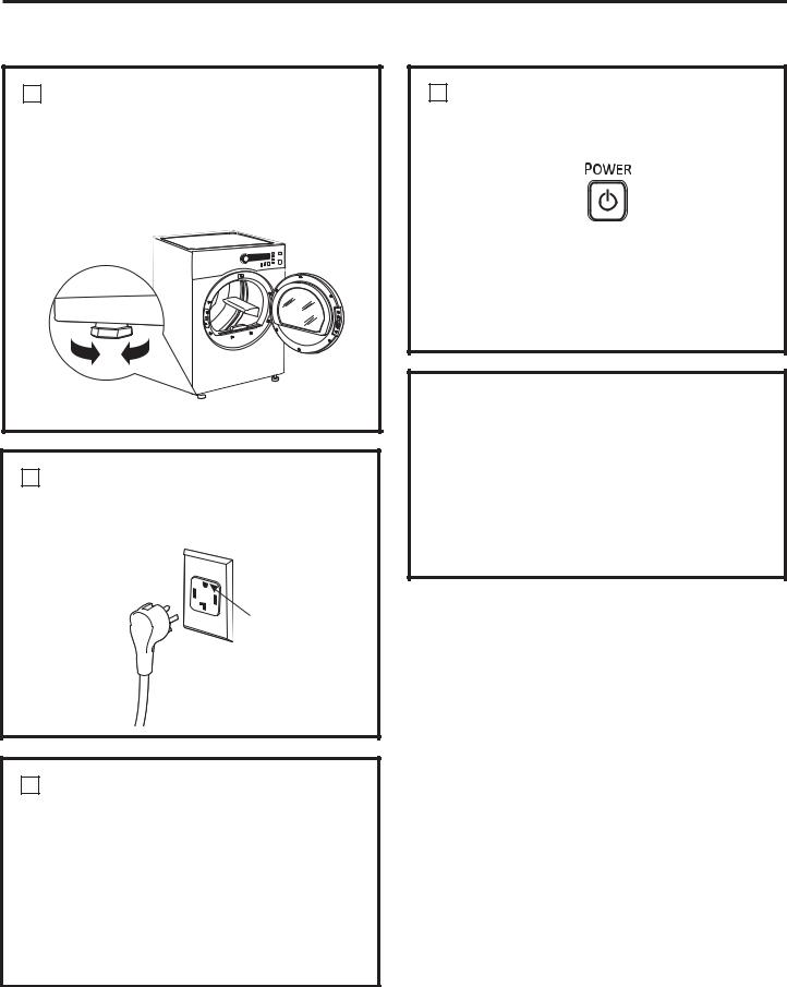
FINAL SETUP
1 LEVEL THE DRYER
Stand the dryer upright near the final location and adjust the four leveling legs at the corners to ensure that the dryer is level from side to side and front to rear.
Lower Raise 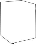
2 PLUG DRYER IN
NOTE: Stacking installations may require a power cord up to 6 feet in length.
Ensure proper ground exists before use.
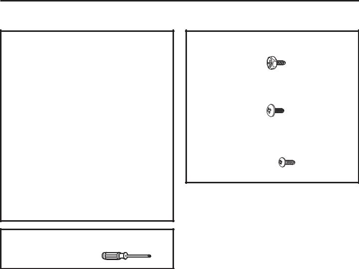
4 DRYER STARTUP
Press the POWER button.
NOTE: If the dryer has been exposed to temperatures below freezing for an extended period of time, allow it to warm up before pressing POWER. Otherwise, the display will not come on.
The dryer is now ready for use.
SERVICING
 WARNING – Label all wires prior to disconnection when servicing controls. Wiring errors can cause improper and dangerous operation after servicing/installation.
For replacement parts and other information, refer to the back cover for servicing phone numbers.
3 GROUNDING INSTRUCTIONS
This appliance must be grounded. In the event of malfunction or breakdown, grounding will reduce the risk of electric shock by providing a path of least resistance for electric current.
This appliance is equipped with a cord having an equipment-grounding conductor and a grounding plug. The plug must be plugged into an appropriate outlet that is properly installed and grounded in accordance with all local codes and ordinances.
24
Installation Instructions
REVERSING THE DOOR SWING (if desired)
IMPORTANT NOTES
•Read the instructions all the way through before starting.
•Handle parts carefully to avoid scratching paint.
•Provide a nonscratching work surface for the doors.
•Set screws down by their related parts to avoid using them in the wrong places.
•All screws must be hand-tightened.
•Normal completion time to reverse the door swing is 20–30 minutes.
IMPORTANT: Once you begin, do not move the cabinet until door-swing reversal is completed.
These instructions are for changing the hinges
IURP WKH ULJKW VLGH WR WKH OHIW VLGH³LI \RX HYHU ZDQW to switch them back to the right side, follow these same instructions and reverse all references
to the left and right.
TOOLS YOU WILL NEED
Phillips-head screwdriver
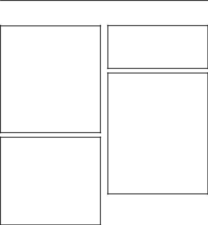
HARDWARE USED
Mounting Screw
Hinge Bracket
Anchoring Screws
Door and Latch Screws
25

Installation Instructions
REVERSING THE DOOR SWING (if desired)
BEFORE YOU START |
2 DISASSEMBLE THE DOOR ASSEMBLY |
Unplug the dryer from its electrical outlet. |
Remove 16 door screws and male end of latch |
|
from the inner side of the door. |
1 REMOVE THE DOOR ASSEMBLY
Remove hinge bracket anchoring screws.
Remove the inner face.
Slide door and hinge assembly upward; then remove the assembly from the dryer front panel.
Lift and rotate the window assembly 180º and replace. Also rotate the inner face 180° and replace.
26

Installation Instructions
3 REPLACE DOOR ASSEMBLY
Replace a door screw in the center of the side opposite the hinge. Then put the male end of the latch into place and fasten with two door screws.
Replace all door screws that were removed.
Remove the female end of the latch from the front panel of the dryer, rotate 180° and replace on
the opposite side.
3 REPLACE DOOR ASSEMBLY (CONT.)
Move the mounting screw to the upper screw hole position on the hinge so that the door can be set on the cabinet during final installation.
Fasten the hinge back on at the top and bottom with the hinge mounting screws.
27
Installation Instructions
STACKING THE WASHER AND DRYER (if desired)
If you are planning to stack the washer and dryer, order Stacking Kit number GE24STACK to be used for this dryer. Kit sold separately.
BEFORE YOU BEGIN
Read these instructions completely and carefully.
• IMPORTANT – Save these instructions for local electrical inspector’s use.
• IMPORTANT – Observe all governing codes and ordinances.
•Note to Installer – Be sure to leave these instructions with the Consumer.
•Note to Consumer – Keep these instructions for future reference.
•Service must be performed by a qualified installer.
•Proper installation is the responsibility of the installer.
•Stacking installations may require a power cord up to 6 feet in length.
FOR YOUR SAFETY:
 WARNING –
•Electric Shock Hazard. Disconnect power before installing. Failure to do so could result in serious injury or death.
•Potential Personal Injury. More than two people are recommended to lift the dryer into position because of its weight and size. Failure to do so could result in personal injury or death.
•Avoid Tipping and Rupture of Utility Services. Dryer must be securely attached to the washer. DO NOT place the washer on top of the dryer. Failure to do so could result in personal injury/ death or property damage.
MINIMUM CLEARANCE OTHER THAN ALCOVE OR CLOSET INSTALLATION
Minimum clearance to combustible surfaces
and for air opening are: 0” both sides and 3” front and rear. Consideration must be given to provide adequate clearance for installation and service.
REQUIREMENTS FOR ALCOVE OR CLOSET INSTALLATION
•Your dryer is approved for installation in an alcove or closet, as stated on a label on the dryer back.
•The dryer MUST be vented to the outdoors. See the EXHAUSTING THE DRYER section.
•Minimum clearance between dryer cabinet and adjacent walls or other surfaces is:
0” either side
3” front and rear
•Minimum vertical space from floor to overhead shelves, cabinets, ceilings, etc., is 67.7”.
•Closet doors must be louvered or otherwise ventilated and have at least 60 square inches of open area equally distributed. If the closet contains both a washer and a dryer, doors must
contain a minimum of 120 square inches of open area equally distributed.
NOTE: WHEN THE EXHAUST DUCT IS LOCATED AT THE REAR OF THE DRYER, MINIMUM CLEARANCE FROM THE WALL IS 5.5 INCHES.
28
Installation Instructions
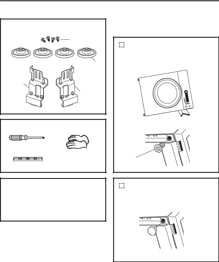
KIT CONTENTS (GE KIT #GE24STACK)
Screws (4) |
Rubber pads (4)
Bracketstack (R)
Bracketstack (L)
TOOLS YOU WILL NEED
Phillips screwdriver
Gloves
Level
INSTALLATION PREPARATION
Remove the packaging.
Flatten the product carton to use as a pad to lay the dryer down on its side. Continue using the carton to protect the finished floor in front of
the installation location.
INSTALLING THE STACK
BRACKET KIT
1REMOVE THE DRYER LEVELING LEGS
A.Carefully lay the dryer on its side. Use the packing material so you don’t scratch the finish on the dryer.
B. Remove the dryer leveling legs.
Unscrew and remove all 4 leveling legs
2INSTALL RUBBER PADS TO DRYER BASE
A.Locate the 4 rubber pads in the parts package. Insert rubber pads into the leveling leg holes.
B. Set the dryer upright.
29
Installation Instructions
STACKING THE WASHER AND DRYER (if desired) (cont.)
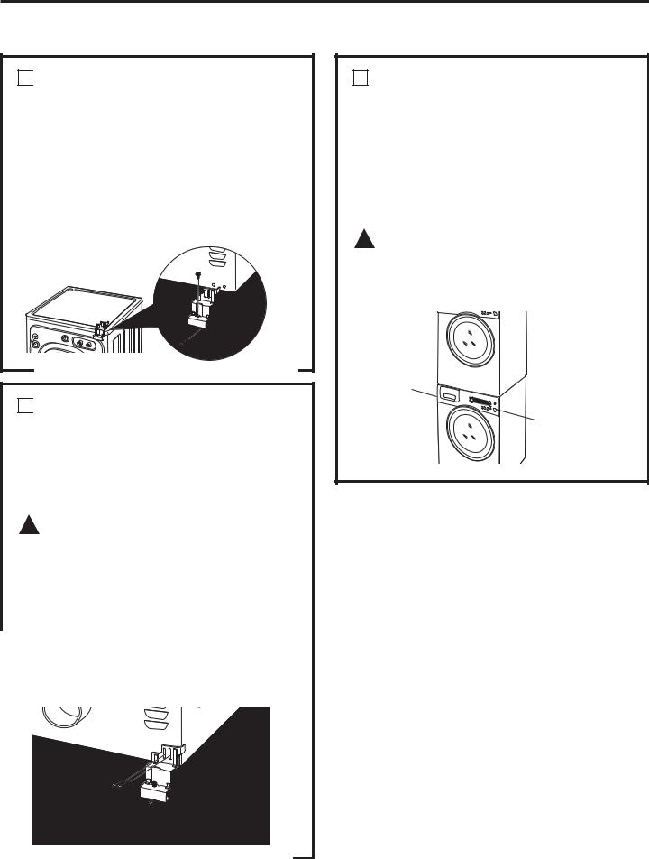
3INSTALL BRACKET TO WASHER
A.Remove washer top cap screw from the rear left. Align left bracket holes with top cap screw hole on rear left of the unit and replace screw. NOTE: Leave screws loose so dryer hole alignment will be easier.
B.Drive next screw through the bracket into the rear of the washer.
C.Repeat the above steps with the right side.
4INSTALL DRYER AND BRACKET ON DRYER
A.Lift the dryer on top of the washer. Protect the washer control panel with cardboard or other protection. Be sure to lift the dryer high enough to clear the washer control panel.
 WARNING – Potential Personal Injury. More than two people are recommended to lift the dryer into position because of its weight and size. Failure to do so could result in personal injury or death.
B.Align the holes in the bracket with the holes in the back of the dryer. Using a Phillips screwdriver, attach the 2 #8 x 1/2” tapping screws.
C.Tighten the dryer bracket screws; then tighten all stacking kit screws.
5FINALIZE THE INSTALLATION
A.Refer to the washer Installation Instructions to complete the washer installation.
B.Refer to the dryer Installation Instructions to complete the dryer installation.
C.Carefully slide or walk the stacked washer and dryer into place. Use felt pads or other sliding device to assist moving and to protect flooring.
 WARNING – Potential Personal Injury. Do not push on the dryer once installed to top of the washer. Pushing on the dryer may result in pinched fingers.
Place hands here
Place
hands here
30
 Loading...