


Gateway G200, G800, G400, G100 User Manual

Gateway Series
G100 / G200 / G400 / G800
Administr ato r Man ual
601-00020 Rev. B

445 Jan Davis Drive
Digium, Inc.
Huntsvil le, AL 35806
United States
Main Number: +1 (256)-428-6000
Tech Support: +1 (256)-428-6161
U.S. Toll Free: +1 (877)-344-4861
Sales: +1 (256)-428-6262
www.digium.com
www.asterisk.org
www.asterisknow.org
© Digium, Inc. 2013
All rights reserved.
No part of this publication may be copied, distributed, transmitted, transcribed, stored in a
retri eval s yst em , o r tran sl at ed int o a ny hu man or co mpu ter l angu ag e wit h ou t the p rio r wr i tte n
permission of Digium, Inc.
Digium, Inc. has made every effort to ensure that the instructions contained in this document
are ade q uate an d err o r free. The m a nu fa ct u rer will, if n ec es s ar y , ex pl ain issu es whic h m ay
not be covered by this documentation. The manufacturer’s liability for any errors in the
docume nts is limi ted to the cor rection of errors and the aforementioned advisory services.
This doc ument h as been p repar ed for us e by profe ssiona l and pr operly tr ained p ersonn el,
and the cus to m er as su m es fu ll re sp onsibi li ty w he n us in g it .
Adobe and Acrobat are registered trademarks, and Acrobat Reader is a trademark of Adobe
Systems Incorporated.
Asterisk, Digium, Switchvox, and AsteriskNOW are registered trademarks and Asterisk
Business Edition, AsteriskGUI, and Asterisk Appliance are trademarks of Digium, Inc.
Any oth er tr a dem ark s m en ti oned i n t he do cu me nt ar e t he pr op ert y of t h ei r r es pe ctiv e ow ner s.
Digium, Inc. Page 2

Compliance Information
Compliance information for this product is available at
http://www.digium.com/compliance.
Digium, Inc. Page 3

Introduction to Gateway Series Documentation
This manual contains product information for the Gateway Series
appliances. Be sure to refer to any supple mentary documents or release
notes that were shipped with your equipment. The manual is organized in
the following manner:
Chapter/
Appendix
1
2
3
4
A
B
C
Overview Identifies the features of your unit.
Unit Installation Provides instructions for installing the unit.
Configuration Provides instructions on how to configure the un it.
Troublesh ooting Explains resolut ions to common problems and
Pin Assignments Describes the states supported by the unit.
Specifications Details unit specifications.
Glossary and
Acronyms
Title Description
frequentl y as ked questions per taining to unit
installation and usage.
Defines terms related to this product.
Digium, Inc. Page 4

Symbol Definitions
Caution stat emen ts in dicate a c onditio n whe r e d amage to t he un it o r
its configuration could occur if operational procedures are not
followed. To reduce the risk of damage or injury, follow all steps or
procedures as instructed.
The ESD sym b o l in d i ca t es electrostat i c s en si ti ve d e vi ces. Obser v e
prec autions for handling devices. Wear a prop er ly grounded
electrostatic discha rge (ESD) wrist strap while handling the device.
The Electrical Hazard Symbol indicates a possibility of electrical
shock when operat ing this unit in certain situations. To reduce the
risk of damage or injury, fol low all steps or proc edures as
instructed.
Digium, Inc. Page 5
Important Safety Instructions
Servicing.
Do not attempt to service this unit. There are no user-serviceable
parts inside. Refer servicing to qualified service personnel.
Batteries.
The batteries in the unit are not user-servic eable. Refer servicing to
qualified service personnel.
CAUTION - Risk of explosion if battery is replaced by an incorrect
type. Batter ies should be disposed of according to the local laws and
regulations of your region.
ATTENT ION - II y a danger d’ex plosion s’il y a remplacement
incorrect de la batterie. Remplacer uniquement avec une batterie du
même type ou d’un type equivalent recommandé par le
constructeur.Mettre au rebut les batteries usages conformément aux
instructions du fabricant.
Water and Moisture.
Do not spill liquids on this unit. Do not operate this equipment in a
wet environmen t.
Heat.
Do not operate or store this product near heat sources such as
radiators, air ducts, areas subject to di rect, intense sunlight, or other
products that produce heat.
Caution.
To reduce the risk of fire, use only No. 26 AWG or larger
telecommunication wiring for network connections.
Static Electricity.
To reduce the risk of damaging the unit or your equipment, do not
attempt to open the e nclosure or gain access to areas w here you are
not instructed to do so. Refer servicing to qualified service personnel.
Save these instructions for future reference.
Digium, Inc. Page 6

TABLE OF CONTENTS
Chapter 1
Overview . . . . . . . . . . . . . . . . . . . . . . . . . . . . . . . . . . . . . . . . . . . . . . .11
Chapter 2
Unit Installation . . . . . . . . . . . . . . . . . . . . . . . . . . . . . . . . . . . . . . . . . .16
Chapter 3
Configuration . . . . . . . . . . . . . . . . . . . . . . . . . . . . . . . . . . . . . . . . . . . .45
Chapter 4
Troubleshooting . . . . . . . . . . . . . . . . . . . . . . . . . . . . . . . . . . . . . . . . .77
Echo-Cancellation . . . . . . . . . . . . . . . . . . . . . . . . . . . . . . . . . . . . . .15
Unpacking the Unit . . . . . . . . . . . . . . . . . . . . . . . . . . . . . . . . . . . . .17
Shipment Inspection . . . . . . . . . . . . . . . . . . . . . . . . . . . . . . . . . . . .18
Front Panel Identification . . . . . . . . . . . . . . . . . . . . . . . . . . . . . . . .19
Unit Identification . . . . . . . . . . . . . . . . . . . . . . . . . . . . . . . . . . . . . .23
Hardware Installation . . . . . . . . . . . . . . . . . . . . . . . . . . . . . . . . . . . 24
Connecting to the Gateway S eries . . . . . . . . . . . . . . . . . . . . . . . . .33
Settings and Configuration . . . . . . . . . . . . . . . . . . . . . . . . . . . . . . .49
Logging and Reporting . . . . . . . . . . . . . . . . . . . . . . . . . . . . . . . . . .65
Status and Diagnostics . . . . . . . . . . . . . . . . . . . . . . . . . . . . . . . . . .66
Maintenance . . . . . . . . . . . . . . . . . . . . . . . . . . . . . . . . . . . . . . . . . .72
Frequently Asked Questions . . . . . . . . . . . . . . . . . . . . . . . . . . . . . .80
Free Installation Support . . . . . . . . . . . . . . . . . . . . . . . . . . . . . . . . .84
Digiu m, In c . Page 7

Table Of Contents
Appendix A
Pin Assignments . . . . . . . . . . . . . . . . . . . . . . . . . . . . . . . . . . . . . . . . .85
Appendix B
Specifications . . . . . . . . . . . . . . . . . . . . . . . . . . . . . . . . . . . . . . . . . . .8 7
Appendix C
Glossary and Ac ronyms . . . . . . . . . . . . . . . . . . . . . . . . . . . . . . . . . . .8 9
Digium, Inc. Page 8

List of Figures
Figure 1: TDM PBX to VoIP Scenario . . . . . . . . . . . . . . . . . . .13
Figure 2: VoIP PBX to TDM Scenario . . . . . . . . . . . . . . . . . . .13
Figure 3 : TDM PBX to TDM and VoIP Scena rio . . . . . . . . . . .14
Figure 4: G100 Single Port Appliance . . . . . . . . . . . . . . . . . . .19
Figure 5: G200 Dual Port Appliance . . . . . . . . . . . . . . . . . . . . 20
Figure 6: G800 Octal Port Appliance . . . . . . . . . . . . . . . . . . . .21
Figure 7 : Side-by-side Rack Mounting . . . . . . . . . . . . . . . . . . .29
Figure 8: Acceptable Wall Mount Orientation . . . . . . . . . . . . .30
Figure 9: IP Configuration Menu for G100 / G200 . . . . . . . . . .36
Figure 10: IP Configuration Menu fo r G400 / G800 . . . . . . . . . .40
Figure 1 1: Login Screen . . . . . . . . . . . . . . . . . . . . . . . . . . . . . . .46
Figure 12: Main Menu . . . . . . . . . . . . . . . . . . . . . . . . . . . . . . . .48
Digium, Inc. Page 9

List of T able s
Table 1: Gateway Series Models. . . . . . . . . . . . . . . . . . . . . . 23
Table A-1: Gigabit Ethernet Port Pinouts . . . . . . . . . . . . . . . . . .85
Table A-2: RJ45 T1/E1 Port Connector . . . . . . . . . . . . . . . . . . . . 86
Digium, Inc. Page 10

Chapter 1 Overview
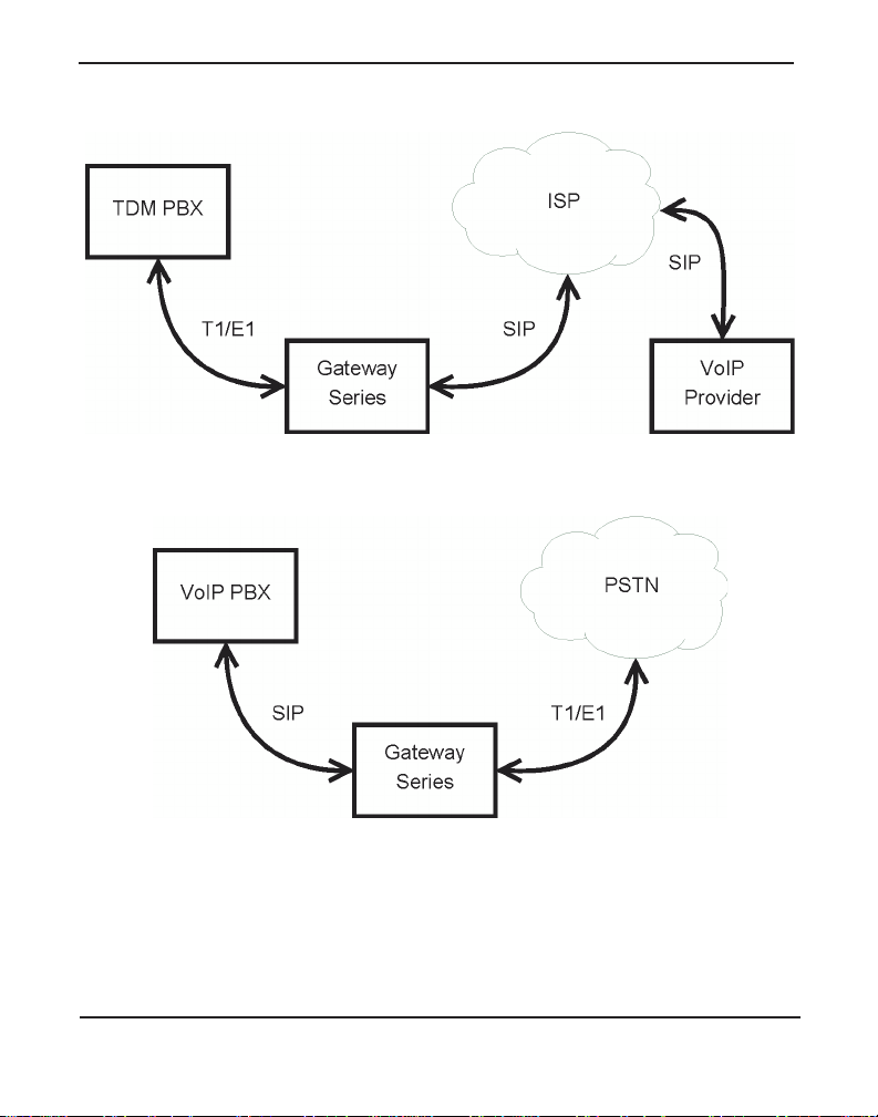
Digium's Gateway Series is a converged media gateway product line
designed to interface between TDM (T1/E1) and IP networks (SIP). The
Gateway Series connects lega cy tele phone systems to IP networks and
seamlessly integr ates VoIP PBXs with the PSTN. Powered by innovative
hardware and software solut ions, Digium’s Gateway Series are managed
by a simple, intuitive web-based interface.
Digiu m, In c . P age 1 1

Supported V oice Modes:
Chapter 1: Overview
PRI CPE and PRI NET (T1 / E1)
– National ISDN 1 / NI1
– National ISDN 2 / NI2
– EuroISDN
– 4ESS (AT&T)
– 5ESS (Lucent)
– DMS100
– Q.SIG
E&M (T1 only)
– Wink
– Feature Group B
– Feature Group D
FXO and FXS (T1 only)
– Ground Start
– Loop Start
– Loop Start with Disconnect Detect (Kewls ta rt)
SIP
Example scenarios utiliz ing the Gateway Series are i llustrated in Figur e 1,
Figure 2, and Figure 3.
Digium, Inc. Page 12
Chapter 1: Overview
Figure 1: TDM PBX to VoIP Scenario
Figure 2: V oIP PBX to TDM Sc en ario
Digium, Inc. Page 13

Chapter 1: Overview
Figure 3: TDM PBX to TDM and VoIP Scenario
Digium, Inc. Page 14

Echo-Cancellation
Chapter 1: Overview
Administrators connecting their Gateway Series appliances to the PSTN
or other devices are likely to be placing calls that will result, at some
point, in an unbalanced 4-wire/2-wire hybrid. The result of this hybrid is
the reflection of a near-end echo to the calling party. Elimination of this
echo is the responsibility of echo cancellation.
The Gateway Series appliance utilizes hardware-based voice processors
for echo cancellation an d codec tra nscoding. Its hardware echo canceller
is designed to handl e up to 128m s of e cho cancel lation ac ross a ll channe ls
and provides a G.168 compliant echo cancellation solution.
If not explicitly disable d in the Gateway Series web GUI, the hardwarebased echo canceller will automatically operate and cancel all network
echo within its tail range (1024 taps).
Digium, Inc. Page 15

Chapter 2 Unit Installation
This chapter provides the following information:
Unpacking the Unit on page 17
Sh i pment Inspecti o n on page 18
Front Panel Identification on page 19
U nit I den ti fica ti on on page 23
Hardware Installation on page 24
Note: The Gateway Series applia nce installation instruct ions are
written so that they will apply to any model in the series. Examples
and model specific information are included as needed.
Digiu m, In c . Page 16

Unpacking the Unit
Chapter 2: Unit Installation
When you unpack your unit, carefully inspect it for any damage that m ay
have occurred in shipment. If damage is sus pected, file a claim with the
carrier and contact the reseller from which the unit was purchased. If the
unit was purchased direct ly from Digium, contact Digium Technical
Support at +1 (256)-428-6161. Keep the original shipping container to
use for future shipment or proof of damage during shipment.
Note: Only qualified service personnel should install t he unit. Users
should not attempt to perform thi s function themselves. The installer
must ensure that the equipment is reliably earth grounded in
accordance with the National Electrical Code.
Digium, Inc. Page 17

Chapter 2: Unit Installation
Shipment Inspection
The following items are includ ed in shipment of a Gateway Series
appliance:
Gateway Series appliance
Power cord with attached T1/E1 loopback plug
M ounting brackets (2 each)
Bracket mounting screws, #8-32 black truss head, Philli ps, 3/16”
Side-by-side mounting screws, #6-32 pan head, Phillips, 3/16” length
length (6 each)
(3 each)
Side-by-side mounting shoulder washers (3 each)
Rubber feet (4 each)
Ground nut
Double-crimp ground ring terminal
Quickstart Guide
Note: After inspecting the shipment, Digium requires that the
appliance be registere d for support eligibi lit y. Unregister ed appliances
are not eligible for Digium suppo rt. Please refer to Free Installation
Support on page 84 for additional information on how to obtain
assistance from Digium Technical Support.
Digium, Inc. Page 18

Chapter 2: Unit Installation
USB
Recovery
T1/E1
Gigabit
Status
Ethernet
Device
Status
Ethernet
Status
T1/E1
Port
Front Panel Identification
This section describes the components on the front panel of the Gateway
Series models.
Figure 4: G100 Single Port Appliance
Digium, Inc. Page 19

Chapter 2: Unit Installation
USB
Recovery
T1/E1
Gigabit
Status
Ethernet
Device
Status
Ethernet
T1/E1
Status
Port
Figure 5: G200 Dual Port Appliance
Digium, Inc. Page 20

Chapter 2: Unit Installation
USB
Recovery
T1/E1
Gigabit
Status
Reset
Ethernet
Device
Status
Ethernet
T1/E1
Status
Port
Figure 6: G800 Octal Port Appliance
Device Status - This LED corresponds to the status of the Gateway
Series appliance. See Frequently Asked Questions on page 80 for
more information.
Gigabit Ethernet - The 10/100/1000BaseT Ethernet port(s) provides
the ability to connect to an int erna l or external network using an RJ45
interface and support s Auto-MDIX. It is used to pass Ethernet packetized voice and web management data between the Gateway Series
and the network. See Gigabit Ethernet Port Pinouts on page 85 for
more information.
Second Gigabit Ethernet (G400/G800 only) - The second 10/100/
1000BaseT Ethernet port(s) provides the ability to connect to an internal or external network using an RJ45 interface and supports AutoMDIX. It is used to pass Ethernet packetized voice and web management data betwe en the Gateway Series and the network. See Gigabit
Ethernet Port Pinouts on page 85 for more information.
Digium, Inc. Page 21

Chapter 2: Unit Installation
Ethernet Stat us - The se LEDs correspond to the status of the Ethernet
connection. See Frequently Asked Questions on page 80 for more
information.
USB Recovery - This port can be used to perform a firmware recovery
and configuration reset. See Fi rmwar e Recovery and Configurat ion
Reset on page 78 for more information.
Warning! The USB Recovery port provides a limited amount of
current which is suf ficient only to power a USB flash drive. Do not
connect any other type of device to this port. The USB flash drive
should be fully USB 2.0 compliant.
T1 /E 1 Po rt(s) - These ports are used for connecting T1 or E1 cables.
See RJ45 T1/E1 Port Connector on page 86 for more informat io n.
T1 /E1 Status - These LEDs corr es po nd to the st at us of the T 1/E1
ports. See Frequently Asked Questions on page 80 for more infor-
mation.
Reset Switch (G400/G800 only) - This recessed switch is used to
restart the Gateway Serie s appliance or reset its GUI password. See
Frequently Asked Questions on page 80 for more information.
Digium, Inc. Page 22

Chapter 2: Unit Installation
Unit Identification
The defining character istic of the Gateway Series models are the number
of T1/E1 and Ethernet ports supporte d. S ee Table 1 for a list of the
various models.
Table 1: Gateway Series Models
Model Type T1/E1 Ports Ethernet Ports
G100 T1/E1 1 1
G200 T1/E1 2 1
G400 T1/E1 4 2
G800 T1/E1 8 2
Digium, Inc. Page 23

Hardware Installat ion
Chapter 2: Unit Installation
This sectio n describes how to properly inst all the hardware for a Gateway
Series appliance.
Caution
Only qualified service personnel should continue with
hardware installation and configuration of the Gateway Series
appliance. Users should not attempt to perform these functions
themselves.
Caution
This equ ipmen t is i nt e n d e d fo r u s e in Restricted Ac ce s s A reas
only where equipotential bonding has been applied.
Grounding
The Gateway Series appliance must be proper ly earth gr ounded for safety
reasons. If the unit is not properly earth grounded, the unit and/or other
equipment connected to the unit could be damaged. If a Gateway Series
appliance is damaged while it is imprope rly grounded, the warranty on
the Gateway Series appliance is void.
A ground lug is located on the opposite side from the front panel of a
Gateway Series a pplian ce. Atta ch an a ppropr iate l eng th and gauge of wire
to the double-crimp ground ring terminal. The wire length should be as
short as possible, and gauge should be 18 AWG or greater. Stra nded or
solid wire is acceptable . Wire is not provided with the Gateway Series
Digium, Inc. Page 24

Chapter 2: Unit Installation
appliance. Double crimp the ground ring terminal to the wire. Next, slide
the ground ring terminal over the ground lug. Then fasten the ground ring
terminal to the ground lug using the gro und nut. The ground nut must be
turned clockwis e to tigh ten it o nto th e groun d lug. The opposite end of the
wire that is connected to the ground ring terminal should be securily
fastened to an unpainted metalic section of a properly earth grounded
equipment rack. A connector for the opposite end of the wire is not
provided with the Gateway Series appliance.
Note: Taking into considera tion the requirements of all equipment
connected to or sharing the rack, the equipment rack should be
properly earth grounde d. Ref er to the manu facturer of the rack for
instructions on how to properly e arth ground the rack.
Important
Use only a grounded electrical outlet when connecting the
Gateway Series appliance to a power sour ce. If you do not
know whether the outlet is grounded, consult wi th a qualified
electrician.
Digium, Inc. Page 25

Chapter 2: Unit Installation
Mounting
The included hardware allows the Gate way Serie s appliance to be wall
mounted, rack mounted side-by-side with another Gateway Series
appliance, or placed flat on a leve l surface. If a single Gateway Series
appliance is to be rack mounted, the optional long mounting bracket (not
supplied, part number 3244-00042) must be used. The optional long
mounting bracket can be ordered by contacting a Digium reseller or
Digium directly.
Important
Reliable ear th grounding of ra ck-mount equipment should be
maintained. Particular atte ntion should be given to provide
connection other than direct connections to the branch circuit
(e.g., use of power strips).
Important
Mounting of the Gateway Series appliance in a rack should be
such that no hazardous condition is achieved due to uneven
mechanical loading. Do not place heavy obje cts on top of the
unit, or pull down on the mounted unit. Consider the
mechanical l oadi ng of ex terna l cable s. The wei ght of th e cable s
can pull on the unit and create unev en loading. Secure heavy
cables with external cable trays.
Important
If rack mounting, ins tall the Gateway Ser ies appliance in a rack
so that the amount of airflow r equired for safe operation is not
compromised.
Digium, Inc. Page 26

Chapter 2: Unit Installation
Important
If the Gateway Series appliance is installed in a system that is
in turn installed in a closed or mu lti-unit rack ass embly, the
operating ambient temperature of the rack environment may be
signific antly greater t han the room ambient. Whi le the
maximum safe operat ing temperature is 50°C, consideration
should be given to ins talling the unit in an environment
compatible with the maximum recommended ambient
temperature of 45°C for long ter m reliabili ty and maximum
performance.
Single Unit Rack Mount:
In order to rack mount the Gateway Series appliance by itself, place one
of the short mounting brackets on the front of one side of the Gateway
Series appliance. Line up the hole s from the mounting bracket to the
threaded holes on the front sid e of the Gateway Ser ies appliance. Two #8
black truss head sc rews should be inserted and tur ned clockwise to fasten
the mounting bracket. Do not over-tighten. Repeat these steps when
installing the optional long mounting bracket (not supplied, part number
3244-00042) on the othe r side of the Gateway Series appl iance. Then use
another 2 #8 black truss head screws on each mounting bracket to secure
the Gateway S eries ap pl ian ce to a rack .
Digium, Inc. Page 27

Chapter 2: Unit Installation
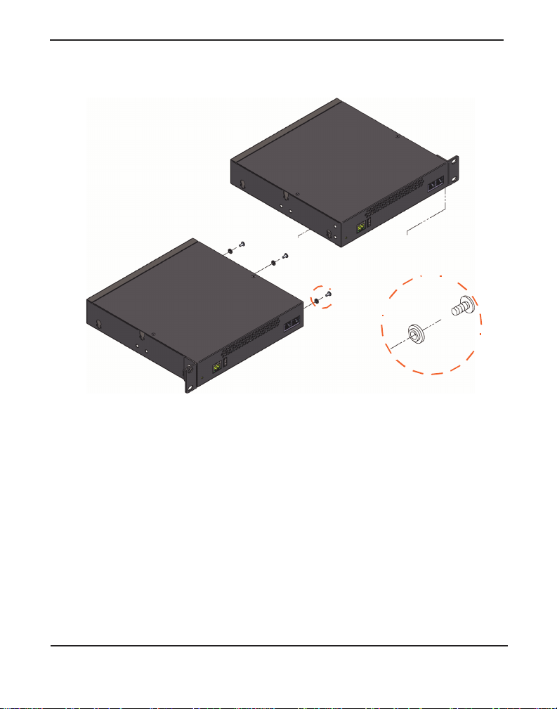
Side-by-s ide Rack Mount:
In order to rack mount the Gateway Series appliance side-by-side with
another Gateway Series appliance, place one of the short mounting
brackets on the front of the le ft side of the first Gateway Serie s appliance.
Line up the holes from the mounting bracket to the threaded holes on the
front of the left side of the first Gateway Series appliance. Two #8 black
truss head screws should be inserted and turned clockwise to fasten the
mounting bracket. Repeat these steps when installing a short mounting
bracket on the front of the right sid e of the seco nd Gateway Series
appliance.
Each of the three #6 pan head screws should be inserted into a shoulder
washer as shown in Figur e 7 on page 29. Make sur e the narr ow side of the
shoulder washer is away from the head of the screw. The three screws
should then be insert ed and turned clockwise to fasten to th e si de-by-side
holes on the right side of the first Gate way Serie s appliance. Do not
overtighten the screws or th e shoulder washers could be damaged.
Connect the first and second Gatewa y Series appliances together by
putting the heads of three screws & shoulder washers into the thre e keyed
insets. Then push down on th e second Gateway Ser ies applia nce a s sh own
in Figure 7. Make sure the units a re flat against each other before pushing
the second unit down. Otherwise the shoulder washers may be damaged.
Use two truss head screws (not supplied) on each mounting bracket to
secure both Gateway Series appl iances to a rack.
Digium, Inc. Page 28
Chapter 2: Unit Installation
Figure 7: Side-by-side Rack Mounting
Wall M ount :
In order to wall mount the Gateway Series appliance, the short mounting
brackets should be flipped an d rotate d, a nd fastened on the middle of the
right and left sides of the Gateway Series appliance as shown in Figure 8
on page 30. The unit should be mounted at or below eye level to pr operly
view the LEDs. In addition, the Gateway Series appli ance s hould be
properly oriented as shown in Figu re 8. Ori entations other than what is
shown in Figu re 8 are not acce p ta ble .
Digium, Inc. Page 29

Chapter 2: Unit Installation
Right side down
Front side
Back side
Left side
Right side
If the Gateway Series applian ce is pla ced in the “right side down”
orientation, the 2 remaining #8 black truss head mounting screws should
be fully inser ted into the screw hole s near the front of the right side of the
Gateway Series applianc e. In ad dition, the three #6 pan head screws
should be ful ly inserted into the side-by-side holes on the right sid e of the
first Gateway Series appl iance.
Note: The Gateway Series appliance must be properly grounded for
safety reaso ns. I f the uni t i s not prope rly groun ded, d amage coul d a rise
to the unit and/or other equipment connected to the unit.
Figure 8: Acceptable Wall Mount Orientation
Digium, Inc. Page 30
 Loading...