

Page 1

Gateway 840 VT-100
User's Guide
Installing
Getting Help
Page 2

Contents
1 Introduction. . . . . . . . . . . . . . . . . . . . . . . . . . . . . . . . . . . . . . . . . . . . . . . . . . . . . . 1
Features . . . . . . . . . . . . . . . . . . . . . . . . . . . . . . . . . . . . . . . . . . . . . . . . . . . . . . . . . . . 2
Troubleshooting assistance . . . . . . . . . . . . . . . . . . . . . . . . . . . . . . . . . . . . . . . . . . . . 3
2 Accessing the Configuration Utility . . . . . . . . . . . . . . . . . . . . . . . . . . . . . . 5
Accessing the utility . . . . . . . . . . . . . . . . . . . . . . . . . . . . . . . . . . . . . . . . . . . . . . . . . . 6
Using the VT-100 terminal . . . . . . . . . . . . . . . . . . . . . . . . . . . . . . . . . . . . . . . . . . . . 7
Navigating the SATA RAID configuration utility . . . . . . . . . . . . . . . . . . . . . . . . . . . . 9
Menu system . . . . . . . . . . . . . . . . . . . . . . . . . . . . . . . . . . . . . . . . . . . . . . . . . . . 10
Viewing controller information . . . . . . . . . . . . . . . . . . . . . . . . . . . . . . . . . . . . . . . . . 13
3 Creating Disk Arrays. . . . . . . . . . . . . . . . . . . . . . . . . . . . . . . . . . . . . . . . . . . . 17
Overview . . . . . . . . . . . . . . . . . . . . . . . . . . . . . . . . . . . . . . . . . . . . . . . . . . . . . . . . . 18
Understanding arrays . . . . . . . . . . . . . . . . . . . . . . . . . . . . . . . . . . . . . . . . . . . . . . . 19
Terminology . . . . . . . . . . . . . . . . . . . . . . . . . . . . . . . . . . . . . . . . . . . . . . . . . . . . 19
Optimization and drive selection for RAID 5 arrays . . . . . . . . . . . . . . . . . . . . . 21
Creating arrays . . . . . . . . . . . . . . . . . . . . . . . . . . . . . . . . . . . . . . . . . . . . . . . . . . . . 22
Configuring array read-ahead and writeback cache . . . . . . . . . . . . . . . . . . . . . . . . 36
Read-ahead cache . . . . . . . . . . . . . . . . . . . . . . . . . . . . . . . . . . . . . . . . . . . . . . 36
Writeback cache . . . . . . . . . . . . . . . . . . . . . . . . . . . . . . . . . . . . . . . . . . . . . . . . 40
Assigning hot spare drives . . . . . . . . . . . . . . . . . . . . . . . . . . . . . . . . . . . . . . . . . . . 47
Deleting an array . . . . . . . . . . . . . . . . . . . . . . . . . . . . . . . . . . . . . . . . . . . . . . . . . . . 50
Expanding an array . . . . . . . . . . . . . . . . . . . . . . . . . . . . . . . . . . . . . . . . . . . . . . . . . 53
Adding additional drives . . . . . . . . . . . . . . . . . . . . . . . . . . . . . . . . . . . . . . . . . . 54
Adding additional sub-arrays . . . . . . . . . . . . . . . . . . . . . . . . . . . . . . . . . . . . . . 57
Trusting an array . . . . . . . . . . . . . . . . . . . . . . . . . . . . . . . . . . . . . . . . . . . . . . . . . . . 61
4 Logical Drives . . . . . . . . . . . . . . . . . . . . . . . . . . . . . . . . . . . . . . . . . . . . . . . . . . 63
Overview . . . . . . . . . . . . . . . . . . . . . . . . . . . . . . . . . . . . . . . . . . . . . . . . . . . . . . . . . 64
Terminology . . . . . . . . . . . . . . . . . . . . . . . . . . . . . . . . . . . . . . . . . . . . . . . . . . . . 64
Accessing the LUN configuration menu . . . . . . . . . . . . . . . . . . . . . . . . . . . . . . . . . 66
Viewing unassigned free space . . . . . . . . . . . . . . . . . . . . . . . . . . . . . . . . . . . . . . . 68
Creating a logical drive . . . . . . . . . . . . . . . . . . . . . . . . . . . . . . . . . . . . . . . . . . . . . . 71
Expanding a logical drive . . . . . . . . . . . . . . . . . . . . . . . . . . . . . . . . . . . . . . . . . 75
Setting logical drive availability . . . . . . . . . . . . . . . . . . . . . . . . . . . . . . . . . . . . . 79
Deleteing a logical drive . . . . . . . . . . . . . . . . . . . . . . . . . . . . . . . . . . . . . . . . . . 82
Modifying a mapped LUN . . . . . . . . . . . . . . . . . . . . . . . . . . . . . . . . . . . . . . . . . 85
i
Page 3

5 SAN LUN Mapping
Overview . . . . . . . . . . . . . . . . . . . . . . . . . . . . . . . . . . . . . . . . . . . . . . . . . . . . . . . . . .90
Terminology . . . . . . . . . . . . . . . . . . . . . . . . . . . . . . . . . . . . . . . . . . . . . . . . . . . . 90
Accessing the SAN LUN mapping configuration menu . . . . . . . . . . . . . . . . . . . . . .91
Viewing SAN LUN mappings . . . . . . . . . . . . . . . . . . . . . . . . . . . . . . . . . . . . . . . . . .93
Creating a SAN LUN mapping . . . . . . . . . . . . . . . . . . . . . . . . . . . . . . . . . . . . . . . . .96
Deleting a SAN LUN mapping . . . . . . . . . . . . . . . . . . . . . . . . . . . . . . . . . . . . . . . .100
Modifying SAN LUN Mapping . . . . . . . . . . . . . . . . . . . . . . . . . . . . . . . . . . . . . . . . .103
Viewing connected hosts . . . . . . . . . . . . . . . . . . . . . . . . . . . . . . . . . . . . . . . . . . . .108
. . . . . . . . . . . . . . . . . . . . . . . . . . . . . . . . . . . . . . . . . . . . . . .89
6 Advanced Configuration and Management . . . . . . . . . . . . . . . . . . . . .111
Setting rebuild parameters . . . . . . . . . . . . . . . . . . . . . . . . . . . . . . . . . . . . . . . . . . .112
Enabling/disabling auto rebuild . . . . . . . . . . . . . . . . . . . . . . . . . . . . . . . . . . . .112
Configuring auto hot spare . . . . . . . . . . . . . . . . . . . . . . . . . . . . . . . . . . . . . . .115
Configuring hot spares . . . . . . . . . . . . . . . . . . . . . . . . . . . . . . . . . . . . . . . . . . . . . .118
Viewing the list of hot spare drives . . . . . . . . . . . . . . . . . . . . . . . . . . . . . . . . .118
Adding or removing hot spare drives . . . . . . . . . . . . . . . . . . . . . . . . . . . . . . . .121
Configuring the hardware . . . . . . . . . . . . . . . . . . . . . . . . . . . . . . . . . . . . . . . . . . . .124
Setting the controller LUN . . . . . . . . . . . . . . . . . . . . . . . . . . . . . . . . . . . . . . . . 124
Setting the controller port ID . . . . . . . . . . . . . . . . . . . . . . . . . . . . . . . . . . . . . .127
Controller port data rate . . . . . . . . . . . . . . . . . . . . . . . . . . . . . . . . . . . . . . . . . .130
Setting the RS-232 configuration . . . . . . . . . . . . . . . . . . . . . . . . . . . . . . . . . . .133
Packetized data transfers/QAS . . . . . . . . . . . . . . . . . . . . . . . . . . . . . . . . . . . .136
Viewing controller information . . . . . . . . . . . . . . . . . . . . . . . . . . . . . . . . . . . . . . . .138
Clearing the configuration . . . . . . . . . . . . . . . . . . . . . . . . . . . . . . . . . . . . . . . . . . . .140
7 Additional Configuration . . . . . . . . . . . . . . . . . . . . . . . . . . . . . . . . . . . . . . .143
Modifying the configuration name . . . . . . . . . . . . . . . . . . . . . . . . . . . . . . . . . . . . .144
Verifying background media . . . . . . . . . . . . . . . . . . . . . . . . . . . . . . . . . . . . . . . . . .147
Including enclosure events in event logs . . . . . . . . . . . . . . . . . . . . . . . . . . . . . . . .150
8 Statistics . . . . . . . . . . . . . . . . . . . . . . . . . . . . . . . . . . . . . . . . . . . . . . . . . . . . . . .153
Overview . . . . . . . . . . . . . . . . . . . . . . . . . . . . . . . . . . . . . . . . . . . . . . . . . . . . . . . . .154
Viewing all statistics . . . . . . . . . . . . . . . . . . . . . . . . . . . . . . . . . . . . . . . . . . . . . . . .155
Dumping data to a text file . . . . . . . . . . . . . . . . . . . . . . . . . . . . . . . . . . . . . . . .157
Viewing access statistics . . . . . . . . . . . . . . . . . . . . . . . . . . . . . . . . . . . . . . . . . . . .158
Viewing readahead statistics . . . . . . . . . . . . . . . . . . . . . . . . . . . . . . . . . . . . . . . . .161
Viewing command cluster statistics . . . . . . . . . . . . . . . . . . . . . . . . . . . . . . . . . . . .163
Viewing miscellaneous statistics . . . . . . . . . . . . . . . . . . . . . . . . . . . . . . . . . . . . . .165
Viewing access statistics on each logical drive . . . . . . . . . . . . . . . . . . . . . . . . . . . 166
Clearing access statistics on each logical drive (LUN) . . . . . . . . . . . . . . . . . . . . .170
Clearing all statistics . . . . . . . . . . . . . . . . . . . . . . . . . . . . . . . . . . . . . . . . . . . . . . . .170
ii
Page 4

9 Event Logs. . . . . . . . . . . . . . . . . . . . . . . . . . . . . . . . . . . . . . . . . . . . . . . . . . . . . 173
Accessing event logs . . . . . . . . . . . . . . . . . . . . . . . . . . . . . . . . . . . . . . . . . . . . . . . 174
Controller events . . . . . . . . . . . . . . . . . . . . . . . . . . . . . . . . . . . . . . . . . . . . . . . . . . 178
Drive events . . . . . . . . . . . . . . . . . . . . . . . . . . . . . . . . . . . . . . . . . . . . . . . . . . . . . . 184
Controller drive port (host) events . . . . . . . . . . . . . . . . . . . . . . . . . . . . . . . . . . . . 190
Enclosure events . . . . . . . . . . . . . . . . . . . . . . . . . . . . . . . . . . . . . . . . . . . . . . . . . . 192
Failed drives . . . . . . . . . . . . . . . . . . . . . . . . . . . . . . . . . . . . . . . . . . . . . . . . . . . . . 195
Clearing event logs . . . . . . . . . . . . . . . . . . . . . . . . . . . . . . . . . . . . . . . . . . . . . . . . 196
10 Diagnostics . . . . . . . . . . . . . . . . . . . . . . . . . . . . . . . . . . . . . . . . . . . . . . . . . . . . 199
Accessing diagnostics . . . . . . . . . . . . . . . . . . . . . . . . . . . . . . . . . . . . . . . . . . . . . . 200
Using offline diagnostics . . . . . . . . . . . . . . . . . . . . . . . . . . . . . . . . . . . . . . . . . . . . 202
Using online diagnostics . . . . . . . . . . . . . . . . . . . . . . . . . . . . . . . . . . . . . . . . . . . . 205
Controller maintenance - downloading firmware . . . . . . . . . . . . . . . . . . . . . . . . . 207
Drive maintenance . . . . . . . . . . . . . . . . . . . . . . . . . . . . . . . . . . . . . . . . . . . . . . . . . 211
Download the firmware from the host . . . . . . . . . . . . . . . . . . . . . . . . . . . . . . 212
Checking RAID 5/50 parity . . . . . . . . . . . . . . . . . . . . . . . . . . . . . . . . . . . . . . . 217
Tracing commands . . . . . . . . . . . . . . . . . . . . . . . . . . . . . . . . . . . . . . . . . . . . . 220
Shutting down the controller . . . . . . . . . . . . . . . . . . . . . . . . . . . . . . . . . . . . . . . . . 223
Dumping diagnostics . . . . . . . . . . . . . . . . . . . . . . . . . . . . . . . . . . . . . . . . . . . . . . . 225
11 Optimizing RAID 5 Write Performance . . . . . . . . . . . . . . . . . . . . . . . . . 227
Introduction . . . . . . . . . . . . . . . . . . . . . . . . . . . . . . . . . . . . . . . . . . . . . . . . . . . . . . 228
Sequential access . . . . . . . . . . . . . . . . . . . . . . . . . . . . . . . . . . . . . . . . . . . . . . 229
Number of outstanding commands . . . . . . . . . . . . . . . . . . . . . . . . . . . . . . . . . 229
Access size . . . . . . . . . . . . . . . . . . . . . . . . . . . . . . . . . . . . . . . . . . . . . . . . . . . 229
Access alignment . . . . . . . . . . . . . . . . . . . . . . . . . . . . . . . . . . . . . . . . . . . . . . 229
Using RAID 5 sub-arrays . . . . . . . . . . . . . . . . . . . . . . . . . . . . . . . . . . . . . . . . . . . 230
Experiencing multiple drive failures . . . . . . . . . . . . . . . . . . . . . . . . . . . . . . . . 231
Promoting faster rebuild . . . . . . . . . . . . . . . . . . . . . . . . . . . . . . . . . . . . . . . . . 231
Summary . . . . . . . . . . . . . . . . . . . . . . . . . . . . . . . . . . . . . . . . . . . . . . . . . . . . . . . . 232
A Technical Support . . . . . . . . . . . . . . . . . . . . . . . . . . . . . . . . . . . . . . . . . . . . . 233
Technical Support . . . . . . . . . . . . . . . . . . . . . . . . . . . . . . . . . . . . . . . . . . . . . . . . . 234
Telephone numbers . . . . . . . . . . . . . . . . . . . . . . . . . . . . . . . . . . . . . . . . . . . . 234
Notices . . . . . . . . . . . . . . . . . . . . . . . . . . . . . . . . . . . . . . . . . . . . . . . . . . . . . . . . . . 235
Index . . . . . . . . . . . . . . . . . . . . . . . . . . . . . . . . . . . . . . . . . . . . . . . . . . . . . . . . . . . . . . 237
iii
Page 5

iv
Page 6

Introduction
This guide provides the operational and reference
information to configure and manage the RAID controllers
installed in your Gateway 840 Series storage system. The
controllers are accessed through a VT-100 terminal using a
menu-based user interface, connected directly to the RAID
controllers.
This guide contains step-by-step procedures to access the
VT-100 terminal utility, as well as perform configuration
functions and enclosure monitoring.
1
1
Page 7

Chapter 1: Introduction
Features
Your Gateway 840 has a menu-based software utility designed to configure and
manage the RAID controller in your new storage enclosure. It provides
centralized management to control primary storage assets vital to ensuring
maximum data reliability, network up-time, and system serviceability. It lets
you manage the storage system by accessing the configuration utility locally.
This software guide provides the operational and reference information to
configure and manage the SATA RAID controller installed in your Gateway 840,
using this menu-based user interface.
The following are some of the major features of local RAID configuration utility.
■ Simple, straight-forward user interface
■ Menu-based interface that works with a wide range of operating systems
■ Easy access and navigation
■ Host LUN and LUN mapping configuration
■ A comprehensive, non-volatile event log
■ Useful offline or online diagnostics
2
www.gateway.com
Page 8

Troubleshooting assistance
Troubleshooting assistance
To help troubleshoot problems with your system, the Event Logs chapter, as
well as on-line help, provides a list of all the events that can occur, along with
a suggested cause and action to take. When a warning or error event occurs,
you can review the event log, locate the suspect event, and see “Event Logs”
on page 173 or help section to determine the possible cause or causes and the
suggested action to take. Also see “Diagnostics” on page 199.
www.gateway.com
3
Page 9

Chapter 1: Introduction
4
www.gateway.com
Page 10

Accessing the
Configuration
Utility
This chapter provides information on accessing the
configuration utility. Read this chapter to learn how to:
■ Access the utility
■ Use the VT-100 terminal
■ Navigate the configuration utility
■ View controller information
2
5
Page 11

Chapter 2: Accessing the Configuration Utility
Accessing the utility
You can access the SATA RAID controller by using a VT-100 terminal connected
to the RS-232 serial ports on the controller’s rear panel. Configure your terminal
using the procedures described in “Using the VT-100 terminal” on page 7.
Important You can also choose to use StorView Storage
Management software to manage and monitor the
enclosure and SATA RAID Controller. Refer to the
840 SATA RAID StorView User’s Guide
information.
Gateway
for more
6
www.gateway.com
Page 12

Using the VT-100 terminal
Using the VT-100 terminal
Access to the RAID controller is accomplished by using its onboard
configuration utility with a VT-100 terminal or terminal emulation connected
to the RS-232 serial port on the controller.
A SATA communication RS-232 cable (provided with the hardware) is used to
connect the terminal to the serial port on the SATA RAID controller.
Configure your host system or terminal RS-232 port to use the following
settings:
Setting Value
Terminal Emulation ANSI
Function Terminal Keys
Fonts Terminal
Translations None
Columns 80
Set the communications parameters for the terminal program as follows:
Setting Value
Baud Rate 115,200
Data Bits 8
Stop Bits 1
Parity None
Flow Control None
Connector COM1 (typically)
To access the RAID controllers:
1 Connect the host terminal to the serial port on the controller using a
null-modem serial cable (use the configuration information in the
preceding tables).
2 Turn on the terminal and the Gateway 840 Series storage system.
www.gateway.com
7
Page 13

Chapter 2: Accessing the Configuration Utility
3 From the computer or terminal connected to the RAID controller, start your
terminal emulation software.
Important Make sure that your terminal emulation software is set to
use the correct COM port on your computer.
4 From the terminal window, press CTRL + W. The Main Menu opens.
You can now perform all of the functions described in the following chapters.
All steps begin from the Main Menu.
If an event or error occurs, you can review the log for the problem by examining
the event log (see “Event Logs” on page 173).
8
www.gateway.com
Page 14

Navigating the SATA RAID configuration utility
Navigating the SATA RAID
configuration utility
The SATA RAID
keys on your keyboard. The table below describes the primary navigation and
selection methods.
To Do this
Toggle interface from text-base to
menu-based.
Return to the previous menu or
screen (Exit).
Move the selection. Press the arrow keys.
Select a menu option. Press the ENTER key.
configuration utility
Press CTRL + W keys.
Press the
menu system can be navigated using the
ESC key.
www.gateway.com
9
Page 15

Chapter 2: Accessing the Configuration Utility
Menu system
Configuration Menu
View Configuration
Array Configuration
LUN Configuration
Hot Spare Configuration
Rebuild Parameters
840 SATA RAID Configuration Utility
Main Menu
Configuration Menu
Controller Information
Statistics
Event Logs
Diagnostics
Enclosure Information
UPS Configuration
Hardware Configuration
Clear Configuration
Additional Configuration
Controller Information
View Controller
Displays controller information.
Array Configuration
View Array
Create Array
Delete Array
Expand Array
Array Cache Configuration
View Unused Drives
Advanced Array Configuration
LUN Configuration
LUN Management
SAN LUN Mapping
Hot Spare Configuration
View Hot Spare Drive Configuration
Add or Remove Pool and Dedicated Spare
Statistics
View Controller
Event Logs
View Controller
Diagnostic
Offline Diagnostics
Online Diagnostics
Reset Controller
Shutdown Controller
Diagnostics Dump
Rebuild Parameters
Auto Rebuild and Set Priority
Auto Hot Spare
Hardware Configuration
Controller LUN
Port ID Settings
Controller Port Data Rate
RS232 Settings
Packetized SCSI/QAS
Clears All Configurations
Additional Configuration
Modify Configuration Name
Modify Configuration WWN
Backgroun Verification
Log Enclosure Events
10
www.gateway.com
Page 16

Menu system (continued)
Array Configuration Menu
View Array
Create Array
Delete Array
Expand Array
Array Cache Configuration
View Unused Drives
Advanced Array Configuration
Navigating the SATA RAID configuration utility
Displays Array Information
Create Array
Select an Array
Delete the Array
Select an Array
Add Drives to the Array
Add Sub-Arrays to Current Array
Read-Ahead Cache
Writeback Cache
Displays the Unused Drives
Initialize Array
Trust Array
Steps through the
create array process.
LUN Configuration Menu
LUN Management
SAN LUN Mapping
Hot Spare Configuration Menu
View Hot Spare Drive Configuration
Add or Remove Pool and Dedicated Spare
Rebuild Parameters Menu
Auto Rebuild and Set Priority
Auto Hot Spare
Hardware Configuration Menu
Controller LUN
Port ID Settings
Controller Port Data Rate
RS232 Settings
Packetized SCSI/QAS
Displays Spare Drives
Select Drive
Add/Remove
Auto Rebuild: Disabled Rebuild Priority: 50%
Auto Hot Spare: Disabled
Controller LUN Number: 000 Current
Port ID Selection
RS232 Setting
Packetized SCSI/QAS
Enable/Disable
115200
57600
38400
19200
9600
LUN Management
View Logical Drive
Create Logical Drive
Expand Logical Drive
Set Availability
Delete Logical Drive
View Unassigned Free Space
Modify Mapped LUN Number
SAN LUN Mapping
View SAN LUN Mappings
Create SAN LUN Mapping
Delete SAN LUN Mapping
Modify SAN LUN Mapping
View Connected Hosts
Controller Port 0 Hard Address: 04
Controller Port 1 Hard Address: 05
Set Controller Port 0 Data Rate
Set Controller Port 1 Data Rate
www.gateway.com
11
Page 17

Chapter 2: Accessing the Configuration Utility
Menu system (continued)
Controller Information
View Controller
Displays Controller Parameters
Statistics
View Controller
View All Statistics
View Access Statistics
View Readahead Statistics
View Command Clustering Statistics
Event Logs
View Controller
View Miscellaneous Statistics
Clear Statistics
View Access Statistics On Each Logical Drive
Clear Access Statistics On Each Logical Drive
View All Events
View New Events
View Last 50 Events
View Last Hour Events
View Last 24 Hours Events
View Drive Port Events
View Controller Port Events
View Environment Events
View Failed Drive List
Clear Event Log
Select Logical Drive
View Access Statistics on Port 0
View Access Statistics on Port 1
View Access Statistics on Both Ports
Select Logical Drive
Clear Access Statistics on Port 0
Clear Access Statistics on Port 1
Clear Access Statistics on Both Ports
12
www.gateway.com
Page 18

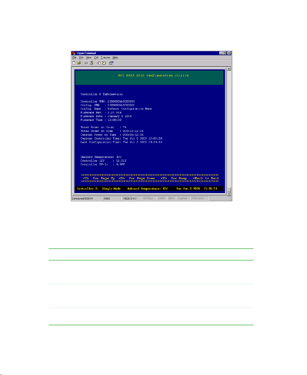
Viewing controller information
Viewing controller information
Detailed information on the RAID controller is available through the Main
Menu, and includes:
■ Controller World Wide Name (WWN)
■ Firmware information
■ Run-time information
■ Temperature and voltage information
To view controller information:
1 After the controller(s) have completed booting, press CTRL + E, then press
C
TRL + W to switch to the menu-based mode. The Main Menu opens.
www.gateway.com
13
Page 19
Chapter 2: Accessing the Configuration Utility
2 From the Main Menu select Controller Information, then press ENTER. The
Controller Information screen opens.
3 Select the controller you want to examine by using the spacebar to select
the controller, then press E
selection is listed.
The following is a brief summary of the information displayed.
Item Description
Controller WWN An 8-byte unique World Wide Name the controller uses
Configuration WWN An 8-byte World Wide Name the controller uses for
Config Name A 64-byte ASCII name used to identify a specific
14
NTER. If only one controller is present, only one
for identification. This is unique to each controller, and
preprogrammed.
identification to hosts. This can be identical to the
Controller WWN, or can be different.
controller configuration.
www.gateway.com
Page 20

Viewing controller information
Item Description
Firmware Revision The firmware version in use by the controller.
Firmware Date/Time Date and time of when the firmware was created.
Total Power on Count The number of times this controller has been power
cycled.
Total Power on Time The total length of time this controller has been powered
on.
Current Power on Time The length of time since this controller has last been
powered on or reset.
Current Controller Time This is the current time on the controller.
Last Configuration Time This is the time the controller was last configured.
Onboard Temperature This is the current temperature as measured by the
controller. If this value exceeds predefined limits, an
event will be written into the event log.
Controller Voltage Current readings for various controller and coprocessor
(if applicable) voltages.
www.gateway.com
15
Page 21

Chapter 2: Accessing the Configuration Utility
16
www.gateway.com
Page 22

Creating Disk
Arrays
This chapter provides information on creating disk arrays.
Read this chapter to learn how to:
■ Understand arrays
■ Create arrays
■ Configure array read-ahead and writeback cache
■ Assign hot spare drives
■ Delete an array
■ Expand an array
■ Trust an array
3
17
Page 23

Chapter 3: Creating Disk Arrays
Overview
Configuring a RAID system requires some planning to make sure that you define
the correct RAID levels and array options. It may be helpful to refer to the
Topology chapter in the Gateway 840 SATA RAID Enclosure User’s Guide.
This chapter will step you through the process to create the disk arrays. You
will also find sections on deleting arrays, expanding arrays, and assigning hot
spare drives. You are then directed to the next chapter for the procedures to
define the logical drives, which makes the drive array(s) available to the
operating system.
This manual assumes you have a basic understanding of RAID concepts and
terminologies.
18
www.gateway.com
Page 24

Understanding arrays
You can create an array at any time. The table below describes the drive
requirements for each RAID level.
RAID Level Minimum No. of Drives Maximum No. of Drives
0112
1212
5312
50 6 12
10 (Mirrored) 4 12
Important Before you create more than one array, you must be sure
that your host operating system supports multiple Logical
Unit Numbers (LUNs). Most operating systems do support
multiple LUNs, or have an option for it. If your operating
system does not support multiple LUNs, the host will only
be able to see one array at the first disk LUN.
Understanding arrays
Terminology
The following describes the terminology used when creating and managing
arrays.
Term Description
Array A group of drives that are combined together to create a
single large storage area. Up to 64 arrays are supported,
each containing up to 12 drives per array. There is no limit
for the drive size in the arrays.
Chunk Size This is the amount of data that is written on a single drive
before the controller moves to the next drive in the stripe.
Stripe Size This is the number of data drives multiplied by the chunk
size.
Cache Flush Array This is the array that is used to automatically flush cache
data in the situation where power has failed to some of the
drives.
www.gateway.com
19
Page 25

Chapter 3: Creating Disk Arrays
Initialization RAID 5/50 arrays must have consistent parity before they
Reserved Capacity In order to allow drives from a different family or
RAID Level 0 RAID 0 is defined as disk striping where data is striped or
can be used to protect data. Initialization writes a known
pattern to all drives in the array. If you choose not to
initialize an array, this is known as a “trusted array” and
any drive failure will result in data corruption. It is possible
to later perform a parity rewrite, which recalculates the
parity based on the current data, thus ensuring the data
and parity are consistent.
manufacturer to be used as a replacement for a drive in
an array, we recommend that a small percentage of the
drive’s capacity be reserved when creating the array. This
is user selectable, from 0 to 10 percent.
spread across one or more drives in parallel. RAID 0 is
ideal for environments in which performance (read and
write) is more important than fault tolerance or you need
the maximum amount of available drive capacity in one
volume. Drive parallelism increases throughput because
all drives in the stripe set work together on every I/O
operation. For greatest efficiency, all drives in the stripe set
must be the same capacity. Because all drives are used
in every operation, RAID 0 allows for single-threaded I/O
only (i.e., one I/O operation at a time). Environments with
many small simultaneous transactions (e.g., order entry
systems) will not get the best possible throughput.
20
RAID Level 1 RAID 1 is defined as disk mirroring where one drive is an
exact copy of the other. RAID 1 is useful for building a
fault-tolerant system or data volume, providing excellent
availability without sacrificing performance.
RAID Level 5 RAID 5 is defined as disk striping with parity where the
parity data is distributed across with parity all drives in the
volume. Normal data and parity data are written to drives
in the stripe set in a round-robin algorithm. RAID 5 is multi
threaded for both reads and writes because both normal
data and parity data are distributed round-robin. This is
one reason why RAID 5 offers better overall performance
in server applications. Random I/O benefits more from
RAID 5 than does sequential I/O, and writes take a
performance hit because of the parity calculations. RAID
5 is ideal for database applications.
www.gateway.com
Page 26

Understanding arrays
RAID Level 10 RAID 10 is defined as mirrored stripe sets (also known as
RAID 0+1). You can build RAID 10 either directly through
the RAID controller (depending on the controller) or by
combining software mirroring and controller striping (called
RAID 01).
RAID Level 50 This RAID level is a combination of RAID level 5 and RAID
level 0. Individual smaller RAID 5 arrays are striped, to give
a single RAID 50 array. This can increase the performance
by allowing the controller to more efficiently cluster
commands together. Fault tolerance is also increased, as
one drive can fail in each individual array.
Sub-array In RAID 50 applications, this is the name given to the
individual RAID 5 arrays that are striped together. Each
sub-array has one parity drive.
Optimization and drive selection for RAID 5 arrays
Typical RAID 5 implementations require a number of steps to write the data
to the drives. In order to optimize your system performance based on the type
of writes you expect in your operation, we have provided detailed information
on optimizing the performance using full strip write operations in an appendix
(see “Optimizing RAID 5 Write Performance” on page 227).
If you intend to setup a RAID 5 array and want to consider optimum
performance, you will need to consider the number of drives, parity drives, and
chunk size. You should review the information provided in “Optimizing RAID
5 Write Performance” on page 227. Additional information is provided at the
appropriate step during configuration.
www.gateway.com
21
Page 27

Chapter 3: Creating Disk Arrays
Creating arrays
Configuring the arrays involves a few basic steps. All configuration parameters
are stored on all hard drives that are members of the specific array. This makes
it possible to remove and replace controllers without requiring any
configuration changes. The configurations can be viewed or modified through
the controller’s RS-232 port.
Important We recommend that you make notes about the arrays you
Important When creating arrays and logical drives, make sure that
create in case you need to duplicate the configuration for
an array. See “Trusting an array” on page 61
you are in compliance with the following guidelines:
- Maximum drives per array = 12
- Maximum number of arrays = 64
- Maximum number of logical drives = 512
No changes are made until the configuration is saved, so it is possible to quit
at any time without affecting the current configuration as long as you do not
save those changes. Configuration can be performed while the system is active.
22
www.gateway.com
Page 28

Creating arrays
To view an array:
1 From the Main Menu, select Configuration Menu, then press ENTER. The
Configuration Menu opens.
www.gateway.com
23
Page 29

Chapter 3: Creating Disk Arrays
2 From the Configuration Menu, select View Configuration, then press ENTER.
The View Configuration Screen opens.
The following table provides a description of the fields shown on the screen.
Field Description
No. Drive number in the array.
Vendor ID Indicates the manufacturer of the drive.
Product ID Drive model number.
F/W Drive firmware version.
Ser. No. Drive serial number.
Cap. Drive capacity expressed in GBs.
EN, SL The enclosure and drive slot number, used for drive
identification.
ST The drive status, will either be “OK” or “FL.”
3 Press ESC to return to the previous screen.
24
www.gateway.com
Page 30

Creating arrays
To create an array:
1 From the Main Menu, select Configuration Menu, then press ENTER. The
Configuration Menu opens.
www.gateway.com
25
Page 31

Chapter 3: Creating Disk Arrays
2 To access the Array Configuration Menu, select Array Configuration, then
press E
The Array Configuration Menu lets you review, create, delete, or otherwise
modify the active arrays.
NTER. The Array Configuration Menu opens.
26
www.gateway.com
Page 32

Creating arrays
3 From the Array Configuration Menu, select Create Array, then press ENTER.
The Array Name screen opens.
www.gateway.com
27
Page 33

Chapter 3: Creating Disk Arrays
4 Type a name for the array (using as many as 32 characters), then press
E
NTER. The RAID Level screen opens.
28
5 Highlight the appropriate RAID level, then press ENTER. The Configuration
Typ e screen opens.
www.gateway.com
Page 34

Creating arrays
6 Select Manual Configuration, then press ENTER. The Select Chunk Size screen
opens.
The available chunk sizes are 64 K, 128 K, and 256 K. This is the amount
of data that is written on a single drive before the controller moves to the
next drive in the stripe.
To achieve optimum RAID 5 write performance you should consider setting
the chunk size based on the specified number of drives for a Full Stripe
Write when configuring RAID 5/50 arrays. See “Optimizing RAID 5 Write
Performance” on page 227 for detailed information.
The primary aim of setting a chunk size is to try to set a stripe size that
allows for full stripe writes. The stripe size is determined by the number
of data drives multiplied times the chunk size, (8 data drives × 64 K chunk
size = 512 strip size).
For maximum performance with RAID 5/50 arrays, you want to do as many
full stripe writes as possible. Typically, Windows NT, Windows 2000, and
Windows 2003 access at 64 K. Therefore, a stripe size of up to 1 MB would
mean the controller has to cluster 16 commands to perform a full stripe
write (actually 17 because of alignment). If you were to use a larger stripe
size, you run the risk of not being able to cluster sufficiently for the
application.
www.gateway.com
29
Page 35

Chapter 3: Creating Disk Arrays
In cases where you are performing larger writes to the controller, you could
go up to 2 MB for a stripe size, since you have more data to cluster. Never
exceed 2 MB for a stripe size, since the controller cannot cluster over
this size.
We recommend that you keep the stripe size to 1 MB or less for general
use, perhaps increasing it for specific applications. This stripe size is
actually the substripe size in RAID 50 cases. A 4+1 array (4 data and 1 parity
drives) with a 256 K chunk has a 1 MB stripe size, as does an 8+1 array
with 128 K stripe size, and an 8+2, RAID 50 array with 256 K chunk size.
Although 8+1 gives an even stripe size, this does not really matter for an
operating system (OS) that writes in significantly smaller chunks. So, 8+1,
10+1, or 11+1 with a chunk size of 64 K would be fine for an OS that does
64 K writes. If the OS does much larger writes, you may want to increase
the chunk size. With writeback cache enabled, the controller can keep data
and do a full stripe write.
For a single enclosure example - best all around performance:
11+1 with 64 K chunk size would yield a 704 K stripe (11×64=704)
10+2 with 128 K chunk size would yield a 640 K stripe (5×128=640)
30
When using more drives, 14+2 (64 K), or 12+3 (128 K) should be as
good as 12+4. However, we recommend that it be kept to a minimum
of 4 data drives for a subarray.
For most sequential accesses, the difference may not be too much for
different configurations. However, for large block random writes, it can
help if the stripe size is similar to the I/O size. This lets the controller
perform a partial full stripe write, where it has most of the data for a full
stripe, and can just read some from the drives to complete the stripe.
While Windows NT, Windows 2000, and Windows 2003 do 64 K accesses,
these are not aligned. If the chunk size is 64 K, every access crosses a chunk
boundary and so involves two read/modify/write commands instead of
one. However, since the controller can cluster, this problem is somewhat
offset since the controller usually can cluster sufficiently to do full stripe
writes. If it is a completely random 64 K access on Window NT, Windows
2000, or Windows 2003, a 64 K chunk is not the best. A chunk size of 128 K
or 256 K is better to minimize the number of commands that cross chunk.
Larger chunk sizes should be used if the OS is writing large blocks, or with
large sequential writes where the controller can cluster sufficiently. Always
keep the stripe size below 2 MB.
www.gateway.com
Page 36

Creating arrays
7 Select the desired chunk size from the menu, then press ENTER. The Drive
Selection Menu opens.
8 Select the drives for the new array by doing the following:
The controller will list all the available drives for each attached
enclosure(s). You can choose to add a drive to the array by highlighting
the drive, then pressing the U key. Or you can select all the available drives
by pressing the A key. Remove a drive that has been selected by pressing
the R key, or remove all of the drives selected by pressing the C key.
Tips & Tricks If you have multiple enclosures, the enclosure you are
viewing is displayed at the top of the page. To move to the
drives in the next enclosure, highlight the last drive in the
column or row and press the right or down arrow key.
www.gateway.com
31
Page 37

Chapter 3: Creating Disk Arrays
9 To continue, press the CTRL + D keys when you have completed your
selections. The Drive Capacity Reserve screen opens.
32
Tips & Tricks The drive capacity reserve determines how much drive
capacity to retain for future capacity fluctuations of
replacement drives. (This is not applicable to RAID 0
configurations.) The default is 1%.
www.gateway.com
Page 38

Creating arrays
10 Type the correct value for the drive capacity reserve (percentage), then press
E
NTER. The Sub-Array Selection screen opens.
The controller displays the number of available sub-arrays you can choose
from. In this example, the first one is a single sub-array that provides nine
data drives and one parity drive, and the second example is two sub-arrays
that provides two four-drive sub-arrays with one parity drive.
When you create a redundant array, such as a RAID 5 or 50 type, you will
always be creating at least one sub-array comprised of the data drives and
one parity drive. When a sufficient number of drives have been selected
you can choose to make multiple sub-arrays of your array. This provides
the benefits of a quicker recovery from a drive failure since only one of
the smaller sub-arrays is affected.
Tips & Tricks If this is just one single array with less than five hard drives,
choose the default of one sub-array.
www.gateway.com
33
Page 39

Chapter 3: Creating Disk Arrays
11 Select the number of sub-arrays required, then press ENTER. The
Initialize/Trust Arrays screen opens.
12 Select Initialize Array, then press ENTER. The Save Configuration screen opens.
34
For details on trusting arrays, refer to “Trusting an array” on page 61.
www.gateway.com
Page 40

Creating arrays
Important You must initialize the array before using the logical drives
created from the array.
13 Save the configuration to create the array. Click Yes , then press ENTER. You
will see a message that the configuration is being saved.
14 After it has completed the process, press any key to continue.
15 Continue with setting up the Array Read-Ahead Cache and Writeback
Cache, then go to the Hot Spare drives options.
Tips & Tricks After you have completed these tasks, go to the next
chapter. Create the logical drives and perform the LUN
assignment to complete the setup. Additionally, for more
control over the logical drives, see “SAN LUN Mapping” on
page 89 and perform your appropriate mappings.
www.gateway.com
35
Page 41

Chapter 3: Creating Disk Arrays
Configuring array read-ahead and writeback cache
The following steps will guide you through configuring the read-ahead cache
and writeback cache options for each array. Each array has a different set of
cache settings. Read-ahead cache and writeback cache thresholds work together
to allow fine tuning of the I/O performance. You will need to set these options
for each array you have created.
Read-ahead cache
The Read-Ahead function improves the data retrieval performance by allowing
the controller to read into cache a full stripe of data at one time, which greatly
improves the cache hits. For smaller transfers the Read-Ahead algorithm can
improve performance. If, for example, the stripe size is 256 KB (chunk size
multiplied by the number of data drives) and the host requests 64 KB of data,
when Read-Ahead is enabled, the controller will read in advance a full 256 KB.
When the host request the next 64 KB block, the data will already be in the
cache. Depending on the data patterns for your application, disabling the
read-ahead cache can help load balance the read and write operations, which
can increase performance.
36
www.gateway.com
Page 42

Configuring array read-ahead and writeback cache
To configure the read-ahead cache:
1 From the Main Menu, select Configuration Menu, then press ENTER. The
Configuration Menu opens.
www.gateway.com
37
Page 43

Chapter 3: Creating Disk Arrays
2 From the Configuration Menu, select Array Configuration, then press ENTER.
The Array Configuration Menu opens.
38
3 From the Array Configuration Menu, select Array Cache Configuration, then
press E
NTER. The Array Cache Configuration Menu opens.
www.gateway.com
Page 44

Configuring array read-ahead and writeback cache
4 From the Array Cache Configuration Menu, select Read-Ahead Cache, then
press E
NTER. The Select Array screen opens.
5 Press the up or down arrow keys to select an array, then press ENTER.
6 Press the up and down arrow keys to select a Read-Ahead Cache parameter
to use for the selected array, then press C
www.gateway.com
TRL
+ D to save the changes.
39
Page 45

Chapter 3: Creating Disk Arrays
The choices are Automatic, Disabled, and four pre-determined sizes. Select
Automatic (the default), and recommended setting. It lets the controller
determine the optimum setting.
Choose one of the pre-determined sizes to optimize the read performance
based on your data patterns.
7 Save the configuration changes by selecting Yes, then press ENTER.
Writeback cache
In a writeback cache operation, data is sent to the controller from the host and
the controller immediately responds to the host confirming the data was
received and written to the media. The host can then send more data. This can
significantly increase performance for host systems that only send a low
number of commands at a time. The controller caches the data, and if more
sequential data is sent from the host, it can cluster the writes together to
increase performance further. If sufficient data is sent to fill a stripe in RAID
5/50 configurations, the controller can perform a full stripe write, which
significantly reduces the write overhead associated with RAID 5/50.
Disabled will turn off the read-ahead cache.
Disabling writeback cache ensures that the data is sent to the drives before status
is returned to the host. With writeback cache enabled, if a short term power
failure occurs, the battery back-up unit provides adequate power to make sure
that cache is written to disk when the power is restored. In duplex operations,
the cache is mirrored to both controllers which provides further redundancy
in the event of a single controller failure.
Mirrored cache is designed for absolute data integrity. The cache in each storage
processor contains both primary cached data for the disk groups it owns, and
a copy of the primary data of the other storage processor. Mirrored cache
ensures that two copies of cache exist on both storage processors, before
confirming to the operating system that the write has been completed.
Below is a table from the Gateway 840 Series User Guide, which list the hold-up
times for data for the battery backup unit.
40
www.gateway.com
Page 46

Configuring array read-ahead and writeback cache
Configuration Memory Vendor
and Part Number
Measured
Current
Draw
Absolute
Maximum
Backup Time
Expected
Safe
Backup
Time
Main board only
w/256 MB
Main board
w/256 MB and
Coprocessor
w/256 MB
Kingston
KVR100X72C2/
256
Kingston
KVR100X72C2/
256
27.9mA 41.2 hours 20.6 hours
48.3mA 23.8 hours 11.9 hours
Normally, write-intensive operations will benefit through higher performance
when writeback cache is enabled on that array. Read-intensive operations, such
as a streaming server, may not benefit from writeback cache.
The writeback cache is used to optimize the write performance specific to your
data patterns. In general, larger cache sizes will increase the write performance
but can lower simultaneous read performance. The recommended size is 16 MB.
The strategy of write operations results in a completion signal being sent to
the host operating system as soon as the cache receives the data to be written.
The hard drives will receive the data at a more appropriate time in order to
increase controller performance.
www.gateway.com
41
Page 47

Chapter 3: Creating Disk Arrays
To configure the writeback cache:
1 From the Main Menu, select Configuration Menu, then press ENTER. The
Configuration Menu opens.
42
www.gateway.com
Page 48

Configuring array read-ahead and writeback cache
2 From the Configuration Menu, select Array Configuration, then press ENTER.
The Array Configuration Menu opens.
3 From the Array Configuration menu, select Array Cache Configuration Menu,
then press E
NTER. The Array Cache Configuration Menu opens.
www.gateway.com
43
Page 49

Chapter 3: Creating Disk Arrays
4 From the Array Cache Configuration Menu, select Writeback Cache, then
press
ENTER. The Writeback Parameters Select Array menu opens.
44
www.gateway.com
Page 50

Configuring array read-ahead and writeback cache
5 Press the up and down arrow keys to select an array from the list to which
you want to make changes, then press E
Parameters Menu opens.
NTER. The Writeback Cache
6 Choose a Writeback Cache parameter to use for the selected array.
Press the up and down arrow keys to select the cache, and the left and
right arrow keys to toggle from Disabled to Enabled, or choose one of the
pre-determined cache threshold sizes (1 MB, 2 MB, 4 MB, 8 MB, 16 MB,
32 MB, 64 MB, 128 MB, or 256 MB).
There are three additional options to an active Write Back Cache: Disable
if a partner controller fails or is missing, Disable if a controller battery fails,
or Disable if the array is in a critical state, (for example, during a rebuild).
Enable the options for your application. For maximum data protection, we
recommend that you enable all three options.
www.gateway.com
45
Page 51

Chapter 3: Creating Disk Arrays
7 Press CTRL
+ D to save the changes. The
Save Configuration
screen opens.
8 Select Yes to save the configuration changes, then press ENTER.
9 Press any key to continue.
46
www.gateway.com
Page 52

Assigning hot spare drives
Assigning hot spare drives
The process of configuring fault tolerant arrays includes assigning drives for
global or dedicated hot spares. In the event of a drive failure, the controller
will use a global hot spare to replace the failed drive in any array. If a dedicated
spare is assigned to the specific array, that array will use its dedicated hot spare.
This step is accomplished through the Hot Spare Configuration menu.
To configure hot spare drives:
1 From the Main Menu, select Configuration Menu, then press ENTER. The
Configuration Menu opens.
www.gateway.com
47
Page 53

Chapter 3: Creating Disk Arrays
2 From the Configuration menu, press the up or down arrow keys to select
Hot Spare Configuration menu, then press E
Menu opens.
3 To add or remove a hot spare drive, select Add or Remove Pool and Dedicated
Spare
, then press ENTER. The Add or Remove Global and Dedicated Spares
screen opens.
NTER. The Hot Spare Configuration
48
www.gateway.com
Page 54

Assigning hot spare drives
4 Press the arrow keys to highlight an available drive to use, then press S to
assign that drive as a dedicated spare. Continue to press S to display the
arrays from which you can assign the dedicated spare.
To add a drive as a pool spare (global), press the arrow keys to highlight
an available drive and press H.
To remove a drive as a hot spare, highlight the subject drive and press R,
or press C to remove all drives in the enclosure that are currently assigned
as spares.
5 After you make your selection, press CTRL + D to continue.
6 When you are prompted to save the changes, press Y to save the new hot
spare configurations.
7 Press any key to continue, then go to the next chapter, “Logical Drives”
on page 63.
www.gateway.com
49
Page 55

Chapter 3: Creating Disk Arrays
Deleting an array
To delete an array:
1 From the Main Menu, select Configuration Menu, then press ENTER. The
Configuration Menu opens.
50
www.gateway.com
Page 56

Deleting an array
2 From the Configuration Menu, select Array Configuration Menu, then press
E
NTER. The Array Configuration Menu opens.
3 From the Array Configuration Menu, select Delete Array, then press ENTER.
The Delete Array screen opens.
www.gateway.com
51
Page 57

Chapter 3: Creating Disk Arrays
4 Press the up and down arrow keys to select the array to delete, then press
E
NTER.
5 To complete the deletion, select Yes, then press ENTER.
6 Press any key to continue.
52
www.gateway.com
Page 58

Expanding an array
The Expand Array option lets you expand the capacity of your existing array
by adding more drives or adding sub-arrays.
Using a RAID 5 array example, adding more drives to the array lets you increase
the capacity of that array. If you add additional sub-arrays it requires the exact
number of drives to be available for the original sub-array. For example, if you
have an array composed of 4 data drives and 1 parity drive, you must have a
minimum of five drives available to be able to add at least 1 sub-array.
When you view the array configuration information, the RAID type and
number of drives are displayed. These drives are depicted as data drives plus
parity drives. In this example, it would be displayed as “4 Drives (3 +1)” which
indicates the array/sub-array is composed of 4 drives of which 3 are data drives
and 1 is a parity drive. If you were to add 1 sub-array to this particular
configuration, the resulting display would be “8 Drives (6+2)” in which case
you now have 6 data drives and 2 parity drives. Your RAID 5 array now becomes
a RAID 50 array because it’s composed of two sub-arrays, each sub-array has
three data drives and one parity drive.
If you are expanding a RAID 50 array by adding drives to the array, you must
add an equal number of drives to each sub-array.
Expanding an array
The process of expanding the array by adding additional sub-arrays allows for
quicker recoveries in the event of a drive failure in any one of the sub-arrays,
and the time required to rebuild the array is significantly shortened.
To add more drives to your existing arrays, refer to “Adding additional drives”
on page 54.
To add more sub-arrays to your existing array, refer to “Adding additional
sub-arrays” on page 57.
www.gateway.com
53
Page 59

Chapter 3: Creating Disk Arrays
Adding additional drives
To add additional drives:
1 From the Main Menu, select Configuration Menu, then press ENTER. The
Configuration Menu opens.
54
www.gateway.com
Page 60

Expanding an array
2 From the Configuration Menu, select Array Configuration Menu, then press
E
NTER. The Array Configuration Menu opens.
3 From the Array Configuration Menu, select Expand Array, then press ENTER.
The Select Array to Expand Menu opens.
www.gateway.com
55
Page 61

Chapter 3: Creating Disk Arrays
4 Press the up and down arrow keys to select an array to expand, then press
E
NTER. The Expansion menu opens.
5 From the Expansion menu, select Add a Number of Drives to the Array, then
press E
NTER. The Expand Array Drive Selection screen opens.
56
www.gateway.com
Page 62

6 Press the up and down arrow keys to select a drive, then press X to mark
that drive for expansion. Continue to select additional drives if necessary,
otherwise press C
You can cancel your selection by highlighting the drive and pressing R,
or remove all selected drives and start again by pressing C.
TRL + D to continue.
7 When you are prompted to save the changes, select Yes, then press ENTER.
8 Press any key to continue.
Adding additional sub-arrays
To add additional sub-arrays:
1 From the Main Menu, select Configuration Menu, then press ENTER. The
Configuration Menu opens.
Expanding an array
www.gateway.com
57
Page 63

Chapter 3: Creating Disk Arrays
2 From the Configuration menu, select Array Configuration Menu, then press
E
NTER. The Array Configuration Menu opens.
3 From the Array Configuration Menu, select Expand Array, then press ENTER.
The Select Array to Expand Menu opens.
58
www.gateway.com
Page 64

Expanding an array
4 Press the up and down arrow keys to select an array to expand, then press
E
NTER. The Expansion Menu opens.
5 Press the up and down arrow keys to select Add a Number of Sub-Arrays to
the Current Array
opens.
, then press ENTER. The Expand Array Drive Selection screen
www.gateway.com
59
Page 65

Chapter 3: Creating Disk Arrays
6 Press the up and down arrow keys to select a drive, then press X to mark
that drive for expansion. Continue to select additional drives if necessary,
otherwise press C
You can cancel your selection by highlighting the drive and pressing R,
or remove all selected drives and start again by pressing C.
7 When you are prompted to save the changes, select Yes, then press ENTER.
8 Press any key to continue.
TRL + D to continue.
60
www.gateway.com
Page 66

Trusting an array
When you create a RAID 5 or 50 array, you have the option to trust the array.
This option should only be used in environments where you fully understand
the consequences of the function. Trust array option is provided to allow
immediate access to an array for testing application purposes only.
Trust array does not calculate parity across all drives and therefore there is no
known state on the drives. As data is received from the host, parity is calculated
as normal, but it occurs on a block basis. There is no way to guarantee that
parity has been calculated across the entire drive. The parity data will be
inconsistent, so a drive failure within a trusted array will cause data loss.
To trust an array:
1 When creating a RAID 5/50 array, after you have selected the number of
sub-arrays, the Initialize Array/Trust Array menu opens, where you can
Initialize or Trust the array.
Trusting an array
2 (Test Purposes Only) Select Trust Array, then press ENTER.
www.gateway.com
61
Page 67

Chapter 3: Creating Disk Arrays
3 You are prompted to save the configuration. Select Yes to save the
configuration, then press E
4 After the process has completed, press any key to continue.
NTER.
62
www.gateway.com
Page 68

Logical Drives
This chapter provides information on creating logical
drives. Read this chapter to learn how to:
■ Configure a logical drive
■ Access the LUN configuration menu
■ View unassigned free space
■ Create a logical drive
4
63
Page 69

Chapter 4: Logical Drives
Overview
A Logical Drive is defined as a region or combination of regions of unused space
on the array(s) which makes the logical drives available to the host operating
systems as a disk. You can create up to 512 logical drives. After an array has
been created, this region is first marked as unassigned. One or more logical
drives can be created in this region or an existing logical drive can be expanded
using this region.
A logical drive can be created or expanded in 1 GB increments with a maximum
total size per drive of 2,198 GBs. This corresponds to the SCSI 32-bit addressing
limitation of 2 TB.
Important Before you create more than one logical drive, you must
Important For Microsoft
be sure that your host HBA and host operating system is
setup to handle the desired number of logical drives (LUNs
or Logical Unit Numbers). If your operating system does
not support multiple logical drives, the host will only be able
to see the first logical drive.
®
Windows® NT there is a limitation of 231
logical drives. A hot fix is available from Microsoft. See
Microsoft Knowledge Base Article-245637.
Terminology
The following table describes the terminology relating to logical drives.
Term Description
Segmentation Any logical drive can be expanded into any free region, so
it is possible to easily add capacity at any time. There is
no requirement that any additional space be contiguous.
Logical drive segmentation is completely transparent to the
host systems.
Availability To accommodate hosts with multiple ports and multiple
host systems, you can restrict a logical drive’s availability
to a particular controller port. Access can be enabled or
disabled for each port of each controller.
64
www.gateway.com
Page 70

Overview
Mapped Logical Drive
Number
Unassigned Free
Space
Each logical drive is presented to the host system with a
unique LUN. In certain cases (such as after deleting
another logical drive) it may be desirable to change the
number of the logical drive. This can be done at any time,
bearing in mind that any attached host systems may need
to be rebooted or reconfigured to retain access.
The controller keeps a map of all the space that is not
assigned to any logical drive. This space is available for
logical drive creation or expansion. Each unassigned
region is individually listed.
www.gateway.com
65
Page 71

Chapter 4: Logical Drives
Accessing the LUN configuration menu
To access the LUN configuration menu:
1 From the Main Menu, select Configuration Menu, then press ENTER. The
Configuration Menu opens.
66
www.gateway.com
Page 72

Accessing the LUN configuration menu
2 From the Configuration Menu, select LUN Configuration, then press ENTER. The
LUN Configuration Menu opens.
The LUN Configuration Menu has two menu options: one for managing logical
drives, which includes utilities for viewing, creating, deleting, and managing
LUNs, and the other is for performing SAN LUN mapping operations. For more
information see “SAN LUN Mapping” on page 89
www.gateway.com
67
Page 73

Chapter 4: Logical Drives
Viewing unassigned free space
Prior to creating a logical drive, you may want to review the available unassigned
free space. This will help you to identify the unused regions or segments for use during
the creation of your logical drives. Normally with a first time configuration this is
not necessary, since all of the space is unassigned.
To view unassigned free space:
1 From the Main Menu, select Configuration Menu, then press ENTER. The
Configuration Menu opens.
68
www.gateway.com
Page 74

Viewing unassigned free space
2 From the Configuration Menu, select LUN Configuration, then press ENTER.
The LUN Configuration Menu opens.
3 From the LUN Configuration Menu, select LUN Management, then press
E
NTER. The LUN Management Menu opens.
www.gateway.com
69
Page 75

Chapter 4: Logical Drives
4 From the LUN Management Menu, select View Unassigned Free Space, then
press E
5 Review the free space regions and note them for later use.
NTER. The Unassigned Free Space screen opens.
70
www.gateway.com
Page 76

Creating a logical drive
Creating a logical drive
To complete the process of configuring your arrays, you will need to create one or
more logical drives. Creating a logical drive from the available free space regions
presents the logical drive to the host operating system.
To create a logical drive:
1 From the Main Menu, select Configuration Menu, then press ENTER. The
Configuration Menu opens.
www.gateway.com
71
Page 77

Chapter 4: Logical Drives
2 From the Configuration menu, select LUN Configuration, then press ENTER. The
LUN Configuration Menu opens.
3 From the LUN Configuration menu, select LUN Management, then press ENTER.
The LUN Management Menu opens.
72
www.gateway.com
Page 78

Creating a logical drive
4 From the LUN Management menu, select Create Logical Drive, then press
E
NTER. The Select Unused Region Menu opens.
5 Press the up and down arrow keys to select a region you want to use for
the logical drive, then press E
screen opens.
NTER. The Number of Logical Drives to create
www.gateway.com
73
Page 79

Chapter 4: Logical Drives
Important The number shown as the default is the maximum number
6 Press the up and down arrow keys to change the desired number of Host LUNs
to create, then press E
of 1 GB logical drives you can create using the selected
free space region in the previous step. In this case the free
space region was 29 GB which yielded a total of 29, 1 GB
Host logical drives.
NTER. The LUN Size screen opens.
7 Press the up and down arrow keys to change the desired size of the LUN, then
press E
The value displayed is the default size of the logical drive that can be created
using the number of logical drives set in the previous screen based on the unused
region space. If you are creating an even number of logical drives from an odd
size value the remaining unused space is made available as unused space from
which another separate logical drive can be created. For example, if you have a
fault tolerant array with unused region of 143 GB and you create 2 logical drives
from that unused space, you will have two logical drives each with 71 GBs. After
you create the logical drives and view the unused region you will see the
remaining 1 GB available for use in another logical drive.
NTER.
8 When you are prompted to save the configuration, select Yes, then press ENTER.
9 Press any key to return to the Main Menu.
74
www.gateway.com
Page 80

Expanding a logical drive
To expand a LUN:
1 From the Main Menu, select Configuration Menu, then press ENTER. The
Configuration Menu opens.
Creating a logical drive
www.gateway.com
75
Page 81

Chapter 4: Logical Drives
2 From the Configuration menu, select LUN Configuration, then press ENTER. The
LUN Configuration Menu opens.
3 From the LUN Configuration Menu, select LUN Management, then press ENTER.
The LUN Management Menu opens.
76
www.gateway.com
Page 82

Creating a logical drive
4 From the LUN Management menu, select Expand Logical Drive, then press
E
NTER. The Select Logical Drive screen opens.
5 Select a logical drive that you want to expand, then press ENTER. The Unused
Regions For Expansion screen opens.
www.gateway.com
77
Page 83

Chapter 4: Logical Drives
6 Select the unused region into which you want to expand the logical drive,
then press E
7 Press the up and down arrow keys to change the value to the desired size,
then press E
8 When you are prompted to save the configuration, select Yes, then press
E
NTER.
NTER. The Expansion Size screen opens.
NTER.
78
9 Press any key to return to the Main Menu.
www.gateway.com
Page 84

Creating a logical drive
Setting logical drive availability
This option will make a logical drive available to a controller port and
determines whether that logical drive is seen by all or a specific host system
attached to that controller port.
To set logical drive availability:
1 From the Main Menu, select Configuration Menu, then press ENTER. The
Configuration Menu opens.
www.gateway.com
79
Page 85

Chapter 4: Logical Drives
2 From the Configuration menu, select LUN Configuration, then press ENTER.
The LUN Configuration Menu opens.
3 From the LUN Configuration menu, select LUN Management, then press
E
NTER. The LUN Management Menu opens.
80
www.gateway.com
Page 86

Creating a logical drive
4 From the LUN Management Menu, select Set Host LUN Availability, then
press E
NTER. The Select Logical Drive for Availability screen opens.
5 From the Select Logical Drive for Availability screen, select a logical drive
that you want to map to another LUN number, then press E
Modify the Logical Drive Availability screen opens.
NTER. The
6 From the Modify the Logical Drive Availability screen, select the controller
port to modify. Press E
NTER to change the property from Enable to Disable.
7 If necessary, repeat the step to change the availability of the other port.
www.gateway.com
81
Page 87

Chapter 4: Logical Drives
8 Press CTRL + D to save the changes.
9 When prompted to save the configuration, select Yes, then press ENTER.
10 Press any key to return to the Main Menu.
Deleteing a logical drive
This process will remove an existing logical drive.
To delete a logical drive:
1 From the Main Menu, select Configuration Menu, then press ENTER. The
Configuration Menu opens.
82
www.gateway.com
Page 88

Creating a logical drive
2 From the Configuration menu, select LUN Configuration, then press ENTER.
The LUN Configuration Menu opens.
3 From the LUN Configuration menu, select LUN Management, then press
E
NTER. The LUN Management Menu opens.
www.gateway.com
83
Page 89

Chapter 4: Logical Drives
4 From the LUN Management Menu, select Delete Logical Drive, then press
E
NTER. The Select a Logical Drive to Delete screen opens.
5 From the Select a Logical Drive to Delete screen, select the logical drive to
delete, then press E
NTER.
84
6 When you are prompted to save the configuration, select Yes, then press
E
NTER.
7 Press any key to return to the Main Menu.
www.gateway.com
Page 90

Creating a logical drive
Modifying a mapped LUN
This option lets you change the assigned LUN number after the logical drive
has previously been made available.
To modify a LUN number:
1 From the Main Menu, select Configuration Menu, then press ENTER. The
Configuration Menu opens.
www.gateway.com
85
Page 91

Chapter 4: Logical Drives
2 From the Configuration menu, select LUN Configuration, then press ENTER.
The LUN Configuration Menu opens.
3 From the LUN Configuration menu, select LUN Management, then press
E
NTER. The LUN Management Menu opens.
86
www.gateway.com
Page 92

Creating a logical drive
4 From the LUN Management menu, select Modify Mapped LUN Number, then
press E
opens.
NTER. The Select a Logical Drive to Modify Mapped Number screen
5 From the Select a Logical Drive to Modify Mapped Number screen, select
the logical drive whose number you intend to change, then press E
The Select a New LUN Number screen opens.
www.gateway.com
NTER.
87
Page 93

Chapter 4: Logical Drives
6 Press the up and down arrow keys to change the logical drive number to
the desired number, then press E
7 When you are prompted to save the configuration, select Yes, then press
E
NTER.
8 Press any key to return to the Main Menu.
NTER.
88
www.gateway.com
Page 94

SAN LUN
Mapping
This chapter provides information on SAN LUN mapping.
Read this chapter to learn how to:
■ Access the SAN LUN mapping configuration menu
■ View SAN LUN mappings
■ Create a SAN LUN mapping
■ Delete a SAN LUN mapping
■ Modify a SAN LUN mapping
■ View connected hosts
5
89
Page 95

Chapter 5: SAN LUN Mapping
Overview
When attaching multiple host systems in a SAN environment, it may be necessary
to more precisely control which hosts have access to which logical drives. In addition
to controlling logical drive availability on a RAID controller on a port-by-port basis,
it is also possible to further restrict access to a specific logical drive. Up to 512 SAN
LUN mappings are supported.
Terminology
The following table describes the terminology relating to SAN LUN Mapping.
Term Description
Node Name This is an eight-byte hexadecimal number, uniquely identifying
Port Name This is an eight-byte hexadecimal number, uniquely identifying
a single host system. It incorporates the World Wide Name
and two additional bytes which are used to specify the format.
a single host port. It incorporates the World Wide Name and
two additional bytes which are used to specify the format and
indicate the port number.
Mapping Name A 32-character name that can be used to help identify the host
system.
Exclusive Access A logical drive is presented to only one host system. It is not
available to any other host systems.
Read/Write Access A logical drive will allow both reads and write operations.
Read Only Access A logical drive will not allow writes.
Mapped LUN
Number
Mapping Availability Which controller ports the mapping is valid for.
90
This is the LUN number that a specific logical drive responds
to when accessed by a host. It is not necessary for this to bear
any relation to the LUN number.
www.gateway.com
Page 96

Accessing the SAN LUN mapping configuration menu
Accessing the SAN LUN mapping
configuration menu
To access the SAN LUN mapping configuration menu:
1 From the Main Menu, select the Configuration Menu, then press ENTER. The
Configuration Menu opens.
www.gateway.com
91
Page 97

Chapter 5: SAN LUN Mapping
2 From the Configuration Menu, select LUN Configuration, then press ENTER. The
LUN Configuration Menu opens.
3 From the LUN Configuration menu, select SAN LUN Mapping, then press ENTER.
The SAN LUN Mapping screen opens.
92
The SAN LUN Mapping Configuration Menu provides the options for viewing,
creating, deleting, and managing SAN LUNs, and for viewing the host systems
attached to the storage network.
www.gateway.com
Page 98

Viewing SAN LUN mappings
Viewing SAN LUN mappings
To view existing SAN LUN mappings, choose this option.
To view SAN LUN mappings:
1 From the Main Menu, select the Configuration Menu, then press ENTER. The
Configuration Menu opens.
www.gateway.com
93
Page 99

Chapter 5: SAN LUN Mapping
2 From the Configuration menu, select LUN Configuration, then press ENTER. The
LUN Configuration Menu opens.
3 From the LUN Configuration menu, select SAN LUN Mapping, then press ENTER.
The SAN LUN Mapping screen opens.
94
www.gateway.com
Page 100

Viewing SAN LUN mappings
4 From the SAN LUN Mapping Menu, select View SAN LUN Mappings, then
press E
In the example above, there are two mappings created. They have an
identical node name but different port names, indicating they are both in
the same host system. The port name is used for the mapping, and access
is only allowed on Port 0 of the controllers. Each Host HBA port can access
one logical drive, exclusively.
NTER. The View SAN LUN Mapping screen opens.
The following information is shown on the screen.
■ Mapping Name: This is the name defined by the user when creating
the SAN LUN Mapping. You may use up to 32 ASCII characters.
■ HBA SCSI ID: This is initiator (target) SCSI ID of the host system HBA
port used for the mapping.
■ Port: This is the port of the RAID Controller. The controller has two
ports, and will be listed here as “0” and “1.” They represent “P0” and
“P1” respectively.
■ Description: Below each mapping is a plain language description of
how the Controller LUN is being presented to the host system as, and
what access rights are established for the mapping. These will be
Exclusive, Shared, Read-Only.
www.gateway.com
95
 Loading...