


G1000 / GFC 700
System Maintenance Manual
Hawker Beechcraft
Model C90A/C90GT/C90GTi King Air
Contains Instructions
For Continued Airworthiness
For STC #SA01456WI-D
190-00682-01 |
November 2012 |
Revision F |

This page intentionally left blank.

© Copyright 2007-2012 Garmin Ltd. or its subsidiaries All Rights Reserved
Except as expressly provided herein, no part of this manual may be reproduced, copied, transmitted, disseminated, downloaded or stored in any storage medium, for any purpose without the express prior written consent of Garmin. Garmin hereby grants permission to download a single copy of this manual and of any revision to this manual onto a hard drive or other electronic storage medium to be viewed and to print one copy of this manual or of any revision hereto, provided that such electronic or printed copy of this manual or revision must contain the complete text of this copyright notice and provided further that any unauthorized commercial distribution of this manual or any revision hereto is strictly prohibited.
Garmin International, Inc.
1200 E. 151st Street
Olathe, KS 66062 USA
Telephone: 913-397-8200
www.garmin.com
Garmin (Europe) Ltd.
Liberty House
Bulls Copse Road
Hounsdown Business Park
Southampton, SO40 9RB, UK
Phone: +44 (0) 23 8052 4000
Fax: +44 (0) 23 8052 4004
RECORD OF REVISIONS
Revision |
Revision Date |
Description |
ECO # |
A |
11/9/2007 |
Initial release for STC |
------ |
B |
11/19/2007 |
Update Release Spec & repaginated document |
48811 |
C |
02/18/2008 |
Updated Sections 1.1, 3.8, 3.9, 4.1, 4.4, 4.7, 4.14 |
51033 |
|
|
and 4.15. Added Sections 7.21 and 7.22 |
|
D |
02/15/2010 |
Updated G1000 System Software Version to |
71674 |
|
|
0636.02. Add Loader Card Creation procedure |
|
|
|
Section 3.8.2. Add SVS/Pathways. |
|
E |
10/17/2012 |
Updated G1000 System Software Version to |
95142 |
|
|
0636.03. Added ESP. Misc updates. |
|
F |
11/5/2012 |
Minor change update (clerical) |
95629 |
DOCUMENT PAGINATION
|
|
Section |
Pagination |
|
|
|
Table of Contents |
i – vi |
|
|
|
Section 1 |
1-1 – 1-6 |
|
|
|
Section 2 |
2-1 – 2-14 |
|
|
|
Section 3 |
3-1 – 3-54 |
|
|
|
Section 4 |
4-1 – 4-40 |
|
|
|
Section 5 |
5-1 – 5-88 |
|
|
|
Section 6 |
6-1 – 6-18 |
|
|
|
Section 7 |
7-1 – 7-56 |
|
|
|
Section 8 |
8-1 – 8-14 |
|
|
|
|
|
|
Page A |
G1000/GFC700 System Maintenance Manual – C90A/C90GT/C90GTi King Air |
|||
Revision F |
|
|
190-00682-01 |
|

INFORMATION SUBJECT TO EXPORT CONTROL LAWS
This document may contain information which is subject to the Export Administration Regulations (“EAR”) issued by the United States Department of Commerce (15 CFR, Chapter VII Subchapter C) and which may not be exported, released or disclosed to foreign nationals inside or outside the United States without first obtaining an export license. The preceding statement is required to be included on any and all reproductions in whole or in part of this manual.
WARNING
This product, its packaging, and its components contain chemicals known to the State of California to cause cancer, birth defects, or reproductive harm. This Notice is being provided in accordance with California's Proposition 65. If you have any questions or would like additional information, please refer to our web site at www.garmin.com/prop65.
CAUTION
The GDU lens is coated with a special anti-reflective coating that is very sensitive to skin oils, waxes and abrasive cleaners. CLEANERS CONTAINING AMMONIA WILL HARM THE ANTI-REFLECTIVE COATING. It is very important to clean the lens using a clean, lint-free cloth and an eyeglass lens cleaner that is specified as safe for anti-reflective coatings.
IMPORTANT
All G1000 screen shots used in this document are current at the time of publication. Screen shots are intended to provide visual reference only. All information depicted in screen shots, including software file names, versions and part numbers, is subject to change and may not be up to date.
Page B |
G1000/GFC700 System Maintenance Manual – C90A/C90GT/C90GTi King Air |
Revision F |
190-00682-01 |

|
|
TABLE OF CONTENTS |
|
PARAGRAPH |
PAGE |
||
1 |
INTRODUCTION ............................................................................................................................ |
1-1 |
|
|
1.1 |
CONTENT, SCOPE, PURPOSE ........................................................................................................ |
1-1 |
|
1.2 |
ORGANIZATION ........................................................................................................................... |
1-3 |
|
1.3 |
DEFINITIONS/ABBREVIATIONS .................................................................................................... |
1-4 |
|
1.4 |
PUBLICATIONS............................................................................................................................. |
1-5 |
|
1.5 |
REVISION AND DISTRIBUTION ..................................................................................................... |
1-6 |
2 |
SYSTEM DESCRIPTION ............................................................................................................... |
2-1 |
|
|
2.1 |
EQUIPMENT DESCRIPTIONS ......................................................................................................... |
2-1 |
|
2.2 |
G1000 OPTIONAL INTERFACES ................................................................................................... |
2-9 |
|
2.3 |
ELECTRICAL POWER DISTRIBUTION.......................................................................................... |
2-10 |
|
2.4 |
SHIELD BLOCK GROUNDS ......................................................................................................... |
2-12 |
|
2.5 |
G1000 /GFC700 BLOCK DIAGRAM ........................................................................................... |
2-13 |
3 G1000 CONTROL & OPERATION............................................................................................... |
3-1 |
||
|
3.1 |
GDU 1040A AND GDU 1500 DISPLAYS ..................................................................................... |
3-1 |
|
3.2 |
GCU 475 - MFD CONTROLLER ................................................................................................... |
3-3 |
|
3.3 |
GMC 710 - AFCS CONTROLS ..................................................................................................... |
3-3 |
|
3.4 |
GMA 1347D AUDIO PANEL ........................................................................................................ |
3-4 |
|
3.5 |
G1000 NORMAL MODE ............................................................................................................... |
3-6 |
|
3.6 |
REVERSIONARY MODE ................................................................................................................ |
3-7 |
|
3.7 |
CONFIGURATION MODE OVERVIEW............................................................................................ |
3-8 |
|
3.8 |
G1000 / GFC 700 SOFTWARE INFORMATION ............................................................................ |
3-13 |
|
3.9 |
G1000 SOFTWARE/CONFIGURATION PROCEDURE .................................................................... |
3-25 |
|
3.10 |
AIRCRAFT REGISTRATION NUMBER ENTRY.............................................................................. |
3-52 |
|
3.11 |
SPLASH SCREEN LOADING ........................................................................................................ |
3-52 |
|
3.12 |
CLEARING DEFAULT USER SETTINGS ....................................................................................... |
3-53 |
4 INSTRUCTIONS FOR CONTINUED AIRWORTHINESS........................................................ |
4-1 |
||
|
4.1 |
AIRWORTHINESS LIMITATIONS ................................................................................................... |
4-1 |
|
4.2 |
SERVICING INFORMATION ........................................................................................................... |
4-3 |
|
4.3 |
MAINTENANCE INTERVALS ......................................................................................................... |
4-5 |
|
4.4 |
VISUAL INSPECTION .................................................................................................................. |
4-10 |
|
4.5 |
ELECTRICAL BONDING TEST ..................................................................................................... |
4-15 |
|
4.6 |
GRS 77 EARTH MAGNETIC FIELD UPDATES ............................................................................. |
4-18 |
|
4.7 |
GSA 8X GREASING PROCEDURE............................................................................................... |
4-18 |
|
4.8 |
FLAPS-IN-MOTION DISCRETE INPUT CHECK............................................................................. |
4-19 |
|
4.9 |
SLIP CLUTCH TORQUE CHECK PROCEDURE AND SERVO CURRENT DISPLAY CHECK .............. |
4-20 |
|
4.10 |
G1000 REDUNDANT CONNECTION CHECK ............................................................................... |
4-28 |
|
4.11 |
ENGINE DATA CHECK ............................................................................................................... |
4-31 |
|
4.12 |
TRIM ANNUNCIATOR CHECK..................................................................................................... |
4-33 |
|
4.13 |
G1000 MISCOMPARE CHECKS................................................................................................... |
4-34 |
|
4.14 |
NOSE AVIONICS COMPARTMENT FANS OPERATIONAL CHECK ................................................ |
4-36 |
|
4.15 |
INSTRUMENT PANEL FANS OPERATIONAL CHECK.................................................................... |
4-36 |
|
4.16 |
STANDBY BATTERY PERIODIC CHECKS .................................................................................... |
4-36 |
5 |
TROUBLESHOOTING ................................................................................................................... |
5-1 |
|
|
5.1 |
G1000 ALERTING SYSTEM .......................................................................................................... |
5-2 |
|
5.2 |
SYSTEM ANNUNCIATIONS ........................................................................................................... |
5-4 |
|
|
||
G1000/GFC700 System Maintenance Manual – C90A/C90GT/C90GTi King Air |
Page i |
||
190-00682-01 |
Revision F |
||

5.3 |
C90A/C90GT/C90GTI SPECIFIC ALERTS ................................................................................. |
5-27 |
5.4 |
TAWS TROUBLESHOOTING ...................................................................................................... |
5-28 |
5.5 |
SYNTHETIC VISION AND PATHWAYS TROUBLESHOOTING........................................................ |
5-29 |
5.6 |
GFC 700 AFCS TROUBLESHOOTING ........................................................................................ |
5-30 |
5.7 |
BACKUP COMMUNICATIONS PATH CHECKS.............................................................................. |
5-46 |
5.8 |
GDU 104X TROUBLESHOOTING ............................................................................................... |
5-47 |
5.9 |
GDU 104X ALERTS................................................................................................................... |
5-49 |
5.10 |
GIA 63 TROUBLESHOOTING...................................................................................................... |
5-57 |
5.11 |
GIA ALERT MESSAGES ............................................................................................................. |
5-59 |
5.12 |
GEA TROUBLESHOOTING.......................................................................................................... |
5-66 |
5.13 |
GTX TROUBLESHOOTING.......................................................................................................... |
5-67 |
5.14 |
GDL 69A TROUBLESHOOTING .................................................................................................. |
5-68 |
5.15 |
GRS 77/GMU 44 TROUBLESHOOTING ...................................................................................... |
5-70 |
5.16 |
GDC 74B TROUBLESHOOTING .................................................................................................. |
5-76 |
5.17 |
GWX 68 TROUBLESHOOTING ................................................................................................... |
5-77 |
5.18 |
GMC 710 TROUBLESHOOTING .................................................................................................. |
5-78 |
5.19 |
GCU 475 TROUBLESHOOTING................................................................................................... |
5-79 |
5.20 |
SOFTWARE/CONFIGURATION TROUBLESHOOTING ................................................................... |
5-80 |
5.21 |
BACKSHELL CONNECTORS ........................................................................................................ |
5-82 |
5.22 |
STANDBY AIRSPEED INDICATOR TROUBLESHOOTING .............................................................. |
5-86 |
5.23 |
STANDBY ALTIMETER TROUBLESHOOTING .............................................................................. |
5-87 |
5.24 |
STANDBY BATTERY TROUBLESHOOTING.................................................................................. |
5-87 |
6 EQUIPMENT REMOVAL & REPLACEMENT ......................................................................... |
6-1 |
|
6.1 |
GDU 1040A/1500 ....................................................................................................................... |
6-2 |
6.2 |
GMA 1347D AUDIO PANEL ........................................................................................................ |
6-2 |
6.3 |
GIA 63W INTEGRATED AVIONICS UNITS.................................................................................... |
6-3 |
6.4 |
GEA 71 ENGINE/AIRFRAME UNIT............................................................................................... |
6-3 |
6.5 |
GTX 33 TRANSPONDER............................................................................................................... |
6-4 |
6.6 |
GDC 74B AIR DATA COMPUTER ................................................................................................ |
6-4 |
6.7 |
GTP 59 OAT PROBE.................................................................................................................... |
6-4 |
6.8 |
GRS 77 AHRS............................................................................................................................. |
6-5 |
6.9 |
GMU 44 MAGNETOMETER.......................................................................................................... |
6-5 |
6.10 |
GDL 69A..................................................................................................................................... |
6-5 |
6.11 |
GSA 80/81 SERVOS ..................................................................................................................... |
6-6 |
6.12 |
GSM 85A / GSM 86 SERVO MOUNTS ......................................................................................... |
6-6 |
6.13 |
GCU 475...................................................................................................................................... |
6-7 |
6.14 |
GMC 710..................................................................................................................................... |
6-7 |
6.15 |
GWX 68 ...................................................................................................................................... |
6-8 |
6.16 |
CONFIGURATION MODULE REMOVAL & REPLACEMENT............................................................ |
6-9 |
6.17 |
GEA 71 BACKSHELL THERMOCOUPLE REMOVAL & REPLACEMENT ....................................... |
6-11 |
6.18 |
GPS/WAAS ANTENNAS............................................................................................................ |
6-12 |
6.19 |
ENGINE SIGNAL CONDITIONERS................................................................................................ |
6-12 |
6.20 |
SENIOR AEROSPACE PC920 SIGNAL CONDITIONING UNIT ....................................................... |
6-13 |
6.21 |
INSTRUMENT PANEL ANNUNCIATORS (PROP SYNCH AND STANDBY BATTERY)...................... |
6-14 |
6.22 |
L-3 AVIONICS (BF GOODRICH) PS-835(C OR D MODEL) EMERGENCY BATTERY ................... |
6-14 |
6.23 |
STANDBY AIRSPEED INDICATOR ............................................................................................... |
6-15 |
6.24 |
STANDBY ALTIMETER ............................................................................................................... |
6-15 |
6.25 |
STANDBY ATTITUDE INDICATOR............................................................................................... |
6-16 |
6.26 |
AVIONICS COOLING FANS ......................................................................................................... |
6-16 |
6.27 |
GDU COOLING FANS................................................................................................................. |
6-17 |
7 G1000 EQUIPMENT CONFIGURATION & TESTING............................................................. |
7-1 |
|
|
|
|
Page ii |
G1000/GFC700 System Maintenance Manual – C90A/C90GT/C90GTi King Air |
|
Revision F |
190-00682-01 |
|

7.1 |
GDU 1040/1500 MFD & PFD..................................................................................................... |
7-1 |
7.2 |
GMA 1347D AUDIO PANEL ........................................................................................................ |
7-3 |
7.3 |
GIA 63W INTEGRATED AVIONICS UNIT ................................................................................... |
7-10 |
7.4 |
GEA 71 ENGINE/AIRFRAME UNIT............................................................................................. |
7-13 |
7.5 |
GTX 33 TRANSPONDER............................................................................................................. |
7-20 |
7.6 |
GDC 74B AIR DATA COMPUTER .............................................................................................. |
7-22 |
7.7 |
GRS 77 AHRS / GMU 44 MAGNETOMETER ............................................................................. |
7-26 |
7.8 |
GDL 69A XM DATA LINK ........................................................................................................ |
7-36 |
7.9 |
GSA 80/81 SERVOS ................................................................................................................... |
7-36 |
7.10 |
GCU 475 FMS CONTROLLER.................................................................................................... |
7-37 |
7.11 |
GMC 710 AFCS CONTROLLER ................................................................................................. |
7-38 |
7.12 |
GWX 68 WEATHER RADAR ..................................................................................................... |
7-39 |
7.13 |
TRAFFIC (NON-GARMIN) SYSTEM FUNCTIONAL CHECK .......................................................... |
7-40 |
7.14 |
LIGHTNING DETECTION FUNCTIONAL CHECK .......................................................................... |
7-41 |
7.15 |
TAWS FUNCTIONAL CHECK ..................................................................................................... |
7-43 |
7.16 |
FLITECHARTS FUNCTIONAL CHECK.......................................................................................... |
7-44 |
7.17 |
CHARTVIEW FUNCTIONAL CHECK............................................................................................ |
7-45 |
7.18 |
SAFETAXI FUNCTIONAL CHECK................................................................................................ |
7-46 |
7.19 |
DME FUNCTIONAL CHECK ....................................................................................................... |
7-47 |
7.20 |
ADF FUNCTIONAL CHECK ........................................................................................................ |
7-48 |
7.21 |
AIRCRAFT WEIGHT CONFIGURATION FUNCTIONAL CHECK ..................................................... |
7-48 |
7.22 |
WEIGHT ON WHEELS AND LOW SPEED AWARENESS BAND TEST ............................................ |
7-53 |
7.23 |
ESP FUNCTIONAL CHECK ......................................................................................................... |
7-54 |
8 SYSTEM RETURN TO SERVICE PROCEDURE ...................................................................... |
8-1 |
|
8.1 |
BACKUP PATH SYSTEM TESTING ................................................................................................ |
8-2 |
8.2 |
GFC 700 GROUND CHECKOUT.................................................................................................. |
8-10 |
8.3 |
MAINTENANCE RECORDS.......................................................................................................... |
8-14 |
G1000/GFC700 System Maintenance Manual – C90A/C90GT/C90GTi King Air |
Page iii |
190-00682-01 |
Revision F |

LIST OF ILLUSTRATIONS
FIGURE |
|
PAGE |
Figure 2-1. |
C90 Electrical Distribution................................................................................................... |
2-11 |
Figure 2-2. Avionics Master Power Schematic....................................................................................... |
2-11 |
|
Figure 2-3. G1000 Component Power Sources....................................................................................... |
2-12 |
|
Figure 2-4. G1000/GFC 700 Block Diagram.......................................................................................... |
2-13 |
|
Figure 3-1. GDU 1040A Control Interface............................................................................................... |
3-1 |
|
Figure 3-2. GDU 1500 Control Interface.................................................................................................. |
3-2 |
|
Figure 3-3. G1000 Softkeys...................................................................................................................... |
3-2 |
|
Figure 3-4. MFD Controls (GCU 475) ..................................................................................................... |
3-3 |
|
Figure 3-5. AFCS Controls (GMC 710) ................................................................................................... |
3-3 |
|
Figure 3-6. GMA 1347D PN 011-01257-00 Controls .............................................................................. |
3-4 |
|
Figure 3-7. GMA 1347D PN 011-01257-20 Controls .............................................................................. |
3-5 |
|
Figure 3-8. Normal Mode ......................................................................................................................... |
3-6 |
|
Figure 3-9. Manual Reversion with MFD failure ..................................................................................... |
3-7 |
|
Figure 3-10. |
Manual Reversion with pilot PFD failure ............................................................................ |
3-7 |
Figure 3-11. SET and ACTV Softkeys and Columns............................................................................... |
3-9 |
|
Figure 3-12. Loss of Communication ..................................................................................................... |
3-10 |
|
Figure 3-13. |
Configuration Status........................................................................................................... |
3-10 |
Figure 3-14. |
Data Transmission Indicators............................................................................................. |
3-11 |
Figure 3-15. G1000 LRU Configuration File Storage ............................................................................ |
3-23 |
|
Figure 3-16. GRS/GDC Configuration Settings Storage ........................................................................ |
3-24 |
|
Figure 3-17. |
Software/Configuration Overview ..................................................................................... |
3-25 |
Figure 3-18. System Upload Page........................................................................................................... |
3-27 |
|
Figure 3-19. |
System Status ..................................................................................................................... |
3-29 |
Figure 3-20. ESP Support Configuration................................................................................................. |
3-42 |
|
Figure 3-21. Servo Mount Configuration Verification ............................................................................ |
3-43 |
|
Figure 3-22. Navigation Database Synchronization ................................................................................ |
3-49 |
|
Figure 3-24. |
Aircraft Registration........................................................................................................... |
3-52 |
Figure 4-1. Servo Gear............................................................................................................................. |
4-18 |
|
Figure 4-2 GFC Status Page ................................................................................................................... |
4-20 |
|
Figure 4-3 GFC Status Page ................................................................................................................... |
4-22 |
|
Figure 4-4 GFC Status Page ................................................................................................................... |
4-27 |
|
Figure 4-5, Standby Battery..................................................................................................................... |
4-37 |
|
Figure 4-6, Power Supply Connection.................................................................................................... |
4-39 |
|
Figure 5-1. AUX – System Status Page.................................................................................................... |
5-1 |
|
Figure 5-2. |
Alerts & Annunciations.......................................................................................................... |
5-2 |
Figure 5-3. ADVISORY Softkey Annunciation ....................................................................................... |
5-2 |
|
Figure 5-4. |
System Annunciations............................................................................................................ |
5-4 |
Figure 5-5, AFCS Annunciation Field.................................................................................................... |
5-30 |
|
Figure 5-6. GFC Status Page................................................................................................................... |
5-33 |
|
Figure 5-7. |
Magnetometer Interference Test .......................................................................................... |
5-73 |
Figure 5-8. |
Magnetometer Interference Test Complete.......................................................................... |
5-75 |
Figure 5-9. GIA 63W Backshell Connectors .......................................................................................... |
5-82 |
|
Figure 5-10. GEA 71 Backshell Connectors........................................................................................... |
5-83 |
|
Figure 5-11. GMA 1347D Backshell Connectors................................................................................... |
5-83 |
|
Figure 5-12. GTX 33/33D Backshell Connectors................................................................................... |
5-83 |
|
Figure 5-13. GDU 1040A/1500 Backshell Connector (P10401 or P15001)........................................... |
5-84 |
|
Figure 5-14. GRS 77 Backshell Connector (P771)................................................................................. |
5-84 |
|
Figure 5-15. GDC 74B Backshell Connector (P74B1)........................................................................... |
5-84 |
|
Figure 5-16. GDL 69A Backshell Connector (P69A1)........................................................................... |
5-84 |
|
Figure 5-17. GCU 475 Backshell Connector (P4751) ............................................................................ |
5-85 |
|
Figure 5-18. GMC 710 Backshell Connector (P7101)............................................................................ |
5-85 |
|
|
|
|
Page iv |
G1000/GFC700 System Maintenance Manual – C90A/C90GT/C90GTi King Air |
|
Revision F |
|
190-00682-01 |

Figure 5-19. GWX 68 Backshell Connector (P681) ............................................................................... |
5-85 |
|
Figure 5-20, Signal Conditioner Mating Connector (PVIB1)................................................................. |
5-85 |
|
Figure 6-1. |
Configuration Module Installation ......................................................................................... |
6-9 |
Figure 6-2. GEA Backshell Thermocouple............................................................................................. |
6-11 |
|
Figure 7-1. G1000 Normal Mode Check .................................................................................................. |
7-2 |
|
Figure 7-2. Marker Beacon Symbology.................................................................................................... |
7-6 |
|
Figure 7-3. AUX – GPS STATUS Page (MFD)..................................................................................... |
7-10 |
|
Figure 7-4. Normal Engine Instrument Markings (MFD) ...................................................................... |
7-13 |
|
Figure 7-5, Aircraft Registration.............................................................................................................. |
7-20 |
|
Figure 7-6. |
GRS 77 Pitch/Roll Offset Calibration Page ......................................................................... |
7-28 |
Figure 7-7, Engine Run-Up Test Page ..................................................................................................... |
7-33 |
|
Figure 7-8. Normal Mode AHRS Check ................................................................................................ |
7-35 |
|
Figure 7-9. Low Speed Awareness Band Symbolization........................................................................ |
7-53 |
|
Figure 8-1. GDU Data Verification (ARINC 429) .................................................................................... |
8-7 |
|
Figure 8-2. GIA Data Verification (ARINC429/RS-232).......................................................................... |
8-8 |
|
Figure 8-3. GIA Data Verification (RS-485) ............................................................................................. |
8-9 |
|
Figure 8-4. |
Pre-Flight Test...................................................................................................................... |
8-10 |
|
LIST OF TABLES |
|
TABLE |
|
PAGE |
Table 1-1. MDL Configurations Summary............................................................................................... |
1-1 |
|
Table 1-2. Required Documents ............................................................................................................... |
1-5 |
|
Table 1-3. |
Reference Publications ............................................................................................................ |
1-6 |
Table 3-1. |
Data Indicator Symbols ......................................................................................................... |
3-11 |
Table 3-2. |
LRU to Configuration File Relationship ............................................................................... |
3-21 |
Table 3-3. |
Default Airframe Weight Configurations.............................................................................. |
3-33 |
Table 3-4. |
Optional Airframe Weight Configurations for SW Version 0636.01.................................... |
3-33 |
Table 3-5. |
Optional Airframe Weight Configurations for SW Version 0636.02 and Subs .................... |
3-34 |
Table 4-1. |
Maintenance Intervals.............................................................................................................. |
4-5 |
Table 4-2. |
Discontinued Maintenance Intervals ....................................................................................... |
4-9 |
Table 4-3. |
Nose Section Visual Inspection Procedure............................................................................ |
4-10 |
Table 4-4. |
Nose Avionics Compartment Visual Inspection Procedure .................................................. |
4-10 |
Table 4-5. |
Pilot’s Compartment Visual Inspection Procedure................................................................ |
4-11 |
Table 4-6. |
Instrument Panel G1000 Equipment Visual Inspection Procedure ....................................... |
4-12 |
Table 4-7. |
Cabin Area Visual Inspection Procedure............................................................................... |
4-13 |
Table 4-8. |
Rear Fuselage and Empennage Visual Inspection Procedure................................................ |
4-14 |
Table 4-9, Lightning Strike Inspection Procedure ................................................................................... |
4-14 |
|
Table 4-10. Measured Torque................................................................................................................. |
4-24 |
|
Table 4-11. |
Slip Clutch Torque Settings................................................................................................. |
4-26 |
Table 4-12, Standby Battery Required Equipment .................................................................................. |
4-37 |
|
Table 5-1, SVS Troubleshooting ............................................................................................................. |
5-29 |
|
Table 5-2, |
SVS-Related Alert Messages................................................................................................. |
5-29 |
Table 5-3. AFCS Annunciation Troubleshooting ................................................................................... |
5-31 |
|
Table 5-4. AFCS General Troubleshooting ............................................................................................ |
5-32 |
|
Table 5-5. |
Magnetometer Interference Test Sequence (Example).......................................................... |
5-74 |
Table 6-1. |
Configuration Module Kit – 011-00979-00............................................................................. |
6-9 |
Table 6-2. |
Thermocouple Kit (011-00981-00) ....................................................................................... |
6-11 |
Table 7-1. |
Airspeed and Altitude Table.................................................................................................. |
7-24 |
Table 7-2. |
Vertical Speed Table ............................................................................................................. |
7-25 |
Table 7-3. Required GRS/GMU Calibrations......................................................................................... |
7-27 |
|
|
|
|
G1000/GFC700 System Maintenance Manual – C90A/C90GT/C90GTi King Air |
Page v |
|
190-00682-01 |
Revision F |
|

This page intentionally left blank
Page vi |
G1000/GFC700 System Maintenance Manual – C90A/C90GT/C90GTi King Air |
Revision F |
190-00682-01 |
1 INTRODUCTION
1.1Content, Scope, Purpose
This document provides Instructions for Continued Airworthiness (ICA) for the Garmin G1000 integrated avionics and GFC700 Automatic Flight Control System (AFCS) as installed in the C90A/C90GT/C90GTi King Air, under STC #SA01456WI-D. This document satisfies the requirements for continued airworthiness as defined by 14 CFR Part 23.1529 and Appendix G. Information in this document is required to maintain the continued airworthiness of the G1000 and GFC700.
NOTE
Various procedures herein may require operating the aircraft on the ground for extended periods. Do not conduct extended ground operations (in excess of 15 minutes) with cabin air temperatures above 40 degrees C.
1.1.1Applicability
This document applies to all Model C90A/C90GT/C90GTi King Air aircraft (herein referred to also as C90A/GT/GTi) equipped with the G1000 and optional GFC700 AFCS systems.
Modification of an aircraft by this Supplemental Type Certificate (STC) obligates the aircraft operator to include the maintenance information provided by this document in the operator’s Aircraft Maintenance Manual and the operator’s Aircraft Scheduled Maintenance Program.
1.1.2Identifying an STC Configuration
Table 1-1 lists the approved configurations for this STC as defined by the Master Drawing List (MDL), Garmin document 005-00375-30.
Software loads are governed primarily by the G1000 System Software Version number. The following table identifies the System Software Version for this STC.
NOTE
G1000 System Software Version 0636.03 is added with STC MDL Rev. 6 and is the recommended software. G1000 System Software Versions 0636.01 and 0636.02 will remain to support fielded aircraft.
Table 1-1. MDL Configurations Summary
MDL |
Aircraft |
G1000 System |
Notes |
|
Configuration |
Model |
Software Version |
||
|
||||
-1 |
C90A/C90GT King Air |
0636.01 |
STC MDL Rev. 4 Approval |
|
|
|
|
|
|
-1 |
C90A/C90GT King Air |
0636.02 |
STC MDL Rev. 5 Approval |
|
|
|
|
|
|
-1 |
C90A/C90GT/C90GTi King Air |
0636.03 |
STC MDL Rev. 6 Approval |
|
|
|
|
|
This STC addresses multiple C90A/GT/GTi configurations. These configuration variants are added by loading the applicable airframe configuration and related options. Refer the General Arrangement Drawing, Garmin Part Number 005-00375-22, for additional information.
G1000/GFC700 System Maintenance Manual – C90A/C90GT/C90GTi King Air |
Page 1-1 |
190-00682-01 |
Revision F |

IMPORTANT!
If the technician is unsure of an aircraft’s STC Configuration, perform the following steps:
1.Inspect the aircraft maintenance logs for records of which STC configuration is installed. Inspect aircraft records for signs of other alterations, including field updates and Service Bulletins.
2.Power on the G1000 system by setting the BAT switch to ON, then the EXT PWR switch to ON and finally the AVIONICS MASTER switch to ON.
3.Following MFD power-up, observe upper right section of MFD splash screen for airframe configuration.
OR
After acknowledgement of the splash screen, use the FMS knob on the GCU 475 controller to go to the AUX – SYSTEM STATUS page on the MFD. In the AIRFRAME section (upper right corner,) the display shows the current G1000 airframe configuration and system software version number.
The airframe configuration is shown in the AIRFRAME field and the system software version number is shown in the following format: ‘System Software Version XXXX.XX’. It correlates to the G1000 software used to load the software to the system:
EXAMPLE:
System Software Version ‘0636.02’ = G1000 Software P/N 006-B0636-02
The G1000/GFC 700 C90 General Arrangement Drawing, Garmin Document 005-00375-22, defines the approved G1000 software for this STC.
Page 1-2 |
G1000/GFC700 System Maintenance Manual – C90A/C90GT/C90GTi King Air |
Revision F |
190-00682-01 |

1.2Organization
The following outline briefly describes the organization of this manual:
Section 2: System Description
Provides a complete description of the type design change associated with installing the G1000 integrated cockpit system in the C90A/GT/GTi King Air. An overview of the G1000 and GFC 700 system interface is also provided.
Section 3: G1000 Control & Operation
Presents basic control and operation information specifically tailored to maintenance practices. Basic G1000 Configuration Mode operation is also described.
Section 4: Instructions for Continued Airworthiness
Provides maintenance instructions for continued airworthiness of the G1000 and GFC 700 systems.
Section 5: Troubleshooting
Provides troubleshooting information to aid in diagnosing and resolving potential problems with the G1000 and GFC 700 systems.
Section 6: G1000 Equipment Removal & Replacement
Gives instructions for the removal and replacement of G1000 and GFC700 equipment.
Section 7: G1000 Equipment Configuration & Testing
Gives instructions for loading software, configuring, and testing of G1000 equipment.
Section 8: System Return to Service Procedure
Specifies return-to-service procedures to be performed upon completion of maintenance of the G1000 system.
G1000/GFC700 System Maintenance Manual – C90A/C90GT/C90GTi King Air |
Page 1-3 |
190-00682-01 |
Revision F |

1.3 |
Definitions/Abbreviations |
ADF: |
Automatic Direction Finder |
ADTS: |
Air Data Test Set |
AFCS: |
Automatic Flight Control System |
AFM: |
Aircraft Flight Manual |
AFMS: |
Aircraft Flight Manual Supplement |
AHRS: |
Attitude Heading Reference System |
CDU: |
Control Display Unit |
CFR: |
Code of Federal Regulations |
DME: |
Distance Measuring Equipment |
EAU: |
Engine/Airframe Unit |
ESP: |
Electronic Stability and Protection |
GPS: |
Global Positioning System |
HSDB: |
High-Speed Data Bus (Ethernet) |
IAU: |
Integrated Avionics Unit |
ICS: |
Inter-Com System |
ITT: |
Interstage Turbine Temperature |
LRU: |
Line Replaceable Unit |
MFD: |
Multi-Function Flight Display |
OAT: |
Outside Air Temperature |
PFD: |
Primary Flight Display |
STBY: |
Standby |
STBY ATT: |
Standby Attitude Indicator |
STBY ALT: |
Standby Altimeter |
STBY A/S: |
Standby Airspeed Indicator |
STC: |
Supplemental Type Certificate |
TAWS: |
Terrain Awareness & Warning system |
WAAS: |
Wide Area Augmentation System |
VHF: |
Very High Frequency |
1.3.1Units of Measure
Unless otherwise stated, all units of measure are English units.
Page 1-4 |
G1000/GFC700 System Maintenance Manual – C90A/C90GT/C90GTi King Air |
Revision F |
190-00682-01 |

1.4Publications
The following documents are required by this maintenance manual to perform maintenance:
|
Table 1-2. Required Documents |
|
Part Number |
Garmin Documents |
|
|
|
|
005-00375-30 |
STC Master Drawing List |
|
|
|
|
005-W0022-00 |
Wiring Diagram, G1000/GFC 700 King C90 |
|
|
|
|
005-00375-22 |
General Arrangement, G1000/GFC700 AFCS, King Air C90 |
|
|
|
|
005-00375-19 |
GWX 68 Radar Install, King Air C90A |
|
|
|
|
005-00375-21 |
Antenna Install, King Air C90A |
|
|
|
|
005-00375-28 |
Main Instrument Panel Installation, King Air C90 |
|
|
|
|
005-00375-34 |
Electrical Equipment Install, Nose Bay, King Air C90A |
|
|
|
|
005-00375-41 |
Roll Servo Install, King Air C90A |
|
|
|
|
005-00375-42 |
Yaw Servo Install, King Air C90A |
|
|
|
|
005-00375-43 |
Pitch Servo Install, King Air C90A |
|
|
|
|
005-00375-44 |
Pitch Trim Servo Install, King Air C90A |
|
|
|
|
005-00375-53 |
Magnetometer Install, King Air C90A |
|
|
|
|
005-00375-54 |
OAT Sensor Install, King Air C90A |
|
|
|
|
005-00375-71 |
Standby Battery Install, King Air C90A |
|
|
|
|
005-00375-78 |
Cabin Speaker Amplifier Installation, King Air C90 |
|
|
|
|
005-00375-79 |
Fwd Bulkhead Connector Plate Installation, King Air C90 |
|
|
|
|
320-00326-XX |
Wire Harness Assembly, G1000/GFC 700 |
|
|
|
|
005-00375-55 |
Wire Harness Routing, Nose, King Air C90 |
|
|
|
|
005-00375-56 |
Wire Harness Routing, Cabin, King Air C90 |
|
|
|
|
005-00375-31 |
Wire Harness Routing, Tail, King Air C90 |
|
|
|
|
005-00375-23 |
Control Wheel Modification,G1000/GFC 700, King Air C90 |
|
|
|
|
005-00375-25 |
Overhead Control Panel Modification, G1000/GFC 700, King Air C90A |
|
|
|
|
005-00375-26 |
Pedestal Re-Configuration, King Air C90A |
|
|
|
|
005-00375-29 |
Circuit Breaker Panel Modification, King Air C90A |
|
|
|
|
005-00375-70 |
Circuit Breaker Panel Modification, King Air C90A |
|
|
|
|
005-00375-83 |
Glareshield Lighting Modification, King Air C90 |
|
|
|
|
|
Hawker Beechcraft Documents |
|
|
|
|
90-590024-11 |
King Air C90 Series Wiring Diagram Manual |
|
|
|
|
90-590012-13 |
King Air Model 90 Series Maintenance Manual |
|
|
|
|
101-590097-13 |
King Air Series Component Maintenance Manual |
|
|
|
|
|
Other Documents |
|
|
|
|
523-0772458-00611A |
Collins DME-42 Transceiver Repair Manual (If DME is installed) |
|
|
|
|
9016182 |
Mid-Continent Instruments - Installation Manual and Operating Instructions, |
|
4200 Series Attitude Indicator |
|
|
|
|
|
|
|
|
G1000/GFC700 System Maintenance Manual – C90A/C90GT/C90GTi King Air |
Page 1-5 |
|
190-00682-01 |
|
Revision F |

85-292-1-1033 |
Signal Conditioner Installation Manual (Meggitt Sensing Systems) |
|
|
TP-336 |
L-3 Avionics Systems – Emergency Power Supply Installation Manual, PS-835 |
|
|
NOTE
Drawings, associated with this project, which include C90, C90A, or C90A/C90GT in the title apply to the C90A, C90GT, and C90GTi unless specifically otherwise stated within the drawing or elsewhere in the STC data package.
The following publications are recommended to be on hand during the performance of maintenance activities.
|
Table 1-3. Reference Publications |
|
Part Number |
Garmin Document |
|
|
|
|
190-00682-02 |
G1000/GFC 700, King Air C90A/C90GT Airplane Flight Manual |
|
Supplement |
||
|
||
190-00664-XX |
G1000/King Air C90A/C90GT Cockpit Reference Guide |
|
|
|
|
190-00355-04 |
GDL 69/69A XM Satellite Radio Activation Instructions |
|
|
|
|
190-00907-00 |
G1000 System Maintenance Manual |
|
|
|
|
190-00303-72 |
GSA8X/GSM85(A) Installation Manual |
|
|
|
|
190-00303-83 |
GSM 86 Installation Manual |
|
|
|
|
|
Hawker Beechcraft Document |
|
|
|
|
98-39006 |
Structural Inspection and Repair Manual |
|
|
|
Generic installation manuals for individual Garmin LRUs are also available through the ‘Dealer Resource Center’ section of the Garmin web site; refer to Section 1.5 for details.
1.5Revision and Distribution
This document is required for maintaining the continued airworthiness of the aircraft. When this document is revised, every page will be revised to indicate current revision level.
Garmin Dealers may obtain the latest revision of this document on the Garmin Dealer Resource Center website.
Owner/operators may obtain the latest revision of this document from the https://fly.garmin.com/ Support page, or by contacting a Garmin dealer, contacting Garmin Product Support at 913-397-8200, toll free 866-739-5687, or using around the world contact information on https://fly.garmin.com/.
A Garmin Service Bulletin describing the revision to this document will be sent to Garmin dealers if the revision is determined to be significant.
Page 1-6 |
G1000/GFC700 System Maintenance Manual – C90A/C90GT/C90GTi King Air |
Revision F |
190-00682-01 |
2 SYSTEM DESCRIPTION
2.1Equipment Descriptions
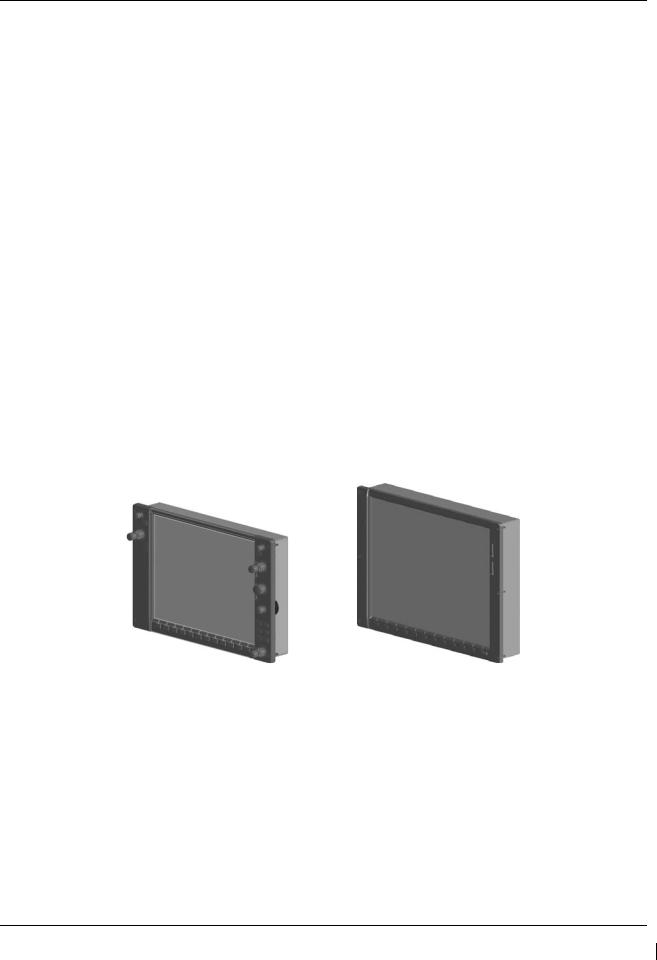
2.1.1GDU 1040A PFD (2) & GDU 1500 MFD
Two Garmin GDU 1040A displays and one GDU 1500 display are installed in the King Air instrument panel. The GDU 1040A units, 10.4 inch LCD displays with 1024x768 resolution, are configured as PFD 1 and PFD 2; the GDU 1500 unit, a 15 inch LCD display with 1024x768 resolution, is configured as a MFD. All displays provide control and display of nearly all functions of the G1000 integrated cockpit system. The PFD displays are located on either side of the MFD, with the stand-by instruments located between the Pilot’s PFD (PFD 1) and the MFD. GMA 1347 Audio Panels are located outboard of each PFD. Additionally, a GMC 710 AFCS Controller is located in the upper instrument panel, above the MFD, and a GCU 475 is installed in the pedestal. The GCU 475 provides the control interface for the MFD.
The GDU 1500 communicates with the GDU 1040A units and the GDL 69A through a high-speed data bus (HSDB) Ethernet connection. The GDU 1500 communicated with the GCU 475 via RS-232 digital interface.
The GDU 1040A units communicate with each other and the GIA 63W units through a high-speed data bus (HSDB) Ethernet connection.
Electrical power to PFD 1, MFD, and PFD 2 is provided by the triple-fed bus. The triple-fed bus is powered by the battery and both generator buses. Additionally, a secondary power source is provided to PFD 1 by the center bus, which is fed by both generator buses and the battery. Therefore, the displays power-up immediately with external or aircraft power or battery operation.
All displays are installed in the King Air panel using ¼-turn fasteners. Three CDU cooling fans are also installed behind the panel for PFD and MFD cooling.
G1000/GFC700 System Maintenance Manual – C90A/C90GT/C90GTi King Air |
Page 2-1 |
190-00682-01 |
Revision F |

2.1.2GMA 1347D Audio Panel (2)
The Garmin GMA 1347D Audio Panel integrates NAV/COM digital audio, intercom system and marker beacon controls. The C90 installation includes two GMA 1347 panels. The GMA 1347D panels provide control of all cockpit intercom/mic systems as well as NAV/COM/ILS audio. The units also provide display reversion mode control through a large red button. Power to the audio panels is provided by the avionics bus. These units only power up when the avionics master switch is turned on. The GMA 1347D units interface with the existing marker beacon antenna, as well as existing mic and phone jacks and oxygen mask mic.
2.1.3GMC 710 AFCS Control Unit
The dedicated AFCS controls on the GMC 710 allow crew control interface with the various GFC 700 autopilot / flight director functions. GMC 710 controls are discussed in detail in the G1000/King Air C90A/C90GT/C90GTi Cockpit Reference Guide. The GMC 710 is powered by the triple fed bus.
2.1.4GCU 475 FMS Control Unit
The GCU 475 functions as the primary control interface to the GDU 1500 MFD. The GCU 475 provides alphanumeric, softkey, and flight planning function keys used to interface with the G1000; the MFD does not possess any knobs or controls other than softkeys. The GCU 475 is powered by the triple-fed bus. Detailed instructions regarding the controls are discussed in the G1000 Cockpit Reference Guide.
Page 2-2 |
G1000/GFC700 System Maintenance Manual – C90A/C90GT/C90GTi King Air |
Revision F |
190-00682-01 |
2.1.5GIA 63W Integrated Avionics Unit (2)
Two Garmin GIA 63W Integrated Avionics Units (IAUs) contains the VHF COM/NAV receivers, WAAS GPS receiver, Flight Director, and system integration microprocessors. The GIAs also serve as a communication interface to all other G1000 LRUs in the system. Each GIA 63W communicates directly with the on-side GDU 1040A display using a HSDB Ethernet connection. Both GIAs are located remotely in the nose equipment bay.
Power is provided to both GIAs by the triple-fed bus. The triple-fed bus is powered by the battery and both generator buses. Additionally, a secondary power source is provided to GIA1 by the center bus, which is fed by both generator buses and the battery. The GIA 1’s COMM power supply (COM 1) is provided by No.1 Avionics Bus. GIA 2’s COMM power supply (COM 2) is provided by No.2 Avionics Bus. Therefore, both GIAs power-up immediately with external or aircraft power or battery operation, with the exception of both COMs, which will become active after selection of Avionics Master on. Both GIA 63s interface to the following equipment:
•Existing VOR/LOC/Glideslope Antenna System
•Existing VHF COM #1 & #2 Antennas
•GPS/WAAS Antennas
•GMA 1347D, #1 & #2
•GEA 71, #1 & #2
•GDU 1040A, #1 & #2
•GSA 80 (all) and GSA 81
•GRS 77, #1 & #2
•Traffic System (if installed)
The GIA 63W #1 interfaces to the following additional equipment:
•GDC 74B #1
•GTX 33 #1
•DME 42 (if installed)
The GIA 63W #2 interfaces to the following additional equipment:
•GDC 74B #2
•GTX 33 #2
•ADF 60 (if installed)
•Stormscope (if installed)
G1000/GFC700 System Maintenance Manual – C90A/C90GT/C90GTi King Air |
Page 2-3 |
190-00682-01 |
Revision F |
2.1.6GEA 71 Engine/Airframe Unit (2)
The Garmin GEA 71 Engine/Airframe Units provide engine/airframe data to the G1000 system. Data received from transducers/sensors is processed and sent to GIA 63Ws (via RS-485 digital interface), and subsequently to the GDU 1500 MFD. Engine parameters are normally displayed on the MFD. In the event of MFD failure, the engine parameters can be displayed on PFD 1 and/or PFD 2 using display reversion. The GEAs are located behind the instrument panel and are mounted in a vertical orientation. Power is received from the triple-fed bus. Both GEA units will power-up immediately with external or aircraft power or battery operation.
Each GEA interfaces to the following sensors for its onside engine:
•Oil Pressure Sensor
•Oil Temperature Sensor
•Fuel Flow Sensor (via onside Signal Conditioner)
•Turbine Speed Sensor (via onside Signal Conditioner)
•Propeller Speed Sensor(via onside Signal Conditioner)
•Torque Sensor
•Interstage Turbine Temperature (ITT) Sensor
2.1.7GTX 33 Mode S Transponder (2)
The GTX 33 Non-Extended Squitter or GTX 33 Extended Squitter (ES) (Optional) transponders communicate with the on-side GIA 63W through RS-232 digital interface. The units are mounted in the nose equipment bay. Power is provided by the No. 1 and No. 2 avionics bus for GTX 33 No. 1 and No. 2 respectively. The GTX 33 units interface with the existing transponder antennas.
NOTE
A model designation of GTX 33 in this manual will imply either the GTX 33 Non-Extend Squitter or GTX 33 Extended Squitter (ES) transponder.
Page 2-4 |
G1000/GFC700 System Maintenance Manual – C90A/C90GT/C90GTi King Air |
Revision F |
190-00682-01 |
2.1.8GDC 74B Digital Air Data Computer (2)
The Garmin GDC 74B computers compile information from the pitot/static system and various outside air temperature (OAT) and awareness sensors and provide digital air data computations to the G1000 system. The GDC 74B communicates with the GIA 63W, GDU 1040A, and GRS 77 using ARINC 429 digital interface. The unit is mounted behind the instrument panel. Power is provided to both GDC 74B units by the triple-fed bus. Additionally, a secondary power source is provided to the No. 1 computer by the center bus. The GDC 74B connects to existing pitot/static ports via existing tubing in C90A and C90GT airframes. For C90GTi airframes new pitot/static tubing and hardware is purchased from Hawker Beechcraft Company. Reference drawing Main Instrument Panel Installation KingAir C90A/C90GT, p/n 005-00375-28 for details.
2.1.9OAT Probe (2)
The Garmin GTP 59 OAT Probes provide the GDC 74B with air temperature data. The OAT probes are mounted to the bottom of the King Air fuselage at F.S. 113.5. The probes receive power directly from the GDC 74B airdata computers.
2.1.10GRS 77 Attitude & Heading Reference System (2)
The Garmin GRS 77 AHRS units provide attitude and heading information to the G1000 system. The units, mounted nose equipment bay, contain advanced tilt sensors, accelerometers, and rate sensors. The unit interfaces with the GDC 74B and GMU44 Magnetometer and utilizes GPS signals from the GIA 63Ws. Actual attitude and heading information is sent using ARINC 429 digital interface to both GDU 1040As and GIA 63Ws. Power is provided to both GRS 77 units by the triple-fed bus. Additionally, a secondary power source is provided to the No. 1 GRS 77 by the center bus. The GRS 77 interfaces with and provides power to the GMU 44 Magnetometer. The GRS 77 supplies attitude and heading information directly to the PFDs, MFD, and GIAs.
G1000/GFC700 System Maintenance Manual – C90A/C90GT/C90GTi King Air |
Page 2-5 |
190-00682-01 |
Revision F |
2.1.11GMU 44 Magnetometer (2)
The GMU 44 provides horizontal and vertical magnetic field information to the GRS 77 AHRS. This allows heading to be calculated and provides assistance during AHRS alignment. The GMU 44 units are mounted in the vertical tail. The units receive power directly from the GRS 77 units and communicate with the GRS 77 units via RS-485 digital interface.
2.1.12GDL 69A Datalink
The GDL 69A provides the interface to the GWX 68 weather radar by acting as a communications hub between the MFD and GWX68 via HSDB. The GDL 69A also provides XM Radio weather and music entertainment through means of a dedicated satellite data link. The GDL 69A is mounted behind the instrument panel. Power to the GDL 69A is received from the avionics No. 3 bus. The GDL 69A sends weather data through the HSDB bus to the MFD, where the data link interface is controlled. Digital audio is sent directly to the GMA 1347D Audio Panel.
2.1.13GWX 68 Weather Radar
The GWX 68 Airborne Weather Radar provides weather radar data output to the GDU 1500 MFD. The GWX 68 is mounted forward of the forward bulkhead at F.S. 30. Power to the GWX 68 is received from the avionics No. 2 bus. Data received from the GWX 68 is routed through the GDL 69A data link unit to the MFD via high-speed data bus (Ethernet).
Page 2-6 |
G1000/GFC700 System Maintenance Manual – C90A/C90GT/C90GTi King Air |
Revision F |
190-00682-01 |

2.1.14GSA 81 Servo, GSA 80 Servo (3) and GSM 85A/86 Servo Mount (4)
The GSA 81 (low-torque) Servo Actuator is an electromechanical unit that will provide automatic control of pitch trim. The Garmin GSA 80 (high-torque) Servo Actuator is an electromechanical unit that will provide pitch, roll and yaw damp and turn coordination. The GSA 80/81 contains a motor-control and monitor circuit board, as well as a solenoid and a brushless DC motor. The GSA 80/81 servo receives serial RS-485 data packets from the GIA 63Ws. The roll servo is located in the lower fuselage at F.S. 185. The pitch, yaw, and pitch trim servos are located in the tail. Power to the servos is received from the avionics No. 2 bus. All servos mount to a Garmin GSM 85A (optional GSM 86) Servo Mount. The GSM 85A/86 is responsible for transferring the output torque of the GSA 80 /81 servo actuators to the mechanical flight control surface linkage. The GSM 85A has a slip clutch that is field serviceable and can be adjusted to the specified torque value. The GSM 86 has a clutch cartridge that is not field serviceable, that cannot be adjusted, if the specified torque value is not within limits the clutch cartridge must be replaced.
2.1.15Comant CI428-410 / CI428-200 GPS/WAAS Antennas
The Comant CI428-410 GPS/WAAS/XM and CI428-200 GPS/WAAS antennas meet the GPS WAAS Gamma 3 specifications required for G1000. For procedural instructions on accessing the GPS antennas, refer to the King Air Model 90 Series Maintenance Manual listed in Table 1-2.
2.1.16Thommen 5A58.22.26K.28.1 Airspeed Indicator
Either a Thommen 5A58.22.26K.28.1.ET, 5A58.22.26K.28.1.FE, 5A58.22.26K.28.1.FA or 5A58.22.26K.28.1.FP unit is installed as the standby airspeed indicator. The difference between the part numbers is the location of the Vmca red radial; 80 KT, 85 KT and 90 KT respectively. The General Arrangement drawing, listed in Table 1-2, contains Table 4, which shows the applicability of each part number. The standby airspeed indicator is self illuminated and is connected to the left generator bus. The internal lights are also connected to the emergency standby battery.
2.1.17Thommen 3A43.22.35F.28.1.FU Altimeter
The Thommen 3A43.22.35F.28.1.FU altimeter with internal vibrator is used as the standby altimeter. The vibrator is powered by the No. 1 triple-fed bus. This unit is self illuminated and its internal lighting is connected to the left generator bus. Both the vibrator and the internal lighting are also connected to the emergency standby battery.
2.1.18Mid-Continent 4200-10 Attitude Indicator
The Model 4200-10 Electric Attitude Indicator is used as the standby attitude indicator and is connected to the No. 3 triple-fed bus. This unit is self illuminated and its internal lighting is connected to the left generator bus. The unit along with its internal lighting is also connected to the emergency standby battery
2.1.19L-3 PS-835(C or D Model) Emergency Standby Battery
In the event of loss of all normal electrical power, the battery is designed to provide 24 Vdc (nominal) emergency power source for the following items:
G1000/GFC700 System Maintenance Manual – C90A/C90GT/C90GTi King Air |
Page 2-7 |
190-00682-01 |
Revision F |

•standby attitude indicator (operation and internal lighting)
•standby altimeter (vibrator and internal lighting)
•standby airspeed indicator (lighting only)
The aircraft power buss provides a trickle charge to the PS-835 under normal conditions. This battery is existing in the rear fuselage of aircraft previously equipped with Collins EFIS and is installed in the nose avionics bay by this STC, on aircraft that were not previously equipped with Collins EFIS.
2.1.20 Engine Signal Conditioning
Changes to the engine signal conditioning components were initiated with STC SA01456WI-D Master Drawing List (MDL) 005-00375-30, Revision 5. The Sandia ST26 Tach Generator Unit (PN 305662-00), Senior Aerospace PC920 Signal Conditioning Unit (PN PC920-6A00PH-2A1) and the Garmin 005-00375- 93 Tach-Gen Filter Assembly were replaced by the Vibro-Meter (Meggit) Signal Conditioner Signal Conditioner. Reference the Main Instrument Panel Installation drawing listed in Table 1-2 for the locations of the Signal Conditioner Components.
2.1.20.1Sandia Aerospace ST26 Tach Generator Adapter Units (2)
The ST26 Tach Generator Adapter Units are used for converting the signal from the propeller speed and turbine speed sensors into a signal that is usable by the GEAs. The output signal from this adapter unit will be represented by a 5 VDC square wave signal at same frequency of input signal. The No. 1 ST26 (left side) unit is connected to the No. 1 Triple-fed bus and the No. 2 ST26 (right side) unit is connected to the No. 2 triple-fed bus.
The Sandia Aerospace ST26 Tach Generator Adapter Unit is applicable only to installations using STC SA01456WI-D Master Drawing List (MDL) 005-00375-30, Revision 4 and previously approved revisions.
2.1.20.2Senior Aerospace PC920 Signal Conditioning Unit
The PC920 unit was installed per this STC only for aircraft with Senior Aerospace Ketema fuel flow transducer, part number 1/2-2-81-306. The PC920 unit is used for converting the signal from the fuel flow sensor into a variable 0 to 5 VDC signal that is proportional to flow rate. The PC920 unit No. 1 channel is connected to the No. 1 triple-fed bus and the No. 2 channel is connected to the No.2 triple-fed bus. The No. 1 channel (connector P9201) converts the fuel flow signal for the left engine and the No. 2 channel (connector P9202) converts the fuel flow signal for the right engine.
The Senior Aerospace PC920 Signal Conditioner Unit is applicable only to installations using STC SA01456WI-D Master Drawing List (MDL) 005-00375-30, Revision 4 and previously approved revisions.
2.1.20.3Garmin 005-00375-93 Tach-Gen Filter Assembly (2)
The Tach-Gen Filter Assembly is used to filter out high frequency signal noise and is installed between the Sandia ST26 Signal Conditioner and both the propeller speed and turbine speed sensors. There is one tachgen filter installed for each engine. The left engine tach-gen filter is installed on the underside of the floor panel located forward of the pilots seat position. The right engine tach-gen filter is installed on the underside of the floor panel located forward of the co-pilots seat position. There are no power requirements for the tach-gen filter assembly.
The Garmin Tach-Gen Filter Assembly, 005-00375-93 is applicable only to installations using STC SA01456WI-D Master Drawing List (MDL) 005-00375-30, Revision 4 and previously approved revisions.
2.1.20.4Vibro-Meter (Meggit) Signal Conditioner (2)
Each GEA 71 receives signals from its on-side engine turbine speed sensor, propeller speed sensor and fuel flow sensors via a Vibro-Meter (Meggit) Signal Conditioner. This unit converts the signals from the engine
Page 2-8 |
G1000/GFC700 System Maintenance Manual – C90A/C90GT/C90GTi King Air |
Revision F |
190-00682-01 |

sensors to a signal usable by the GEA 71. These units are installed behind the instrument panel. Electrical power to the No. 1 Engine Signal Conditioner is provided from No. 1 Triple-fed bus and to the No. 2 Engine Signal Conditioner from No. 2 triple-fed bus. Both signal conditioners will power-up immediately with external or aircraft power or battery operation.
The Vibro-Meter (Meggit) Signal Conditioner is applicable only to installations using STC SA01456WI-D Master Drawing List (MDL) 005-00375-30, Revision 5 and subsequent approved revisions or fielded installations modified in accordance with Garmin Document 190-00682-06.
2.2G1000 Optional Interfaces
Optional equipment includes BF Goodrich WX-500 Stormscope, Traffic System, Rockwell Collins ADF60A and Rockwell Collins DME-42. Refer to wiring diagram listed in Table 1-2, for specific interface information.
G1000/GFC700 System Maintenance Manual – C90A/C90GT/C90GTi King Air |
Page 2-9 |
190-00682-01 |
Revision F |

2.3Electrical Power Distribution
This airplane uses a multi-bus system, as detailed below and in Figures 2-1 and Figure 2-2. In normal operation, all buses are automatically tied into a single-loop system where all sources supply power through individual protective devices. The battery and generator switches on the pilot’s left subpanel are used to control power from the ship battery and generators into the airplane electrical system. Switches in the cockpit that receive power from the center and triple-fed buses are identified by a white ring on the panel around the switch.
Left and Right Generator Buses: The left and right generator buses receive power from their respective left and right generators (ref. Figure 2-1). The left and right generator buses also support the No. 2 and No. 3 avionics buses, respectively, via the avionics master switch (ref. Figure 2-2). The No. 2 avionics bus supplies power to the following G1000 equipment: GMA 2, GTX 2,), GWX 68, GSA 81 servos. The No. 3 avionics bus supplies power to the GDL 69(). The No. 2 and No. 3 avionics buses also supply power to optional interface equipment.
Center Bus: The center bus is fed by two generator buses and the hot battery bus, which automatically connects those components whenever the bus ties are closed (ref. Figure 2-1). The center bus provides a secondary power source for the following G1000 equipment: PFD 1, GIA 1, GDC 1, and GRS 1.
Triple-fed Bus: The triple-fed is powered from the hot battery bus and both generator buses (ref. Figure 2-1.) The triple-fed bus also supports avionics no.1 bus via the avionics master switch (ref. Figure 2-2). The following G1000 equipment is supported by the triple-fed bus: MFD, PFD 1, PFD 2, GCU 475, GMC 710, GIA 1, GIA 2, GEA 1, GEA 2, GDC 1, GDC 2, OAT, GRS 1, and GRS 2. The No. 1 avionics bus provides power for the following G1000 equipment: GMA 1 and GTX 1. The No. 1 triple-fed bus provides power to the No.1 Sandia Aerospace ST26 tach generator adapter, No 1 channel of the Senior Aerospace PC 920 fuel flow conditioner, No.1 Vibro-Meter (Meggit) Signal Conditioner (if installed), and Thommen standby altimeter vibrator (under normal conditions.) The No 2 triple-fed bus provides power to the No. 2 Sandia Aerospace ST26 tach generator adapter, the No. 2 channel of the Senior Aerospace PC 920 fuel flow conditioner, and the No.2 Vibro-Meter (Meggit) Signal Conditioner (if installed). The No. 3 triple-fed bus provides power to the Mid-Continent standby attitude indicator (under normal conditions) and provides power for charging the L-3 emergency standby battery.
Emergency Standby Battery Function: The Standby Emergency Battery (STBY BATT) system in the King Air C90 is designed to provide uninterrupted DC power to the Standby Attitude indicator (gyro motor) and the Standby Altimeter (vibrator) from the L-3 PS-835(C or D Model) Emergency Standby Battery. In addition, the STBY BATT system supplies a fixed lighting voltage to the Standby Attitude Indicator, the Standby Altimeter, and the Standby Airspeed Indicator in the event of a total loss of DC power (ref. Figure 2-1.) For aircraft retrofitted using STC SA01456WI-D Master Drawing List (MDL) 005-00375-30, Revision 6 or later, the STBY “whiskey” compass will also receive lighting from the STBY BATT in the event of a total loss of DC power. The STBY BATT system is a redundant power source to the Standby Attitude indicator, Standby Altimeter, and the Standby Airspeed Indicator.
The electrical system is protected from excessively high current flow by the bus tie system. A bus tie sensor and relay is located between each generator bus and the center bus and also between the battery bus and the center bus. When the battery switch is on, battery bus voltage energizes and closes the relay. Similarly, when a generator or external power is brought on-line, the generator bus tie relays are energized and closed.
Page 2-10 |
G1000/GFC700 System Maintenance Manual – C90A/C90GT/C90GTi King Air |
Revision F |
190-00682-01 |
Figure 2-1. C90 Electrical Distribution
Figure 2-2. Avionics Master Power Schematic
G1000/GFC700 System Maintenance Manual – C90A/C90GT/C90GTi King Air |
Page 2-11 |
190-00682-01 |
Revision F |
Figure 2-3. G1000 Component Power Sources
2.4Shield Block Grounds
The connectors on Garmin G1000 LRUs utilize the Shield Block grounding system to provide necessary ground reference to wire shielding and/or transducers. The shield block termination method allows multiple grounds to be terminated directly to a block mounted to the connector backshell assembly. Shielding and grounding requirements for all other LRUs and connectors are shown in the respective install drawings.
Page 2-12 |
G1000/GFC700 System Maintenance Manual – C90A/C90GT/C90GTi King Air |
Revision F |
190-00682-01 |

2.5G1000 /GFC700 Block Diagram
Figure 2-4. G1000/GFC 700 Block Diagram
G1000/GFC700 System Maintenance Manual – C90A/C90GT/C90GTi King Air |
Page 2-13 |
190-00682-01 |
Revision F |

This page intentionally left blank
Page 2-14 |
G1000/GFC700 System Maintenance Manual – C90A/C90GT/C90GTi King Air |
Revision F |
190-00682-01 |
 Loading...