


Apollo£
Model SL40 VHF COMM Transceiver
Installation Manual
September 2003 560-0956-03a
¤ 2003 by Garmin AT, Inc. All rights reserved. Printed in the USA
No part of this document may be transmitted, reproduced, or copied in any form or by any means without the prior written consent of Garmin AT, Inc. Due to Garmin AT, Inc.’s commitment to constantly improve the quality and performance of our products, information contained in this document is subject to change without notice.
NAVNET and Flybrary are trademarks of Garmin AT, Inc.
II Morrow, Garmin AT, and Apollo are registered trademarks of Garmin AT, Inc.
Garmin AT, Inc. |
2345 Turner Rd., SE |
PO Box 13549 |
Salem, OR 97302 |
Salem, OR 97309 |
USA |
Phone (503) 581-8101 |
|
1-800-525-6726 |
|
In Canada 1-800-654-3415 |
|
FAX (503) 364-2138 |
|
HISTORY OF REVISIONS
|
|
|
Revision |
Date |
Description |
-- |
12/18/96 |
Initial release. |
00A |
1/30/97 |
Modified selectivity value to 7 kHz. |
-01 |
3/14/97 |
Change recommended coax from RG-58 to RG-142B |
-02 |
6/26/98 |
New software version |
-02a |
9/22/99 |
Added new connector pins and crimping tools |
-03 |
10/1/02 |
Updated ship kit information and changed II Morrow to Garmin |
|
|
AT. |
-03a |
9/15/03 |
Company name change |
IMPORTANT NOTE
“The conditions and tests required for TSO approval of this article are minimum performance standards. It is the responsibility of those desiring to install this article on or within a specific type or class of aircraft to determine that the aircraft operating conditions are within TSO standards. The article may be installed only if further evaluation by the user/installer documents an acceptable installation and is approved by the Administrator.”
Source: FAA TSO-C37d, TSO-C38d, and TSO-C128
ORDERING INFORMATION
To receive additional copies of this publication, order part # 560-0956-03a, Apollo SL40 VHF COMM Installation Manual.

NOTES

|
Table of Contents |
TABLE OF CONTENTS |
|
SECTION 1 - INTRODUCTION................................................................................................. |
1 |
ABOUT THIS MANUAL ...................................................................................................................... |
1 |
APOLLO SL40 DESCRIPTION............................................................................................................. |
1 |
FEATURES......................................................................................................................................... |
1 |
REGULATORY COMPLIANCE ............................................................................................................. |
2 |
UNPACKING THE EQUIPMENT............................................................................................................ |
3 |
PACKAGE CONTENTS ........................................................................................................................ |
3 |
OTHER REQUIRED MATERIALS ......................................................................................................... |
4 |
SPECIAL TOOLS REQUIRED ............................................................................................................... |
4 |
LICENSE REQUIREMENTS .................................................................................................................. |
4 |
SECTION 2 - INSTALLATION.................................................................................................. |
5 |
PRE-INSTALLATION INFORMATION.................................................................................................... |
5 |
INSTALLATION OVERVIEW ................................................................................................................ |
5 |
INSTALLATION CONSIDERATIONS...................................................................................................... |
5 |
MOUNTING CONSIDERATIONS.................................................................................................................................... |
5 |
MINIMUM SYSTEM CONFIGURATION.......................................................................................................................... |
5 |
EQUIPMENT MOUNTING.................................................................................................................... |
5 |
ELECTRICAL CONNECTIONS.............................................................................................................. |
7 |
POWER ...................................................................................................................................................................... |
7 |
SPEAKER AND HEADPHONE OUTPUTS........................................................................................................................ |
7 |
MICROPHONE INPUTS ................................................................................................................................................ |
7 |
TRANSMIT KEY INPUT ............................................................................................................................................... |
7 |
INTERCOM SELECTOR SWITCH................................................................................................................................... |
7 |
SERIAL INTERFACE .................................................................................................................................................... |
8 |
ANTENNA INSTALLATION AND CONNECTIONS .................................................................................. |
8 |
POST INSTALLATION CHECKOUT..................................................................................................... |
12 |
SECTION 3 - SPECIFICATIONS............................................................................................. |
15 |
ELECTRICAL ................................................................................................................................... |
15 |
PHYSICAL ....................................................................................................................................... |
15 |
ENVIRONMENTAL ........................................................................................................................... |
15 |
RECEIVER PERFORMANCE............................................................................................................... |
16 |
TRANSMITTER PERFORMANCE ........................................................................................................ |
16 |
INTERCOM PERFORMANCE.............................................................................................................. |
17 |
CONTROL INPUTS............................................................................................................................ |
17 |
ANTENNA REQUIREMENTS.............................................................................................................. |
17 |
SERIAL INTERFACE ......................................................................................................................... |
17 |
REAR CONNECTOR PINOUT............................................................................................................. |
18 |
SECTION 4 - LIMITATIONS ................................................................................................... |
19 |
INSTALLATION ................................................................................................................................ |
19 |
OPERATIONAL ................................................................................................................................ |
19 |
APPENDIX A - TROUBLESHOOTING.................................................................................. |
21 |
CONTACTING THE FACTORY FOR ASSISTANCE ................................................................................ |
21 |
Apollo SL40 Installation Manual |
i |

Table of Contents
APPENDIX B - PERIODIC MAINTENANCE ....................................................................... |
23 |
EQUIPMENT CALIBRATION ............................................................................................................. |
23 |
REFERENCE OSCILLATOR ......................................................................................................................................... |
23 |
CLEANING THE FRONT PANEL ........................................................................................................ |
23 |
APPENDIX C - ENVIRONMENTAL QUALIFICATIONS .................................................. |
25 |
APPENDIX E - SERIAL INTERFACE SPECIFICATIONS................................................. |
27 |
RS-232 INPUTS .............................................................................................................................. |
27 |
RS-232 OUTPUTS........................................................................................................................... |
29 |
LIST OF TABLES
|
|
|
TABLE 1 |
PACKAGE CONTENTS ........................................................................................................ |
3 |
TABLE 2 |
CONNECTOR PINOUT ....................................................................................................... |
18 |
TABLE 3 |
TROUBLESHOOTING GUIDE ............................................................................................. |
21 |
LIST OF ILLUSTRATIONS
|
|
|
FIGURE 1 SL40 FRONT PANEL......................................................................................................... |
2 |
|
FIGURE 2 MOUNTING FRAME ASSEMBLY ........................................................................................ |
6 |
|
FIGURE 3 CABLE ROUTING .............................................................................................................. |
6 |
|
FIGURE 4 |
COAX CONNECTOR ASSEMBLY ........................................................................................ |
9 |
FIGURE 5 |
SL40 STANDALONE WIRING DIAGRAM.......................................................................... |
10 |
FIGURE 6 |
SL40 TYPICAL AUDIO PANEL CONNECTIONS................................................................. |
11 |
FIGURE 7 |
UNIT DIMENSIONS.......................................................................................................... |
16 |
ii |
Apollo SL40 Installation Manual |

Introduction
SECTION 1 - INTRODUCTION
ABOUT THIS MANUAL
This manual describes the installation of the Apollo SL40 Comm. It is intended for use by persons certified by the Federal Aviation Administration (FAA) to install aircraft navigation devices. It includes installation and checkout procedures for the SL40 unit to standards described in FAA advisory circular AC 20-67B.
Section 1 Provides an introduction to the Apollo SL40 unit. TSO certification information is also included in this section.
Section 2 Includes installation and checkout procedures.
|
Includes complete specifications. |
Section 3 |
|
|
Includes limitations for the equipment and installation. |
Section 4 |
Appendix A Includes troubleshooting information.
Appendix B Includes periodic maintenance requirements.
Appendix C Includes the environmental qualification form.
Appendix E Includes serial data specifications.
APOLLO SL40 DESCRIPTION
The Apollo SL40 is a 760 channel VHF Comm transceiver. It is one member of the Apollo slimline series, which includes the SL40 Comm, the SL50 GPS, and the SL60 GPS/Comm.
FEATURES
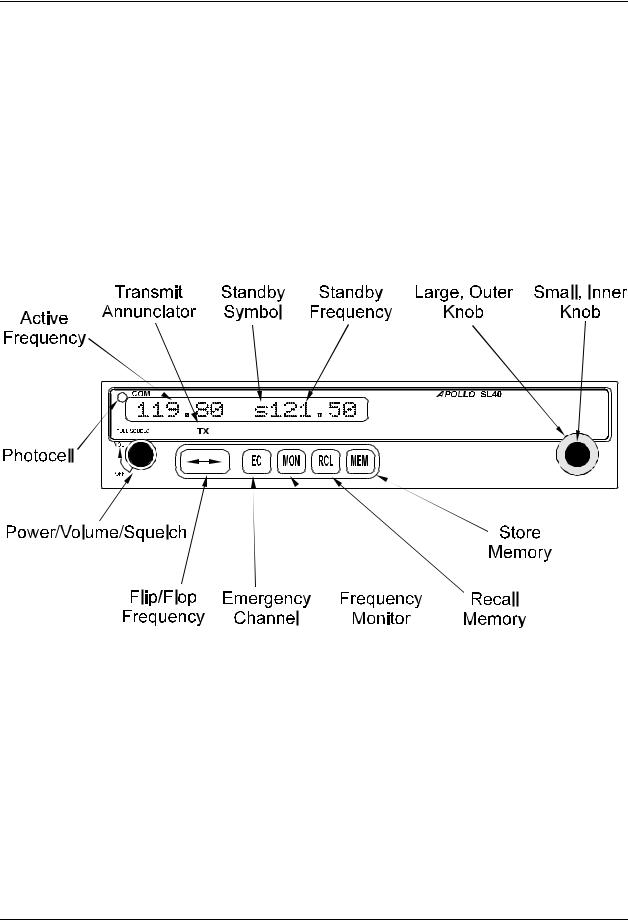
The features of the SL40 Comm include: x 760 channels
x Frequency range of 118.000 to 136.975MHz x Active and standby frequency display
x 16 character high-intensity alphanumeric LED display x Automatic display intensity
x Back-lit buttons
x Transmit status indicator
Apollo SL40 Installation Manual |
1 |
Introduction
xFrequency memory and recall functions
from remote source
eight last used
eight user stored
xWeather channels
xFrequency monitor function
xBuilt-in intercom function
xStuck mic time-out
xTwo microphone inputs
xInternal non-volatile memory - no battery required
xFull range input supply voltage
x12 watt audio amplifier
Figure 1 SL40 Front Panel
REGULATORY COMPLIANCE
The Apollo SL40 is designed and tested to meet the following TSOs: FAA TSO-C37d for transmit
FAA TSO-C38d for receive
FAA TSO-C128 for unintentional transmission (stuck mic)
The Apollo SL40 complies with the FCC requirements specified in:
CFR 47, Part 87, Aviation Services, Subpart D, Technical Requirements
CFR 47, Part 15, Radio Frequency Devices, Subpart B, Unintentional Radiators The Apollo SL40 software is designed and tested to RTCA/DO-178B, level C.
2 |
Apollo SL40 Installation Manual |

Introduction
The Apollo SL40 meets the additional standards as detailed in the Declaration of Conformity included on page 31.
Note: Unauthorized changes or modifications to the SL40 may void the compliance to required regulatory agencies and authorization for continued equipment usage.
UNPACKING THE EQUIPMENT
Carefully unpack the equipment. Visually inspect the package contents for any evidence of shipping damage. Retain all shipping containers and packaging material in case reshipment is necessary.
PACKAGE CONTENTS
As shipped from the Garmin AT, Inc. factory, the Apollo SL40 package includes most necessary items for installation other than supplies normally available at the installation shop, such as wire and cable ties, and required input and output equipment. The items included in the package are listed in Table 1.
Table 1 Package Contents
Part # |
|
Description |
Qty |
Comm unit |
|
|
|
430-6040-2xx |
Apollo SL40 Comm Transceiver |
1 |
|
Apollo SL40 Installation Kit, Part # 424-2006-2xx |
|
||
162-0100 |
or |
15 pin dsub connector shell |
1 |
162-1575 |
|
|
|
162-1008 |
|
Right angle coax plug |
1 |
202-0001 |
|
Cable tie |
2 |
204-2100 |
|
Shoulder bushing |
2 |
221-0400 |
|
4-40 x 1/4 SS pan head Phillips machine screw with lock washer |
4 |
224-0404 |
|
4-40 x 1/4 SS flat head Phillips machine screw |
6 |
245-0022 |
or |
Crimp contact for dsub, 20 to 24 awg wire |
15 |
245-0027 |
|
|
|
310-5181-01 |
Mounting frame |
1 |
|
310-5187-01 |
Connector mounting plate |
1 |
|
998-0048 |
|
3/32 hex driver |
1 |
204-0037 |
|
Edge grommet |
6” |
Apollo SL40 Manual Kit, Part # 564-0064-2xx |
|
||
560-0954-xx |
SL40 User’s manual |
1 |
|
560-0956-xx |
SL40 Installation manual |
1 |
|
Apollo SL40 Installation Manual |
3 |

Introduction
OTHER REQUIRED MATERIALS
The SL40 is intended for use with standard aviation accessories. The following items are required for the installation:
x comm antenna with cables x a microphone
x a speaker or headphone
These items may be installed dedicated to the SL40 comm or by connections to an audio panel.
SPECIAL TOOLS REQUIRED
Crimp Tool
A crimp tool meeting MIL specification M22520/1-01 and a positioner/locater are required to ensure consistent, reliable crimp contact connections for the rear d-sub connectors. These tools are available from:
For pin p/n 245-0022 |
|
|
Astro Tool Corp. |
Phone (503) 642-9853 |
|
21615 SW TV Highway |
Fax |
(503) 591-7766 |
Beaverton, OR 97006 |
|
|
Crimp tool: |
Astro Tool part #615708 |
|
Positioner: |
Astro Tool part #616356 |
|
For pin p/n 245-0027 |
|
|
ITT Cannon |
Phone (714) 261-5300 |
|
1851 E. Deere Ave. |
Fax |
(714) 575-8324 |
Santa Ana, CA 92705-6500 |
|
|
Insertion tool: |
ITT part # 274-7006-000 (Desc. CIET-20HD) |
|
Regular duty Crimp tool: |
ITT part #995-0001-585 (Desc. M22520/1-01) |
|
Regular duty Locator tool: |
ITT part #995-0001-244 (Desc. TH25) |
|
Heavy duty Crimp tool: |
ITT part #995-0001-584 (Desc. M22520/2-01) |
|
Heavy duty Locator tool: |
ITT part #995-0001-604 (Desc. M22520/2-08) |
|
LICENSE REQUIREMENTS
An aircraft radio station license is required for operation of the transmitter once installed in the aircraft. An application must be submitted on FCC Form 404, which may be obtained from the FCC in Washington, DC, or any of its field offices. Procedures for applications are in CFR 47, Part 87, Aviation Services, Subpart B, Applications and Licenses.
4 |
Apollo SL40 Installation Manual |
Installation
SECTION 2 - INSTALLATION
This section describes the installation of the Apollo SL40 including mounting, wiring, and connections. A post installation check-out procedure is included at the end of this section.
PRE-INSTALLATION INFORMATION
Always follow good avionics installation practices per FAA Advisory Circulars (AC) 43.131A, 43.13-2A, and AC 20-67B, or later FAA approved revisions of these documents.
Follow the installation procedure in this section as it is presented for a successful installation. Read the entire section before beginning the procedure. Perform the post installation checkout before closing the work area in case problems occur.
INSTALLATION OVERVIEW
A successful installation should start with careful planning including determination of mounting location for the SL40, antenna mounting, connections to microphones, speakers, and headphones, cable routing, and other required modifications. Once the mounting location has been determined, prepare the mounting frame for installation. It may be easier to complete the wiring harness and attach the connectors to the mounting frame before installing the mounting frame.
INSTALLATION CONSIDERATIONS
MOUNTING CONSIDERATIONS
The SL40 is designed to mount in the avionics stack in the aircraft instrument panel within easy view and reach of the pilot. The standard package includes a mounting frame for ease of mounting, connections, and service of the unit. Allow an additional one inch clearance to the rear of the mounting frame for connectors and cables.
For typical installations, the SL40 does not require external cooling. When mounting the SL40, leave a clearance of 1/8 to 1/4 inch between avionics to allow for circulation.
MINIMUM SYSTEM CONFIGURATION
The SL40 requires connections to the following equipment as a minimum: x power input
x speaker or headphone output x microphone input
x an antenna
EQUIPMENT MOUNTING
Once the cable assemblies have been made, attach the 15 pin dsub and coaxial cable connectors to the rear connector mounting plate and the mounting frame as illustrated in Figure 2 and Figure 3. Route the wiring bundle as appropriate. The rear connector plate should be attached to the mounting frame before installing the frame in the instrument panel. The rear connector plate can be used to tie down the cable assemblies. Connect the shield grounds directly to the connector mounting plate.
Apollo SL40 Installation Manual |
5 |

Installation
Figure 2 Mounting Frame Assembly
Figure 3 Cable Routing
Once the cable assemblies are complete and the connectors are attached to the mounting frame, install the mounting frame assembly in the instrument panel. Be sure to use low profile
6 |
Apollo SL40 Installation Manual |
 Loading...