

Page 1
USER INSTRUCTIONS MANUAL
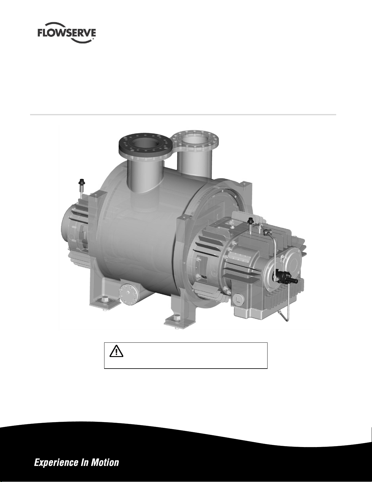
Sier-Bath® MP1
User
Instructions
Manual
Multiphase Twin Screw Rotary Pumps
PCN= 26999958– 10/12 (E). Original instructions
These instructions must be read prior to installing,
operating, using, and maintaining this equipment.
Page 2

MP1 USER INSTRUCTIONS ENGLISH 26999958 – 10-12
CONTENTS
PAGE
CONTENTS ............................................................. II
INDEX .................................................................... III
1 INTRODUCTION AND SAFETY ....................... 4
1.1 General .......................................................... 4
1.2 CE marking and approvals .............................. 4
1.3 Disclaimer ...................................................... 4
1.4 Copyright ........................................................ 4
1.5 Duty conditions ............................................... 4
1.6 Safety ............................................................ 5
1.7 Nameplate and warning labels ........................ 9
1.8 Specific machine performance ...................... 10
1.9 Noise level.................................................... 10
2 TRANSPORT AND STORAGE ....................... 11
2.1 Consignment receipt and unpacking ............. 11
2.2 Handling ....................................................... 11
2.3 Lifting ................................ ........................... 11
2.4 Storage ........................................................ 11
2.5 Recycling and end of product life .................. 12
3 PUMP DESCRIPTION .................................... 12
3.1 Configurations .............................................. 12
3.2 Name structure ............................................. 12
3.3 Design of major parts.................................... 12
3.4 Performance and operating limits.................. 13
3.5 Table of Engineering Data (Table 3) .............. 14
4 INSTALLATION .............................................. 14
4.1 Location ....................................................... 14
4.2 Part assemblies ............................................ 14
4.3 Foundation ................................................... 15
4.4 Baseplate installation .................................... 15
4.5 Initial alignment ............................................ 15
4.6 Grouting ....................................................... 17
4.7 Piping ........................................................... 18
4.8 Pressure gauges .......................................... 19
4.9 Final shaft alignment check .......................... 19
4.10 Electrical connections ................................. 19
4.11 Protection systems...................................... 20
PAGE
6 MAINTENANCE ............................................. 27
6.1 General ........................................................ 27
6.2 Maintenance schedule ................................. 27
6.3 Spare parts .................................................. 28
6.4 Recommended spare parts (Table 7) ........... 29
6.5 Tools required .............................................. 29
6.6 Torques for fasteners ................................... 29
6.7 Renewal of clearances ................................. 29
6.8 Disassembly ................................................ 29
6.9 Removing inner casing from outer casing ..... 31
6.10 Examination of parts .................................. 31
6.11 Inserting inner casing into outer casing ....... 31
6.12 Re-assembly .............................................. 32
6.13 Free movement .......................................... 33
6.14 Timing gear replacement ............................ 33
7 FAULTS; CAUSES AND REMEDIES ............. 36
8 PARTS LIST AND DRAWINGS ...................... 38
8.1 Sectional Drawing – Typical ......................... 38
8.2 General Arrangement Drawing ..................... 42
9 CERTIFICATION ........................................... 44
10 OTHER RELEVANT DOCUMENTATION AND
MANUALS ..................................................... 44
10.1 Supplementary User Instruction manuals ... 44
10.2 Change notes ............................................ 44
10.3 Additional sources of information ................ 44
11 OPTIONAL EQUIPMENT AND
ARRANGEMENTS......................................... 44
11.1 Jacketed components. ............................... 44
NOTES: ................................................................ 45
NOTES: ................................................................ 47
5 COMMISSIONING, START-UP, OPERATION
AND SHUTDOWN .......................................... 20
5.1 Pre-commissioning procedure ...................... 20
5.2 Lubricants................................................... 21
5.3 Direction of rotation ...................................... 22
5.4 Guarding ...................................................... 23
5.5 Priming and auxiliary supplies....................... 23
5.6 Starting the pump ......................................... 23
5.7 High temperature start up ............................. 23
5.8 Post start-up ................................................ 23
5.9 Running the pump ........................................ 24
5.10 Stopping and shutdown .............................. 25
5.11 Hydraulic, mechanical and electrical duty .... 25
ii flowserve.com
Page 3

INDEX
PAGE
Alignment of shafting (see 4.5 and 4.9) ........... 15, 19
CE marking and approvals (1.2) ............................... 4
Clearances (see 6.7, Renewal clearances) ............ 29
Commissioning and operation (see 5) .................... 20
Configurations (3.1) ............................................... 12
Direction of rotation (5.3) ........................................ 22
Dismantling (see 6.8, Disassembly) ....................... 29
Duty conditions (1.5) ................................................ 4
Electrical connections (4.10) .................................. 19
Examination of parts (6.10) .................................... 31
Grouting (4.6) ........................................................ 17
Guarding (5.4) ....................................................... 23
Handling (2.2) ........................................................ 11
Hydraulic, mechanical and electrical duty (5.11) ..... 25
Lifting (2.3) ............................................................ 11
Location (4.1)......................................................... 14
Lubrication schedule (see 5.2, Pump lubricants) .... 21
Maintenance schedule (6.2) ................................... 27
Piping (4.7) ............................................................ 18
Priming and auxiliary supplies (5.5) ........................ 23
Reassembly (see 6.12) .......................................... 32
Replacement parts (see 6.3) .................................. 28
Safety, protection systems (see 1.6 and 4.11) ... 5, 20
Sound level (see 1.9, Noise level) .......................... 10
Specific machine performance (1.8) ....................... 10
Starting the pump (5.6) .......................................... 23
Stopping and shutdown (5.10) ............................... 25
Storage (2.4).......................................................... 11
Tools required (6.5) ............................................... 29
Torques for fasteners (6.6) ..................................... 29
MP1 USER INSTRUCTIONS ENGLISH 26999958 – 10-12
iii flowserve.com
Page 4
MP1 USER INSTRUCTIONS ENGLISH 26999958 – 10-12
1 INTRODUCTION AND SAFETY
1.1 General
These instructions must always be kept
close to the product's operating location or
directly with the product.
Flowserve's products are designed, developed and
manufactured with state-of-the-art technologies in
modern facilities. The unit is produced with great
care and commitment to continuous quality control,
utilising sophisticated quality techniques, and safety
requirements.
We are committed to continuous quality
improvement and being at your service for any
further information about the product in its
installation and operation or about its support
products, repair and diagnostic services.
These instructions are intended to facilitate
familiarization with the product and its permitted use.
Operating the product in compliance with these
instructions is important to help ensure reliability in
service and avoid risks. The instructions may not
take into account local regulations; ensure such
regulations are observed by all, including those
installing the product. Always coordinate repair
activity with operations personnel, and follow all plant
safety requirements and applicable safety and health
laws and regulations.
These instructions should be read prior to
installing, operating, using and maintaining the
equipment in any region worldwide. The
equipment must not be put into service until all
the conditions relating to safety noted in the
instructions, have been met. Failure to follow
and apply the present user instructions is
considered to be misuse. Personal injury,
product damage, delay or failure caused by
misuse are not covered by the Flowserve
warranty.
1.2 CE marking and approvals
It is a legal requirement that machinery and
equipment put into service within certain regions of
the world shall conform with the applicable CE
Marking Directives covering Machinery and, where
applicable, Low Voltage Equipment, Electromagnetic
Compatibility (EMC), Pressure Equipment Directive
(PED) and Equipment for Potentially Explosive
Atmospheres (ATEX).
Where applicable, the Directives and any additional
Approvals, cover important safety aspects relating to
machinery and equipment and the satisfactory
provision of technical documents and safety
instructions. Where applicable this document
incorporates information relevant to these Directives.
To establish approvals and if the product itself is CE
marked, check the serial number plate and the
Certification (See section 9 CERTIFICATION).
1.3 Disclaimer
Information in these User Instructions is
believed to be complete and reliable. However,
in spite of all of the efforts of Flowserve
Corporation to provide comprehensive
instructions, good engineering and safety
practice should always be used.
Flowserve manufactures products to exacting
International Quality Management System
Standards as certified and audited by external
Quality Assurance organisations. Genuine parts
and accessories have been designed, tested and
incorporated into the products to help ensure their
continued product quality and performance in use.
As Flowserve cannot test parts and accessories
sourced from other vendors the incorrect
incorporation of such parts and accessories may
adversely affect the performance and safety features
of the products. The failure to properly select, install
or use authorised Flowserve parts and accessories
is considered to be misuse. Damage or failure
caused by misuse is not covered by Flowserve's
warranty. In addition, any modification of Flowserve
products or removal of original components may
impair the safety of these products in their use.
1.4 Copyright
All rights reserved. No part of these instructions
may be reproduced, stored in a retrieval system or
transmitted in any form or by any means without
prior permission of Flowserve Pump Division.
1.5 Duty conditions
This product has been selected to meet the
specifications of your purchaser order. The
acknowledgement of these conditions has been sent
separately to the Purchaser. A copy should be kept
with these instructions.
Page 4 of 48 flowserve.com
Page 5
The product must not be operated beyond
the parameters specified for the application. If
there is any doubt as to the suitability of the
product for the application intended, contact
Flowserve for advice, quoting the serial number.
If the conditions of service on your purchase order
are going to be changed (for example pumping,
temperature or duty) it is requested that you/the user
seek our written agreement before start up.
1.6 Safety
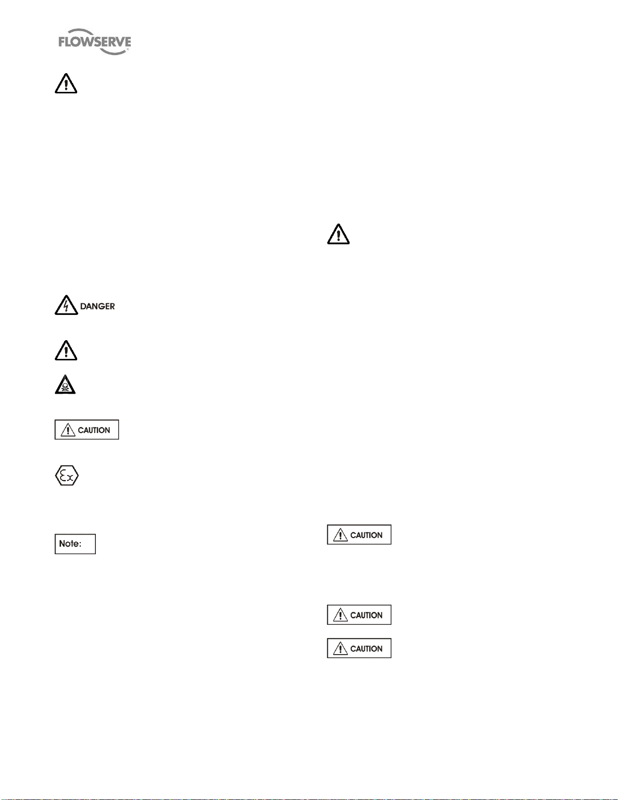
1.6.1 Summary of safety markings
These user instructions contain specific safety
markings where non-observance of an instruction
would cause hazards. The specific safety markings
are:
This symbol indicates electrical safety
instructions where non-compliance would affect
personal safety.
This symbol indicates safety instructions where
non-compliance would affect personal safety.
This symbol indicates safety instructions where
non-compliance would affect protection of a safe life
environment.
This symbol indicates safety
instructions where non-compliance would affect the
safe operation or protection of the pump or pump unit.
This symbol indicates explosive atmosphere
zone marking according to ATEX. It is used in
safety instructions where non-compliance in the
hazardous area would cause the risk of an
explosion.
This sign is not a safety symbol but
indicates an important instruction in the assembly
process.
1.6.2 Personnel qualification and training
All personnel involved in the operation, installation,
inspection and maintenance of the unit must be
qualified to carry out the work involved. If the
personnel in question do not already possess the
necessary knowledge and skill, appropriate training
and instruction must be provided. If required the
operator may commission the manufacturer/supplier
to provide applicable training.
MP1 USER INSTRUCTIONS ENGLISH 26999958 – 10-12
Always coordinate repair activity with operations and
health and safety personnel, and follow all plant
safety requirements and applicable safety and
health laws and regulations.
1.6.3 Safety action
This is a summary of conditions and actions to
prevent injury to personnel and damage to the
environment and to equipment. (For products
used in potentially explosive atmospheres
section 1.6.4 also applies.)
RELIEF VALVE PIPED BACK TO THE
SUCTION PIPE REQUIRED
The Twin Screw Pumps are positive displacement
pumps and will build up considerable pressure if
discharge line is blocked.
Customer shall include a properly sized safety relief
valve for the maximum expected flow at the
maximum expected operating pressure + 10% or the
maximum allowed working pressure (MAWP),
whichever is the lowest. Safety relief valve shall be
connected close to the discharge of the pump. The
pipeline discharging from the safety relief valve
should go back to the suction tank, if at all possible;
if not, it could be connected to the suction line of the
pump but only if well upstream so as to not create
excessive combined pressure. This discharge line
shall not be blocked at all. Customer shall also
include additional provisions to stop the process if
the discharge pressure is above the maximum
allowable pressure criteria; the pump shall not be
recirculating the flow for other than a very short time
due to the safety risk of the temperature exceeding
the allowable limit.
PREVENT EXCESSIVE EXTERNAL
PIPE LOAD
Do not use pump as a support for piping. Do not
mount expansion joints, unless allowed by
Flowserve in writing, so that their force, due to
internal pressure, acts on the pump flange.
ENSURE CORRECT LUBRICATION
START THE PUMP WITH OUTLET
VALVE FULLY OPENED
(Unless otherwise instructed at a specific point in the
user instructions.) This is recommended to minimize
the risk of overloading and damaging the pump
motor at zero flow. The pump outlet control valve
Page 5 of 48 flowserve.com
Page 6
MP1 USER INSTRUCTIONS ENGLISH 26999958 – 10-12
may need to be adjusted to comply with the duty
following the run-up process.
NEVER RUN THE PUMP DRY
INLET VALVES TO BE FULLY OPEN
WHEN PUMP IS RUNNING
Running the pump at zero flow or below the
recommended minimum flow continuously will cause
damage to the seals.
DO NOT RUN THE PUMP AT
ABNORMALLY HIGH FLOWRATES OR
ABNORMALLY LOW/HIGH DIFFERENTIAL
PRESSURES.
Operating at flow rates higher than specified can
overload the motor and/or cause cavitation and
vibration and/or low pressure at the seal chamber
potentially affecting the mechanical seals. Low
differential pressure may create too low bearings’
loads and skidding. High differential pressure may
create too high bearing loads. Both cases affect the
bearings’ life.
NEVER DO MAINTENANCE WORK
WHEN THE UNIT IS CONNECTED TO POWER
HAZARDOUS LIQUIDS
When the pump is handling hazardous liquids care
must be taken to avoid exposure to the liquid by
appropriate sitting of the pump, limiting personnel
access and by operator training. If the liquid is
flammable and/or explosive, strict safety procedures
must be applied.
DRAIN THE PUMP AND ISOLATE
PIPEWORK BEFORE DISMANTLING THE PUMP
The appropriate safety precautions should be taken
where the pumped liquids are hazardous.
FLUORO-ELASTOMERS (When fitted.)
When a pump has experienced temperatures over
250 ºC (482 ºF), partial decomposition of fluoro-
elastomers (e.g. Viton) will occur. In this condition
these are extremely dangerous and skin contact
must be avoided.
HANDLING COMPONENTS
Many precision parts have sharp corners and the
wearing of appropriate safety gloves and equipment
is required when handling these components. To lift
heavy pieces above 25 kg (55 lb) use a crane
appropriate for the mass and in accordance with
current local regulations.
GUARDS MUST NOT BE REMOVED WHILE
THE PUMP IS OPERATIONAL
THERMAL SHOCK
Rapid changes in the temperature of the liquid within
the pump can cause thermal shock, which can result
in damage or breakage of components and should
be avoided.
NEVER APPLY HEAT TO REMOVE ROTOR
Trapped lubricant or vapour could cause an
explosion.
HOT (and cold) PARTS
Hot or freezing components or auxiliary heating
supplies can present a danger to operators and
persons entering the immediate area action must be
taken to avoid accidental contact. If complete
protection is not possible, the machine access must
be limited to maintenance staff only, with clear visual
warnings and indicators to those entering the
immediate area. Note: bearing housings must not
be insulated and drive motors and bearings may be
hot.
If the temperature is greater than 80 °C (175 °F)
or below -5 °C (23 °F) in a restricted zone, or
exceeds local regulations, action as above shall
be taken.
1.6.4 Products used in potentially explosive
atmospheres
Measures are required to:
Avoid excess temperature
Prevent build up of explosive mixtures
Prevent the generation of sparks
Prevent leakages
Maintain the pump to avoid hazard
The following instructions for pumps and pump units
when installed in potentially explosive atmospheres
must be followed to help ensure explosion
protection. Both electrical and non-electrical
equipment must meet the requirements of European
Directive 94/9/EC.
1.6.4.1 Scope of compliance
Use equipment only in the zone for which it is
appropriate. Always check that the driver, drive
coupling assembly, seal and pump equipment are
suitably rated and/or certified for the classification of
Page 6 of 48 flowserve.com
Page 7
MP1 USER INSTRUCTIONS ENGLISH 26999958 – 10-12
Temperature
class to
EN13463-1
Maximum surface
temperature
permitted
Temperature limit
of liquid handled
T6
T5
T4
T3
T2
T1
85 °C (185 °F)
100 °C (212 °F)
135 °C (275 °F)
200 °C (392 °F)
300 °C (572 °F)
450 °C (842 °F)
65 °C (149 °F) *
80 °C (176 °F) *
115 °C (239 °F) *
180 °C (356 °F) *
275 °C (527 °F) *
400 °C (752 °F) *
the specific atmosphere in which they are to be
installed.
Where Flowserve has supplied only the bare shaft
pump, the Ex rating applies only to the pump. The
party responsible for assembling the pump set shall
select the coupling, driver and any additional
equipment, with the necessary CE Certificate/
Declaration of Conformity establishing it is suitable for
the area in which it is to be installed.
The output from a variable frequency drive (VFD)
can cause additional heating effects in the motor
and so, for pumps sets with a VFD, the ATEX
Certification for the motor must state that it covers
the situation where electrical supply is from the VFD.
This particular requirement still applies even if the
VFD is in a safe area.
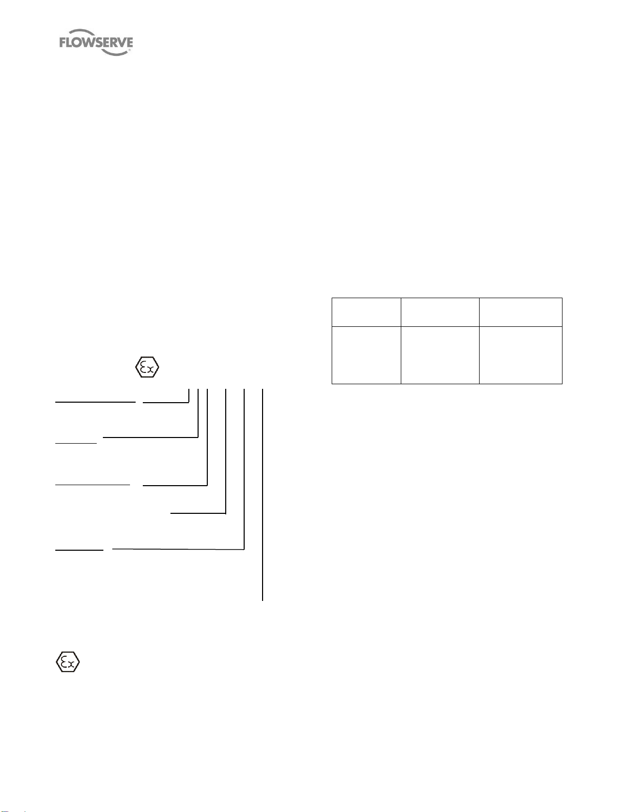
1.6.4.2 Marking
An example of ATEX equipment marking is shown
below. The actual classification of the pump will be
engraved on the nameplate.
II 2 GD c IIC 135 ºC (T4)
Equipment Group
I = Mining
II = Non-mining
Category
2 or M2 = High level protection
3 = normal level of protection
Gas and/or Dust
G = Gas; D= Dust
c = Constructional safety
(In accordance with EN13463-5)
Gas Group
IIA – Propane (typical)
IIB – Ethylene (typical)
IIC – Hydrogen (typical)
Maximum surface temperature (Temperature Class)
(See section 1.6.4.3.)
1.6.4.3 Avoiding excessive surface temperatures
ENSURE THE EQUIPMENT TEMPERATURE
CLASS IS SUITABLE FOR THE HAZARD ZONE
Pumps have a temperature class as stated in the
ATEX Ex rating on the nameplate. These are based
on a maximum ambient of 40°C (104°F); refer to
Flowserve for higher ambient temperatures.
The surface temperature on the pump is influenced
by the temperature of the liquid handled. The
maximum permissible liquid temperature depends
on the temperature class and must not exceed the
values listed in Table 1.
The temperature rise at the seals and bearings and
due to the minimum permitted flow rate is taken into
account in the temperatures stated.
The operator is responsible to ensure that the
specified maximum liquid temperature is not
exceeded.
Table 1 Maximum permitted liquid temperature
for pumps
* The table only takes the ATEX temperature class into consideration.
Pump design or material, as well as component design or material, may
further limit the maximum working temperature of the liquid.
The operator is responsible to ensure that the
specified maximum liquid temperature is not
exceeded.
Temperature classification “Tx” is used when the liquid
temperature varies and when the pump is required to
be used in differently classified potentially explosive
atmospheres. In this case the user is responsible for
ensuring that the pump surface temperature does not
exceed that permitted in its actual installed location.
If an explosive atmosphere exists during the
installation, do not attempt to check the direction of
rotation by starting the pump unfilled. Even a short
run time may give a high temperature resulting from
contact between rotating and stationary
components.
Where there is any risk of the pump being run against
a closed valve generating high liquid and casing
external surface temperatures fit an external surface
temperature protection device.
Avoid mechanical, hydraulic or electrical overload by
using motor overload trips, temperature monitor or a
Page 7 of 48 flowserve.com
Page 8

MP1 USER INSTRUCTIONS ENGLISH 26999958 – 10-12
power monitor and make routine vibration monitoring
checks.
In dirty or dusty environments, make regular checks
and remove dirt from areas around close
clearances, bearing housings and motors.
1.6.4.4 Preventing the build-up of explosive
mixtures
ENSURE THE PUMP IS PROPERLY FILLED
AND VENTED AND DOES NOT RUN DRY
Ensure the pump and relevant suction and
discharge pipeline system is totally filled with liquid
at all times during the pump operation, so that an
explosive atmosphere is prevented.
In addition it is essential to make sure that seal
chambers, auxiliary shaft seal systems and any
heating and cooling systems are properly filled.
If the operation of the system cannot avoid this
condition, fit an appropriate dry run protection device
(for example liquid detection or a power monitor).
To avoid potential hazards from fugitive emissions of
vapour or gas to atmosphere the surrounding area
must be well ventilated.
1.6.4.5 Preventing sparks
To prevent a potential hazard from mechanical
contact, the coupling guard must be non-sparking.
To avoid the potential hazard from random induced
current generating a spark, the baseplate must be
properly grounded.
Avoid electrostatic charge: do not rub non-metallic
surfaces with a dry cloth; ensure cloth is damp.
The coupling must be selected to comply with
94/9/EC and correct alignment must be maintained.
1.6.4.6 Preventing leakage
the liquid. This can occur if the pump is stationary or
running.
Bursting of liquid containing parts due to freezing
must be avoided by draining or protecting the pump
and ancillary systems.
Where there is the potential hazard of a loss of a
seal barrier fluid or external flush, the fluid must be
monitored.
If leakage of liquid to atmosphere can result in a
hazard, install a liquid detection device.
1.6.4.7 Maintenance to avoid the hazard
CORRECT MAINTENANCE IS REQUIRED
TO AVOID POTENTIAL HAZARDS WHICH GIVE A
RISK OF EXPLOSION
The responsibility for compliance with
maintenance instructions is with the plant
operator.
To avoid potential explosion hazards during
maintenance, the tools, cleaning and painting
materials used must not give rise to sparking or
adversely affect the ambient conditions. Where
there is a risk from such tools or materials,
maintenance must be conducted in a safe area.
It is recommended that a maintenance plan and
schedule is adopted. (See section 6
MAINTENANCE.)
The pump must only be used to handle liquids
for which it has been approved to have the correct
corrosion resistance.
Avoid entrapment of liquid in the pump and
associated piping due to closing of suction and
discharge valves, which could cause dangerous
excessive pressures to occur if there is heat input to
Page 8 of 48 flowserve.com
Page 9
MP1 USER INSTRUCTIONS ENGLISH 26999958 – 10-12
1.7 Nameplate and warning labels
1.7.1 Nameplate
For details of nameplate, see the Declaration of Conformity.
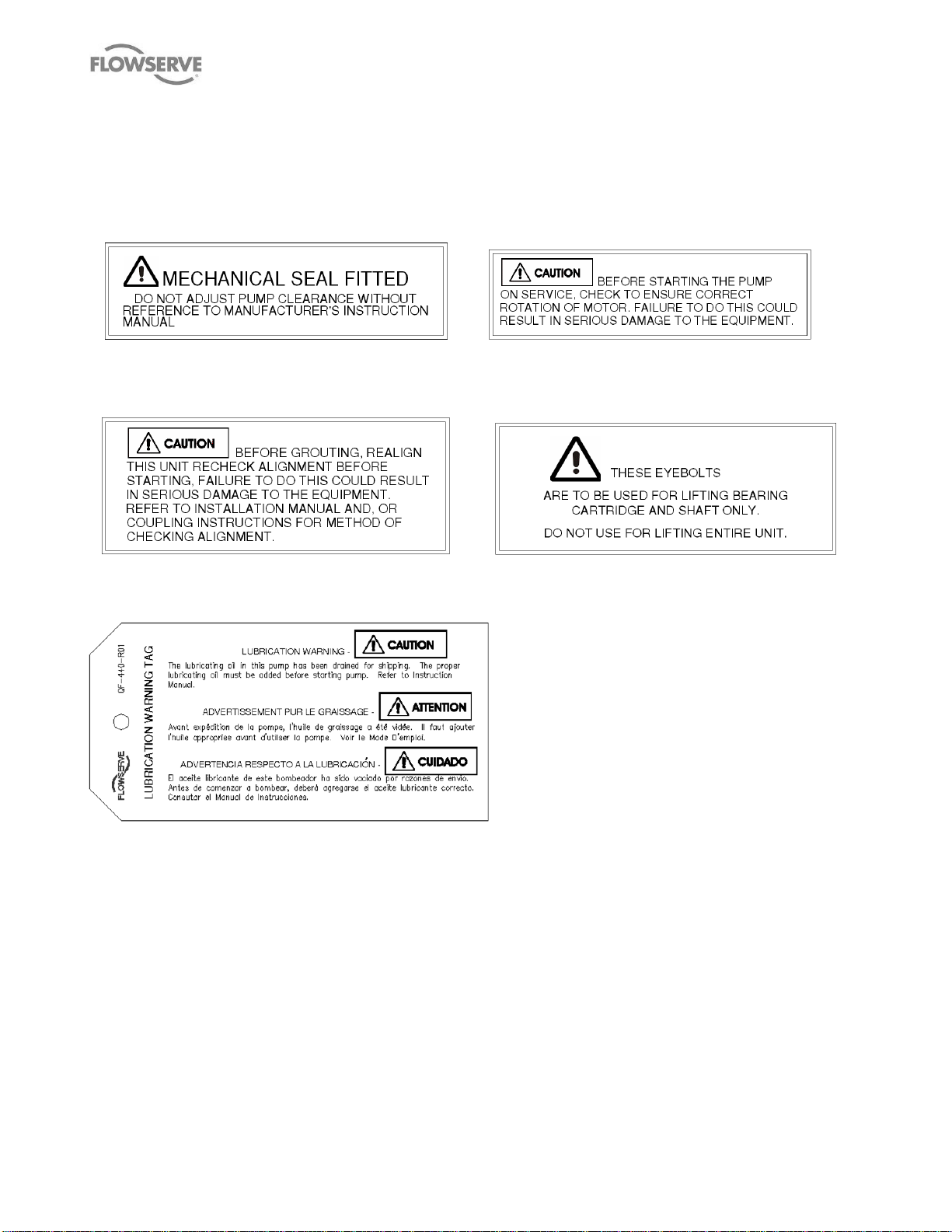
1.7.2 Safety labels
P/N 2113931-001 P/N 2113932-001
MECHANICAL SEAL WARNING ROTATION WARNING
GROUT WARNING LIFTING WARNING
P/N 2113934-001 P/N 9901701-001
LUBRICATION WARNING – QF-440-R01 (2124841)
Oil lubricated units only
Page 9 of 48 flowserve.com
Page 10

MP1 USER INSTRUCTIONS ENGLISH 26999958 – 10-12
Multiphase Twin
Screw
pump size
Sound Pressure
Level
dBA @ 1 m (3.3 ft)
Pump
Speed
rpm
MP1-150-xxx
90
1780
MP1-275-xxx
90
1780
MP1-380-xxx
90
1780
MP1-390-xxx
100
1780
1.8 Specific machine performance
For performance parameters see section 1.5 Duty
conditions. Where performance data has been
supplied separately to the purchaser these should be
obtained and retained with these User Instructions.
1.9 Noise level
Attention must be given to the exposure of personnel
to the noise, and local legislation will define when
guidance to personnel on noise limitation is required,
and when noise exposure reduction is mandatory.
This is typically 80 to 85 dBA.
The usual approach is to control the exposure time to
the noise or to enclose the machine to reduce emitted
sound. You may have already specified a limiting
noise level when the equipment was ordered, however
if no noise requirements were defined, then attention is
drawn to Table 2 to give an indication of equipment
noise level so that you can take the appropriate action
in your plant.
Pump noise level is dependent on a number of
operational factors, flow rate, pipework design and
acoustic characteristics of the building, and so the
values given are subject to a 3 dBA tolerance and
cannot be guaranteed.
Table 2 Max Sound Levels of Pumps
Similarly the motor noise assumed in the “pump and
motor” noise is that typically expected from standard
and high efficiency motors when on load directly
driving the pump. Note that a motor driven by an
inverter may show an increased noise at some
speeds.
If a pump unit only has been purchased for fitting with
your own driver then the “pump only” noise levels in
the table should be combined with the level for the
driver obtained from the supplier. Consult Flowserve
or a noise specialist if assistance is required in
combining the values.
It is recommended that where exposure approaches
the prescribed limit, then site noise measurements
should be made.
The values are in sound pressure level LpA at 1 m (3.3
ft) from the machine, for “free field conditions over a
reflecting plane”.
For estimating sound power level LWA (re 1 pW) then
add 14 dBA to the sound pressure value.
For units driven by equipment other than
electric motors or units contained within enclosures,
see the accompanying information sheets and
manuals.
Page 10 of 48 flowserve.com
Page 11
MP1 USER INSTRUCTIONS ENGLISH 26999958 – 10-12
2 TRANSPORT AND STORAGE
2.1 Consignment receipt and unpacking
Immediately after receipt of the equipment it must be
checked against the delivery/shipping documents for
its completeness and that there has been no damage
in transportation. Any shortage and/or damage must
be reported immediately to Flowserve and must be
received in writing within one month of receipt of the
equipment. Later claims cannot be accepted.
Check any crate, boxes or wrappings for any
accessories or spare parts that may be packed
separately with the equipment or attached to side walls
of the box or equipment.
Each product has a unique serial number. Check that
this number corresponds with that advised; always
quote this number in correspondence as well as when
ordering spare parts or further accessories.
2.2 Handling
Boxes, crates, pallets or cartons may be unloaded
using fork-lift vehicles or slings dependent on their size
and construction.
The pump should be lifted with suitably
sized and located slings. Do not use the shaft for lifting
and take special care to prevent the pump from rotating
in the slings due to unbalanced weight distribution. The
angle between sling or ropes used for lifting must not
exceed 60°.
2.3 Lifting
A crane must be used for all pump sets in excess
of 25 kg (55 lb). Fully trained personnel must carry out
lifting, in accordance with local regulations. The driver
and pump weights are recorded on their respective
nameplates or mass plates.
Before lifting the driver alone, refer to the
manufacturer’s instructions.
2.4 Storage
2.4.1 Short-Term Storage
When it is necessary to store a pump for a short time
before it can be installed, place it in a dry, cool
location. Protect it thoroughly from moisture and
condensation. Protective flange covers should not be
removed until the pump is being installed.
Wrap the exposed portions of the shaft and coupling to
protect against sand, grit or other foreign matter. Oil
lubricated units should be lubricated (refer to section
5.1.3 Lubrication) to protect the bearings. Grease
lubricated units are lubricated at the factory during
assembly. Turn the rotor over by hand at least once a
week to maintain a protective film on the bearing
components.
2.4.2 Long-term storage
More thorough precautions are required if long-term
storage in excess of 90 days from factory shipment is
unavoidable.
The internal surfaces of the pump should be sprayed
with a rust preventative, such as water soluble oil or
other suitable alternative. Particular attention should
be given to the integral shafts, rotors and stuffing box.
Install gasketed metal flange covers on the suction and
discharge flanges (pipe plugs in the case of tapped
connections).
A rust inhibitor should be added to the lubricating oil of
oil lubricated units to give additional protection without
destroying the lubricating properties of the oil. For
specific recommendations, consult your lubrication
dealer. Grease lubricated units, which can be identified
by the grease fitting at each bearing location, should
be well lubricated prior to placing in storage. Small
amounts of additional grease should be added at
regular intervals during storage. Refer to Section 5.1.3
Lubrication for additional information related to grease
lubrication.
Storage of pumps in areas of high ambient vibration
should be avoided to prevent bearing damage due to
false brinelling. The risk of such damage can be
reduced by frequent rotation of the shaft.
The pump half coupling and key should be removed
from the shaft, coated with rust preventative and
wrapped to prevent metal-to-metal contact. Exposed
surfaces of the pump shaft should be protected with a
rust preventative. All dismantled parts should be
wrapped and tagged according to pump serial number
and a record kept of their location.
Pumps covered with plastic should
not be stored in a cool environment because
resulting condensation can cause rusting.
Page 11 of 48 flowserve.com
Page 12

MP1 USER INSTRUCTIONS ENGLISH 26999958 – 10-12
2.5 Recycling and end of product life
At the end of the service life of the product or its parts,
the relevant materials and parts should be recycled or
disposed of, using an environmentally acceptable
method and in accordance with local regulations. If the
product contains substances that are harmful to the
environment, these should be removed and disposed
of in accordance with current local regulations. This
also includes the liquids and/or gases that may be
used in the “seal system” or other utilities.
Make sure that hazardous substances are
disposed of safely and that the correct personal
protective equipment is used. The safety
specifications must be in accordance with the current
local regulations at all times.
3 PUMP DESCRIPTION
3.1 Configurations
Flowserve Twin Screw Pumps are single stage,
positive displacement pumps especially designed for
the petroleum industries in the transfer of oils and
other liquids of varying viscosities. The flow of liquid
through the pump is accomplished by the progressive
movement of sealed cavities formed by the
intermeshing of matched pumping screws (one right
hand, one left hand) rotating in the precision ground
bores of the pump body. To balance the hydraulic
thrust created by the pumping action, two sets of
meshed screws are used, moving the liquid from both
ends of the body to the discharge port located at the
center of the body.
The key assembly of the screw pump is the rotating
element. Each rotating element consists of a drive
shaft and a driven shaft running on parallel axes at a
fixed center distance. Each shaft holds bearings, one
timing gear and two opposing pumping screws plus the
assorted hardware (lock nuts, spacers) required for
mounting. With integral design, the pumping screws
and the shaft are an integral piece machined from a
single steel bar. Precise clearances are maintained
between meshing screws to limit the internal leakage
(slip) in the pump. The timing gears maintain these
clearances, prevent contact between the pumping
screws and turn the driven shaft. Heavy duty roller
bearings eliminate radial contact between the pumping
screws and the body bores and support the loading on
the shafts produced by the pumping action. Ball
bearings position the shafts axially and prevent contact
between the flanks (sides) of the meshing screws.
Generally lubrication of the bearings is provided by oil
contained in housings (sumps).
The rear timing gear configuration provides a rear pullout feature which permits the quick removal of the
entire rotating element without disturbing the pump
body or the drive. (Refer to Section 6.8 Disassembly).
The use of a spacer type coupling between the pump
and driver is necessary to apply this feature.
Shaft sealing is typically provided and installed by
factory. Mechanical seals require no adjustment prior
to or during pump operation.
All pumps are shop performance tested to ensure
mechanical reliability and compliance with the
specified conditions of service. They are carefully
inspected and prepared for shipment. All exterior
machined surfaces are coated with rust preventative
and all openings are provided with covers or plugs.
3.2 Name structure
The pump size will be engraved on the nameplate. The
following example explains how the pump name
identifies the construction features
MP1-275-355
MP indicates pump is for multiphase application
275 indicates screws OD in mm
355 indicates bore length in mm
3.3 Design of major parts
3.3.1 Pump casing
The pump casing is a casting with side suction and top
discharge connections, or both connections on top.
Refer to the Outline or General Arrangement drawings
for further details. It is a two pieces (Outer Casing and
Inner Casing or also typically named Liner) pressure
retaining casting assembly, with gasket connections
between the Outer and Inner Casing, as well as to the
seal housings and the suction and discharge flanges.
3.3.2 Pumping Rotors
The pumping rotors (screws) are single start and
mounted to a shaft in opposing configuration i.e. one
left and one right hand rotor to each shaft. The
intermeshing screws integral part of drive and driven
shafts create a positive displacement pumping action
inside the pump body.
Page 12 of 48 flowserve.com
Page 13

MP1 USER INSTRUCTIONS ENGLISH 26999958 – 10-12
Pumped liquid temperature limits
up to +177 ºC (300 ºF)
Maximum ambient temperature
up to +50 ºC (122 ºF)
Maximum soft solids in suspension
up to 1% by volume
Maximum pump speed
Refer to the nameplate
3.3.3 Shaft
The drive shaft is mounted on bearings with the
pumping rotor and timing gear mounted to the shaft. It
has a keyed drive end. The driven shaft is also
mounted on bearings with the pumping rotor and
timing gear mounted to the shaft.
3.3.4 Timing Gears
The timing gears are mounted to the drive and driven
shafts with accurately located keys to maintain the
pumping rotors in mesh with no contact with each
other.
3.3.5 Pump bearings and lubrication
Antifriction radial and thrust bearings are mounted on
each shaft to support the induced loads. An external
lube oil system and/or an oil bath might be provided at
each end of the pump to lubricate the bearings and
timing gears. An oil site gage might be supplied in the
bearing housings.
Certain multiphase applications may require a
separate lubrication and lube oil cooling system
depending on the condition of service.
3.3.6 Stuffing box/seal housing
The stuffing box housing is doweled to both the pump
casing and the bearing housing to ensure proper
alignment. It is supplied to fit appropriate mechanical
seals.
3.3.7 Shaft seal
The mechanical seals, attached to the pump shaft,
seal the pumped liquid from the environment.
3.3.8 Driver
The driver is normally an electric motor. Different drive
configurations may be fitted such as internal
combustion engines, turbines, hydraulic motors etc.
driving via couplings, belts, gearboxes etc.
3.3.9 Accessories
Accessories may be fitted when specified by the
customer.
3.4 Performance and operating limits
This product has been selected to meet the
specifications of your purchase order (See section 1.5
Duty conditions). The following data is included as
additional information to help with your installation. It
is typical, and factors such as temperature, materials,
and seal type may influence this data. If required, a
definitive statement for your particular application can
be obtained from Flowserve.
3.4.1 Operating limits
3.4.2 Speed torque curves
To bring a rotary pump up to rated speed, the driver
must be capable of providing more torque at each
speed than required by the pump. Normally, this is not
a problem with standard induction or synchronous
motors, provided the proper voltage is supplied at the
motor.
The margin between the available and required torque
affects the time it takes the unit to reach full speed. If
the torque required by the pump exceeds the torque
capability of the drive at any run-up speed, the unit will
not accelerate to full speed.
For pumps started at set system resistance conditions,
100 % full speed torque can be calculated by using the
formula:
Torque (Nm) = 9545 Power (kW)
RPM
Torque (lbf · ft) = 5250 Power (hp)
RPM
Torque required by the pump at any other speed
during start-up can be determined from the curve
above. Note that the driver manufacturer usually
bases 100 % torque on the design power of the driver
and consequently the speed-torque curves should be
plotted in torque units (e.g. Nm or lbf · ft) instead of
percentage torque to avoid confusion.
Page 13 of 48 flowserve.com
Page 14
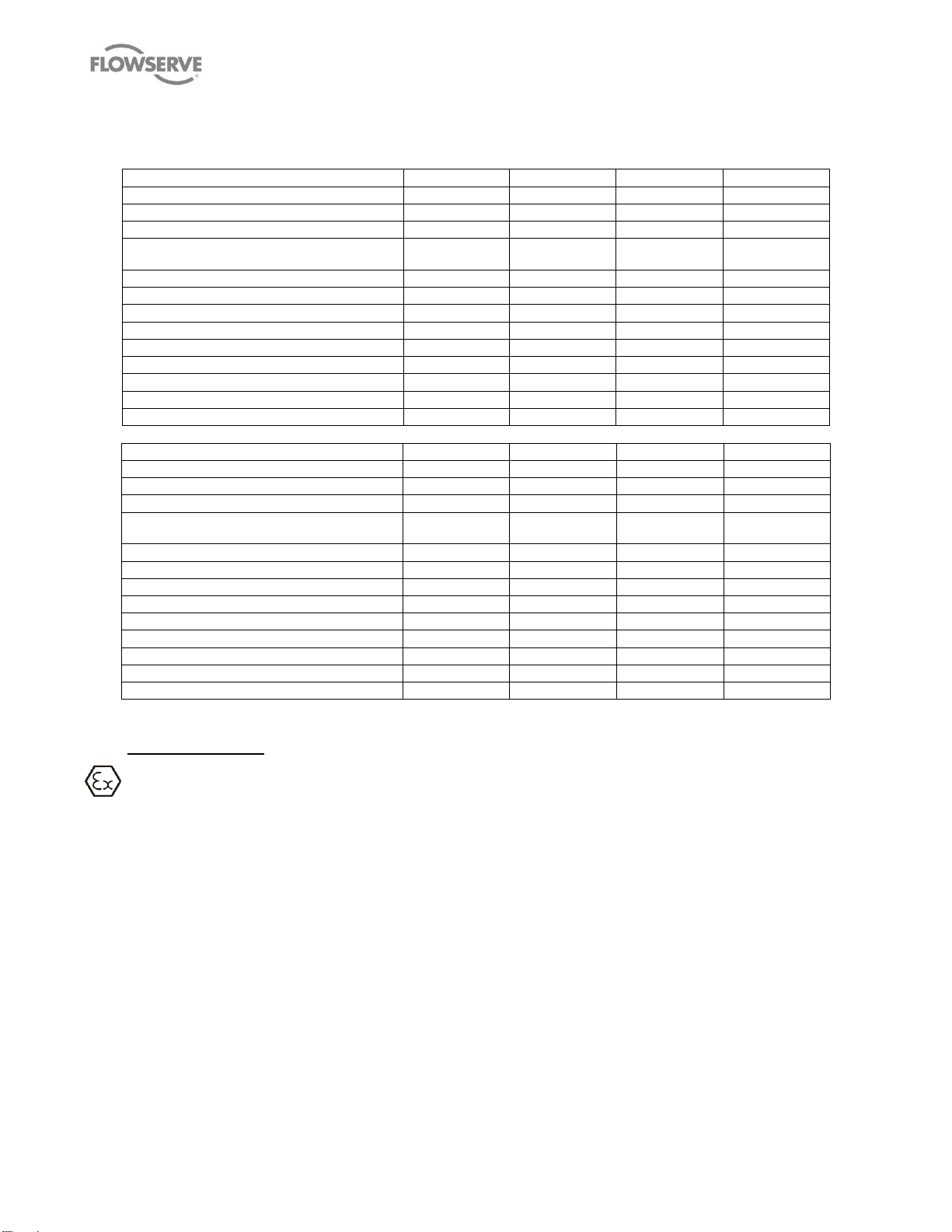
3.5 Table of Engineering Data (Table 3)
PUMP SIZE
MP1-150-200
MP1-275-255
MP1-275-355
MP1-380-305
SHAFT/SCREW DESIGN
INTEGRAL
INTEGRAL
INTEGRAL
INTEGRAL
STD SUCTION SIZE
6 in.- 600#
10 in.- 300#
10 in. - 300#
10 in. - 300#
STD DISCHARGE SIZE
4 in. - 600#
110 in. - 300#
10 in. - 300#
10 in. - 300#
STD OD CLEARANCE mm (in.)
0.30/0.45
(0.012/0.018)
0.51/0.76
(0.020/0.030)
0.51/0.76
(0.020/0.030)
0.51/0.76
(0.020/0.030)
APPROX PUMP WEIGHT kg (lb.)
658 (1450)
4490 (9900)
5900 (12990)
6591 (14500)
ROT ELEMENT WEIGHT kg (lb.)
136 (300)
508 (1120)
670 (1470)
990 (2175)
MOMENT OF INERTIA kgm^2 (lb·in2)
0.250 (855)
3.670 (12 540)
3.670 (12 540)
2.356 (8050)
SHAFT DIAMETER @ COUPLING mm (in.)
53.98 (2.125)
92.08 (3.625)
92.08 (3.625)
92.08 (3.625)
SHAFT TAPER @ COUPLING mm/m (in/ft.)
60 (¾)
40 (½)
40 (½)
40 (½)
SHAFT DIAMETER @ ST BOX mm (in.)
73.0 (2.875)
130.2 (5.125)
130.2 (5.125)
130.2 (5.125)
NO OF SEALING CHAMBERS
4 4 4
4
OIL FILL TIMING GEAR HSG liters (qt.)
3.0 (3.2)
21 (22.2)
21 (22.2)
3.4 (3.6)
OIL FILL BEARING HSG liters (qt.)
0.25 (0.26)
8.5 (9.0)
8.5 (9.0)
1.5 (1.6)
PUMP SIZE
MP1-390-305
MP1-380-355
MP1-390-610
MP1-390-406
SHAFT/SCREW DESIGN
INTEGRAL
INTEGRAL
INTEGRAL
INTEGRAL
STD SUCTION SIZE
10 in. - 1500#
10 in. - 300#
16 in. - 300#
16 in. - 600#
STD DISCHARGE SIZE
8 in. - 1500#
10 in. - 300#
16 in. - 300#
16 in. - 600#
STD OD CLEARANCE mm (in.)
0.51/0.76
(0.020/0.030)
0.51/0.76
(0.020/0.030)
0.76/0.89
(0.030/0.035)
0.76/0.89
(0.030/0.035)
APPROX PUMP WEIGHT kg (lb.)
8300 (18 300)
6804 (15 000)
10 500 (23 148)
10 560 (23 280)
ROT ELEMENT WEIGHT kg (lb.)
975 (2150)
1157(2550)
1009(4583)
7612 (3460)
MOMENT OF INERTIA kgm^2 (lbs·in2)
12.759 (43 600)
14.354 (49 050)
25.433 (86 909)
18.041 (61 650)
SHAFT DIAMETER @ COUPLING mm (in.)
92.08 (3.625)
92.08 (3.625)
111.13 (4.375)
111.13 (4.375)
SHAFT TAPER @ COUPLING mm/m (in/ft.)
40 (½)
60 (¾)
40 (1/2)
40 (½)
SHAFT DIAMETER @ ST BOX mm (in.)
130.2 (5.125)
130.2 (5.125)
209.5 (8.25)
209.5 (8.25)
NO OF SEALING CHAMBERS
4 4 4
4
OIL FILL TIMING GEAR HSG liters (qt.)
3.4 (3.6)
3.4 (3.6)
3.4 (3.6)
3.4 (3.6)
OIL FILL BEARING HSG liters (qt.)
1.5 (1.6)
1.5 (1.6)
1.5 (1.6)
1.5 (1.6)
Table 3 Engineering data
MP1 USER INSTRUCTIONS ENGLISH 26999958 – 10-12
4 INSTALLATION
Equipment operated in hazardous locations
must comply with the relevant explosion protection
regulations. See section 1.6.4 Products used in
potentially explosive atmospheres.
The recommended order of operations to install a
pump skid is as follows:
a) Construct Foundation (Section 4.3)
b) Install Baseplate (Section 4.4)
c) Initial Alignment (Section 4.5)
d) Grouting (Section 4.6)
e) Fabrication and Installation of Piping (Section 4.7)
f) Final Shaft Alignment (Section 4.9)
g) Electrical Connections (Section 4.10)
h) Commissioning (Section 5.0)
4.1 Location
The pump should be located to allow room for access,
ventilation, maintenance and inspection and should be
as close as practicable to the supply of liquid to be
pumped. There should be ample room to allow the use
of an overhead crane or lifting device with sufficient
capacity to lift the heaviest part of the unit. Simple
suction and discharge piping layouts are desired.
Allow sufficient room to facilitate the back pull-out
feature.
Refer to the general arrangement drawing for the
pump set.
4.2 Part assemblies
Motors may be supplied loose on Twin Screw pumps,
typically on frame sizes 400 and above. It is the
responsibility of the installer to ensure that the motor is
Page 14 of 48 flowserve.com
Page 15
MP1 USER INSTRUCTIONS ENGLISH 26999958 – 10-12
assembled to the pump and lined up as detailed in
section 4.5.2 Alignment method.
4.3 Foundation
The foundation may consist of any
material that will afford permanent, rigid support to the
full area of the pump or driver supporting member. It
should be of sufficient size and mass to absorb
expected strains and shocks that may be encountered
in service. Concrete foundations built on solid ground
are desirable.
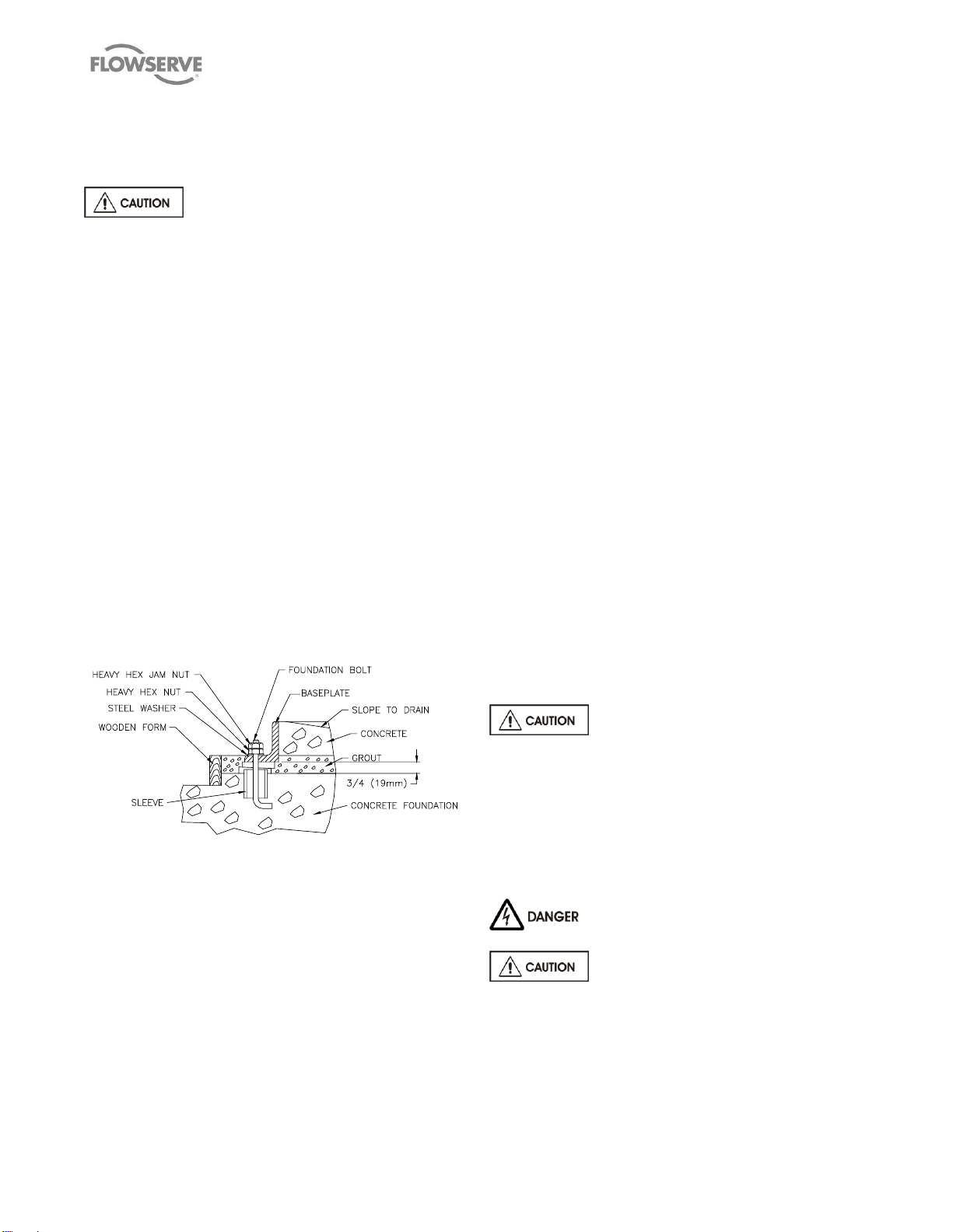
The purpose of foundation bolts is to anchor the pump
unit securely to the foundation such that the foundation
and pump assembly become a single structural unit.
High strength steel foundation bolts (SAE Gr. 5 or
better) of the specified diameter should be located
according to the elevation drawing provided. Each bolt
should be surrounded by a pipe sleeve two or three
times the diameter of the bolt (see Figure 1). The
sleeves should be securely anchored and designed to
allow the bolts to be adjusted to conform to the holes
in the baseplate. The bolts should be sufficiently long
to allow for wedges or shims or levelling nuts under the
baseplate, and a washer, heavy hex nut and hex jam
nut for retention. Since baseplate levelling is
performed after the foundation has cured, it is best to
use extra-long bolts which can be shortened after the
installation is complete.
Remove the flange covers and check inside the pump
nozzles for cleanliness. Kerosene is recommended as
the best solvent for removing factory applied rust
preventative. Ensure that all traces of rust preventative
are removed from the discharge and suction flange
faces, the exposed shafting and all coupling surfaces.
Flush the pump internals of any rust preventative
applied for long term storage.
Lift the baseplate assembly, remove the shipping skids
and clean the underside of the baseplate. Position the
baseplate over the foundation and lower the unit over
the foundation bolts and onto the wedges, shims or
jacking nuts.
With the aid of a machinist's level, adjust the wedges,
shims or jacking nuts to level the pump and driver
mounting pads in each direction. Check to ensure that
the suction and discharge flanges are plumb, level,
and at the correct elevation. It is normal practice to set
the mounting pads slightly low in order to permit
lowering of units which may be required to suit future
piping or minor changes. Place washers over the
foundation bolts and install nuts. Tighten finger tight
only. Check that the rotor turns freely by hand.
Note: Grout shall not be poured until an initial
preliminary alignment of the pump and driver has
been performed.
4.5 Initial alignment
4.5.1 Thermal expansion
The pump and motor will normally have
to be aligned at ambient temperature and should be
corrected to allow for thermal expansion at operating
temperature. In pump installations involving high liquid
temperatures, the unit should be run at the actual
operating temperature, shut down and the alignment
re-checked and re-adjusted as deemed necessary
Figure 1 – Grout Installation
4.4 Baseplate installation
Position the baseplate and pump next to the
foundation and clean the foundation surface
thoroughly. Remove the rag packing from the pipe
sleeves and place wedges or shims as close to the
foundation bolts as possible. These may be omitted if
a jacking nut on the foundation anchor bolts is
preferred for levelling. Initial levelling should be within
0.75 mm (0.030 in.).
Page 15 of 48 flowserve.com
immediately.
4.5.2 Alignment methods
Ensure pump and driver are isolated
electrically and the half couplings are disconnected.
The alignment MUST be checked.
Although the pump will have been aligned at the
factory it is most likely that this alignment will have
been disturbed during transportation or handling. If
necessary, align the motor to the pump, not the pump
to the motor.
Page 16

Figure 2 – Parallel and angular misalignment
The importance of accurate alignment of pump and
driver shafts cannot be overemphasized.
IMPROPER ALIGNMENT IS THE PRIMARY CAUSE
OF VIBRATION PROBLEMS AND REDUCED
BEARING LIFE.
A flexible coupling is used to compensate for slight
changes in alignment which occur during normal
operation and is not used to correct for installation
errors. Install the pump and driver half couplings in
accordance with the coupling manufacturer's
instructions. Note that the coupling hub faces are not
always mounted flush with the ends of the shafts.
Place the driver on the baseplate such that the correct
spacing is obtained between the two half couplings.
CHECK IF THERE IS A NEED TO SET
THE ELECTRIC MOTOR MAGNETIC CENTER AND
THE AXIAL ALIGNMENT BEFORE PROCEEDING
WITH ANY PARALLEL AND ANGULAR
ALIGNMENT. FAILURE TO DO SO MIGHT POSE
SERIOUS RISKS TO THE RELIABLE OPERATION
OF THE PUMP.
In the case of high power electric motors having sleeve
bearings, it might be necessary to run the motor to
establish the rotor magnetic center before defining the
axial setup of the pump. Consult the manufacturer's
instruction manual of the motor for additional details.
The purpose of the alignment procedure is to ensure
that there is no axial hunt/thrust nor eccentricity that
might create unbalance, between the driver shaft
(electric motor, gearbox, hydraulic power transmitter,
vapour/gas turbine, engine, etc.) and the pump shaft
that might affect or jeopardize the coupling mechanical
performance, and that both shafts are in parallel and
MP1 USER INSTRUCTIONS ENGLISH 26999958 – 10-12
angular alignment under the normal operating
conditions of load and temperature (See Figure 2).
When the pump coupling and driver are assembled at
the factory, the units are aligned prior to shipment.
However, baseplates can be sprung or distorted during
shipment or installation and the alignment must be
checked before the unit is put in service. The coupling
spacer must be removed to make this check.
For pumps and drivers which operate at different
temperatures compensation must be made at the initial
alignment stage (when the units are at the same
temperature) to allow for thermal expansion during
operation. Consult the instruction manual supplied with
the driver for the manufacturer's recommendations.
Shaft alignment is greatly simplified by the use of a dial
indicator with extension rods and a magnetic base, or
using laser alignment devices. Before taking readings,
ensure that the pump and driver mounting bolts are
secure, and that the thrust bearing housing is properly
aligned in the bearing frame or cartridge. (See Section
6 MAINTENANCE).
Parallel Alignment:
Mount the magnetic base on the pump half coupling
hub (either the face or the O/D as shown in the sketch)
and place the dial indicator button on the outside
diameter of the driver half coupling hub. (See Figure
3).
Note that the length of extension rods should be kept
at a minimum to reduce deflection. Rotate the pump
shaft and record the dial reading at the top, bottom and
each side. Correct the parallel alignment by adding or
removing shims under the driver and/or moving the
driver horizontally.
Figure 3 – Parallel Misalignment
Repeat this procedure until the maximum Total
Indicator Reading (T.I.R.) is within 0.076 mm (0.003
in.).
Page 16 of 48 flowserve.com
Page 17

Angular Alignment:
With the magnetic base mounted on the pump half
coupling hub, move the dial indicator button to indicate
on the face of the driver half coupling hub as close to
the outside diameter as possible. (See Figure 4). Turn
both shafts 360 and record the dial readings at 90
intervals. Adjust the shims under the motor as required
and repeat the procedure until the angular alignment is
within 0.0005 mm (T.I.R.) per mm (0.0005 in. per in.)
of maximum hub diameter.
MP1 USER INSTRUCTIONS ENGLISH 26999958 – 10-12
If the motor does not run in its magnetic
centre the resultant additional axial force may overload
the pump thrust bearing.
4.5.3 Check for soft foot
Figure 4 – Angular Misalignment
Repeat the checks on parallel and angular alignment,
ensuring the mounting bolts are secure, until the unit is
properly aligned. Note that correction in one direction
may affect the alignment in another direction. Recheck the gap between the coupling hubs.
If any difficulty is encountered in achieving the
recommended alignment tolerances, the run out of the
pump and driver shafts and each coupling hub
diameter and face should be checked. Occasionally,
due to practical and unavoidable manufacturing
tolerance build-up associate with the pump, coupling
and driver, it may be necessary to match up the two
coupling hubs in the most advantageous relative
angular position in order to achieve an acceptable
alignment.
Do not install the coupling spacer or sleeve until
grouting is complete and cured and the alignment is
re-checked.
When the electric motor has sleeve bearings it is
necessary to ensure that the motor is aligned to run on
its magnetic centreline. A button (screwed into one of
the shaft ends) is normally fitted between the motor
and pump shaft ends to fix the axial position.
Figure 5 – Check for soft foot
This is a check to ensure that there is no undue stress
on the driver holding down bolts; due to non-level
baseplate or twisting. To check, remove all shims and
clean surfaces and tighten down driver to the
baseplate. Set a dial indicator as shown in Figure 5
and loosen off the holding down bolt while noting any
deflection reading on the dial test Indicator - a
maximum of 0.05 mm (0.002 in.) is considered
acceptable but any more will have to be corrected by
adding shims. For example, if the dial test indicator
shows the foot lifting 0.15 mm (0.006 in.) then this is
the thickness of shim to be placed under that foot.
Tighten down and repeat the same procedure on all
other feet until all are within tolerance.
Complete piping as below and see sections 4.9
Final shaft alignment check up to and including section
5 COMMISSIONING, START-UP, OPERATION AND
SHUTDOWN before connecting driver and checking
actual rotation.
4.6 Grouting
The purpose of grouting is to provide rigid support to
the pump and driver by increasing the structural rigidity
of the baseplate and making it an integral mass with
the foundation.
Clean the roughed foundation surface and build a
wooden form around the baseplate (see Figure 1). For
initial grouting forms should be placed to isolate shims
and levelling nuts. The foundation surface should be
thoroughly saturated with water before grouting. A
typical mixture for grouting-in a pump base is
composed of one part pure Portland cement and two
Page 17 of 48 flowserve.com
Page 18

parts of clean building sand with sufficient water to
provide the proper consistency. The grout should flow
freely but not be so wet as to cause the sand and
cement to separate.
Thoroughly puddle the grout while pouring to eliminate
air pockets and low spots. Pour sufficient grouting to
ensure that the bottom surface of the baseplate is
completely submerged. Do not fill isolated areas
around the shims or levelling nuts. Once the grout has
set sufficiently, remove the wooden forms and finish off
the sides and top as desired. At the same time,
roughen the grout surface inside the baseplate. Cover
with wet burlap and allow the grout to cure for at least
40 hours.
After grouting has cured, shims and levelling nuts
should be removed or backed off. Tighten down
baseplate to the new grout to put bolts in tension and
ensure rigidity of structure. Install jam nuts and cut the
bolts to the desired length. Finish grouting isolated
areas. Fill the baseplate including pump and driver
support pedestals with concrete. Trowel and slope the
surface to give suitable drainage.
After the concrete has cured, and while the pump and
driver are uncoupled, the driver rotation should be
checked. Be sure that the driver is locked out after this
check. Note that the required pump shaft rotation is
marked on the front head of the pump (see section
5.3 Direction of rotation)
4.7 Piping
MP1 USER INSTRUCTIONS ENGLISH 26999958 – 10-12
Excessive pipe loads and/or soft feet
will cause serious damage to the pump. Verify both
before pump is started.
Maximum forces and moments allowed on the pump
flanges vary with the pump size and type. To minimize
these forces and moments that may, if excessive,
cause misalignment, hot bearings, worn couplings,
vibration and the possible failure of the pump casing,
the following points should be strictly followed:
Prevent excessive external pipe load
Never draw piping into place by applying force to
pump flange connections
Do not mount expansion joints so that their force,
due to internal pressure, acts on the pump flange
Information regarding maximum allowable forces and
moments on the suction and discharge flanges is
provided on the General Arrangement drawing.
Suction and discharge piping and associated
equipment should be supported and anchored near to
but independent of the pump. If an expansion joint or
non-rigid coupling must be used, a pipe anchor must
be installed between it and the pump to ensure that
any flange loads do not exceed the specified limits.
If operational difficulties are encountered, suction and
discharge pressure readings must be determined to
establish the cause of the problem. In anticipation of
such problems, pressure taps, located in a straight
section of pipe between the pump and first fitting
should be provided on the suction and discharge lines.
Protective covers are fitted to the pipe
connections to prevent foreign bodies entering during
transportation and installation. Ensure that these
covers are removed from the pump before connecting
any pipes.
4.7.1 Suction and discharge pipework
In order to minimize friction losses and hydraulic noise
in the pipework it is good practice to choose pipework
that is one or two sizes larger than the pump suction
and discharge. Typically main pipework velocities
should not exceed 2 m/s (6 ft/sec) suction and 3 m/s (9
ft/sec) on the discharge.
Take into account the available NPSH which must be
higher than the required NPSH of the pump.
Never use the pump as a support for
piping.
Page 18 of 48 flowserve.com
before use.
Ensure piping for hazardous liquids is arranged
to allow pump flushing before removal of the pump.
4.7.2 Suction piping
a) The suction piping should be as short and as
direct as possible.
b) The inlet pipe should be one or two sizes larger
than the pump inlet bore and pipe bends should be
as large a radius as possible.
c) Pipework reducers should have a maximum total
angle of divergence of 15 degrees.
d) On suction lift the piping should be inclined up
towards the pump inlet with eccentric reducers
incorporated to prevent air locks.
e) On positive suction, the inlet piping must have a
constant fall towards the pump.
f) Flow should enter the pump suction with uniform
flow, to minimize noise and wear. This is
Ensure piping and fittings are flushed
Page 19

MP1 USER INSTRUCTIONS ENGLISH 26999958 – 10-12
particularly important on large or high-speed
pumps which should have a minimum of two
diameters of straight pipe on the pump suction
between the elbow and inlet flange. See section
10.3 Additional sources of information for more
detailed technical explanations on this piping
design requirement.
g) Inlet strainers, when used, should have a net `free
area' of at least three times the inlet pipe area.
h) Fitting an isolation valve will allow easier
maintenance.
i) Never throttle pump on suction side.
4.7.3 Discharge piping
A non-return valve should be located in the discharge
pipework to protect the pump from excessive back
pressure and hence reverse rotation when the unit is
stopped.
Pipework reducers should have a maximum total angle
of divergence of 15 degrees. Fitting an isolation valve
will allow easier maintenance.
4.7.4 Relief Valves
Twin Screw Pumps are of the positive
displacement type; considerable pressure will develop
in the discharge piping and inside of the pump if
discharge line is blocked through closing of valve, etc.
It is therefore necessary for the protection of the pump
and discharge line to provide a relief valve. This should
be piped back to the suction tank and not to the
suction line.
4.7.5 Auxiliary piping
4.7.5.1 Drains
Pipe pump casing drains to a convenient disposal
point, according to the appropriate safety, health and
environment policies of the location for the pump’s
application.
4.7.5.2 Mechanical seals
Single seals requiring re-circulation will normally be
provided with the auxiliary piping from pump casing
already fitted.
If the seal requires an auxiliary quench then a
connection must be made to a suitable source of liquid
flow, low pressure steam or static pressure from a
header tank. Recommended pressure is 0.35 bar
(5 psi) or less. Check section 8.2 General arrangement
drawing.
Special seals may require different auxiliary piping to
that described above. Consult separate User
Instructions and/or Flowserve if unsure of correct
method or arrangement.
For pumping hot liquids, to avoid seal damage, it is
recommended that any external flush/cooling supply
be continued after stopping the pump.
4.7.6 Final checks
Check the tightness of all bolts in the suction and
discharge pipework. Check also the tightness of all
foundation bolts.
4.8 Pressure gauges
It is recommended that suitable suction and discharge
pressure gauges be provided. Pressure readings are
essential to resolving operational problems and are
useful for monitoring pump performance.
4.9 Final shaft alignment check
After connecting piping to the pump, rotate the shaft
several times by hand to ensure there is no binding
and all parts are free.
Recheck the coupling alignment, as previously
described, to ensure no pipe strain. If pipe strain
exists, correct piping.
4.10 Electrical connections
Electrical connections must be made by
a qualified Electrician in accordance with relevant local
national and international regulations.
It is important to be aware of the EUROPEAN
DIRECTIVE on potentially explosive areas where
compliance with IEC60079-14 is an additional
requirement for making electrical connections.
It is important to be aware of the EUROPEAN
DIRECTIVE on electromagnetic compatibility when
wiring up and installing equipment on site. Attention
must be paid to ensure that the techniques used
during wiring/installation do not increase
electromagnetic emissions or decrease the
electromagnetic immunity of the equipment, wiring or
any connected devices. If there is any doubt contact
Flowserve for advice.
The motor must be wired up in
accordance with the motor manufacturer's instructions
(normally supplied within the terminal box) including
any temperature, earth leakage, current and other
protective devices as appropriate. The identification
Page 19 of 48 flowserve.com
Page 20

MP1 USER INSTRUCTIONS ENGLISH 26999958 – 10-12
nameplate should be checked to ensure the power
supply is appropriate.
A device to provide emergency stopping must be
fitted.
If not supplied pre-wired to the pump unit, the
controller/starter electrical details will also be supplied
within the controller/starter.
For electrical details on pump sets with controllers see
the separate wiring diagram.
See section
5.3 Direction of rotation before connecting the motor to
the electrical supply.
4.11 Protection systems
The following protection systems are
recommended particularly if the pump is installed in a
potentially explosive area or is handling a hazardous
liquid. If in doubt consult Flowserve.
If there is any possibility of the system allowing the
pump to run against a closed valve or below minimum
continuous safe flow a protection device should be
installed to ensure the temperature of the liquid does
not rise to an unsafe level.
If there are any circumstances in which the system can
allow the pump to run dry, or start up empty, a power
monitor should be fitted to stop the pump or prevent it
from being started. This is particularly relevant if the
pump is handling a flammable liquid.
If leakage of product from the pump or its associated
sealing system can cause a hazard it is recommended
that an appropriate leakage detection system is
installed.
To prevent excessive surface temperatures at bearings
it is recommended that temperature or vibration
monitoring are carried out. See sections 5.9.3
Bearings and 5.9.4 Normal vibration levels, alarm and
trip.
The user should review the need for special operating
procedures and protective devices peculiar to the
particular installation involved. These may include
special start-up and shut-down procedures, over-
speed protection, temperature, flow and pressure
interlocks, protection against automatic start-up in the
event of power failure, surge protection, protection
from freezing, lack of prime protection, temporary
strainers in the suction line, vacuum breakers, etc.
Great care should be exercised during the erection of
piping to keep lines clean and free of dirt, scale,
threading or welding chips, etc. Such foreign matter
entering the pump may cause scoring of the body
bores and unnecessary breakdown and costly repairs.
For pumps having jacketed bodies, the jacket inlet
piping should always be made at the lowest inlet point
with the outlet at the top or highest point and the
opposite configuration when using a gaseous heat
transfer media. Provide a valve on the inlet piping so
that flow may be regulated to control temperature.
5 COMMISSIONING, START-UP,
OPERATION AND SHUTDOWN
These operations must be carried
out by fully qualified personnel.
5.1 Pre-commissioning procedure
5.1.1 Check-list
To avoid operational difficulties and to ensure a trouble
free initial start-up, the following additional checks
should be made.
1. Check that all piping has been properly bolted,
anchored and braced. If the system is
hydrostatically tested, ensure that the pump and
other equipment is properly vented and
adequately protected against excessive pressure.
(See Sections 4.11 Protection systems and 5.9.1
Venting the pump.)
2. Flush the piping system, particularly the suction
line, to ensure that all foreign material has been
removed.
3. Check that all valves and automatic equipment are
operating properly.
4. Ensure that drivers are provided with properly set
over-load and/or over speed protection devices as
required.
5. Check all auxiliary piping circuits.
5.1.2 Freezing
Precautions should be taken to prevent the liquid in the
pump or associated piping from freezing.
5.1.3 Lubrication
In general, bearing lubrication is provided by
lubricating oil contained in housings located at both
ends of the pump.
Fill the bearing housings with the
correct grade of oil to the correct level, i.e. sight glass
Page 20 of 48 flowserve.com
Page 21

MP1 USER INSTRUCTIONS ENGLISH 26999958 – 10-12
Company
Column “A”
Column “B”
Column “C”
Mobil
Mobil DTE Oil BB
MOBILGEAR 626
Mobil DTE Oil HH
Shell
OMALA Oil 220
OMALA Oil 68
OMALA Oil 460
Sunoco
SUNVIS 790 (220)
SUNVIS 747 (46)
SUNVIS 7150
Amoco
RYKON Oil No. 220
AMOGEAR No. 68
American Industrial Oil No. 460
Texaco
REGAL R&O 220
MEROPA 150
REGAL R&O 460
Arco
PENNANT NL 220
PENNANT NL 68
RUBILENE 460
Chevron
AW Machine Oil 220
EP Industrial Oil 46x
NL Gear Compound 460
Exxon
TERESSTIC N220
SPARTAN EP 68
TERESSTIC 460
*Esso
TERESSO N220
SPARTAN EP 68
CYLESSO TK 460
TERESSO 100 - -
BP
ENERGOL HL 100 - -
Petro Canada
GIREX 220
GIREX 68
GIREX 320
or constant level oiler bottle or the level mentioned on
sectional drawing.
When fitted with a constant level oiler, the bearing
housing should be filled by unscrewing or hinging back
the transparent bottle and filling the bottle with oil.
Where an adjustable body Trico oiler is fitted this
should be set to the proper height.
5.2 Lubricants
5.2.1 Typical oils
Table 4 – Typical lubricating oils
The oil filled bottle should then be refitted so as to
return it to the upright position. Filling should be
repeated until oil remains visible within the bottle.
Other drivers and gearboxes, if appropriate, should be
lubricated in accordance with their manuals.
In case of separate shaft mounted lube oil circulating
pump, refer to general arrangement drawing for
instructions
*Imperial Oil Limited (Canada)
5.2.2 Lubrication schedule
5.2.2.1 Requirements for oil lubricated bearings
Normal oil change intervals are 2500 operating hours or
at least every 6 months whichever occurs first,
depending on the temperature of the service, the
service conditions, and quality of the lubricant regarding
oxidation stability capability. For pumps on hot service
or in severely damp or corrosive atmosphere, the oil will
require changing more frequently. Lubricant analysis
(change in appearance, odour, viscosity, oxidation,
water/contaminants concentration, etc.), as well as
bearing temperature analysis, can be useful in
optimizing lubricant change intervals.
The lubricating oil should be a high quality mineral oil
having foam inhibitors. Synthetic oils may also be used
if checks show that the rubber oil seals will not be
adversely affected.
The bearing temperature may be allowed to rise to
50 ºC (90 ºF) above ambient, but should not exceed
82 ºC (180 ºF). An abrupt or continuously rising
temperature may be indicating a fault.
Oils used in the bearing housing should meet the
following requirements:
1. Oxidation Stability Specification per AGMA
Standard 250.04 table 1, page 9.
2. Foam Suppression Specification per AGMA
Standard 250.04 table 1, page 9.
At initial start-up, oil must be drained completely and
replaced after one week or 100 hours running time
(except for temperatures above 121 C (250 F)), or
even earlier, after 50 hours running time.
An analysis of the expected operating temperatures
should be conducted to determine the proper oil that
should be used in the pump. It should be noted in the
case of a large swing in ambient temperatures, it may
require different types of oils are used for summer and
winter. Unless otherwise noted by Flowserve
engineering, the following information should be used
to determine the proper oil to use in the pump and
whether more than one type of oil may be required
during yearly operation.
Page 21 of 48 flowserve.com
Page 22

MP1 USER INSTRUCTIONS ENGLISH 26999958 – 10-12
Recommended oils are:
For normal running temperatures between 10 and
65 C (50 and 150 F):
Indoor installations or outdoor summer conditions with
ambient temperature of –5 to 35 C (23 to 95 F).
Oil should meet ISO 3448 VG 220 (former AGMA
Standard 250.04 Lubricant No. 5), viscosity range 198
to 242 cSt at 40 C.
Typical oils per Column "A" in Section 5.2.1. Change
oil every six months or seasonally.
For winter running temperatures between –18
and 38 C (0 and 100 F):
Cold Starting conditions with ambient temperatures of
–5 to 10 C (23 to 50 F).
Oil should meet ISO 3448 VG 68 (former AGMA
Standard 250.04 Lubricant No. 2EP), viscosity range
60 to 75 cSt at 40 C.
Typical oils per Column "B" in Section 5.2.1. Change
oil every 6 months or seasonally.
For high temperature service between 60 and 120
C (140 and 250 F):
Oil should meet ISO 3448 VG 460 (former AGMA
Standard 250.04 AGMA Lubricant No. 7), not
compounded, viscosity range 414 to 506 cSt at 40 C.
Typical oils per Column "C" in Section 5.2.1.
60 to 82 C (140 to 180 F) - change oil every four
months
82 to 104 C (180 to 220 F) - change oil every two
months
104 to 120 C (220 to 250 F) - change oil every
month
For temperatures above 120 C (250 F):
Same requirements as for high temperature service
between 60 and 120 C (140 and 250 F).
Initial start-up oil must be drained and replaced after
24 hours running time.
Change oil weekly.
Note: For some applications, depending on
conditions of service, separate shaft mounted lube
oil circulation/cooling system is required; check
the sectional drawing for recommended oils and
oil levels if this condition applies.
5.2.3 Oil levels
Check the Sectional, Outline, and General
Arrangement drawings for bearing housing oil levels.
For simple Oil Splash Lubrication systems, not having
an external LOS, the oil levels are typically setup at the
lowest level of the gear teeth around the pitch diameter
on the gears housing end, and around the center of
the lowest bearing roller on the bearing housing end.
These levels are typically shown on the drawings as a
dimension below the shaft centreline, or with a mark
on the level oil gauge (if there is any), to facilitate the
operation of setting up the oil levels before starting the
pump to operation. Note that once the initial oil level is
set in the gear housing it should be adjusted after start
up following the directions in section 5.2.4. Pump
packages including an external LOS might not require
having an oil level setup.
5.2.4 Checking running oil level in gear housing
If the oil reservoir is filled to the level indicated on the
column gauge (when pump is at running speed),
ample lubrication will be provided for the timing gears
and bearings contained in the housing.
However, if field operating conditions (temperature,
etc.) vary considerably from standard, the level must
be checked internally to insure proper lubrication.
Follow the procedure as outlined below.
a) Remove the filler vent plug.
b) With the pump running at rated speed and
operating temperature, the timing gears should
pick up enough oil to create a fine mist throughout
the gear case. Too much oil will cause
overheating. Too little oil will cause gear and
bearing failure. Adjust oil level until fine mist is
present.
c) Replace vent filler and pipe plugs.
d) Repeat procedure periodically to ensure proper
lubrication and extended pump life.
5.3 Direction of rotation
Ensure the pump is given the same
rotation as the pump direction arrow cast on, or affixed
to, the pump casing.
To avoid dry running the pump must either be filled
with liquid or have the flexible coupling disconnected
before driver is switched on.
Page 22 of 48 flowserve.com
Page 23

MP1 USER INSTRUCTIONS ENGLISH 26999958 – 10-12
If maintenance work has been carried
out to the site's electricity supply, the direction of
rotation should be re-checked as above in case the
supply phasing has been altered.
5.4 Guarding
Guarding is supplied fitted to the pump set. If this
has been removed or disturbed ensure that all the
protective guards around the pump coupling and
exposed parts of the shaft are securely fixed.
5.5 Priming and auxiliary supplies
Before starting any rotary pump it is absolutely
necessary that both the pump and suction line be
primed with liquid. This can be accomplished by one
of the following methods:
1. Remove pipe plug from discharge side of body
and install a temporary filling line. Pour
appropriate amount of the liquid being pumped
into the pump through this line while rotating the
pump by hand in the opposite direction from that
shown on the rotation arrow. This will cause the oil
to work into the pumping rotors to help seal while
priming. Turn temporary filling line down and direct
into the baseplate drip pan or some other suitable
container. Start the pump, running it in the rotation
shown on the rotation arrow. When a solid stream
of oil is achieved from the filling line, stop the
pump, remove the piping and replace the pipe
plug.
2. When the liquid supply level is above the pump
discharge valve, it is primed by opening the
suction and discharge valves. The in-flowing liquid
will displace the air and fill the suction line, pump
casing and discharge line up to the level of supply.
3. When the above two methods are unsuitable, it is
necessary to vacuum prime the pump. This can be
accomplished with a vacuum pump or air ejector.
The priming line is attached to the upper most
portions of the discharge / suction piping. To
prime, close the discharge valve and do not start
the driver until the pump and piping are full of
liquid. Provision must be made to seal the stuffing
box with sealing fluid to prevent in leakage of air.
It should be noted that if a valve is not provided on the
discharge side of the pump it may be necessary to
prime the entire system to avoid excessive power
consumption on initial start-up.
5.6 Starting the pump
a) Ensure flushing and/or cooling/
heating liquid supplies are turned ON before
starting the pump.
b) OPEN the outlet valve.
c) OPEN all inlet valves.
d) Prime the pump.
e) Ensure all vent connections are closed
before starting.
f) Start motor and check outlet pressure.
g) Do not run the pump with the outlet
valve closed.
h) If NO pressure, or LOW pressure, STOP the
pump. Refer to section 7 FAULTS; CAUSES AND
REMEDIES, for fault diagnosis.
5.7 High temperature start up
In case of a high temperature start up, it is essential
that the entire pump, including any product
recirculation piping, has had time to achieve stability at
the required operating temperature prior to start up. If
the entire pump is not stable at the required operating
temperature, it could cause distortions in the housings
or body and may cause mechanical problems during
start up or operation. The same precaution is also true
of the recirculation piping. It is also imperative that the
pump and recirculation piping be completely covered
with securely fastened insulation.
In addition to the standard start up procedures outlined
the following steps should be followed in high
temperature applications.
1) An empty pump should first be filled with product
at ambient temperature to avoid thermal shock.
The pump should never be started empty or cold.
2) Steam or a heat transfer liquid should be
circulated through the housing and body jackets as
well as the recirculation piping jackets. The
heating medium should be at the operating
temperature and circulated at a rate which will
produce a maximum temperature rise of
approximately 65 °C per hour (117 °F per hour). A
four hour heat soak period prior to start up is
recommended.
3) An appropriate flow of the heat transfer medium is
required during operation to ensure the pump is
maintained at the operating temperature.
5.8 Post start-up
Once the unit has operated satisfactorily for several
days, record as much information about these normal
Page 23 of 48 flowserve.com
Page 24

operating conditions as possible. This data may be
Condition
Vibration velocity – unfiltered
mm/s (in./s) r.m.s.
Normal N
5.5 (0.22)
Alarm N x 1.25
6.9 (0.27)
Shutdown trip N x 1.5
8.2 (0.32)
Motor rating
kW (hp)
Maximum stop/starts
per hour
Up to 15 (20)
15
Between 15 (20) and 90 (120)
10
Above 90 (120)
6
helpful in identifying and correcting changes in future
performance before serious problems occur.
Typical data to be recorded is: serial number of pump
and driver, suction pressure, discharge pressure,
specific gravity, capacity, pump speed, amperage and
voltage (each phase), seal liquid pressure, ambient
temperature, pumping temperature, bearing
temperatures, vibration etc.
After the unit has been running continuously about one
week, the coupling halves of direct driven units should
be given a final check for misalignment caused by pipe
strains or temperature strains. If the alignment is
correct, both the pump and driver should be dowelled
to the baseplate. The pump should be dowelled with
one dowel in each support foot. Refer to the
manufacturer’s manual for driver dowelling
instructions.
5.9 Running the pump
5.9.1 Venting the pump
Vent the pump to enable all trapped air to escape
taking due care with hot or hazardous liquids.
The pump can be vented by opening the plugs in the
suction chamber.
There is a spot between the Suction Spool and the
Outer Casing that cannot be vented before start-up.
Being a Multi-Phase Pump, there is no need to fully
vent the air from this location. There is no need to
have a bleed point on the Outer Casing just to vent this
pocket. The air or gas from this pocket might or might
not disappear during operation; but this little air or gas
trapped in this pocket should not pose a risk for the
operation of the pump.
Under normal operating conditions, after the pump has
been fully primed and vented, it should be unnecessary
to re-vent the pump.
5.9.2 Pumps fitted with mechanical seal
Mechanical seals require no adjustment. Any slight
initial leakage will stop when the seal is run in.
Before pumping dirty liquids it is advisable, if possible,
to run in the pump mechanical seal using clean liquid
to safeguard the seal face.
MP1 USER INSTRUCTIONS ENGLISH 26999958 – 10-12
Never run a mechanical seal dry, even
for a short time.
5.9.3 Bearings
It is recommended that temperature and/or
vibration monitoring at the bearings is done if the
pumps are working in a potentially explosive
atmosphere
If bearing temperatures are to be monitored it is
essential that a benchmark temperature is recorded at
the commissioning stage and after the bearing
temperature has stabilized. Record the bearing
temperature (t) and the ambient temperature (ta).
Estimate the likely maximum ambient temperature (tb).
Set the alarm at (t+tb-ta+5) C [(t+tb-ta+10) F] and
the trip at 100 C (212 F) for oil lubrication.
5.9.4 Normal vibration levels, alarm and trip
For guidance, pumps generally fall under a
classification for rigid support machines within the
International rotating machinery standards and the
recommended maximum levels in Table 5 are based
on the API-676 standard, 3rd Edition.
Alarm and trip values for installed
pumps should be based on the actual measurements
(N) taken on the pump in the fully commissioned as
new condition. Measuring vibration at regular intervals
will then show any deterioration in pump or system
operating conditions.
Table 5 – Max. vibration limits
5.9.5 Stop/start frequency
Pump sets are normally suitable for the number of
equally spaced stop/starts per hour shown in the Table
6. Check actual capability of the driver and
control/starting system before commissioning.
Table 6 – Motor stop/starts per hour
started before the pump is run and allowed to flow for
a period after the pump has stopped.
Page 24 of 48 flowserve.com
External flush or quench should be
Page 25

Where duty and standby pumps are installed it is
recommended that they are run alternately every
week.
5.10 Stopping and shutdown
5.10.1 Short term
a) Never close the outlet valve prior to
stopping the pump. Stop the driver.
b) Leave open the valve supplying auxiliary sealing
fluid to maintain prime while the pump is idle.
c) On pumps with steam jacketed bodies and/or
stuffing boxes, maintain steam flow to prevent
pumping liquid from setting up in the internals of
the pump.
5.10.2 Long term
a) Never close the outlet valve prior to
stopping the pump. Stop the driver.
b) Switch off flushing and/or cooling/heating liquid
supplies at a time appropriate to the process.
c) On pump with steam jackets, shut off steam flow
and allow pump to cool.
d) For prolonged shut-downs and
especially when ambient temperatures are likely to
drop below freezing point, the pump and any
cooling and flushing arrangements must be
drained or otherwise protected.
5.11 Hydraulic, mechanical and electrical
duty
This product has been supplied to meet the
performance specifications of your purchase order,
however it is understood that during the life of the
product these may change. The following notes may
help the user decide how to evaluate the implications
of any change. If in doubt contact your nearest
Flowserve office.
5.11.1 Differential pressure
Each operator should study the performance curve
supplied with the particular unit in question. This curve
should indicate the design pressure, capacity, speed
and viscosity (condition of service, COS, pumping
conditions) for which the unit was sold.
MP1 USER INSTRUCTIONS ENGLISH 26999958 – 10-12
Figure 6 – D.P. vs. capacity relationship
Any positive displacement pump is suitable for a wide
range of operating conditions, but to meet a specific
condition of service the pumping rotors must be the
correct pitch and rotate at the correct speed. When the
rotor pitch, speed and viscosity are known, a single
curve can be drawn which shows the relationship
between differential pressure and capacity (Refer to
Figure 6). Barring suction, system or mechanical
troubles, the pump will operate at some point on this
curve.
To operate at some point not on the capacitydifferential pressure curve would require a different
speed or a different viscosity liquid being pumped.
A positive displacement pump has a general
characteristic that the flow decreases as the differential
pressure across the pump increases. The pump
operates against the resistance of the system and
does not generate head as a centrifugal pump does. It
will continue to operate if the system resistance
increases (closing of discharge valve), building up
internal pressure until failure of pressure containing
parts. A suitably sized relief valve should be present in
the discharge piping between the discharge valve and
the pump.
Again, it should be noted that a positive displacement
pump should never be started against a closed
discharge valve nor should the discharge valve be
closed prior to stopping the pump.
The capacity the pump produces at zero differential
pressure (system resistance) is called the
displacement of the pump and is not dependent on the
viscosity of the liquid. It is a function of the size of the
pump, the pitch of the pumping rotors and the pump
speed. As the differential pressure increases,
recirculation or slip is produced as liquid is forced back
to suction through the internal clearances of the pump.
The slip increases proportionally to the differential
Page 25 of 48 flowserve.com
Page 26

MP1 USER INSTRUCTIONS ENGLISH 26999958 – 10-12
pressure. The amount the slip increases is a function
of the viscosity of the liquid and the higher the
viscosity of the liquid, the lower the slip. The
displacement minus the slip is the capacity the pump
will produce.
Normal operation of the pump will eventually produce
wear on internal components resulting in increased
internal clearances. This will increase the slip and
reduced performance may be experienced. At this
point, rotating components may have to be refurbished
or replaced to maintain original performance.
Never operate a positive displacement pump to any
pressure in excess of the maximum pressure indicated
on the nameplate. If the original conditions must be
changed for any reason, consult Flowserve.
A multiphase pump is designed to handle two phases,
one a liquid, the other a gas. At high Gas Void
Fractions (GVF) sufficient liquid must be available for
recirculation through the pump. The fluid is being
recirculated so that it may form a seal between the
pump’s bores and the screw’s outer diameter. Fluid is
retained by the pump in the volume between the Inner
Casing and Outer Casing. It enters the suction
chamber by means of four orifice plugs in the Inner
Casing.
At high gas void fractions like values of 100%, there
will be a limited time that the pump can operate without
overheating. If the pump is to be operated at very high
Gas Void Fractions for extended periods, water must
be injected into the suction line to limit the operating
temperature of the pump. As a rough guide the amount
of water to be injected will be approximately 4% of the
pump’s capacity.
5.11.2 Specific gravity (SG)
Pump capacity and total head in metres (feet) do not
change with SG; however pressure displayed on a
pressure gauge is directly proportional to SG. Power
absorbed is also directly proportional to SG. It is
therefore important to check that any change in SG will
not overload the pump driver or over-pressurize the
pump.
5.11.3 Pump speed
Changing pump speed effects flow, power absorbed,
NPSHR, noise and vibration. Pump displacement
varies in direct proportion to pump speed. However,
the new duty will also be dependent on the system
curve. If increasing the speed, it is important therefore
to ensure the maximum pump working pressure is not
exceeded, the driver is not overloaded, NPSHA >
NPSHR, and that noise and vibration are within local
requirements and regulations.
5.11.4 Net positive suction head (NPSH
)
A
NPSH available (NPSHA) is a measure of the head or
energy available in the pumped liquid, above its
vapour pressure, at the pump suction branch.
NPSH required (NPSHR) is a measure of the head
required in the pumped liquid, above its vapour
pressure, to prevent vaporization of the liquid. This
phenomenon, called cavitation, can cause serious
damage to the pump and adversely affect
performance. It is important that NPSHA > NPSHR to
avoid vaporization of the liquid. The margin between
NPSHA > NPSHR should be as large as possible.
NPSHA is affected by changes in the liquid
temperature and vapour pressure, the altitude of the
installation, entrained gasses in the liquid, and the
viscosity of the liquid.
If any change in NPSHA is proposed, ensure these
margins are not significantly eroded. Refer to the pump
performance curve to determine exact requirements
particularly if flow has changed. If in doubt please
consult your nearest Flowserve office for advice and
details of the minimum allowable margin for your
application.
5.11.5 Pumped flow
Pump displacement varies directly with speed. The slip
or leakage from discharge to suction through the
internal clearances varies with differential pressure
and viscosity. The pumped flow is the displacement
less the slip.
5.11.6 Pressure surges
The pump must not be subjected to pressure surges
such as may be caused by water hammer or sudden
check valve closure.
Page 26 of 48 flowserve.com
Page 27

MP1 USER INSTRUCTIONS ENGLISH 26999958 – 10-12
6 MAINTENANCE
6.1 General
It is the plant operator's responsibility to ensure
that all maintenance, inspection and assembly work is
carried out by authorized and qualified personnel who
have adequately familiarized themselves with the
subject matter by studying this manual in detail. (See
also section 1.6 Safety.)
Any work on the machine must be performed when it is
at a standstill. It is imperative that the procedure for
shutting down the machine is followed, as described in
section 5.10 Stopping and shutdown.
On completion of work all guards and safety devices
must be re-installed and made operative again.
Before restarting the machine, the relevant instructions
listed in section 5 COMMISSIONING, START-UP,
OPERATION AND SHUTDOWN must be observed.
Oil and grease leaks may make the ground
slippery. Machine maintenance must always begin
and finish by cleaning the ground and the exterior
of the machine.
If platforms, stairs and guard rails are required for
maintenance, they must be placed for easy access to
areas where maintenance and inspection are to be
carried out. The positioning of these accessories must
not limit access or hinder the lifting of the part to be
serviced.
When air or compressed inert gas is used in the
maintenance process, the operator and anyone in the
vicinity must be careful and have the appropriate
protection.
Do not spray air or compressed inert gas on skin.
Do not direct an air or gas jet towards other people.
Never use air or compressed inert gas to clean
clothes.
Before working on the pump, take measures to prevent
an uncontrolled start. Put a warning board on the
starting device with the words: "Machine under
repair: do not start".
With electric drive equipment, lock the main switch
open and withdraw any fuses. Put a warning board on
the fuse box or main switch with the words: "Machine
under repair: do not connect".
Never clean equipment with inflammable solvents or
carbon tetrachloride. Protect yourself against toxic
fumes when using cleaning agents.
6.2 Maintenance schedule
It is recommended that a maintenance plan and
schedule is adopted, in line with these User
Instructions, to include the following:
a) Any auxiliary systems installed must be monitored,
if necessary, to ensure they function correctly.
b) Check for any leaks from gaskets and seals. The
correct functioning of the shaft seal must be
checked regularly.
c) Check bearing lubricant level, and if the hours run
show a lubricant change is required.
d) Check that the duty condition is in the safe
operating range for the pump.
e) Check vibration, noise level and surface
temperature at the bearings to confirm satisfactory
operation.
f) Check dirt and dust is removed from areas around
close clearances, bearing housings and motors.
g) Check coupling alignment and re-align if
necessary.
h) Rotate idle pump shafts by hand to check for free
turning.
Our specialist service personnel can help with
preventative maintenance records and provide
condition monitoring for temperature and vibration to
identify the onset of potential problems.
If any problems are found the following sequence of
actions should take place:
a) Refer to section 7 FAULTS; CAUSES AND
REMEDIES for fault diagnosis.
b) Ensure equipment complies with the
recommendations in this manual.
c) Contact Flowserve if the problem persists.
6.2.1 Routine inspection (daily/weekly)
The following checks should be made
and the appropriate action taken to remedy any
deviations:
a) Check operating behaviour. Ensure noise,
vibration and bearing temperatures are normal.
b) Check that there are no abnormal fluids or
lubricant leaks (static and dynamic seals) and that
any sealant systems (if fitted) are full and
operating normally.
c) Check that shaft seal leaks are within acceptable
limits.
d) Check the level and condition of oil lubricant. On
grease lubricated pumps, check running hours
Page 27 of 48 flowserve.com
Page 28

MP1 USER INSTRUCTIONS ENGLISH 26999958 – 10-12
since last recharge of grease or complete grease
change.
e) Check any auxiliary supplies e.g. heating/cooling
(if fitted) are functioning correctly.
Refer to the manuals of any associated
equipment for routine checks needed.
6.2.2 Periodic inspection (six monthly)
a) Check foundation bolts for security
of attachment and corrosion.
b) Check pump running records for hourly usage to
determine if bearing lubricant requires changing.
c) The coupling should be checked for correct
alignment and worn driving elements.
Refer to the manuals of any associated
equipment for periodic checks needed.
6.2.3 Re-lubrication
Lubricant and bearing temperature analysis can be
useful in optimizing lubricant change intervals. In
general however, the following is recommended.
6.2.3.1 Oil lubrication
Maintaining the correct oil level is very
important.
If the pump is supplied with a constant level oiler the
oil level will be automatically maintained and as long
as oil is visible in the glass bottle there is no need to
refill. If however a sight glass has been fitted then
regular checks should be made to ensure the level is
maintained at the centre of the glass window.
Refer to section 5.2.2 Lubrication schedule for the
schedule and temperature limits and 5.2.3 Oil levels
for methods of oil fill.
6.2.4 Mechanical seals
No adjustment is required. When leakage reaches an
unacceptable level the seal will need replacement.
6.3 Spare parts
6.3.1 Ordering of spares
Flowserve keep records of all pumps that have been
supplied. When ordering spares the following
information should be quoted:
Pump serial number
Pump size
Part name
Part number – from Parts list provided separately
Number of parts required
The pump size and serial number are shown on the
pump nameplate.
To ensure continued satisfactory operation,
replacement parts to the original design specification
should be obtained from Flowserve.
Any change to the original design specification
(modification or use of a non-standard part) will
invalidate the pump’s safety certification.
6.3.2 Storage of spares
Spares should be stored in a clean dry area away from
vibration. Inspection and re-treatment of metallic
surfaces (if necessary) with preservative is
recommended at 6 monthly intervals.
For large quantities of Multiphase Twin Screw Pump
parts, it is advisable to contact your local Flowserve
Sales representative giving full detail of quantities,
sizes and metallurgy.
The severity of the conditions of service, the extent to
which repairs can be carried out in the field and the
number of units installed will determine to a great
extent the minimum number of spare parts which
should be carried in stock at the site of the installation.
6.3.3 Returning parts
All materials for return to the factory must have a
Return Material Authorization. Consult the nearest
District Office or Factory Customer Service Dept. (CS)
for shipping instructions and a 'Return Material Tag’.
Unnecessary delays are avoided when parts or
equipment are returned to the factory using the correct
procedure.
a) On receipt of the Return Material Number, mark or
tag the material to be returned with this number.
In cases where more than one part or box is
returned, print or stencil your company name and
the Return Material Number on each part or box.
This will facilitate quick identification. Articles being
returned should be carefully packed to prevent
damage from handling or from exposure to
weather.
b) Contact your nearest District Office, listing material
to be returned and the reasons for returning it.
Make sure you give the name of the part and the
part number involved and the serial number of the
equipment. Give the method and date of
shipment. This will notify the factory that material
is enroute.
Page 28 of 48 flowserve.com
Page 29

NAME OF PART
QTY.
Bearings
1 set
Oil Seals
1 set
Gaskets
1 set
Mechanical Seal
1/1 set
O Rings
1 set
Thread Size (in.)
Recommended Torque Values (Ft-lbs)
3/8
17
1/2
40
5/8
80
3/4
135
7/8
150
1
210
1-1/8
300
1-1/4
420
1-3/8
550
1-1/2
720
Thread Size (in.)
Recommended Torque Values (ft.lbs)
3/8
27
1/2
65
5/8
125
3/4
225
Thread Size (in.)
Recommended Torque Values (ft.lbs)
7/8
365 1 545
1-1/8
675
1-1/4
950
1-3/8
1240
1-1/2
1430
c) Do not return parts without authorization.
6.4 Recommended spare parts
Table 7 – Recommended spare parts
Note: Refer to the Recommended Spare Parts list
furnished with the contract documentation for
specific part numbers.
6.5 Tools required
No special tools are required for assembly or
disassembly.
6.6 Torques for fasteners
Recommended torques for tightening the bolts and
screws on the pumps are given in the following tables.
6.6.1 Carbon steel bolts/nuts SAE grade 2
Table 8 – SAE grade 2 torques values
(1)
These values are also suitable for 300 series stainless steel,
Monel, Inconel, Hastelloy, B & C and Alloy 20 fasteners.
6.6.2 High strength steel bolts/nuts SAE grade 5
Table 9 – SAE grad 5 torque values
(1)
MP1 USER INSTRUCTIONS ENGLISH 26999958 – 10-12
6.7 Renewal of clearances
Twin screw pumps are used in a variety of applications
handling materials with a wide range of viscosities. As
such, it is difficult to predict at exactly what point screw
clearances are too large and the screws should be
repaired or replaced. In low viscosity or high pressure
applications, increased screw clearances may result in
an unacceptable loss in hydraulic performance. On the
other hand, in high viscosity or low pressure
applications, the same change in screw clearance may
result in very little change in pump hydraulic
performance. Since increased clearance can result in
lower pump performance, the flow capacity should be
the guiding parameter to define when the screw to
body bore clearance should be re-evaluated, and
compared to the value shown in the Engineering Data
section of this manual.
6.8 Disassembly
Note that replacements materials should be available
prior to disassembly to limit downtime. Refer to
sectional drawing shown in section 8 PARTS LIST
AND DRAWINGS of this manual and to the specific
sectional drawing and/or parts list applicable to your
pump.
6.8.1 Split bearing brackets
The split bracket provides a flanged joint between the
seal housing half and the bearing housing half of the
bracket. This joint allows full accessibility to the stuffing
box for both machining and mechanical seal
installation and maintenance. This is required for
cartridge mounted seals.
With split brackets it is not necessary to remove the
entire bracket to remove or inspect the seals. The
bracket can be split at the intermediate joint to gain full
access to the stuffing box, without disturbing the
primary body to bracket joint. It is critical that the
bracket halves be reassembled in the correct
orientation and with the dowel pins snugly fitted.
SPECIAL NOTE: These brackets are machined as
matched sets and as such are not interchangeable
with similar components on this or other units. The
Page 29 of 48 flowserve.com
Page 30

MP1 USER INSTRUCTIONS ENGLISH 26999958 – 10-12
machined surface at the split joint should not be used
as a reference surface for checking other aspects of
bracket machining. The bracket halves are match
marked to ensure correct assembly.
6.8.2 Disassembly
The following procedure is recommended for
disassembling the entire pump. Steps “a” to “g” are
mandatory all the times. Steps “h” to “k” are sufficient
for removing only the Drive End (DE) mechanical
seals. Steps “l” to ”s” are sufficient for removing only
the Non Drive End (NDE) mechanical seals.
It is highly recommended to mark the parts as they
come off the pump as DE or NDE, as well as DR
(DriveR shaft) and DN (DriveN shaft), depending on
where were they taken from. This might be needed if
the pump will be re-assembled with some of the used
parts still in good condition for re-use. Some parts as
the seal housing - bearing housing assemblies might
have been doweled during previous re-assemblies, as
opposed to have been factory machine doweled.
Spacers, if needed might have been specifically
ground to properly set up the axial position of
components, and they shall be installed in the same
location or position. Other equivalent parts, as
mechanical seals, bearings just settled in slightly
different positions after hours of operation, due to the
non-symmetrical way the loads are transferred to the
components of these twin screw pumps.
The numbers beside each part name are referenced to
the typical sectional drawing furnished in section 8
PARTS LIST AND DRAWINGS of this manual. If the
pump has additional parts specifically required for your
application, and they are not shown on this typical
sectional drawing, the specific sectional drawing for
your application can be requested from the factory.
a) Ensure that the driver is locked out and cannot be
accidentally started.
b) Ensure that the pump is isolated from the system
by closing off all primary and auxiliary piping
valves associated with the pump.
c) Flush the pump body and piping system if
necessary.
d) Drain the pump body & lube oil cavities.
e) Drain the seal flush & drain lines. Then disconnect
from seal
f) Remove coupling guard and uncouple the pump
from the driver by removing the coupling spacer.
g) Remove the pump half coupling.
h) Remove the DE cover [3530.1] from the DE
bearing housing [3459.1].
i) Remove the DE fasteners [6572.5] and the DE
bearing housing [3459.1] from the inner casing
[1110.1]. In this operation the radial bearings
[3012.1] will come out with the DE bearing
housing, but leaving their inner races on the shaft.
j) Remove the mechanical seals [4200.1 & 4200.2]
from the DE of the pump.
k) Remove the DE seal housing [4110.1].
l) Remove the NDE cover [1610.1] from gear
housing [1600.1].
m) Remove the thrust bearings retainer plates
[8448.2] or the supernuts, depending on the
design you have.
n) Remove the thrust bearings [3013.1] using a puller
and eventually heating them up.
o) Remove the NDE fasteners [6572.3] and the gear
housing [1600.1] from the NDE bearing housing
[3459.1]. In this operation the timing gear bearings
[3012.2] will come out with the NDE bearing
housing, but leaving their inner races on the shaft.
p) Before removing timing gears [2300.1 & 2300.2]
from the shafts, note that the stamped letters on
their hubs are facing outboard. This is important
when reassembling the pump. Remove the
superbolt bearing locknuts [6580.1] and the timing
gears [2300.1 & 2300.2].
q) Remove the NDE fasteners [6572.5] and the NDE
bearing housing [3459.1] from the inner casing
[1110.1]. ]. In this operation the radial bearings
[3012.1] will come out with the NDE bearing
housing, but leaving their inner races on the shaft.
r) Remove the mechanical seals [4200.1 & 4200.2]
from the NDE of the pump.
s) Remove the NDE seal housing [4110.1].
t) Properly rig the drive shaft [2120.1] and the driven
shaft [2140.1] together with slings as close as
possible to the NDE of the screws. This is needed
to simultaneously pull them off from the pump, by
lifting them from the bottom of the inner casing
bores, where they have been resting since the
bearing housings were removed.
The slings should be used in a
choke type arrangement for lifting. Since it will be
difficult to exactly center the weight, use extreme
caution while removing the screws as light
pressure may be required to keep the screws
balanced as they are removed from the bores.
u) Use the slings to lift the screws just enough to
release them from contacting the bores. Carefully
start pulling them from the inner casing from the
NDE, controlling the pulling action to avoid
minimize contact or rub between the screws and
the bores. Light contact should not damage any
component.
v) Slowly move the screws out of the bores until the
discharge section of the screws is just outside of
the casing and allow the screws to rest on the
Page 30 of 48 flowserve.com
Page 31

MP1 USER INSTRUCTIONS ENGLISH 26999958 – 10-12
bores, to have the opportunity to move the location
of the sling to a the middle section between the
flights on the screws.
w) Carefully lift both screws to just raise them off the
bottom of the bores. Please note the screws are
not exactly balanced which will require light
pressure to compensate right as the screws exit
the bores. This is needed to prevent damage to
screws or bores during the removal process.
x) Examine parts as recommended in section 6.10
Examination of parts.
6.9 Removing inner casing from outer
casing
If it is required to remove the inner casing [1110.1]
from the outer casing [1110.2], follow this section. In
this case the inner casing [1110.1] needs to be reinserted to the outer casing before the final reassembly.
To separate the Inner and Outer Casing the following
procedure is to be followed after the disassembly.
a) Remove the pump suction spool piece [1800.1]
from the casing assembly.
b) Remove the casing key [6700.2] from the liner and
outer casing by removing the cap screw [6579.3]
holding it in place.
c) Place the casing assembly made of the outer
casing [1110.2] and inner casing [1110.1] on its
DE, so that the locking ring [6548.2] and the shear
ring [6548.1] are accessible from the top.
d) Remove locking ring [6548.2] from pump.
e) Remove shear ring [6548.1] from casing. It may be
necessary to pry it out by means of set screws
[6574.1] mounted in the shear ring.
f) Gently lift the inner casing [1110.1] from the outer
casing [1110.2].
6.10 Examination of parts
a) Inspect the pumping rotors and body bores for
excessive wear or damage.
Note: If the difference between the body bore diameter
and the pumping rotor diameter is twice the quoted
operating clearance or greater, an evaluation of the
pump's performance may be required, to decide
whether the screws and/or the inner casing must be
refurbished or replaced.
b) Inspect bearings for wear and the presence of
foreign matter. Replace if damaged or worn.
Bearings manufacturer typically recommend
replacing bearings anyway if you cannot control or
guarantee they are free of debris or dirt that might
have gotten inside of them during the disassembly
or re-assembly process.
c) Inspect all gaskets and o-rings for damage. It is
recommended that these items be replaced to
avoid problems with reassembly.
d) Inspect and clean internal bores of seal housings.
e) Clean and inspect all gasketed surfaces.
f) Clean the shafts and inspect for corrosion,
evidence of cracking, fatigue, or mechanical
damage. Remove all nicks and burrs. Check that
shafts are straight within 0.050 mm (0.002 in.).
6.11 Inserting inner casing into outer
casing
Clean the mating surfaces of the inner casing [1110.1]
& outer casing [1110.2], including grooves for sealing
o-ring [4610.1] and shear ring [6548.1], before starting
the insertion, to ensure that they are free of dirt &
debris. All other pump parts shall be out from the inner
casing before starting to insert the inner casing into the
outer casing.
a) Ensure the four (4) orifice [6578.3] are installed
into bottom of inner casing [1100.1].
b) Install anti-rotation inner casing key [6700.2] in
outer casing [1110.2]. It may need to be held in
place by temporary means while installing the
inner casing into the outer casing.
c) Install new o-rings [4610.1 & 4610.2] onto inner
casing [1110.1]. Use plain grease to hold them in
place while the inner casing [1110.1] is inserted
into the outer casing [1110.2].
d) Turn outer casing [1110.2] to lay on the NDE,
having the anti-rotation inner casing key [6700.2]
nearest to ground.
e) Carefully lower inner casing [1110.1] fitted with o-
rings [4610.1 & 4610.2] into outer casing [1110.2]
making sure to line up the keyways between the
inner and outer casings. Install the cap screw to
hold key if not installed earlier.
f) Install three oval set screws (5/16 in. X ¾ in. long)
into the locking ring, if used [6548.2] & six into the
shear ring [6548.1].
g) Install shear ring [6548.1] [segmented ring six
pieces].
h) Apply a “never seize” type compound to the
mating surfaces of the locking ring [6548.2] and
the shear ring [6548.1].
i) Install locking ring [6548.2] and torque locking ring
bolts (12, 7/16 in. socket head capscrews 2.5 in.
long) to 20 ft·lbs.
Page 31 of 48 flowserve.com
Page 32

MP1 USER INSTRUCTIONS ENGLISH 26999958 – 10-12
j) Vertically lift up pump by the inner casing [1110.1]
and re-torque locking ring bolts to 20 ft·lbs.
k) Put casing assembly back on its feet.
l) Insert suction spool piece [1800.1] fitted with o-
rings [4610.5 & 4610.6] into pump suction. Bolt it
down with fasteners [6579.1].
6.12 Re-assembly
Care must be taken during the
assembly operation to avoid contamination of the
parts with dirt, dust or other foreign matter.
The numbers besides each part name are referenced
to the typical sectional drawing furnished in Section 8
PARTS LIST AND DRAWINGS of this manual. If the
pump has additional parts specifically required for your
application, and they are not shown on this typical
sectional drawing, the specific sectional drawing for
your application can be requested from the factory.
a) Inspect all new parts. Remove all nicks and burrs
which may have occurred in handling. Make sure
the inner races of the radial bearings [3012.1]
and of the timing gear bearings [3012.2], and the
speedi sleeves [2450.1 and 2450.2] are already
mounted on the shafts.
b) Intermesh the drive shaft [2120.1] and the driven
shaft [2140.1] together, taking care to line up the
ends of the pumping screws. Carefully slide the
shaft assembly into the pump body with the
assistance of slings, paying attention to minimize
or avoid strong contact or rub between the screws
and the inner casing bores. Eventual but light
contact should not damage any component.
c) Mount a new o-ring type gasket [4610.3] on the
NDE seal housing [4110.1] groove. Use plain
grease to facilitate keeping it in place while the
seal housing is mounted and fastened to the inner
casing [1110.1].
d) Attach the NDE seal housing [4110.1] to pump
inner casing [1110.1], using dowel pins [6585.1] to
properly set it up in the right place.
e) Mount mechanical seals [4200.1 and 4200.2] to
the NDE seal housing [4110.1].
f) Mount the NDE bearing housing [3459.1] fitted
with snap rings [2110.1], radial bearings [3012.1]
outer races, cages and rolling elements
assemblies only, along with lip seals [4300.2] in
place; the inner races of the bearings must be
mounted on the shafts. For this assembly
operation use the dowel pins [6585.1] protruding
from the seal housing [4110.1] to line up the
bearing housing [3459.1]. Use NDE fasteners
[6572.5], tightening them with the fingers only; do
not torque these fasteners yet. Note the top mark
on the bearing housing [3459.1], so that it will be
replaced in the original position as assembled in
the factory.
Note: DE and NDE bearing housings are very
similar, but they might have been re-doweled to a
different position from previous dis-assemblies or
repairs. Care must be taken to avoid interchanging
them to avoid dowelling problems.
g) Mount a new o-ring type gasket [4610.3] on the
DE seal housing [4110.1] groove. Use plain
grease to facilitate keeping it in place while the
seal housing is mounted and fastened to the inner
casing [1110.1].
h) Attach the DE seal housing [4110.1] to pump inner
casing [1110.1], using dowel pin [6585.1] to
properly set it up in the right place.
i) Mount the DE bearing housing [3459.1] ] fitted with
snap rings [2110.1], radial bearings [3012.1] outer
races, cages and rolling elements assemblies
only, along with oil seals [4300.2] in place; the
inner races of the bearings must be mounted on
the shafts. For this assembly operation use the
dowel pins [6585.1] protruding from the seal
housing [4110.1] to line up the bearing housing
[3459.1]. Use DE fasteners [6572.5], tightening
them with the fingers only; do not torque these
fasteners yet. Note the top mark on the bearing
housing [3459.1], so that it will be replaced in the
original position as assembled in the factory.
Note: DE and NDE bearing housings are very
similar, but they might have been re-doweled to a
different position from previous disassemblies or
repairs. Care must be taken to avoid interchanging
them to avoid dowelling problems.
j) Make sure the dowel pins [6585.1] are properly
inserted in the dowel pin holes of the NDE and DE
seal housings [4110.1] and bearing housings
[3459.1]; adjust as needed.
k) Tighten all capscrews and nuts fastening the DE
and NDE seal housings [4110.1] and bearing
housings [3459.1] to the inner casing [1110.1]. The
pump should now turn freely. If pump does not
turn freely, refer to section 6.13 [Free Movement].
l) Mount timing gears [2300.1 & 2300.2] onto the
shafts in the exact location from which they were
removed. Note then, when timing gears are
installed correctly, original punch marks on teeth
will line up per Figure 8. Lock the timing gears
against the shaft shoulder with the superbolt nut
[6580.1].
m) Mount a new flange gasket [4510.1] on the gear
housing [1600.1] next to be assembled, to seal the
Page 32 of 48 flowserve.com
Page 33

MP1 USER INSTRUCTIONS ENGLISH 26999958 – 10-12
flat face joint between it and the NDE bearing
housing [3459.1]. Use the NDE fasteners [6572.3]
and plain grease to keep this gasket in place while
mounting the gear housing to the already installed
NDE bearing housing.
n) Mount gear housing [1600.1] to the NDE bearing
housing [3459.1]. Tighten all NDE fasteners
[6572.3]
o) Install the timing gear bearings [3012.2] outer
races, cages and rolling elements assemblies only
into the gear housing [1600.1]; the inner races of
these bearings must have been mounted already
on the shafts.
p) Slightly and evenly heat the thrust [ball] bearings
[3013.1] inner races up to facilitate to mount them
onto the shafts and into the gear housing [1600.1].
q) Install the thrust bearing retainer plates [8448.1]
and lock them up using the fasteners [6579.2].
r) Install the NDE cap [1610.1]. If new bearings are
being installed, check that the insertion length of
the cap is greater than the recess in the gear
housing bore by approximately 0.001 in. to 0.002
in., by measuring the length of the protrusion of
the NDE cap [1610.1] from the face of closure to
the gear housing [1600.1], and the recess from the
face of the gear housing [1600.1] and the visible
face of the outer race of the thrust bearings
[3013.1]. Any larger and tightening of the rear cap
capscrews will distort the cap. Any shorter and
contact will not be made with the bearing by the
cap.
s) Mount a new flange gasket [4510.1] on the DE
bearing housing [3459.1].
t) Mount DE cover [3530.1] with lip seal [2450.1] in
place, on the DE bearing housing [3459.1].
u) Re-verify that all dowel pins are in right place and
re-verify and re-tighten all bolts and screws to their
required torques.
6.13 Free movement
If the pump does not turn freely after reassembly, the
following procedure should be observed.
a) The mechanical seal setting tabs may cause the
pump to be difficult to turn. However, this should
not prevent rotation of the rotating element.
b) Confirm the seal plates and bearing brackets are
match marked to each other. It is important to
install them in the same location as they were
originally installed. These parts are machined as
matched sets and ALWAYS use dowel pins to
locate the two parts together.
c) Verify the faces of the seal plates, bearing
brackets and timing gear housing are flat and
parallel. Make sure to clean up any burrs that may
have occurred during the repair process.
d) Occasionally there may be more than one set of
dowel pin holes due to a prior repair. Make sure to
use the current dowel pin holes to assure the
proper screw/bore alignment.
e) Make sure the proper spacers are installed on the
drive and driven shafts between the timing gear
super nuts and the timing gear bearings. It is
critical to ensure they are sitting flat against the
shoulder of the respective shaft.
f) Remove the NDE cap(s) and confirm the axial
clearance between the cap and the outer race of
the bearings is 0.0005 in. to 0.0010 in. if there is a
hard shim installed or the wavy springs are
installed and provide tension.
g) Continue with step “l” from section 6.12 Re-
assembly.
If pump does not turn freely after executing Steps a
through f, it is due to incorrectly dimensioned parts or a
timing problem. Contact the nearest Flowserve Pumps
Service Representative for assistance. Also see
section 6.14 Timing gear replacement of this manual
provide guidance in verifying the timing of the rotating
element.
6.14 Timing gear replacement
If new timing gears are to be installed on the rotating
elements, they must be timed before key slotting. The
reason for this is that the timing gear radial position on
the shaft determines the critical axial clearance
between the pumping screws. In the average screw
pump, the change in clearance between the meshing
screws is about 0.001 in. for each 0.004 in. distance in
circumference at the pitch diameter of the timing gear.
Since the normal axial clearance of meshing screws
varies with the size of pump and viscosity of the fluid
that the pump was designed for, very accurate key
slotting is essential for proper operation.
To replace the timing gears, the following procedure
should be used.
a) For optimum results it is highly recommended that
a set of timing stands as shown in Figure 10 and
Table 10 be manufactured.
b) Mount the shafts with the screws intermeshed onto
the timing stands resting the shafts on the bearing
diameters. The bearings are not mounted on the
shafts at this time.
c) Install the driven shaft timing gear key [6700.1].
d) Slide the driven shaft timing gear [2300.2] partially
onto its respective shaft diameter, engaging the
key.
e) Slide the drive shaft timing gear [2300.1] partially
onto its respective shaft diameter with the existing
Page 33 of 48 flowserve.com
Page 34

keyway 180° away from the shaft keyway,
meshing with the driven shaft gear [2300.2].
(Figure 7 and Figure 9).
f) Place feeler gauges with a thickness equal to half
of the total side clearance on each side of one
screw tooth on the drive shaft. This will eliminate
contact between the drive and driven pumping
screws.
g) Rotate the drive shaft gear [2300.1] in the direction
of rotation of the pump until the teeth of both gears
are in contact. (Figure 9).
h) Place the driver shaft gear key [6700.1] into the
keyway at a right angle to the shaft and against
the time gear face. (Figure 8).
i) Scribe a line on both sides of the key on the timing
gear face (Figure 8).
j) Mark the position of the drive shaft gear [2300.1]
with respect to the driven gear [2300.2] with 3
punch marks. (Figure 8).
k) Remove the drive shaft gear [2300.1] from the
shaft and cut a keyway the width as scribed.
l) Install the drive shaft gear [2300.1] and key
[6700.1] and intermesh with the driven gear [12]
according to the three punch marks.
m) Lock the timing gears against the shaft shoulders
with the superbolt nut [6580.1]. Tighten securely.
MP1 USER INSTRUCTIONS ENGLISH 26999958 – 10-12
Page 34 of 48 flowserve.com
Page 35

MP1 USER INSTRUCTIONS ENGLISH 26999958 – 10-12
Pump Size
Center distance (in.]
MP1-150-xxx
4.500
MP1-275-xxx
8.250
MP1-380-xxx
12.000
MP1-390-xxx
12.000
Figure 7
Figure 9
Figure 8
Figure 10 – Timing stand
Table 10 – Standard center distance between drive and driven screws
Page 35 of 48 flowserve.com
Page 36

7 FAULTS; CAUSES AND REMEDIES
FAULT SYMPTOM
P u mp o v e r he at s an d se iz es
B e ar in gs ha v e sh o r t li f e
P u mp v ib r at es o r is n oi sy
M e ch an ic al s ea l h as s h or t l i fe
M e ch an ic al s ea l l ea ks ex c es s iv ely
P u mp r eq ui re s ex ces s iv e po we r
P u mp l os es pr im e af te r s ta r ti ng
In su ff i ci en t pr es su re d ev e lo pe d
In su ff i ci en t ca pa c it y d e li ver ed
P u mp d oe s n ot de l i v e r l iq u id
PROBABLE CAUSES
POSSIBLE REMEDIES
A. System troubles
Pump not primed.
Check complete filling. Vent and/or prime.
Pump or suction pipe not completely filled with
liquid.
Suction lift too high or level too low.
Check NPSHa>NPSHr, proper submergence,
losses at strainers/fittings.
Insufficient margin between suction pressure and
vapour pressure.
Excessive amount of air or gas in liquid.
Check and purge pipes and system.
Air or vapour pocket in suction line.
Check suction line design f or vapour pockets.
Air leaks into suction line.
Check suction pipe is airtight.
Air leaks into pump through mechanical s eal,
sleeve joints, casing joint or pipe plugs.
Check and replace faulty parts.
CONSULT FLOWSERVE.
Foot valve too small.
Investigate replacing the foot valve.
Foot valve partially clogged.
Clean foot valve.
Inlet of suction pipe insufficiently submerged.
Check out system design.
Speed too low.
CONSULT FLOWSERVE.
Speed too high.
CONSULT FLOWSERVE.
Total head of system higher than differential head
of pump.
Check system losses.
Remedy or CONSULT FLOWSERVE.
Total head of system lower than pump design
head.
Specific gravity of liquid different from design.
Check and CONSULT FLOWSERVE.
Viscosity of liquid differs from that for which
designed.
Operation at very low capacity.
Measure value and check minimum permitted.
Remedy or CONSULT FLOWSERVE.
Operation at high capacity.
Measure value and check maximum permitted.
Remedy or CONSULT FLOWSERVE.
B. Mechanical troubles
Misalignment due to pipe strain.
Check the flange connections and eliminate strains
using elastic couplings or a method permitted.
Improperly designed foundation.
Check setting of baseplate: tighten, adjust, grout
base as required.
Rotating part rubbing on stationary part internally.
Check and CONSULT FLOWSERVE, if necessary.
MP1 USER INSTRUCTIONS ENGLISH 26999958 – 10-12
Page 36 of 48 flowserve.com
Page 37

MP1 USER INSTRUCTIONS ENGLISH 26999958 – 10-12
FAULT SYMPTOM
P u mp o v e r he at s an d se iz es
B e ar in gs ha v e sh o r t li f e
P u mp v ib r at es o r is n oi sy
M e ch an ic al s ea l h as s h or t l i fe
M e ch an ic al s ea l l ea ks ex c es s iv ely
P u mp r eq ui re s ex ces s iv e po we r
P u mp l os es pr im e af te r s ta r ti ng
In su ff i ci en t pr es su re d ev e lo pe d
In su ff i ci en t ca pa c it y d e li ver ed
P u mp d oe s n ot de l i v e r l iq u id
PROBABLE CAUSES
POSSIBLE REMEDIES
Bearings worn
Replace bearings.
Wearing surfaces worn.
Replace screw tip and body bore coatings
Screws damaged or eroded.
Replace or CONSULT FLOWSERVE for improved
material selection.
Leakage under sleeve due to joint failure.
Replace joint and check for damage.
Shaft sleeve worn or scored or running off centre.
Check and renew defective parts.
Mechanical seal improperly installed.
Check alignment of faces or damaged parts and
assembly method used.
Incorrect type of mechanical seal for operating
conditions.
CONSULT FLOWSERVE.
Shaft(s] running off centre because of worn
bearings or misalignment.
Check misalignment and correct if necessary. If
alignment satisfactory check bearings for excessive
wear.
Shafts out of balance resulting in vibration.
Check and CONSULT FLOWSERVE.
Abrasive solids in liquid pumped.
Internal misalignment of parts preventing seal ring
and seat from mating properly.
Mechanical seal was run dry.
Check mechanical seal c ondition and source of dry
running and repair.
Internal misalignment due to improper repairs
Check method of assembly, possible damage or
state of cleanliness during assembly.
Remedy or CONSULT FLOWSERVE, if necessary.
Worn bearings or timing gears
Check condition of bearings and gears. Check oil
levels and condition of lubricant
Excessive lubricant in housings (external pump]
Check oil levels.
Lack of lubrication for bearings.
Check hours run since last change of lubricant, the
schedule and its basis.
Improper installation of bearings (damage during
assembly, incorrect assembly, wrong type of
bearing, etc.].
Check method of assembly, possible damage or
state of cleanliness during assembly and type of
bearing used. Remedy or CONSULT
FLOWSERVE, if necessary.
Damaged bearings due to contamination.
Check contamination source and replace damaged
bearings.
C. MOTOR ELECTRICAL PROBLEMS
Wrong direction of rotation.
Reverse 2 phases at motor terminal box.
Motor running on 2 phases only.
Check supply and fuses.
Motor running too slow.
Check motor terminal box connections and voltage.
Page 37 of 48 flowserve.com
Page 38

8 PARTS LIST AND DRAWINGS
REF NO
PART DESCRIPTION
QTY
6541.1
SELF TAPPING SCREW
4
6577.1
CAP SCREWS HH
12
6579.3
SHCS
1
6700.2
ANTI ROT. CASING KEY
1
8.1 Sectional Drawing – Typical
MP1 USER INSTRUCTIONS ENGLISH 26999958 – 10-12
Page 38 of 48 flowserve.com
Page 39

MP1 USER INSTRUCTIONS ENGLISH 26999958 – 10-12
REF NO
PART DESCRIPTION
QTY
1800.1
SUCTION SPOOL PIECE
1
6521.1
OIL BREATHER
2
6572.3
STUDS
14
6572.5
STUDS
28
6574.5
CAP SCREWS
8
Page 39 of 48 flowserve.com
Page 40

MP1 USER INSTRUCTIONS ENGLISH 26999958 – 10-12
Page 40 of 48 flowserve.com
Page 41

MP1 USER INSTRUCTIONS ENGLISH 26999958 – 10-12
QTY
1 1 1 4 1 1 1 1 1 4 4 2 2 2 1 1 2 2 2 2 1 4 2 2 X 1 2 1 1
12
X 2 X 2 1
2
Page 41 of 48 flowserve.com
Page 42
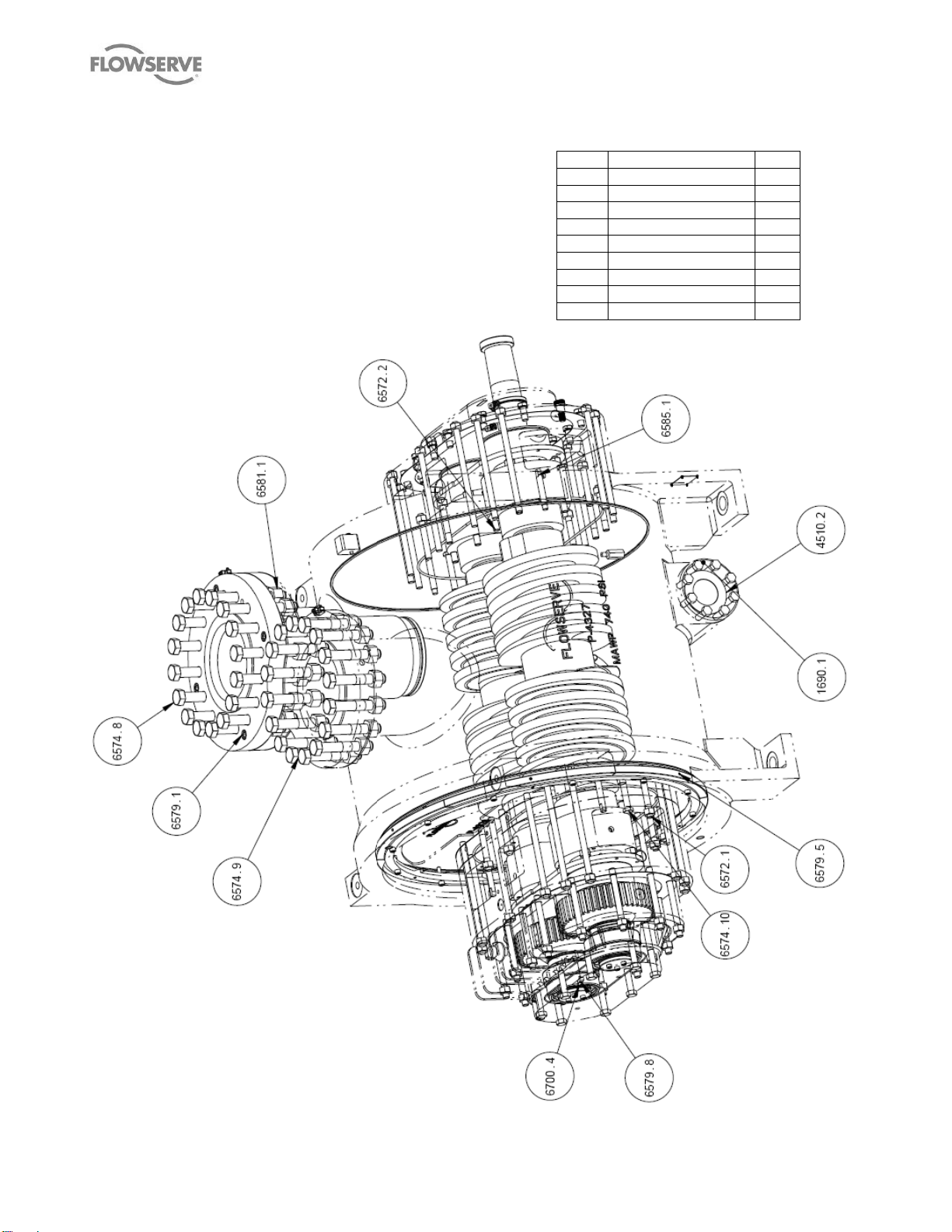
8.2 General Arrangement Drawing
REF
PART DESCRIPTION
QTY
1690.1
NON DRIVE END COVER
1
4510.2
GASKETS
2
6572.X
STUDS
X
6574.X
CAP SCREWS
X
6579.X
SHCS X 6875.8
TIMING GEAR DRIVEN
1
6581.X
HEX NUTS
X
6585.1
DOWEL PIN
4
6700.4
ANTI ROTATION KEY
1
The typical general arrangement drawing and any
specific drawings required by the contract will be sent
to the Purchaser separately unless the contract
specifically calls for these to be included into the User
Instructions. If required, copies of other drawings sent
separately to the Purchaser should be obtained from
the Purchaser and retained with these User
Instructions.
MP1 USER INSTRUCTIONS ENGLISH 26999958 – 10-12
Page 42 of 48 flowserve.com
Page 43

MP1 USER INSTRUCTIONS ENGLISH 26999958 – 10-12
REF NO
PART DESCRIPTION
QTY
1690.2
FLANGE BLIND
1
4610.X
O-RING
X
6574.X
CAP SCREWS
X
6578.1
PIPE PLUG
1
6578.3
ORIFICE
4
Page 43 of 48 flowserve.com
Page 44

MP1 USER INSTRUCTIONS ENGLISH 26999958 – 10-12
9 CERTIFICATION
Certificates, determined from the contract
requirements will be provided with this manual.
Examples are certificates for CE marking and ATEX
marking. If required, copies of other certificates sent
separately to the Purchaser should be obtained from
Purchaser for retention with the User Instructions.
10 OTHER RELEVANT DOCUMENTATION
AND MANUALS
10.1 Supplementary User Instruction
manuals
Supplementary instruction determined from the
contract requirements for inclusion into User
Instructions such as for a driver, instrumentation,
controller, sub-driver, seals, sealant system, mounting
component, etc., are included under this section. If
further copies of these are required they should be
obtained from the purchaser for retention with these
User Instructions.
Where any pre-printed set of User Instructions are
used, and satisfactory quality can be maintained only
by avoiding copying these, they are included at the
end of these User Instructions such as within a
standard clear polymer software protection envelope.
10.2 Change notes
If any changes, agreed with Flowserve Pump Division,
are made to the product after its supply, a record of
the details should be maintained with these User
Instructions.
10.3 Additional sources of information
Reference 1:
API Std 676, Positive Displacement Pumps – Rotary,
Third Edition, 2009
Reference 2:
Pumping Manual, 9th edition, T.C. Dickenson, Elsevier
Advanced Technology, United Kingdom, 1995.
Reference 3:
Pump Handbook, 2nd edition, Igor J. Karassik et al,
McGraw-Hill Inc., New York, 1993.
Reference 4:
ANSI/HI 1.1-1.5
Centrifugal Pumps - Nomenclature, Definitions,
Application and Operation.
Reference 5:
ANSI B31.3 - Process Piping.
11 OPTIONAL EQUIPMENT AND
ARRANGEMENTS
11.1 Jacketed components.
For pumps equipped with jacketed bodies and/or
stuffing boxes, the maximum allowable jacketed
pressure is 8.6 bar (125 PSIG] for steam or other
gaseous heat transfer media and 10.3 bar (150 PSIG]
for liquid heat transfer media (Dowtherm, Therminol]
unless otherwise specified on contract drawings. On
jacketed bodies, using steam, the inlet connection
should be at the highest connection on the body with
the outlet at the lowest connection on the opposite end
and side. This should be reversed when using a liquid
heat transfer medium. It is the user's responsibility to
ensure the normal steam temperature does not
exceed the defined maximum permitted value for the
particular Temperature Class.
There are two styles of jacket available, the integral
type and the bolt on type. The integral type need only
be connected as described whereas the bolt on type
must be installed per instructions using the heat
transfer cement supplied. Failure to do this will result
in uneven heat distribution within the pump and may
lead to premature failure.
Page 44 of 48 flowserve.com
Page 45

NOTES:
MP1 USER INSTRUCTIONS ENGLISH 26999958 – 10-12
Page 45 of 48 flowserve.com
Page 46

NOTES:
MP1 USER INSTRUCTIONS ENGLISH 26999958 – 10-12
Page 46 of 48 flowserve.com
Page 47

NOTES:
MP1 USER INSTRUCTIONS ENGLISH 26999958 – 10-12
Page 47 of 48 flowserve.com
Page 48

Your Flowserve factory contacts:
Flowserve Corporation
2300 E. Vernon Avenue
Vernon, CA 90058
USA
Telephone +1 (323) 587 6171
Fax +1 (323) 586 4138
Flowserve Pump Division
15 Worthington Dr.
PO Box 40
Brantford, Ontario, Canada
N3T 5M5
Telephone +1 (519) 753 7381
Fax +1 (519) 753 0845
Local Flowserve factory representatives:
To find your local Flowserve representative please
use the Sales Support Locator System found at
www.flowserve.com
FLOWSERVE REGIONAL SALES
OFFICES:
USA and Canada
Flowserve Corporation
5215 North O’Connor Blvd.
Suite 2300
Irving, TX 75039-5421 USA
Telephone 1 937 890 5839
Europe, Middle East, Africa
Flowserve Worthington S.r.l.
Via Rossini 90/92
20333 Desio (Milan), Italy
Telephone +39 0362-6121
Fax +39 0362 303 396
Latin America and Caribbean
Flowserve Corporation
6840 Wynnwood Lane
Houston, Texas 77008 USA
Telephone: +1 713 803 4434
Fax: +1 713 803 4497
Asia Pacific
Flowserve Pte. Ltd.
10 Tuas Loop
Singapore 637345
Telephone: +65 6771 0600
Telefax: +65 6862 2329
MP1 USER INSTRUCTIONS ENGLISH 26999958 – 10-12
 Loading...