

Page 1
®
Pump Division
Types: MNV and MNZ
(Vertical long shafted)
CENTRIFUGAL PUMPS
USER INSTRUCTIONS:
INSTALLATION, OPERATION, MAINTENANCE
PCN = 71569188 11- 04 (E) (incorporating MNV/MNZ.IOM)
These instructions should be read prior to installing
operating, using and maintaining this equipment.
Page 2

®
MNV & MNZ USER INSTRUCTIONS ENGLISH 71569188 11/04
CONTENTS
PAGE
CONTENTS............................................................... 2
1 INTRODUCTION AND SAFETY........................... 3
1.1 General ...........................................................3
1.2 CE marking and approvals..............................3
1.3 Disclaimer .......................................................3
1.4 Copyright......................................................... 3
1.5 Duty conditions ...............................................3
1.6 Safety..............................................................4
1.7 Nameplate and warning labels .......................8
1.8 Noise level ......................................................9
1.9 Specific machine performance......................10
2 TRANSPORT AND STORAGE........................... 10
2.1 Consignment receipt and unpacking ............10
2.2 Handling........................................................10
2.3 Lifting.............................................................10
2.4 Storage..........................................................11
2.5 Recycling and end of product life.................. 12
3 DESCRIPTION .................................................... 12
3.1 Nozzle configurations....................................13
3.2 Name nomenclature......................................14
3.3 Design of major parts.................................... 14
3.4 Performance and operating limits................. 15
4 INSTALLATION................................................... 16
4.1 Location ........................................................16
4.2 Part assemblies ............................................16
4.3 Foundation.................................................... 16
4.4 Grouting ........................................................17
4.5 Initial alignment............................................. 18
4.6 Piping ............................................................ 19
4.7 Electrical connections ................................... 21
4.8 Final shaft alignment check ..........................21
4.9 Protection systems........................................21
5 COMMISSIONING, START-UP, OPERATION AND
SHUTDOWN.................................................... 22
5.1 Pre-commissioning procedure...................... 22
5.2 Pump Lubrication.......................................... 22
5.3 Impeller clearance.........................................24
5.4 Direction of rotation.......................................24
5.5 Guarding .......................................................25
5.6 Priming and auxiliary supplies ......................25
5.7 Starting the pump..........................................25
5.8 Running or operation ....................................26
5.9 Stopping and shutdown.................................28
5.10 Hydraulic, mechanical and electrical duty... 28
6 MAINTENANCE .................................................. 28
6.1 Maintenance schedule.................................. 29
6.2 Spare parts....................................................35
6.3 Suggested spares and consumable items.... 36
6.4 Tools required ............................................... 36
6.5 Fastener torques...........................................36
6.6 Renewal clearances......................................36
PAGE
6.7 Disassembly ..................................................37
6.8 Examination of parts......................................39
6.9 Assembly.......................................................40
7 FAULTS; CAUSES AND REMEDIES..................41
8 PARTS LIST AND DRAWINGS...........................43
8.1 MNV cross section and parts list...................43
8.2 MNZ cross section and parts list ...................45
9 CERTIFICATION .................................................46
10 OTHER RELEVANT DOCUMENTATION AND
MANUALS........................................................46
10.1 Supplementary user instructions.................46
10.2 Change notes ..............................................46
INDEX
PAGE
Alignment of shafting (see 4.3, 4.5 and 4.7)
CE marking and approvals (1.2) ................................3
Clearances (see 6.6, Renewal clearances) .............36
Commissioning and operation (see 5) .....................22
Configurations (3.1)..................................................13
Direction of rotation (5.4)..........................................24
Dismantling (see 6.7, Disassembly).........................37
Duty conditions (1.5) ..................................................3
Electrical connections (4.7)......................................21
Examination of parts (6.8)........................................39
Faults; causes and remedies (7.0)...........................41
General assembly drawings (see 8) ........................43
Grouting (4.4)...........................................................17
Guarding (5.5)..........................................................24
Handling (2.2)...........................................................10
Hydraulic, mechanical and electrical duty (5.10) .....28
Lifting (2.3) ...............................................................10
Location (4.1) ...........................................................16
Lubrication schedule (see 5.2, Pump lubricants).....22
Maintenance schedule (6.1).....................................29
Piping (4.6)...............................................................19
Priming and auxiliary supplies (5.6).........................25
Reassembly (see 6.9, Assembly) ............................40
Replacement parts (see 6.3 and 6.4).......................36
Safety, protection systems (see 1.6 and 4.9)
Sound level (see 1.8, Noise level) .............................9
Specific machine performance (1.9) ........................10
Starting the pump (5.7) ............................................25
Stopping and shutdown (5.9)...................................26
Storage (2.4) ............................................................11
Supplementary user instructions (10.1) ...................46
Tools required (6.4)..................................................36
Torques for fasteners (6.5) ......................................36
Page 2 of 47
Page 3
®
MNV & MNZ USER INSTRUCTIONS ENGLISH 71569188 11/04
1 INTRODUCTION AND SAFETY
1.1 General
These instructions must always be kept
close to the product's operating location or
directly with the product.
Flowserve's products are designed, developed, and
manufactured with state-of-the-art technologies in
modern facilities. The unit is produced with great
care and commitment to continuous quality control,
utilizing sophisticated quality techniques, and safety
requirements.
Flowserve is committed to continuous quality
improvement and being at service for any further
information about the product in its installation and
operation or about its support products, repair and
diagnostic services.
These instructions are intended to facilitate
familiarization with the product and its permitted use.
Operating the product in compliance with these
instructions is important to help ensure reliability in
service and avoid risks. The instructions may not
take into account local regulations; ensure such
regulations are observed by all, including those
installing the product. Always coordinate repair
activity with operations personnel, and follow all plant
safety requirements and applicable safety and health
laws and regulations.
These instructions should be read prior to
installing, operating, using and maintaining the
equipment in any region worldwide. The
equipment must not be put into service until all
the conditions relating to safety noted in the
instructions, have been met.
1.2 CE marking and approvals
It is a legal requirement that machinery and
equipment put into service within certain regions of
the world shall conform with the applicable CE
Marking Directives covering Machinery and, where
applicable, Low Voltage Equipment, Electromagnetic
Compatibility (EMC), Pressure Equipment Directive
(PED) and Equipment for Potentially Explosive
Atmospheres (ATEX).
Where applicable the Directives and any additional
Approvals cover important safety aspects relating to
machinery and equipment and the satisfactory
provision of technical documents and safety
instructions. Where applicable this document
incorporates information relevant to these Directives
and Approvals. To confirm the Approvals applying
and if the product is CE marked, check the serial
number plate markings and the Certification. (See
section 9, Certification.)
1.3 Disclaimer
Information in these User Instructions is believed
to be reliable. In spite of all the efforts of
Flowserve Pump Division to provide sound and
all necessary information the content of this
manual may appear insufficient and is not
guaranteed by Flowserve as to its completeness
or accuracy.
Flowserve manufactures products to exacting
International Quality Management System Standards
as certified and audited by external Quality
Assurance organizations. Genuine parts and
accessories have been designed, tested, and
incorporated into the products to help ensure their
continued product quality and performance in use.
As Flowserve cannot test parts and accessories
sourced from other vendors the incorrect
incorporation of such parts and accessories may
adversely affect the performance and safety features
of the products. The failure to properly select, install,
or use authorized Flowserve parts and accessories is
considered to be misuse. Damage or failure caused
by misuse is not covered by Flowserve's warranty. In
addition, any modification of Flowserve products or
removal of original components may impair the safety
of these products in their use.
1.4 Copyright
All rights reserved. No part of these instructions may
be reproduced, stored in a retrieval system or
transmitted in any form or by any means without prior
permission of Flowserve Pump Division.
1.5 Duty conditions
This product has been selected to meet the
specifications of your purchaser order. The
acknowledgement of these conditions has been sent
separately to the Purchaser. A copy should be kept
with these instructions.
The product must not be operated beyond
the parameters specified for the application. If
there is any doubt as to the suitability of the
product for the application intended, contact
Flowserve for advice, quoting the serial number.
If the conditions of service on your purchase order
are going to be changed (for example liquid pumped,
temperature or duty) it is requested that the user
seeks Flowserve’s written agreement before start up.
Page 3 of 47
Page 4

®
MNV & MNZ USER INSTRUCTIONS ENGLISH 71569188 11/04
1.6 Safety
1.6.1 Summary of safety markings
These User Instructions contain specific safety
markings where non-observance of an instruction would
cause hazards. The specific safety markings are:
This symbol indicates electrical safety
instructions where non-compliance will involve a high
risk to personal safety or the loss of life.
This symbol indicates safety instructions where
non-compliance would affect personal safety and
could result in loss of life.
This symbol indicates “hazardous and toxic fluid”
safety instructions where non-compliance would affect
personal safety and could result in loss of life.
This symbol indicates safety
instructions where non-compliance will involve some
risk to safe operation and personal safety and would
damage the equipment or property.
This symbol indicates explosive atmosphere
zone marking according to ATEX. It is used in safety
instructions where non-compliance in the hazardous
area would cause the risk of an explosion.
This sign is not a safety symbol but
indicates an important instruction in the assembly
process.
1.6.2 Personnel qualification and training
All personnel involved in the operation, installation,
inspection and maintenance of the unit must be
qualified to carry out the work involved. If the
personnel in question do not already possess the
necessary knowledge and skill, appropriate training
and instruction must be provided.
If required the operator may commission the
manufacturer/supplier to provide applicable training.
Always coordinate repair activity with operations and
health and safety personnel, and follow all plant
safety requirements and applicable safety and health
laws and regulations.
1.6.3 Safety action
This is a summary of conditions and actions to
prevent injury to personnel and damage to the
environment and to equipment. For products
used in potentially explosive atmospheres
section 1.6.4 also applies.
NEVER DO MAINTENANCE WORK
WHEN THE UNIT IS CONNECTED TO POWER
GUARDS MUST NOT BE REMOVED WHILE
THE PUMP IS OPERATIONAL
DRAIN THE PUMP AND ISOLATE PIPEWORK
BEFORE DISMANTLING THE PUMP
The appropriate safety precautions should be taken
where the pumped liquids are hazardous.
FLUORO-ELASTOMERS (When fitted.)
When a pump has experienced temperatures over
250 ºC (482 ºF), partial decomposition of fluoroelastomers (example: Viton) will occur. In this
condition these are extremely dangerous and skin
contact must be avoided.
HANDLING COMPONENTS
Many precision parts have sharp corners and the
wearing of appropriate safety gloves and equipment
is required when handling these components. To lift
heavy pieces above 25 kg (55 lb) use a crane
appropriate for the mass and in accordance with
current local regulations.
THERMAL SHOCK
Rapid changes in the temperature of the liquid within
the pump can cause thermal shock, which can result
in damage or breakage of components and should be
avoided.
APPLYING HEAT TO REMOVE IMPELLER
There may be occasions when the impeller has either
been shrunk fit onto the pump shaft or has become
difficult to remove due to products that are corrosive in
nature.
If you elect to use heat to remove the impeller, it must
be applied with a great care and before applying heat
ensure any residual hazardous liquid trapped between
the impeller and pump shaft is thoroughly drained out
through the impeller keyway to prevent an explosion or
emission of toxic vapor.
Impeller design vary and so are the heat, applying
location and the duration of heat application. Contact
your nearest Flowserve service center for help.
Page 4 of 47
Page 5
®
MNV & MNZ USER INSTRUCTIONS ENGLISH 71569188 11/04
HOT (and cold) PARTS
If hot or freezing components or auxiliary heating
supplies can present a danger to operators and
persons entering the immediate area action must be
taken to avoid accidental contact. If complete
protection is not possible, the machine access must
be limited to maintenance staff only, with clear visual
warnings and indicators to those entering the
immediate area.
Bearing housings must not be insulated to
avoid drive motor and bearing heat up.
If the temperature is greater than 68 °C (175 °F) or
below 5 °C (20 °F) in a restricted zone, or exceeds
local regulations, action as above shall be taken.
HAZARDOUS LIQUIDS
When the pump is handling hazardous liquids care
must be taken to avoid exposure to the liquid by
appropriate siting of the pump, limiting personnel
access and by operator training. If the liquid is
flammable and/or explosive, strict safety procedures
must be applied.
Gland packing must not be used when pumping
hazardous liquids.
PREVENT EXCESSIVE EXTERNAL
PIPE LOAD
Do not use pump as a support for piping. Do not
mount expansion joints, unless allowed by Flowserve
in writing, so that their force, due to internal pressure,
acts on the pump flange.
ENSURE CORRECT LUBRICATION
(See section 5, Commissioning, start-up, operation
and shutdown.)
START THE PUMP WITH OUTLET
VALVE PARTLY OPENED
(Unless otherwise instructed at a specific point in the
User Instructions.)
This is recommended to minimize the risk of
overloading and damaging the pump motor at full or
zero flow. Pumps may be started with the valve
further open only on installations where this situation
cannot occur. The pump outlet control valve may
need to be adjusted to comply with the duty following
the run-up process. (See section 5, Commissioning
start-up, operation and shutdown.)
NEVER RUN THE PUMP DRY
INLET VALVES TO BE FULLY OPEN
WHEN PUMP IS RUNNING
Running the pump at zero flow or below the
recommended minimum flow continuously will cause
damage to the seal.
DO NOT RUN THE PUMP AT
ABNORMALLY HIGH OR LOW FLOW RATES
Operating at a flow rate higher than normal or at a
flow rate with no backpressure on the pump may
overload the motor and cause cavitation. Low flow
rates may cause a reduction in pump/bearing life,
overheating of the pump, instability and cavitation/
vibration.
1.6.4 Products used in potentially explosive
atmospheres
Measures are required to:
• Avoid excess temperature
• Prevent build up of explosive mixtures
• Prevent the generation of sparks
• Prevent leakages
• Maintain the pump to avoid hazard
The following instructions for pumps and pump units
when installed in potentially explosive atmospheres
must be followed to help ensure explosion protection.
Both electrical and non-electrical equipment must
meet the requirements of European Directive
94/9/EC.
1.6.4.1 Scope of compliance
Use equipment only in the zone for which it is
appropriate. Always check that the driver, drive
coupling assembly, seal and pump equipment are
suitably rated and/or certified for the classification of the
specific atmosphere in which they are to be installed.
Where Flowserve has supplied only the bare shaft
pump, the Ex rating applies only to the pump. The
party responsible for assembling the pump set shall
select the coupling, driver and any additional
equipment, with the necessary CE Certificate/
Declaration of Conformity establishing it is suitable for
the area in which it is to be installed.
The output from a variable frequency drive (VFD) can
cause additional heating affects in the motor and the
ATEX Certification for the motor must state that it is
covers the situation where electrical supply is from
the VFD. This particular requirement still applies
even if the VFD is in a safe area.
Page 5 of 47
Page 6
®
Temperature
class to
prEN 13464
Temperature limit of liquid
handled (* depending on
material and construction
variant
lower)
MNV & MNZ USER INSTRUCTIONS ENGLISH 71569188 11/04
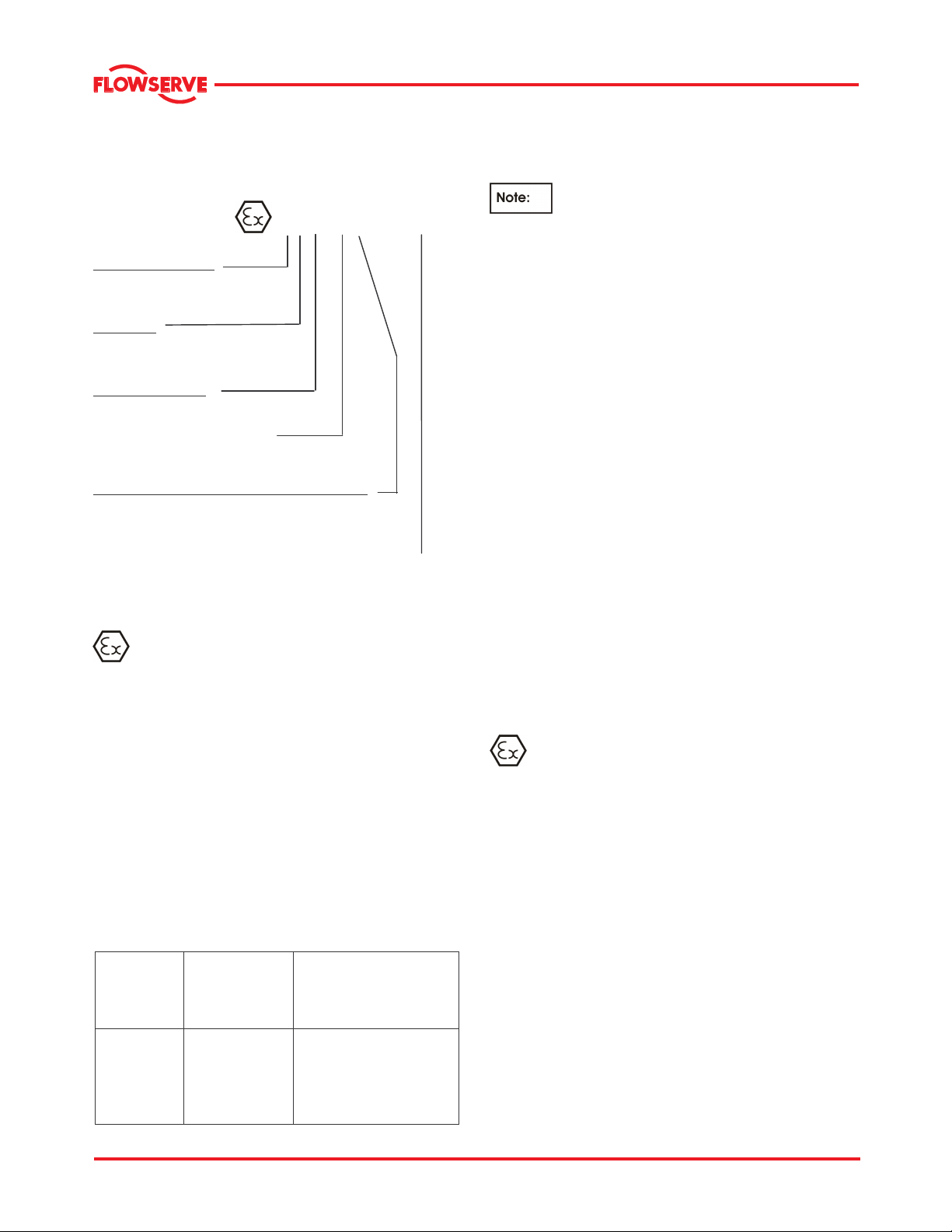
1.6.4.2 Marking
An example of ATEX equipment marking is shown
below. The actual classification of the pump will be
engraved on the nameplate.
II 2 GD c IIC 135 ºC (T4)
Equipment Group
I = Mining
II = Non-mining
Category
2 or M2 = High level protection
3 = normal level of protection
Gas and/or Dust
G = Gas; D= Dust
c = Constructional safety
(in accordance with prEn13463-5)
Gas group (Equipment Category 2 only)
IIA – Propane (typical)
IIB – Ethylene (typical)
IIC – Hydrogen (typical)
Maximum surface temperature (Temperature Class)
(See section 1.6.4.3.)
1.6.4.3 Avoiding excessive surface temperatures
ENSURE THE EQUIPMENT TEMPERATURE
CLASS IS SUITABLE FOR THE HAZARD ZONE
Pumps have a temperature class as stated in the
ATEX Ex rating on the nameplate. These are based
on a maximum ambient of 40 °C (104 °F); refer to
Flowserve for higher ambient temperatures.
The surface temperature on the pump is influenced
by the temperature of the liquid handled. The
maximum permissible liquid temperature depends on
the temperature class and must not exceed the
values in the table that follows.
The temperature rise at the seals and bearings and
due to the minimum permitted flow rate is taken into
account in the temperatures stated.
Maximum
T6
T5
T4
T3
T2
T1
surface
temperature
-5
permitted
85 °C (185 °F)
100 °C (212 °F)
135 °C (275 °F)
200 °C (392 °F)
300 °C (572 °F)
450 °C (842 °F)
- check which is
Consult Flowserve
Consult Flowserve
115 °C (239 °F) *
180 °C (356 °F) *
275 °C (527 °F) *
400 °C (752 °F) *
The responsibility for compliance with the
specified maximum liquid temperature is with the
plant operator.
Temperature classification “Tx” is used
when the liquid temperature varies and the pump
could be installed in different hazarous atmospheres.
In this case the user is responsible for ensuring that
the pump surface temperature does not exceed that
permitted in the particular hazardous atmosphere.
If an explosive atmosphere exists during the
installation, do not attempt to check the direction of
rotation by starting the pump unfilled. Even a short
run time may give a high temperature resulting from
contact between rotating and stationary components.
Wherever there is any risk of the pump being run
against a closed valve generating high liquid and
casing external surface temperatures, it is
recommended that users fit an external surface
temperature protection device.
Avoid mechanical, hydraulic or electrical overload by
using motor overload trips, temperature monitor or a
power monitor and make routine vibration monitoring
checks.
In dirty or dusty environments, regular checks must
be made and dirt removed from areas around close
clearances, bearing housings and motors.
1.6.4.4 Preventing the build up of explosive
mixtures
ENSURE THE PUMP IS PROPERLY FILLED
AND VENTED AND DOES NOT RUN DRY
Ensure the pump and relevant suction and discharge
pipeline system is totally filled with liquid at all times
during the pump operation, so that an explosive
atmosphere is prevented. In addition it is essential to
make sure that seal chambers, auxiliary shaft seal
systems and any heating and cooling systems are
properly filled.
If the operation of the system cannot avoid this
condition, fitting of an appropriate dry run protection
device is recommended.
To avoid potential hazards from fugitive emissions of
vapor or gas to atmosphere, the surrounding area
must be well ventilated.
Page 6 of 47
Page 7

®
MNV & MNZ USER INSTRUCTIONS ENGLISH 71569188 11/04
1.6.4.5 Preventing sparks
To prevent a potential hazard from mechanical
contact, the coupling guard must be non-sparking
and anti-static for Category 2.
To avoid the potential hazard from random induced
current generating a spark, the earth contact on the
baseplate must be used.
Avoid electrostatic charge: do not rub non-metallic
surfaces with a dry cloth; ensure cloth is damp.
The coupling must be selected to comply with 94/9/EC
and correct alignment must be maintained.
1.6.4.6 Preventing leakage
The pump must only be used to handle liquids
for which it has been approved to have the correct
corrosion resistance.
Avoid entrapment of liquid in the pump and
associated piping due to closing of suction and
discharge valves, which could cause dangerous
excessive pressures to occur if there is heat input to
the liquid. This can occur if the pump is stationary or
running.
Bursting of liquid containing parts due to freezing
must be avoided by draining or protecting the pump
and ancillary systems.
Where there is the potential hazard of a loss of a seal
barrier fluid or external flush, the fluid must be
monitored.
If leakage of liquid to atmosphere can result in a
hazard, the installation of a liquid detection device is
recommended.
1.6.4.7 Maintenance to avoid the hazard
It is recommended that a maintenance plan and
schedule is adopted to include the following. (See
section 6, Maintenance.)
a) Any auxillary systems installed must be
monitored, to ensure they function correctly.
b) Gland packings must be adjusted correctly to
give visible leakage and concentric alignment of
the gland follower to prevent excessive
temperature of the packing or the follower.
c) Check for any leaks from gaskets and seals. The
correct functioning of the shaft seal must be
checked regularly.
d) Chck bearing lubricant level,and verify if the
hours run show a lubricant change is required.
e) Check the duty condition is in the safe operating
range for the pump.
f) Check vibration, noise level and surface
temperarture at the bearings to confirm
satisfactory operation.
g) Check that dirt and dust are removed from areas
around close clearances, bearing housings and
motors.
h) Check coupling alignment and re-align if
necessary.
CORRECT MAINTENANCE IS REQUIRED TO
AVOID POTENTIAL HAZARDS WHICH GIVE A
RISK OF EXPLOSION
The responsibility for compliance with
maintenance instructions is with the plant
operator.
To avoid potential explosion hazards during
maintenance, the tools, cleaning and painting
materials used must not give rise to sparking or
adversely affect the ambient conditions. Where there
is a risk from such tools or materials, maintenance
must be conducted in a safe area.
Page 7 of 47
Page 8
®
MNV & MNZ USER INSTRUCTIONS ENGLISH 71569188 11/04
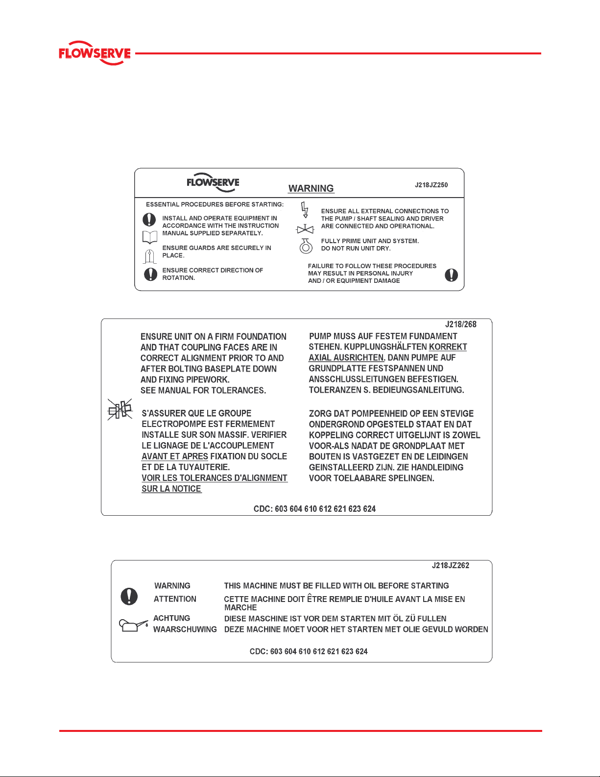
1.7 Nameplate and warning labels
1.7.1 Nameplate
For details of nameplate, see the Declaration of
Conformity /Flowserve documentation provided or
contact Flowserve for help.
1.7.2 Warning labels
Oil lubricated units only
Page 8 of 47
Page 9

®
MNV & MNZ USER INSTRUCTIONS ENGLISH 71569188 11/04
1.8 Noise level
Whenever pump noise level exceeds 85 dBA, attention must be given to prevailing Health and Safety
Legislation, to limit the exposure of plant operating personnel to the noise. Typical safety level requires to limit
the sound level of 90 dBA for 8 hours of exposure and the allowable dBA value increases 5 dBA for each
halving of exposure time. The usual approach is to control exposure time to the noise or to enclose the
machine to reduce emitted sound.
You may have already specified a limiting noise level when the equipment was ordered, however if no noise
requirements were defined then machines above a certain power level will exceed 85 dBA. In such situations,
consideration must be given to the fitting of an acoustic enclosure to meet local regulations.
1.8.1 Typical sound levels for MNV & MNZ pumps
Typical sound pressure levels measured in dB, and are A-weighted.
Motor
Frame
Size.
NEMA
Sound pressure values indicated for the motor are extracted from typical motor manufacturer’s data at no load
conditions and are not guaranteed. They may vary depending on the type of motor, enclosure used, and the
manufacturer. The sound pressure values for the pump are estimated levels in free field measured 1 meter from the
nearest major pump surface and at a height of 1.5 meters above the floor. using speed, flow rate, motor horsepower,
number of impeller vanes, and other variables. Therefore values indicated are for reference only and could exceed
the estimated values by as much as 8~10 dBA depending upon factors such as installed conditions, building
acoustics, foundation, piping, operating conditions, surrounding machinery. It is highly recommended to take actual
field measurement of sound pressure values, apply enclosures and safety measures mandated by the local
authorities and prevailing safety regulations. For all other pump and motor frame size combinations, the sound
levels have to measured and safety measures have to be adopted.
RPM Motor Only
Sound
Pressure
(dBA )
1800 60.0 65 70 180
1200 & slower 55.0 55 63
1800 60.0 65 69 210
1200 & slower 55.0 56 63
1800 70.0 77 77 250
1200 & slower 60.0 68 69
1800 70.0 77 77 280
1200 & slower 60.0 68 69
1800 65.0 77 77 320
1200 & slower 65.0 69 69
1800 65.0 77 78 360
1200 & slower 65.0 68 69
1800 70.0 77 78 400
1200 & slower 65.0 68 69
1800 70.0 77 78 440
1200 & slower 65 68 69
Pump only
Sound
Pressure
(dBA )
Combination
of pump and
motor
Sound
pressure
(dBA)
For units driven by equipment other than electric motors or units contained within enclosures, see the
accompanying information sheets and manuals.
Page 9 of 47
Page 10
®
MNV & MNZ USER INSTRUCTIONS ENGLISH 71569188 11/04
1.9 Specific machine performance
For performance parameters see section 1.5, Duty
conditions. When the contract requirement specifies
these to be incorporated into User Instructions these
are included here. In cases where performance data
has been supplied separately to the purchaser these
should be obtained and retained with these User
Instructions, if required.
2 TRANSPORT AND STORAGE
2.1 Consignment receipt and unpacking
Immediately after receipt of the equipment it must be
checked against the delivery and shipping
documents for its completeness and that there has
been no damage in transportation.
Any shortage and or damage must be reported
immediately to Flowserve Pump Division and must
be received in writing within one month of receipt of
the equipment. Claims made later than this specified
time period will not be accepted.
Check any crate, boxes, and wrappings for any
accessories or spare parts that may be packed
separately with the equipment or attached to
sidewalls of the box or equipment.
Each product has a unique serial number. Check
that this number corresponds with that advised and
always quote this number in correspondence as well
as when ordering spare parts or further accessories.
2.2 Handling
Boxes, crates, pallets or cartons may be unloaded
using forklift vehicles or slings dependent on their
size and construction.
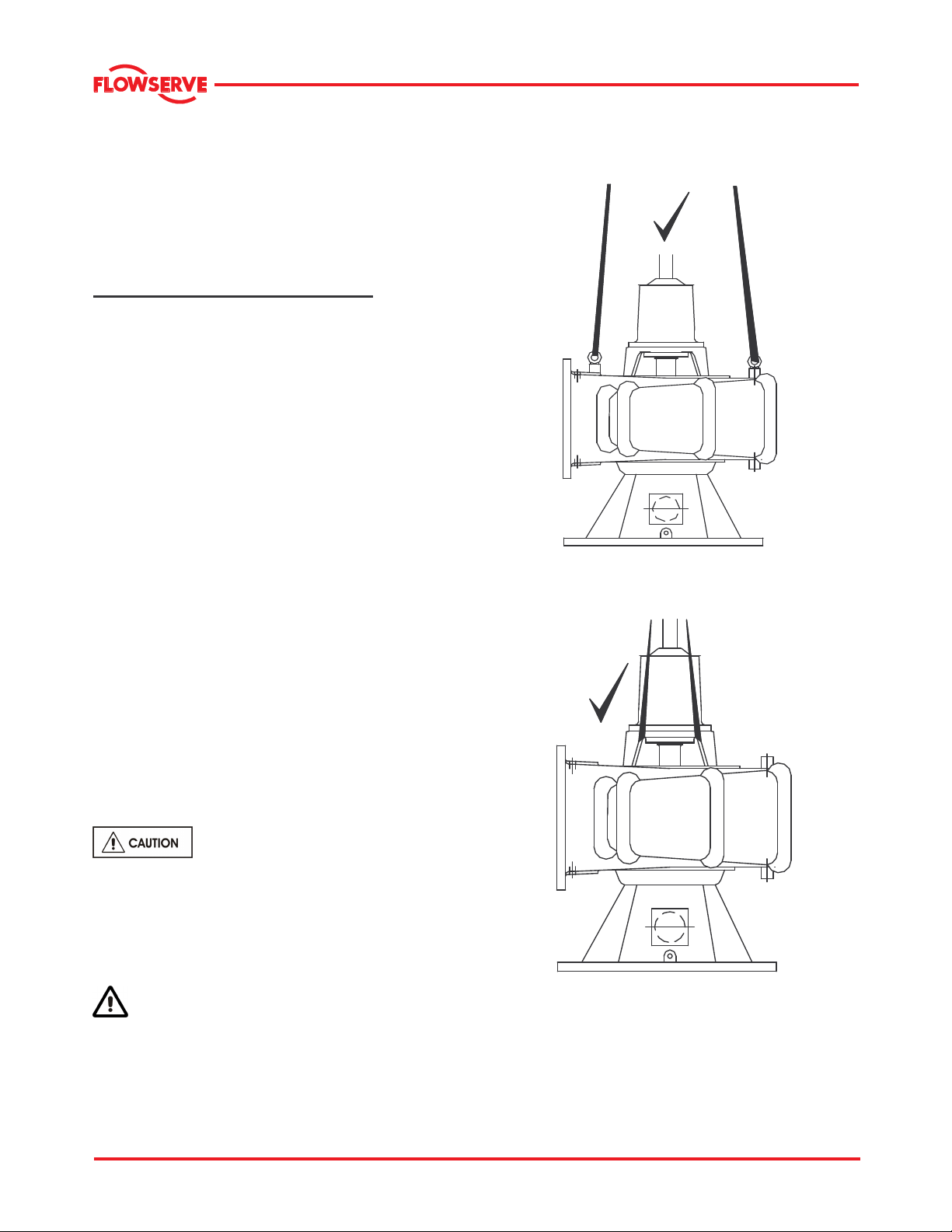
2.3 Lifting
2.3.1 Lifting of pump together with the suction
elbow/nozzle
(only MNZ configuration is shown in this illustration)
To avoid distortion, the pump unit
should be lifted as shown in sections 2.3.1.
It is strongly recommended to lift the pump using
appropriate equipments and proven procedures. It is
strongly recommended to employ experts for the task
to avoid injury or loss of life.
A crane must be used for all pump sets in
excess of 25 kg (55 lb). Fully trained personnel must
carry out lifting, in accordance with local regulations.
Page 10 of 47
Use stuffing box head and /or lifting eyes (if provided)
on the casing for lifting. Make sure to balance the
weight such that there is no tilting to any one side.
Page 11
®
MNV & MNZ USER INSTRUCTIONS ENGLISH 71569188 11/04
2.3.2 Lifting of driver
Use driver lifting lugs/ or follow driver manufacturer’s
User Instructions.
A crane must be used for all pump sets in
excess of 25 kg (55 lb). Fully trained personnel must
carry out lifting, in accordance with local regulations.
The driver and pump weights to be noted before
lifting is attempted.
2.4 Storage
Store the pump in a clean, dry location
away from vibration. Leave piping connection covers
in place to keep dirt and other foreign material out of
pump casing. Turn pump at intervals to prevent
brinelling of the bearings and the seal faces (if fitted),
from sticking.
2.4.1 Inspection before storage
a) Inspect the preservative coating/painted surfaces
on the various parts. Touch up whereever
necessary.
b) Inspect all covers over pump openings and piping
connections. If found damaged, remove the
covers and inspect interiors of the opening for any
deposits of foreign materials or water.
c) If necessary, clean and preserve the interior parts
as noted above to restore the parts to the "as
shipped" condition. Replace covers and fasten
securely.
2.4.2 Short term storage (less than 6 months)
When it is necessary to store a pump for a short time
before it can be installed, place it in a dry location
and protect it thoroughly from moisture.
When protective flanges are bolted to the suction and
discharge nozzles at the factory, they should not be
removed. Protect the bearings and the shaft against
moisture, dirt, or other foreign matter. To prevent
rusting in or seizing, lubricate the unit; see Section
5.2, Pump Lubricants. Rotate the pump shaft a
minimum of 5 revolutions every two weeks to keep
the bearings coated with lubricant and to minimize
the effects of brinelling.
MNV and MNZ standard pumps are
grease lubricated. Oil lubricated anti-friction bearings
are factory lubricated to prevent rusting for a short
period of time only. It is important to fill the
recommended oil lubricant to proper level
immediately upon receiving the equipment.
2.4.3 Long term storage (6 months and over)
More thorough precautions are required if
the pump is scheduled to be stored for an extended
period of time. Contact Flowserve before long-term
storage is attempted for specific storage
requirements and warranty information.
The following is a general procedure and could vary
depending upon the pump design and specific
application.
The storage area should be a clean
and dry. The storage location not be subjected to
rapid changes in temperature, light (no direct lighting)
or humidity, and relatively free of ground transmitted
vibration due to heavy construction and/or
machinery.
A temperature range of 5 o to 50 oC ( 40 o to 120o F)
with non-condensing humidity is recommended.
a) Drain fluid from the pump, rotate the pump rotor
once in the proper direction and blow the liquid
end dry with air.
b) Coat the interior surfaces of the liquid end with
rust inhibitor by brushing, spraying or fogging.
Rotate the pump shaft one turn in the proper
direction while coating.
c) Remove the packing and seal cage from the
stuffing box to prevent corrosion due to
condensation. Coat the interior machined
surfaces of stuffing box with a rust inhibitor. This
step may be omitted if the pumps are stored prior
to initial use.
d) For grease lubricated bearing frames, fill the
cavity between the bearing covers and bearings
with a good grade of NGLI No. 2 lithium base
grease to prevent contamination of the bearings.
Ensure the bearings are thoroughly packed with
grease. Lubrication quality and quantity must be
checked every six months and replaced or
replenished as necessary.
e) Coat all threaded openings with rust inhibitor and
plug. Coat machined surfaces of exposed
flanges with rust inhibitor and then cover with
fiberboard or wood flange covers. Desiccant
bags should be secured to the covers prior to
putting them in place and must not contact metal
surfaces.
f) Coat exposed, unpainted, and machined
surfaces with a rust inhibitor.
Page 11 of 47
Page 12
®
MNV & MNZ USER INSTRUCTIONS ENGLISH 71569188 11/04
g) Cover openings in the stuffing box head between
the casing and bearing frame with plastic, taped
in place, to prevent entrance of contaminants into
the stuffing box and line bearing area.
h) Cover the entire pump with a clear plastic sheet
for protection from dust, dirt moisture, etc. and to
allow for visual inspection. The cover should be
open near the top to allow for ventilation.
i) Rotate the pump shaft a minimum of 5
revolutions every two weeks to keep the bearings
coated with lubricant and to minimize the effects
of brinelling.
j) Refer to the vendors instruction manuals for
extended storage procedure for motors, controls,
coupling, etc.,
k)
Prior to start up or installation, an Flowserve
representative should be hired to inspect all
equipment to determine if any damage or
deterioration of parts has occurred and that the
equipment is in "as shipped" condition.
2.5 Recycling and end of product life
At the end of the service life of the product or its
parts, the relevant materials and parts should be
recycled or disposed of using an environmentally
acceptable method and local regulations. If the
product contains substances that are harmful to the
environment, these should be removed and disposed
of in accordance with current regulations. This also
includes the liquids and or gases that may be used in
the "seal system" or other utilities.
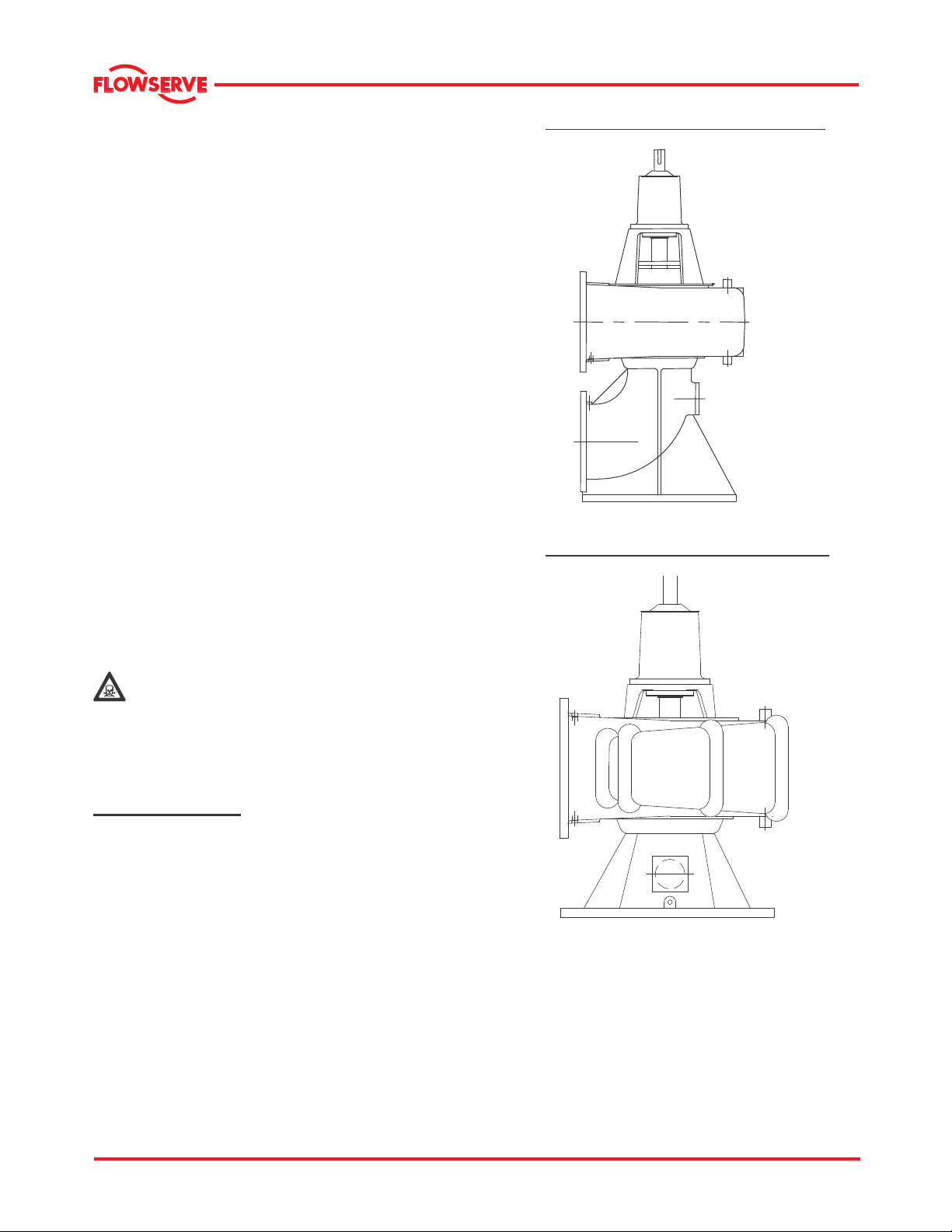
• Pump type MNV (with the suction elbow)
• Pump type MNZ (with the suction nozzle)
Make sure that hazardous substances are
disposed of safely and that the correct personal
protective equipment is used. The safety
specifications must be in accordance with the current
regulations at all times.
3 DESCRIPTION
The MNV/MNZ type pumps are single stage, volute
type, dry pit, centrifugal pumps designed for handling
sewage, storm water, dry dock and industrial waste
applications with end suction side discharge mix flow
non-clog design.
It should be noted that unscreened raw sewage may
introduce some chances of clogging and therefore
clogging may be totally avoided, if appropriate level
of screening is applied.
These are end suction side discharge mix flow nonclog pump. The information contained in this book
covers long shafted pumps where the pump and
driver are installed separately connected by one or
multiple shafting using universal joints (some
exceptional cases may have rigid or geared
couplings). Type MNV is fitted with a suction elbow
and MNZ with a suction nozzle.
Page 12 of 47
Page 13
®
MNV & MNZ USER INSTRUCTIONS ENGLISH 71569188 11/04
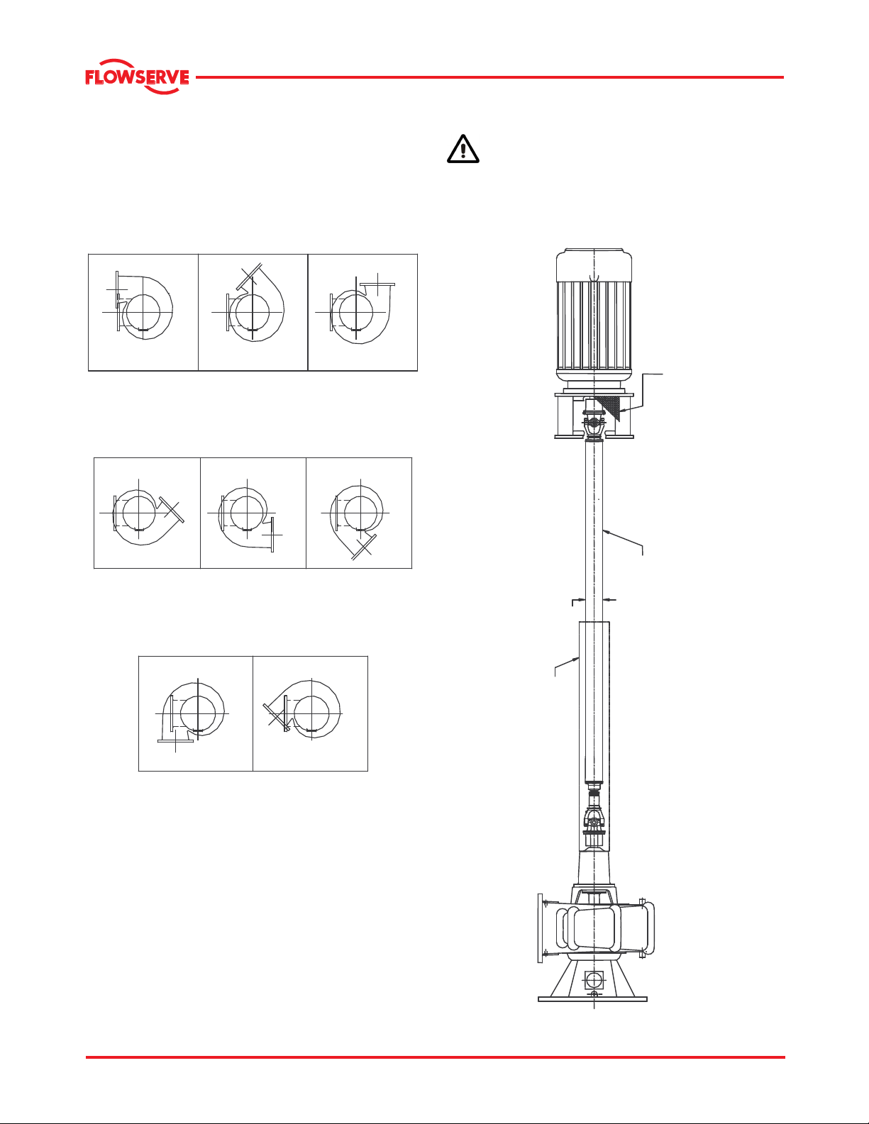
3.1 Nozzle configurations
The MNV and MNZ pumps are configured with
various nozzle positions, designated A-H as shown
(Example: for counter clock-wise rotation).
A
D
B
E
C
F
3.1.1 Long shafting with U-joints.
(Example shown is MNZ pump assembly).
Shaft guards are supplied if ordered. It is the
responsibility of the operators of drive shaft and
universal joints to provide and install guards or safety
devices, which may be required by recognized safety
standards.
GUARD
G
H
SHAFT
GUARD
U SHAFTING
TUBING
Page 13 of 47
Page 14
®
MNV & MNZ USER INSTRUCTIONS ENGLISH 71569188 11/04
3.2 Name nomenclature
The pump size will be engraved on the nameplate
typically as below:
24-MNV/MNZ-47
Nominal discharge branch size.
Type/Configuration – see sec. 3.0.
Nominal impeller diameter.
(Size in inches only)
The typical nomenclature above is the general guide
to the MNV/MNZ configuration description. Identify
the actual pump size and serial number from the
pump nameplate. Check that this agrees with the
applicable certification provided.
3.3 Design of major parts
3.3.1 Pump casing & stuffing box head
The pump casing with its integrally cast discharge
nozzle is of the volute type. It is machined to provide
a rabbet fit for the stuffing box head and suction
head. The heads are removable and are bolted to
and centered in the casing. The casing and suction
head are each provided with one hand hole for
inspection and cleaning of the pump without
dismantling. The pump has its main casing gasket
axial to the shaft allowing maintenance to the rotating
element by separating the impeller assembly from
the casing. Suction and discharge branches remain
undisturbed
3.3.2 Impeller and wearing rings
The impeller is a solids handling type capable of
passing trash and solids of limited size. The impeller
hub is keyed to the shaft and held in position by an
impeller nut which is set screwed to the impeller to
prevent its backing off. A pair of replaceable wearing
rings (optional) between the rotating impeller and the
stationary suction head are provided for impeller
wear resistance.
3.3.2.1 Impeller and wearing ring arrangement
IMPELLER
IMPELLER
WEARING RING
SUCTION HEAD
WEARING RING
SUCTION HEAD
3.3.3 Shaft and shaft sleeve
The pump shaft is sized to transmit the rated loads
encountered with liberal safety factors, and is
accurately machined over its full length. Generous
fillets are used to minimize stress concentrations. It
is protected from wear at the stuffing box by a
removable shaft sleeve.
3.3.4 Pump bearings and lubrication
MNV & MNZ pumps are equipped with anti-friction
bearings of the tapered roller type. The line and
thrust bearings are arranged in opposed mounting
and can be furnished with grease as standard and
custom built oil lubricated pumps.
3.3.5 Bearing housing
Bearings are mounted in a removable cast iron
bearing frame. The frame casting offers solid support
and location to the bearings and two grease nipples
enable grease lubricated bearings to be replenished
between major service intervals.
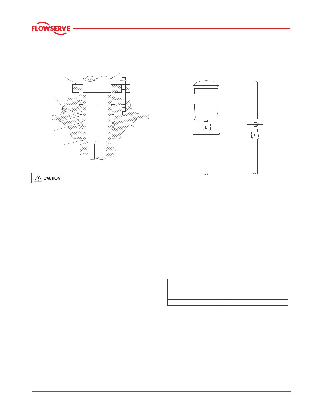
3.3.6 Stuffing box housing
The stuffing box housing cast integrally with the back
head and has designed number of sealing options.
For applications requiring Mechanical Seals refer to
the Mechanical Seal Manufacturer's instructions.
Packing within the pump stuffing box seals the pump
against leakage along the shaft at the point where it
passes through the stuffing box. It should be packed
with rings of braided, non-asbestos packing and a
seal cage. It is equipped with a split removable
packing gland.
Page 14 of 47
Page 15
®
MNV & MNZ USER INSTRUCTIONS ENGLISH 71569188 11/04
The number of packing rings list is provided in
section 6.1.8.1. Place two rings of packing below the
seal cage and the remaining rings above the seal
cage.
PACKING GLAND
SEAL WATER
CONNECTION
SEAL CAGE
PACKING
SHAFT SLEEVE
PUMP SHAFT
STUFFING BOX
HEAD
IMPELLER
The stuffing box is not packed when
the pump is shipped.
A water supply of approximately 0.113 to 0.227 m3/h
(0.5 to 1.0 gpm) is to be introduced to the seal water
connection to provide for packing lubrication and
sealing. A steady "trickle" of water from the stuffing
box will indicate proper adjustment. The sealing
water supply pressure should be 0.35 to 0.69 bar (5
to 10 psi) above the pump discharge pressure.
When grease sealing is used, a similar grease
pressure should be maintained. A slight leakage of
liquid from the stuffing box is to be expected and the
gland MUST NOT be tightened to the point of
stopping the leakage.
3.3.7 Shaft seal
The mechanical seal(s) attached to the pump shaft
seals the pumped liquid from the environment.
Gland packing may be fitted as an option. See
section 6.1.9 for mechanical seal maintenance
information.
3.3.8 Driver
The driver is normally an electric motor. Different
drive configurations may be fitted such as internal
combustion engines, turbines, hydraulic motors etc.,
driving via couplings, belts, gearboxes, drive shafts.
All metal flexible couplings are normally used for
connecting pump and drive shafts. For operating
instructions, refer to the coupling manufacturer's User
Instructions.
3.3.9 Intermediate shafting
Steel flexible shafting with universal joint couplings is
usually used with MNV/MNZ pump installations. For
operating instructions, refer to the U shaft
manufacturer's User Instructions. See below for
illustrations of driver and intermediate U-joint shafting.
3.3.10 Accessories
Accessories may be fitted when specified by the
customer
3.4 Performance and operating limits
This product has been selected to meet the
specifications of your purchase order. See section 1.5.
The following data is included as additional information to
help with your installation. It is typical, and factors such
as temperature, materials, and seal type may influence
this data. If required, a definitive statement for your
particular application can be obtained from Flowserve.
3.4.1 Operating limits
Pumped liquid temperature
limits*
Maximum ambient
temperature*
Maximum pump speed refer to the nameplate
*Subject to written agreement from Flowserve. Special designs
and materials may be available for pumps operating above and
below these specified limits. Contact Flowserve for upgrade
options available for your specific application.
3.4.2 Pump and impeller data
Details of impeller diameter (trim), wearing ring
diameter, are normally provided with the pump along
with the test curve data. If not found with the pump,
please contact Flowserve representative.
5 ºC (40 ºF) to +80 ºC (176 ºF)
5 ºC (40 ºF) to +40 ºC (104 ºF)
Page 15 of 47
Page 16

®
MNV & MNZ USER INSTRUCTIONS ENGLISH 71569188 11/04
4 INSTALLATION
Equipment operated in hazardous locations
must comply with the relevant explosion protection
regulations. See section 1.6.4, Products used in
potentially explosive atmospheres.
Inspection prior to installation: Six months prior to
the scheduled installation date, a Flowserve Pump
Division representative is to be employed to conduct
an inspection of the equipment and the facility. If any
deterioration of equipment is noticed, the Flowserve
Pump Division representative may require a partial or
complete dismantling of the equipment including
restoration and replacement of some components.
4.1 Location
The pump should be located to allow room for
access, ventilation, maintenance and inspection with
ample headroom for lifting and should be as close as
practicable to the supply of liquid to be pumped.
4.1.1 General installation check-list
The following checks should be made before starting
actual installation.
a) Make sure that the motor nameplate ratings and
the power supply system match correctly.
b) Check the sump depth and suction pipe length
match up.
c) Check the liquid level in the sump.
d) Check the installation equipment to be sure that it
will safely handle the pump weight and size.
e) Check all pump connections (bolts, nuts etc) for
any shipping and handling related problems.
f) Check for any evidence of lubricant leakage at
the bearings.
g) Check that the shaft rotates freely.
4.1.2 Cleaning prior to installation
Remove the rust inhibitor, flange protectors, plastic
covers, desiccant, and inspect the inside of the
pump. Repack the stuffing box and ensure that the
stuffing box drain is clear. Flush the bearings using a
hot, light oil at 82o to 93oC (180o to 200o F) while the
shaft is slowly rotated. Re-lubricate the bearings as
explained in Section 5.0
4.1.3 Manufacturer’s service
It is recommended that the services of Flowserve
Company Service Representative be employed for
installing and starting the pump as proper installation
is vital for designed functioning, performance and
reliability of the equipment.
4.1.4 Site preparation
Care should be taken to prevent an out of service
pump from freezing during cold weather. Draining
the pump is recommended when there is any
possibility of freezing.
Observe extreme caution when
priming, venting and draining hazardous liquids.
Wear protective clothing in the presence of
hazardous, caustic, volatile, flammable and hot
liquids. Do not breathe toxic vapors. Do not
swallow. Do not allow sparking, flames or hot
surfaces in the vicinity of the equipment.
4.1.5 General tools required for installation
a) Mobile crane capable of hoisting and lowering the
pump and/or motor.
b) Sets of chains, tongs and cable slings for
attaching it to the pump and motor lifting eyes.
c) General purpose hand tools, pipe wrenches, end
wrenches, socket set, screwdrivers, Allen
wrenches, wire brush, scraper and fine emery
cloth.
d) Thread sealing compound designed for stainless
steel and light machinery oil.
4.2 Part assemblies
Motors are supplied separately for MNV/MNZ pumps.
It is the responsibility of the installer to ensure that
the motor is assembled to the pump and lined up as
detailed in section 4.5. It is also the responsibility of
the installer to take note of the pump and driver
weights for proper handling before assembly is
attempted.
4.3 Foundation
There are many methods of installing
pump units to their foundations. The correct method
depends on the size of the pump unit, its location and
limitations on its noise/vibrations. Non-compliance
with the provision of correct foundation and
installation may lead to failure of the pump and as
such, would be outside the terms of the warranty.
The foundation may consist of material that will afford
permanent, rigid support to the discharge head and
will absorb expected stresses that may be
encountered in service.
Concrete foundations should have anchor bolts
installed in sleeves that are twice the diameter of the
bolt to allow alignment and has holes in the mounting
plate as illustrated in the detail below.
Page 16 of 47
Page 17

®
MNV & MNZ USER INSTRUCTIONS ENGLISH 71569188 11/04
The foundation should be of sufficient strength to
absorb vibration (i.e., at least five times the weight of
the pump unit) and to form a permanent, rigid support
for the suction nozzle/steel frame support. This is
important in maintaining the alignment of a close
coupled unit. A concrete foundation on a solid base
should be satisfactory.
4.3.1 Pump and structural natural frequency
Pump manufacturers can calculate or determine the
natural frequency of the pump assembly, including
the driver. However, in a field installation, the
vibrating structure comprises, in addition to the pump
assembly, the foundation, the mounting, the piping,
and supports. The natural frequency of the vibrating
structure is determined by the stiffness of the total
structure and by its equivalent mass. The natural
frequency of the structure may therefore differ
significantly from the natural frequency of the pump.
In the absence of any specific information, the pump
manufacturer will assume that the piping is installed
rigidly and anchored close to the pump connections.
It will also be assumed that the hold down bolts are
securely embedded in a concrete foundation of
infinite mass and rigidity.
The system designer must give proper consideration
and must ensure that the natural frequency of the
vibrating structure, as defined above, does not fall
within the pump operating speed range. That person
also must be aware of the much lower stiffness of
fabricated system structures, relative to concrete,
and the problems associated with calculating
stiffness of unconventional and composite structures.
4.4 Grouting
The pump and motor must be aligned
on the base prior to grouting the base in place (see
alignment). To do otherwise will negate the factory
pre-alignment and may result in alignment difficulties
at the expense of others. Where applicable, grout in
the foundation bolts.
Grouting provides solid contact between the pump
unit and foundation, prevents lateral movement of
running equipment and dampens resonant vibrations.
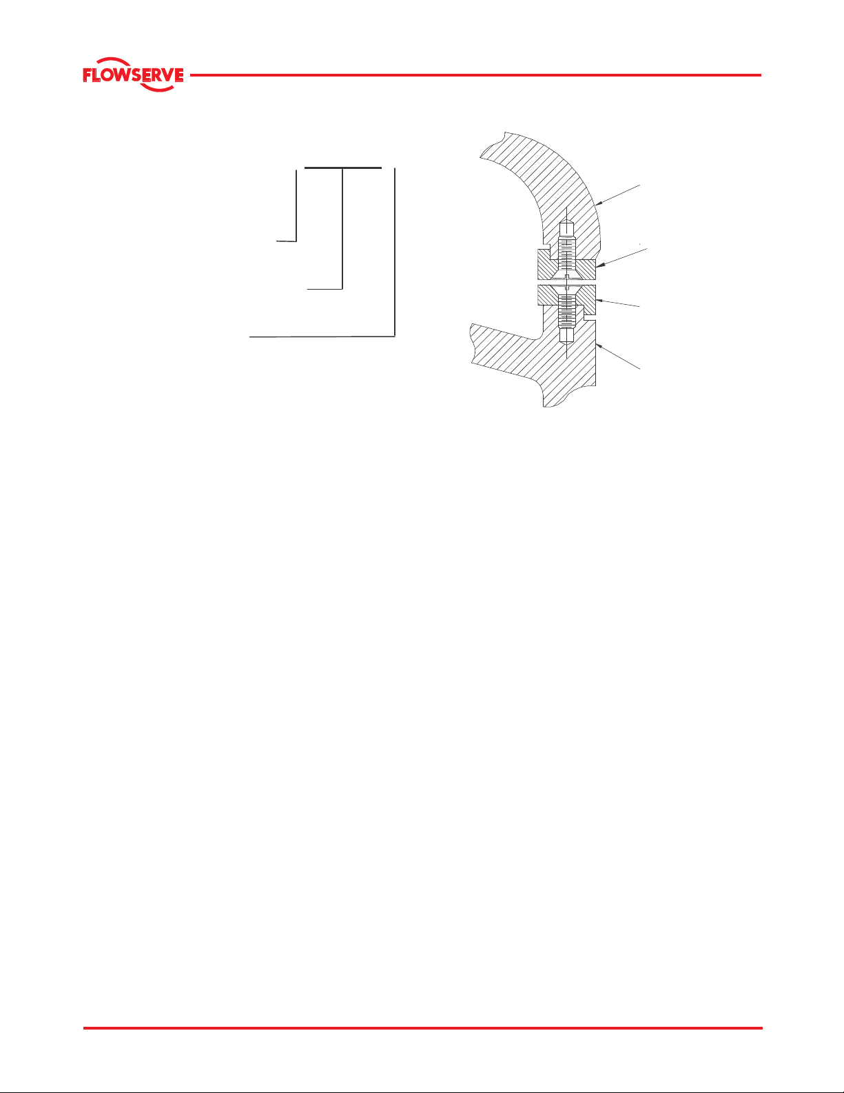
4.4.1 Typical foundation bolt arrangement
Foundation bolts of the specified size should be
embedded in concrete and located according to the
Elevation drawing. Each bolt should be surrounded
by a pipe sleeve at least two times the diameter of
the bolt. The sleeve should be held rigidly yet
allowing the bolts to be moved to conform to the
holes in the baseplate as shown in the detail under
this section.
PUMP FOOT
(IF SOLE PLATE IS USED)
SHIMS
FOUNDATION
GROUT
SLEEVE
PUMP FOOT
OR SOLE PLATE
FOUNDATION
BOLT
Foundation bolts should only be fully tightened when
the grout has cured.
Only non-shrinking grout with a 41.4 Mpa (6000 psi)
compressive strength in 72 hours should be used.
Flowserve recommends the following procedure for
grouting.
4.4.2 Recommended procedure for grouting
a) Build a wooden form around the outside of the
base to contain the grout. In some cases the form
is placed tightly against the lower edge of the base
and in other cases it is placed a slight distance
from the edge of the pump base.
b) Saturate the top of the rough concrete foundation
with water, if required before grouting. Add grout
until the entire area under the pump base is filled,
including the space between the foundation bolt
and pipe sleeve. A stiff wire should be used to
work the grout and release any air pockets.
c) After the grout is poured, the exposed surfaces
should be covered with wet burlap to effect slow
curing and prevent cracking. When the grout is
set (about 48 hours) remove the forms and
smooth the exposed surfaces if desired. The
grout should be allowed to cure at least 72 hours
before dynamically loaded.
If leveling nuts are used on the
foundation bolts to level the base, they must be
backed off as far as possible prior to grouting the
base in place. Shim near the foundation bolts, back
off the leveling nuts, and tighten the foundation bolts.
To do otherwise will significantly lower the structural
natural frequency and result in separation of the base
from the grout.
Page 17 of 47
Page 18

®
MNV & MNZ USER INSTRUCTIONS ENGLISH 71569188 11/04
4.5 Initial alignment
Ensure pump and driver are isolated
electrically and the half couplings are disconnected.
MNV/MNZ pumps are shipped from
the factory without the line shaft, pump or motor
couplings mounted. The couplings are mounted in
the field. Refer to the shafting manufacturer’s
instruction manual to determine the type of coupling
supplied with your unit.
Mount interference fit couplings by heating them
evenly in an oven to approximately 135 oC (275 oF).
This is required as the coupling flanges are designed
for an interference fit per AGMA Standard 9002. Do
not alter this fit. Upon removal from the oven,
position the hubs on the shafts, as required.
DO NOT hammer on the flanges in an
attempt to remove them from the shaft. To do so will
permanently damage the bearings in the pump
and/or the motor. Interference fit couplings have to
be removed by applying heat and a puller. The
alignment must be checked after the pump is
completely piped up.
4.5.1 Thermal expansion
The pump and motor will normally
have to be aligned at ambient temperature and
should be corrected to allow for thermal expansion at
operating temperature. In pump installations
involving high liquid temperatures, the unit should be
run at the actual operating temperature, shut down
and the alignment checked immediately.
4.5.2 Alignment methods
Ensure pump and driver are isolated
electrically and the couplings are disconnected.
The alignment MUST be checked.
Although the pump will have been aligned at the
factory, it is most likely that this alignment will have
been disturbed during transportation or handling. If
necessary, align the motor to the pump, not the pump
to the motor. Alignment is achieved by adding or
removing shims under the motor feet and also
moving the motor horizontally as required. In some
cases where the alignment cannot be achieved it will
be necessary to move the pump before
recommencing the above procedure.
4.5.3 Alignment Procedure
a) Set the pump with its support on the foundation.
Use shims to level and raise the pump in a vertical
direction. Ensure that the suction and discharge
flanges are level, plumb, and at the proper
elevation.
b) Place the motor on the motor base. Move and
shim beneath the motor base as necessary to
ensure that:
• The distance from the motor coupling to the
pump coupling is correct
• The motor to pump coupling offset is that
required to produce the correct misalignment
• The motor coupling and pump coupling are
level to one another
c) Tighten the motor base foundation bolts and
recheck the span, offset, and coupling level.
Grout the base in place.
d) Set the motor to pump coupling offset by sliding
the motor on the base.
e) Secure the motor to the motor base.
f) Install the intermediate shafting with the guide
bearing(s) in place. If more than one section of
the shaft is used. Check the shafting alignment.
The universal joints must be placed so that
the yoke ears on each section of shaft are in line with
one another. If the yoke ears are not aligned,
equipment vibration will be increased.
All the shafting misalignment must occur in
one plane; i.e., if the shafting were placed on a sheet
of paper, all of the sections must contact the paper
along their length with no sections protruding out of the
paper.
g) Align the guide bearings to the shaft by shimming
beneath the guide bearing as necessary. Secure
the guide bearings to the foundation. Recheck the
guide bearing and shafting alignment.
h) Tighten the pump foundation bolts and grout the
pump in place. Dowel the motor to the motor base
(two dowels diagonally opposed), and recheck
alignment.
Due to the many variations and complexity
of installations, it is recommended that a Flowserve
Pump Division Service Representative be hired to
assist in installation and alignment on long shafted
vertical units.
Page 18 of 47
Page 19

®
MNV & MNZ USER INSTRUCTIONS ENGLISH 71569188 11/04
4.5.4 Alignment criteria
Accurate alignment of pump and drive shafts is
essential for successful operation. Misalignment
values as near to zero tolerance as possible are
required for trouble free operation and long
equipment life.
Universal joints are used to compensate for slight
changes in alignment that occur during normal
operation. It is not used to correct for initial
misalignment in excess of the values herein.
Although most couplings can withstand greater
misalignment, such can cause excessive vibration
and premature equipment failure. Driver and driven
coupling faces must be parallel to each other within
one degree.
An offset not exceeding 3.2 mm (0.125 in.) to 4.8 mm
(0.187 in.) per foot is recommended. Although
universal joint type shafting will withstand much
greater misalignment, such can cause excessive
vibration as well as premature failure of the
equipment. Note that a small misalignment is required
to lubricate the universal joint bearings that use needle
bearings.
Steady Bearing centerlines are to be concentric with
the center line of the shaft to within one degree.
Pumps with thick flanged non-spacer couplings can
be aligned by using a straight-edge across the
outside diameters of the coupling hubs and
measuring the gap between the machined faces
using feeler gauges, measuring wedge or calipers.
When the electric motor has sleeve bearings it is
necessary to ensure that the motor is aligned to run
on its magnetic centerline.
Refer to the motor manual for details.
A button (screwed into one of the shaft ends) is
normally fitted between the motor and pump shaft
ends to fix the axial position.
If the motor does not run in its
magnetic centre the resultant additional axial force
may overload the pump thrust bearing.
Complete piping as below and see section 4.8,
Final shaft alignment, section 5, Commissioning,
start-up, operation, and shutdown before connecting
driver and checking actual rotation.
4.6 Piping
Protective covers are fitted to the pipe
connections to prevent foreign bodies entering during
transportation and installation. Ensure that these
covers are removed from the pump before
connecting any pipes.
4.6.1 Pipework velocities
In order to minimize friction losses and hydraulic
noise in the pipe work, it is a good practice to choose
pipe work that is one or two sizes larger than the
pump suction and discharge. Typically main pipe
work velocities should not exceed 2 m/s (6 ft/sec)
suction and 3 m/s (9 ft/sec) on the discharge.
Take into account the available NPSH that must be
higher than the required NPSH of the pump.
Never use the pump as a support for
piping.
4.6.1.1 Piping strains
Pipe strains are a common cause of misalignment,
hot bearings, worn couplings, and vibration.
Satisfactory operation cannot be maintained when
the piping imposes a force on the pump. Misaligned
piping flanges can spring and pull a pump out of
position when their bolts are drawn up.
Flanges must have flat faces and be brought
squarely together before the bolts are tightened.
To avoid breaking the flanges when tightening the
bolting, mating pipe flanges should also have flat
faces and full face gaskets should be used.
Suction and discharge pipes, and associated
equipment, should be supported and anchored near,
but independent of the pump so that no strain will be
transmitted to the pump casing.
Pipe couplings that are not axially rigid are
sometimes used in the discharge and/or suction
piping to avoid transmitting any piping strains caused
by system pressure, thermal expansion or pipe
misalignment. Such pipe couplings allow transmittal
to the pump, a force equal to the area of the
expansion joint times the pressure in the piping.
These forces can have a significant magnitude and it
is impractical to design the pump casing, base plate,
support, etc., to withstand them.
Page 19 of 47
Page 20
®
MNV & MNZ USER INSTRUCTIONS ENGLISH 71569188 11/04
Consequently, when pipe couplings lack axial rigidity,
a suitable pipe anchor must be installed between it
and the pump proper. Alternately, adequate
restraining devices should be used and properly
adjusted to prevent these forces from being
transmitted to the pump. Maximum forces and
moments allowed on the pump flanges vary with the
pump size and type.
To minimize these forces and moments that may, if
excessive, cause misalignment, hot bearings, worn
couplings, vibration and the possible failure of the
pump casing, the following points should be strictly
followed:
• Prevent excessive external pipe load
• Never draw piping into place by applying force to
pump flange connections
• Do not mount expansion joints so that their force,
due to internal pressure, acts on the pump flange
Ensure piping and fittings are flushed
before use.
Ensure piping for hazardous liquids is arranged
to allow pump flushing before removal of the pump.
4.6.2 Suction piping
Experience has shown that the major source of
trouble in centrifugal pump installations, other than
misalignment, is traceable to a faulty suction line.
The utmost attention must be given to this portion of
the installation to ensure that the pump receives
hydraulically stable flow. The suction piping should
be direct as possible and its length held to a
minimum. If a long suction line is required, increase
the pipe size to reduce friction losses. Then
gradually reduce the pipe size in steps before
entering the pump. The piping should be run without
having high spots and should have a continual rise
toward the pump. This prevents air pockets.
Clean out all debris from the suction line and wet well
prior to operating the pumps. Care should be
exercised to keep the suction piping air tight and
sealed against leakage.
Isolation valve in suction line is strongly
recommended to facilitate future servicing needs. An
isolation valve is recommended in the suction line, if
a positive head exists.
4.6.2.1 Suction piping guidelines
a) The inlet pipe should be one or two sizes larger
than the pump inlet bore and pipe bends should
be as large a radius as possible.
b) Pipe work reducers should have a maximum total
angle of divergence of 15 degrees.
c) On suction lift the piping should be inclined up
towards the pump inlet with eccentric reducers
incorporated to prevent air locks.
d) On positive suction, the inlet piping must have a
constant fall towards the pump.
e) Flow should enter the pump suction with uniform
flow, to minimize noise and wear. This is
particularly important on large or high-speed
pumps that should have a minimum of four
diameters of straight pipe on the pump suction
between the elbow and inlet flange.
f) Inlet strainers, when used, should have a net free
area of at least three times the inlet pipe area.
g) Do not install elbows at an angle other than
perpendicular to the shaft axis. Elbows parallel
to the shaft axis will cause uneven flow.
h) Except in unusual circumstances strainers are
not recommended in inlet piping. If considerable
foreign matter is expected a screen installed at
the entrance to the wet well is preferable.
i) Fitting an isolation valve will allow easier
maintenance.
j) Never throttle pump on suction side and never
place a valve directly on the pump inlet nozzle.
4.6.3 Discharge piping
A check valve and a gate valve are normally installed
in the discharge line. The check valve is normally
placed between the pump and the gate valve to
protect the pump from any excessive back pressure
and reverse rotation that may be caused by water
running back through the pump casing during a driver
or power failure. Any reverse flow through the pump
or excessive back pressure should be kept to an
absolute minimum. The check valve will also prevent
suspended solids from accumulating in the casing
and will increase wearing life.
• Pipe work reducers should have a maximum total
angle of divergence of 9 degrees.
• Fitting an isolation valve will allow easier
maintenance.
• A compound pressure gauge should be
connected to the suction and a pressure gauge
connected to the discharge side of each pump.
Mount the gauges at a convenient location as
they are necessary for any adequate check on
pump performance.
Page 20 of 47
Page 21
®
MNV & MNZ USER INSTRUCTIONS ENGLISH 71569188 11/04
4.6.4 Auxiliary piping
4.6.4.1 Drains
Pipe pump casing drains and gland leakage to a
convenient disposal point.
4.6.4.2 Pumps fitted with gland packing
When suction pressure is below ambient pressure it
accordance with the motor manufacturer's
instructions (normally supplied within the terminal
box) including any temperature, earth leakage,
current, and other protective devices as appropriate.
The identification nameplate should be checked to
ensure the power supply is appropriate.
The motor must be wired up in
is necessary to feed the gland packing with liquid to
provide lubrication and prevent the ingress of air.
This is normally achieved with a supply from the
pump discharge volute to the stuffing box.
If the pumped liquid is dirty and cannot be used for
sealing, a separate clean compatible liquid supply to
A device to provide emergency stopping must
be fitted. If not supplied pre-wired to the pump unit,
the controller/starter electrical details will also be
supplied within the controller/starter. For electrical
details on pump sets with controllers see the
separate wiring diagram.
the gland at 1 bar (15 psi) above suction pressure is
recommended.
4.6.4.3 Pumps fitted with mechanical seals
Single seals requiring re-circulation will normally be
provided with the auxiliary piping from pump casing
already fitted.
before connecting the motor to the electrical supply.
4.8 Final shaft alignment check
After connecting piping to the pump, rotate the shaft
several times by hand to ensure there is no binding
and all parts are free.
See section 5.3, Direction of rotation
Special seals may require different auxiliary piping to
that described above. Consult seal User Instructions
and/or Flowserve, if unsure of correct method or
arrangement
For pumping hot liquids, to avoid seal damage, it is
previously described, to ensure no pipe strain. If pipe
strain exists, correct piping.
4.9 Protection systems
Recheck the coupling alignment, as
recommended that any external flush/cooling supply
be continued after stopping the pump
4.6.5 Final checks
Check the tightness of all bolts in the suction and
discharge pipe work. Check also the tightness of all
foundation bolts.
4.7 Electrical connections
The following protection systems are
recommended particularly if the pump is installed in a
potentially explosive area or is handling a hazardous
liquid. If in doubt consult Flowserve.
If there is any possibility of the system allowing the
pump to run against a closed valve or below
minimum continuous safe flow a protection device
should be installed to ensure the temperature of the
Electrical connections must be made
by a qualified Electrician in accordance with relevant
local national and international regulations.
liquid does not rise to an unsafe level.
If there are any circumstances in which the system
can allow the pump to run dry, or start up empty, a
It is important to be aware of the EUROPEAN
DIRECTIVE on potentially explosive areas where
compliance with IEC60079-4 is an additional
requirement for making electrical connections.
power monitor should be fitted to stop the pump or
prevent it from being started.
This is particularly relevant if the pump is handling a
flammable liquid. If leakage of product from the
It is important to be aware of the EUROPEAN
DIRECTIVE on electromagnetic compatibility when
wiring up and installing equipment on site. Attention
must be paid to ensure that the techniques used
during wiring/installation do not increase
electromagnetic emissions or decrease the
electromagnetic immunity of the equipment, wiring or
any connected devices. If in any doubt contact
pump or its associated sealing system can cause a
hazard it is recommended that an appropriate
leakage detection system is installed.
To prevent excessive surface temperatures at
bearings it is recommended that temperature or
vibration monitoring are carried out on a regular
basis.
Flowserve for advice.
Page 21 of 47
Page 22

®
MNV & MNZ USER INSTRUCTIONS ENGLISH 71569188 11/04
5 COMMISSIONING, START-UP,
OPERATION AND SHUTDOWN
These operations must be carried out
by fully qualified personnel.
To ensure safety, keep the power supply
turned off to the motor and pump accessories during
commissioning.
5.1 Pre-commissioning procedure
The gland is to be filled with grease and flush supply
to be in place. Flush piping to be checked for leaks.
Mechanical seals to be checked for leaks, flush flow
and pressure. In addition, follow the list below.
a) Pump bearings must be filled with the
recommended lubricant to avoid running dry and to
guarantee acceptable performance of the pump.
b) Check all vent connections for complete filling of
the pump.
c) Check the direction of rotation of the pump
(Coupling spacer dismantled).
d) The pump rotor and the shaft seal must be in
correct axial position.
e) Check the readiness of all auxiliary systems (seal
sys. lubrication sys.,) for start up.
f) All pipe work, including the internal and the
auxiliary pipe work, must be connected correctly
and must be absolutely tight. Check the tightness
of all connections of the auxiliary pipe work. The
suction valve must be open, the discharge valve
shall be closed or partially open as required.
g) Turn the pump by hand, if required with the help of
a lever, to check the free rotation of the rotor. The
rotor must turn uniformly and noiselessly. Some
resistance may be felt due to the friction in the
bearings and seals.
h) Check the readiness of the driver for start up.
Refer to driver User instructions before energizing the
motor.
5.2 Pump Lubrication
Determine the mode of lubrication of the pump set,
e.g. grease, oil, and product lubrication.
Recommended grease types with
their brand names and quantities are provided in
section 5.2.5. Grease lubricated pumps and electric
motors are supplied pre-greased.
5.2.1 Bearings – oil lubricated
MNV/MNZ pumps are furnished with grease
lubricated bearings as standard. At the customer’s
request, special arrangements can be made to
lubricate the bearings with oil. However, although
the oil and grease lubricated bearing frames are
physically interchangeable in whole, individual parts
may or may not be interchangeable. Check with the
nearest Flowserve Sales Representative to
determine inter-changeability of parts.
Before starting the pump, check the
lubricant level or the required quantity.
5.2.2 Bearings – grease lubricated
MNV & MNZ pumps are normally furnished with
grease lubricated bearings with grease fittings on the
line and thrust bearing ends of the bearing housing;
see sec 5.2.3.1.
Before starting the pump, check the bearing frame
cavities for grease and add grease as necessary.
The suggested frequency and grease quantity for relubrication are provided in sec. 5.2.5.2
After start up, remove the grease fittings or pipe plug
closest to the cover and allow the excess grease to
flow out.
5.2.3 Filling the grease reservoir
The grease flowing out of the bearing
frame may be hot and under pressure. Bearings may
run slightly hot immediately after adding new grease.
Monitor the bearing temperatures until they return to
normal. Any marked increase in the temperature of
the bearings after return to normal operation may
indicate the presence of dirt in the bearing,
insufficient cleaning, improper re-assembly, or a
faulty/damaged bearing. In this case the pump
should be immediately stopped and the cause of the
trouble investigated.
Page 22 of 47
Page 23

®
MNV & MNZ USER INSTRUCTIONS ENGLISH 71569188 11/04
5.2.3.1 Grease fittings
GREASE FITTING
THRUST BEARING
END
BEARING
FRAME
LINE BEARING
END
5.2.4 Bearing operating temperatures
The maximum operating temperatures for anti-friction
bearings will differ from unit to unit. In general,
bearing frames using Timken bearings can run 40oC
(100oF) higher above ambient. This should be no
cause for alarm. However, continuously rising
temperatures, or an abrupt temperature rise, is
indicative of possible trouble. These symptoms
require immediate stopping of the pump and a
thorough investigation to determine the cause of the
trouble.
PLUGGED
GREASE FITTING
PLUGGED
5.2.5 Selection of grease lubricants
The bearings are to be lubricated with a premium
quality lithium based NGLI # 2 grease suitable for
antifriction bearing use. The grease should have a
viscosity range of 150 to 220 cSt (mm2/sec) at 40 oC
(100 oF) and Timken load rating of 16 kg (35 lb.)
minimum. The grease should contain rust and
oxidation inhibitors and extreme pressure additives
Others greases meeting the above requirements may
also be used.
5.2.5.1 Recommended grease lubricants
AMOCO AMOLITH EP2
CHEVRON DURALITH EP2
EXXON LIDOK EP2
MOBIL MOBILUX EP2
BP ENERGREASE-LS-EP2
SHELL ALVANIA EP2
TEXACO MULTIFAK EP2
TIME
Page 23 of 47
Page 24

®
MNV & MNZ USER INSTRUCTIONS ENGLISH 71569188 11/04
5.2.5.2 Recommended grease fill quantities
Frame
No.
Line Bearing Thrust Bearing Freq. Qty. Ounces
Conn.1 Cover2 Conn.1 Cover2 Hours Line Brg Thr. Brg
4T JLM506849/
5T 29685/
6 6536/
6A
7L
7H
8L
8H
8HA
9H
9HA
Line
Bearing,
Timken
CUP P.N./
CONE P.N.
JLM506810
29620
6580
HM218210/
HM218248
JM822010/
JM822049
JHM522610/
JHM522649
74850/
74500
95925/
95500
82931/
82576
H239610/
H239640
93125/
93825
Thrust
Bearing,
Timken
CUP P.N./
CONE P.N.
M804048/
M804010
72225C/
72487
6536/
6580
9220/
92853
9321/
9386H
98788/
98400
HM926710/
HM926740
HH926710/
HH926749
HH926710/
HH926749
H936310/
H936349
H936310/
H936349
43
(1.5)
56
(2.0)
369
(13.0)
56
(2.0)
595
(21.0)
480
(17.0)
990
(35.0)
880
(31.0)
880
(31.0)
1560
(55.0)
1560
(55.0)
Initial Fill
9
(0.3)
14
(0.5)
114
(0.4)
42
(1.5)
85
(3.0)
225
(8.0)
200
(7.0)
425
(15.0)
625
(22.0)
625
(22.0)
480
(17.0)
g
(oz)
28
(1.0)
56
(2.0)
369
(13.0)
85
(3.0)
370
(13.0)
565
(20.0)
680
(24.0)
1135
(40.0)
1135
(40.0)
1845
(65.0)
1845
(65.0)
23
(0.8)
56
(2.0)
225
(8.0)
127
(4.6)
255
(9.0)
650
(23.0)
310
(11.0)
1135
(40.0)
1135
(40.0)
1700
(60.0)
1700
(60.0)
Suggested Re-Lubrication
300 9
300 11
300 28
300
300
300
500
500
500
500
500
g
(oz)
(0.3)
(0.4)
(1.0)
14
(0.5)
28
(1.0)
28
(1.0)
42
(1.5)
56
(2.0)
56
(2.0)
70
(2.5)
70
(2.5)
9
(0.3)
11
(0.4)
28
(1.0)
14
(0.5)
28
(1.0)
42
(1.5)
42
(1.5)
56
(2.0)
56
(2.0)
70
(2.5)
70
(2.5)
• This value indicates the amount of grease to be added to the bearing through the grease connection.
For horizontal units, the space between the bearing and the grease retainer will be 2/3 full.
• This value indicates the amount of grease required for packing the space between each bearing and its
respective cover. The space between bearings and their respective covers should be 1/3 full.
• This bearing must comply to Timken Co. inspection code 20481
5.2.6 Grease change schedule
When grease nipples are fitted, one charge between
grease changes is advisable for most operating
conditions.
The characteristics of the installation and severity of
service will determine the frequency of lubrication.
Lubricant and bearing temperature analysis can be
useful in optimizing lubricant change intervals.
The bearing temperature may be allowed to rise to 40
ºC (100 ºF) above ambient. If the temperature is
exceeding this limit, a special consideration may have
5.3 Impeller clearance
(See section 6.1.6)
5.4 Direction of rotation
Ensure the pump is given the same
rotation as the pump direction arrow cast on the
pump casing.
To avoid dry running the pump must either be filled
with liquid or have the flexible coupling disconnected
before driver is switched on.
to be given to set the alarm and trip. Consult
Flowserve with the temperature data for
recommendations (If needed).
out to the site's electricity supply, the direction of
If maintenance work has been carried
rotation should be re-checked as above in case the
Never mix greases containing different
supply phasing has been altered.
bases, thickeners or additives.
Page 24 of 47
Page 25

®
MNV & MNZ USER INSTRUCTIONS ENGLISH 71569188 11/04
5.5 Guarding
Guarding is supplied fitted to the pump set.
If this has been removed or disturbed ensure that all
the protective guards around the pump coupling and
exposed parts of the shaft are securely fixed.
5.6 Priming and auxiliary supplies
Ensure all electrical, hydraulic,
pneumatic, sealant and lubrication systems (as
applicable) are connected and operational.
Ensure the inlet pipe and pump casing
are completely full of liquid before starting continuous
duty operation.
Prime your pump before starting. Do
not run the pump dry!
Observe extreme caution when
priming , venting and draining hazardous liquids.
Wear protective clothing in the presence of
hazardous, caustic, volatile, inflammable or hot
liquids. Do not breath the toxic vapors. Do not allow
sparking, flames or hot surfaces in the vicinity of the
equipment.
Priming a centrifugal pump means removing the air,
gas or vapor from the pump casing and suction
piping. Internal pump parts depend on liquid for
lubrication and may seize if the casing is not
completely filled with liquid prior to starting. Priming
a pump can be accomplished by any of the following
methods, depending on the installation.
5.6.1 Positive suction head (pressure)
With a positive suction head on the pump, priming is
accomplished in the following manner:
a) Open all suction valves to allow liquid to enter the
suction piping and pump casing.
b) Open the vent valve located on the highest point
on the casing (or discharge piping) to release all
entrapped air.
c) When liquid appears as a steady stream (no air
bubbles) the pump is primed and may be started.
5.6.2 Negative suction head (vacuum)
Priming by Ejector or Exhauster
When steam, high pressure water or compressed air
is available, the pump may be primed by attaching an
ejector to the highest point for venting the pump
casing.
Proceed as follows:
a) Open the suction valve.
b) Start the ejector to exhaust the air from the pump
and suction line.
c) When the ejector waste pipe exhausts liquid
continuously, the pump is primed and may be
started.
To ensure that the prime is not lost, allow the ejector
to operate until the pump is started and is up to
operating speed. A continuous stream of liquid will
indicate that the prime is being held.
5.6.3 Priming by vacuum pump
Priming may be accomplished by the use of a wet
type vacuum pump. The procedure is the same as
priming by ejector.
5.7 Starting the pump
5.7.1 Preliminary to starting
Read this instruction book thoroughly before starting
the unit. Make sure the following items are checked
before starting:
a) Pack the stuffing box and leave the gland nuts
loose.
b) Verify alignment has been accomplished as
indicated in section 4.5.
c) Lubricate the driver, as required, per the drive
manufacturer's instructions.
d) Check the direction of rotation of the driver. The
arrow on the pump casing will show the correct
rotation.
e) Lubricate the couplings, as required per the
coupling manufacturer's instructions.
f) Check pump bearing lubrication as indicated in
section 5.
g) The pump must be filled with liquid (primed). If a
priming device is used, it must be operated
before the pump is started.
h) Packing:
• For packed boxes, the gland nuts must be
loose.
• Fill the packing grease reservoir if using a
grease packed box, or If the unit is equipped
with an independent flush to the stuffing box,
turn on the flush liquid and verify that the
proper pressure and flow are being supplied.
i)
If the wearing rings are provided with a flushing
provision, turn on the flush liquid
.
Page 25 of 47
Page 26

®
MNV & MNZ USER INSTRUCTIONS ENGLISH 71569188 11/04
5.7.2 Pump start up
The procedure for starting the unit will vary
somewhat with each installation, however the
following steps generally apply:
Turn off power to the driver.
a) Turn the pump over by hand to verify that the
pump rotor turns freely. If it is bound, do not
operate the pump until the cause of the trouble is
located.
b) Make sure the suction valve is open
c) Ensure flushing and/or cooling/
heating liquid supplies are turned ON before
starting the pump
d) CLOSE the outlet valve
e) Prime the pump.
f) Ensure all vent connections are closed
before starting.
g) Start the driver per the manufacturer's instruction.
h) Open the discharge valve slowly as pressure is
built up on the discharge side of the pump. If the
valve does not open within three minutes,
shutdown the unit and determine the cause.
i) If NO pressure, or LOW pressure,
STOP the pump. Refer to section 7, Faults;
causes and remedies, for fault diagnosis.
j) Adjust the gland nuts on the packing.
k) When in service, bearing temperature, suction,
discharge, and stuffing box pressure, stuffing box
operation, noise, and vibration for several hours.
5.7.3 Normal vibration levels, alarm and trip
For guidance and general data ,the subject pump
types with rigid supports are classified based on
power ratings as provided by Hydraulic Institute
standards.
Alarm and trip values for installed
pumps should be based on the actual measurements
(N) taken on the pump in a fully commissioned (new)
condition. Measuring vibration at regular intervals
and recording will help to track any deterioration in
pump or operating conditions.
Motor rating kW
(hp)
0.75-to 7.5 (1-10) N 6.6 (0.22)
7.5 to 75 (10-100) N 6.6 (0.22)-8.0(0.32)
100-298 (100-400) N 8.0 (0.32)-8.6(0.34)
298-750 (400-1000) N 8.6 (0.34)-
Alarm =N X1.25; Trip= N X2.0
Vibration
velocityunfiltered
mm/sec (in./sec)
rms
5.7.4 Motor start/stop frequency
Even though motors are normally suitable for at least
two consecutive starts, it is recommended to restart
only after coasting to rest between starts (minimum
of 15 minutes gap is recommended) with the motor
initially at ambient temperature. If more frequent
starting is necessary, refer to driver manufacturer’s
User Instructions.
The number of motor start and stops
in any given time affects motor life.
If the motor is expected to experience multi
starts in any given time, please refer to the driver’s
user instructions before the pump is put into
operation.
5.8 Running or operation
5.8.1 Venting the pump
Vent the pump to enable all trapped air to
escape taking due care with hot or hazardous liquids.
Under normal operating conditions, after the pump
has been fully primed and vented, it should be
unnecessary to re-vent the pump.
5.8.2 Pumps fitted with packed gland
If the pump has a packed gland there must be some
leakage from the gland. Gland nuts should initially be
finger-tight only. Leakage should take place soon
after the stuffing box is pressurized.
The gland must be adjusted evenly to give
visible leakage and concentric alignment of the gland
ring to avoid excess temperature.
If no leakage takes place the packing will begin to
overheat. If overheating takes place the pump
should be stopped and allowed to cool before being
re-started. When the pump is re-started, check to
ensure leakage is taking place at the packed gland.
If hot liquids are being pumped it may be necessary
to slacken the gland nuts to achieve leakage.
The pump should be run for 30 minutes with a steady
leakage and the gland nuts tightened by 10 degrees
at a time until leakage is reduced to an acceptable
level. As a thumb rule a minimum of 30 drops
/second for every inch of sleeve diameter will keep
the gland in safe operating condition. Seating of the
packing may take another 30 minutes.
Page 26 of 47
Page 27

®
MNV & MNZ USER INSTRUCTIONS ENGLISH 71569188 11/04
require immediate stopping of the pump and a
Care must be taken when adjusting the gland
on an operating pump. Safety gloves are essential.
Loose clothing must not be worn to avoid being
caught up by the pump shaft. Shaft guards must be
replaced after the gland adjustment is complete.
thorough investigation to determine the cause of the
trouble.
The pump bearings will show a definite temperature
rise immediately after lubrication and should be
operated for 5 to 10 hours to allow the temperature to
stabilize.
Never run gland packing dry, even for
a short time.
5.8.3 Pumps fitted with mechanical seal
Mechanical seals require no adjustment. Any slight
initial leakage will stop when the seal is run in.
Before pumping dirty liquids it is advisable, if
possible, to run in the pump mechanical seal using
clean liquid to safeguard the seal face.
It is important, particularly with grease lubrication, to
keep a check on bearing temperatures.
After start up the temperature rise should be gradual,
reaching a maximum after approximately 1.5 to 2
hours. This temperature rise should then remain
constant or marginally reduce with time.
5.8.5 Reduced Capacity operation.
Generally, Flowserve non-clog pumps are designed
for continuous operation above 65% of the peak
efficiency capacity at maximum RPM and impeller
External flush or quench should be
started before the pump is run and allowed to flow for
a period after the pump has stopped.
Never run a mechanical seal dry,
even for a short time.
5.8.4 Bearings
If the pumps are working in a potentially
explosive atmosphere, temperature or vibration
monitoring at the bearings is recommended.
If bearing temperatures are to be monitored it is
essential that a benchmark temperature is recorded
at the commissioning stage and after the bearing
temperature has stabilized.
• Record the bearing temperature (t) and the
ambient temperature (ta)
• Estimate the likely maximum ambient
temperature (tb)
• Set the alarm at (t+tb-ta+5) °C [(t+tb-ta+10) °F]
and the trip at 100 °C (212 °F) for oil lubrication
and 105 °C (220 °F) for grease lubrication
The maximum operating temperatures for anti-friction
bearings will differ from pump to pump. In general,
bearing frames using Timken bearings can run 40 oC
(100 oF) or higher above ambient. This should be no
cause for alarm. However, continuously rising
temperatures, or an abrupt temperature rise, are
diameter. They are suitable for occasional or
intermittent operation at capacities outside these
limits, however, pump operation may be noisy and
component life may be reduced.
These limitations are placed because the impellers
have wide discharges and at other capacities high
magnitudes of radial reactions are encountered and
flow re-circulation may occur. This is an inherent
design characteristic for a pump of this type.
In many cases, particularly in sewage pumping
applications, reduced capacities are met by a
reduction in pump speed and no throttling is used.
Under these circumstances, these part capacity
applications are not nearly so critical because of
lower pump speed and relatively lower pump
operating heads.
Refer applications where pump operation at other
capacities are anticipated to your nearest Flowserve
Sales Representative.
5.8.6 Suction lift
Sometimes the suction conditions imposed upon a
centrifugal pump are extremely unfavorable and lead
to a complete breakdown of the pump operation.
The suction lift must be kept within the suction
limitations for which the pump was sold. If the
original operating conditions must be changed for
any reason, consult your nearest Flowserve Sales
Representative. Care should also be exercised to
keep the suction piping air tight and sealed against
leakage.
indicative of possible trouble. These symptoms
Page 27 of 47
Page 28
®
MNV & MNZ USER INSTRUCTIONS ENGLISH 71569188 11/04
5.9 Stopping and shutdown
a) Close the outlet valve slowly.
b) Shut down the driver according to driver
manufacturer’s instruction.
c) For pumps operating under positive suction
head, after stopping the pump, continue injecting
water into the stuffing box to avoid the entrance
of contaminants in to the stuffing box sealing
area, if required.
d) Do not tighten the gland to stop
liquid leaking out or air leaking into the stuffing
box
e) If wearing rings are provided with a flushing
provision, turn off liquid to the rings several
minutes after the pump is stopped.
5.10 Hydraulic, mechanical and electrical
duty
This product has been supplied to meet the
performance specifications of your purchase order,
however it is understood that during the life of the
product these may change. The following notes may
help the user decide how to evaluate the implications
of any change. If in doubt contact your nearest
Flowserve office.
5.10.1 Specific gravity (SG)
Pump capacity and total head in meters (feet) do not
change with SG, however pressure displayed on a
pressure gauge is directly proportional to SG. Power
absorbed is also directly proportional to SG. It is
therefore important to check that any change in SG
will not overload the pump driver or over-pressurize
the pump.
5.10.2 Viscosity
For a given flow rate the total head reduces with
increased viscosity and increases with reduced
viscosity. Also for a given flow rate the power
absorbed increases with increased viscosity, and
reduces with reduced viscosity. It is important that
checks are made with your nearest Flowserve office
if changes in viscosity are planned.
5.10.3 Pump speed
Changing pump speed effects flow, total head, power
absorbed, NPSHR, noise and vibration. Flow varies
in direct proportion to pump speed, head varies as
speed ratio squared and power varies as speed ratio
cubed. The new duty, however, will also be
dependent on the system curve. If increasing the
speed, it is important therefore to ensure the
maximum pump working pressure is not exceeded,
the driver is not overloaded, NPSHA > NPSHR, and
that noise and vibration are within local requirements
and regulations.
5.10.4 Net positive suction head (NPSHA)
NPSH available (NPSHA) is a measure of the head
available in the pumped liquid, above its vapor
pressure, at the pump suction branch.
NPSH required (NPSHR) is a measure of the head
required in the pumped liquid, above its vapor
pressure, to prevent the pump from cavitating. It is
important that NPSHA > NPSHR. The margin
between NPSHA > NPSHR should be as large as
possible.
If any change in NPSHA is proposed, ensure these
margins are not significantly eroded. Refer to the
pump performance curve to determine exact
requirements particularly if flow has changed. If in
doubt please consult your nearest Flowserve office
for advice and details of the minimum allowable
margin for your application.
5.10.5 Pumped flow
Flow must not fall outside the minimum and
maximum continuous safe flow shown on the pump
performance curve and or data sheet.
6 MAINTENANCE
It is the plant operator's responsibility to ensure
that all maintenance, inspection and assembly work
is carried out by authorized and qualified personnel
who have adequately familiarized themselves with
the subject matter by studying this manual in detail.
Any work on the machine must be performed when it
is at a standstill. It is imperative that the procedure
for shutting down the machine is followed, as
described in section 5.9.
On completion of work all guards and safety devices
must be re-installed and made operative again.
Before restarting the machine, the relevant
instructions listed in section 5, Commissioning, start
up, operation and shut down must be observed.
Oil and grease leaks may make the
ground slippery. Machine maintenance must always
begin and finish by cleaning the ground and the
exterior of the machine.
Page 28 of 47
Page 29

®
MNV & MNZ USER INSTRUCTIONS ENGLISH 71569188 11/04
If platforms, stairs and guard rails are required for
maintenance, they must be placed for easy access to
areas where maintenance and inspection are to be
carried out. The positioning of these accessories
must not limit access or hinder the lifting of the part to
be serviced.
When air or compressed inert gas is used in the
maintenance process, the operator and anyone in the
vicinity must be careful and have the appropriate
protection.
• Do not spray air or compressed inert gas on skin
• Do not direct an air or gas jet towards other
people
• Never use air or compressed inert gas to clean
clothes
Before working on the pump, take measures to
prevent an uncontrolled start. Put a warning board
on the starting device with the words:
"Machine under repair: do not start".
With electric drive equipment, lock the main switch
open and withdraw any fuses. Put a warning board
on the fuse box or main switch with the words:
"Machine under repair: do not connect".
Never clean equipment with inflammable solvents or
carbon tetrachloride. Protect yourself against toxic
fumes when using cleaning agents.
6.1 Maintenance schedule
It is recommended that a maintenance plan
and schedule is adopted, in line with these User
Instructions. It should include the following:
a) Any auxiliary systems installed must be
monitored, if necessary, to ensure they function
correctly.
b) Gland packings must be adjusted correctly to
give visible leakage and concentric alignment of
the gland follower to prevent excessive
temperature of the packing or follower.
c) Check for any leaks from gaskets and seals. The
correct functioning of the shaft seal must be
checked regularly.
d) Check bearing lubricant level, and if the hours
run show a lubricant change is required.
e) Check that the duty condition is in the safe
operating range for the pump.
f) Check vibration, noise level and surface
temperature at the bearings to confirm
satisfactory operation.
g) Check dirt and dust is removed from areas
around close clearances, bearing housings and
motors.
h) Check coupling alignment and re-align if
necessary.
Our specialist service personnel can help with
preventative maintenance records and provide
condition monitoring for temperature and vibration to
identify the onset of potential problems.
If any problems are found the following sequence of
actions should take place:
a) Refer to section 7, Faults; causes and remedies,
for fault diagnosis.
b) Ensure equipment complies with the
recommendations in this manual.
c) Contact Flowserve if problem persists.
6.1.1 Routine inspection (daily/weekly)
Hourly and daily observations should be made of the
pump operation to avert trouble. Whether or not you
consider a log of these inspections necessary, the
operator must be alert for irregularities in the
operation of the pumps. He should immediately
report any trouble symptoms that are detected.
Stuffing box operation and bearing temperatures
should be checked periodically. An abrupt change in
bearing temperatures is much more indicative of
trouble than a consistently high temperature. A
change in the sound of a running pump is also a
warning of possible trouble.
The following checks should be made
and the appropriate action taken to remedy any
deviations:
a) Check operating behavior. Ensure noise,
vibration and bearing temperatures are normal.
b) Check that there are no abnormal fluid or
lubricant leaks (static and dynamic seals) and
that any sealant systems (if fitted) are full and
operating normally.
c) Check that shaft seal leaks are within acceptable
limits.
d) Check the level and condition of oil lubricant. On
grease lubricated pumps, check running hours
since last recharge of grease or complete grease
change.
e) Check any auxiliary supplies e.g. heating/cooling,
if fitted, are functioning correctly.
Refer to the manuals of any associated
equipment for routine checks needed.
Page 29 of 47
Page 30

®
MNV & MNZ USER INSTRUCTIONS ENGLISH 71569188 11/04
6.1.2 Periodic inspection (six monthly)
Check the stuffing box for free movement of the
gland. Clean and oil the gland studs and nuts.
Closely observe the stuffing box for excessive
leakage which cannot be reduced by gland
adjustment, and replace the packing as necessary.
Check the pump running records for hourly usage to
determine if the bearings should be inspected and relubricated. The maximum recommended time
between cleaning and lubrication change is one year,
regardless of usage. The severity of the environment
and conditions of service may dictate shorter
frequency.
a) Check foundation bolts for
security of attachment and corrosion.
b) Check pump running records for hourly usage to
determine if bearing lubricant requires changing.
c) The coupling should be checked for correct
alignment and worn driving elements.
Refer to the manuals of any associated
equipment for periodic checks needed.
6.1.3 Complete overhauls
Frequency of a complete overhaul depends upon the
hours of pump operation, the severity of the
conditions of service, the materials used in the pump
construction, and the care the pump receives in
operation.
Do not open your pump for inspection unless there is
definite evidence that the capacity has fallen off
excessively or unless there is indication of trouble
inside the pump or in the bearings.
6.1.4 Complete cleaning during a major overhaul
If the bearings need cleaning, or if an overhaul period
offers the opportunity, the lubricant cavities and
bearings should be cleaned.
After the pump has been dismantled, use a brush
and wash out the housing with hot oil, 94o to 115oC
(200o to 240oF), or non-toxic solvent. Flush the
housing with a light mineral oil to prevent rust and to
remove all traces of solvent.
Using a brush dipped in hot oil, 82o to 94oC (180o to
200oF) ,remove any solid particles while gently
spinning the bearing. If badly oxidized grease is
present and refuses to come off with the above
procedure, the bearings should be immersed in a hot
non-toxic solvent and allowed to soak. Brush and
spin the bearings until the oxidized grease is
removed.
Difficult spots can sometimes be removed with a
mixture of alcohol and light mineral solvent. Flush
the bearings with clean, light oil to remove any
contaminated oil
6.1.5 Maintenance of casings
The casing waterways must be kept clean and clear.
Whenever a unit has been dismantled, clean the
waterways of the casing. These pumps have two
casing gaskets that may be damaged when the pump
is opened. One gasket is between the stuffing box
head and the casing, and the other is between the
suction head and the casing.
New casing gaskets must be the same thickness and
material as the original so that they will compress to
the same extent. Gaskets originally installed were
Aramid fiber with SBR rubber. When installing a new
gasket proceed as follows
:
a) Clean the flanges. Dirt and scale provide
leakage paths.
b) Lubricate the fastener threads and mounting
face. Threads should be well formed and free
running.
c) Trim the gasket edges squarely and neatly and
coat the gasket with a suitable release agent.
d) Place the gasket on the flat surface of the flange
and assemble the flange joints and run up all the
fasteners finger tight. Develop final torque using
"Recommended Torques for Threaded
Fasteners" at the end of this section, in about
three equal steps by cross-tightening evenly.
6.1.6 Maintenance of wearing rings
Generally, the rings should be renewed or
overhauled when the pump performance has
decreased appreciably due to excessive wearing ring
clearance. The original nominal design running
clearance was 0.51 to 0.76 mm (0.020 to 0.030 in.)
axially.
Pumps equipped with mechanical seals
may require rotor removal and resetting of the seal
after adjusting the wearing ring gap. Refer to
mechanical seal manufacturer's instructions.
Page 30 of 47
Page 31

®
MNV & MNZ USER INSTRUCTIONS ENGLISH 71569188 11/04
6.1.6.1 Measuring wearing ring gap
There are two methods for checking wearing ring
clearance on pumps equipped with axial wearing ring
construction. The simplest is to remove the suction
head hand hole cover and check with a feeler gauge
around the gap perimeter. The second method is
follows:
The bearing frame support bolts must be
loosened to allow movement of the bearing frame
during adjustment. Be sure to re-tighten the bolts
when the wearing ring gap adjustment is completed.
a) Disconnect pump coupling halves if required.
b) Back off the bearing frame retaining screws
between the bearing frame and the stuffing box
approximately 1.5 mm (0.06 in.) Please do not
remove the screws
c) Tighten the two exterior jacking bolts to break the
shim joint, then remove all shims.
d) Back off the two jacking bolts until they are even
with the bottom of the bearing frame flange.
Tighten the bearing frame retaining screws until
the impeller wearing ring seats against the casing
wearing ring. Ensure that the gap between the
bearing frame and stuffing box flange is even all
the way around the perimeter.
e) Measure the gap between the bearing frame
flange and the stuffing box head flange. Add the
desired amount of wearing ring gap to the
measurement. This is the required amount of
shims to be added between the bearing frame
and the stuffing box head.
6.1.6.2 Adjusting wearing ring gap
After the actual ring gap has been determined, adjust
the shim pack as required to obtain the desired ring
gap. If the desired ring gap cannot be obtained
because of having reached the limit of axial
adjustment, one or both of the wearing surfaces will
have to be restored or replaced.
a) Tighten the two jacking bolts to allow until they
are even with the bottom of the bearing flange.
b) After the shims are in place, back off the two
jacking bolts until they are even with the bottom
of the bearing frame flange.
c) Tighten the four bearing frame retaining screws.
Ensure that the gap between the bearing frame
and stuffing box flange is even all the way around
the perimeter.
d) Rotate the pump shaft by hand to check for free
rotation. Recheck the gap and repeat steps a
thru d as necessary.
e) Recheck the coupling alignment and then replace
the coupling bolts.
Shim stock identification:
Light Brown = 0.76 mm (.030 in.)
Yellow = 0.51 mm (.020 in.)
Brown = 0.25 mm (.010 in.)
Blue = 0.12 mm (.005 in.)
Each shim set consists of two halves, permitting easy
removal. Each half must be the same thickness
6.1.6.3 Removal of wearing rings
The impeller and suction head wearing rings are held
in place by screws locked in place using Loctite 271
or equivalent. They may require heating to 200 oC
(400 oF) to allow removal.
6.1.6.4 Mounting of wearing rings
Clean the screw threads and taps. Clean the ring
and the area where the ring is to be mounted. Mount
the ring and secure it using screws with Loctite 271
or equivalent applied to the threads.
New tapped holes may be required to
facilitate installation of a new wearing ring. Use the
wearing ring as a template.
6.1.7 Maintenance of shaft and shaft sleeve
When the pump is dismantled, examine the shaft
carefully. Its condition should be checked at the
impeller hub fit, under the shaft sleeve (if sleeve is
removed), at the bearings, and under the coupling
flange (if flange is removed). The shaft may become
damaged by rusting or pitting due to leakage along
the shaft at the impeller or shaft sleeve, excessive
exposure to moisture, or mishandling.
Anti-friction bearings improperly fitted to the pump
shaft may result in the bearing cone rotating on the
shaft, thus causing undue damage. Check the shaft
keyways for distortion. Excessive thermal stresses
or corrosion may loosen the impeller on the shaft and
damage the keyway. Replace a shaft that is bent or
distorted. If wear on the shaft is slight, it may be
possible to rebuild it by metal spraying or plating and
re-grinding. This repair should be carried out by
trained and competent personnel.
After a shaft has been repaired, check it for possible
runout, maximum 0.051mm (0.002 in.) T.I.R.
Recheck the runout after the bearing frame is
completely assembled.
When the sleeve has become worn appreciably, it
becomes difficult to adjust the packing to prevent
leakage and it should be replaced. Excessively
grooved and scored sleeves will tear new packing as
soon as it is inserted into the stuffing box.
Page 31 of 47
Page 32

®
MNV & MNZ USER INSTRUCTIONS ENGLISH 71569188 11/04
Any sleeve grooved more than 3.0 mm (0.12 in.)
deep should immediately be replaced to avoid
damage to other components.
The shaft sleeve was mounted on the shaft
using Loctite RC/680 and may require heating to
approximately 230 oC (450 oF) for removal.
6.1.7.1 Shaft sleeve removal
Uniformly heat the shaft sleeve to 230 oC (450 oF)
and remove the sleeve while the part is hot. If this
does not work, uniformly heat the sleeve to 260 oC
(500 oF) and douse with cold water. This will crack
the sleeve and allow mechanical removal of the
sleeve. If heating is not practicable, it will be
necessary to cut the sleeve off.
6.1.7.2 Mounting of shaft sleeve
Clean the shaft and shaft sleeve thoroughly and
remove any oil or grease from the mating surfaces
with a non-toxic solvent. Allow the solvent to dry and
apply Loctite type RC/680 or equivalent to the sleeve
inside diameter and shaft O.D. Install the sleeve by
continuously rotating it to ensure a full and even
coating of the mating surfaces. Avoid holding the
sleeve in one position until the sleeve keyway is in
line with the shaft keyway. Immediately install the
key. This prevents "freezing" of the shaft sleeve to
the shaft. Apply adequate force to the shaft sleeve
face to ensure proper seating of the sleeve against
the shaft shoulder. This can be done by mounting
the impeller on the shaft and tightening the impeller
nut. Remove excess Loctite from the parting lines.
Loctite sealant will be fully cured in six hours.
6.1.8 Maintenance of packing
Pumps equipped with mechanical seals may have
altered stuffing box dimensions. Refer to the seal
manufacturer's installation drawing for actual box
dimensions.
Use a good grade of non-asbestos packing with a
high temperature surface lubricant for packing the
stuffing box. Do not under any circumstances use
flax packing as rapid wear of the shaft sleeve may
result. The procedure for repacking the stuffing box
follows:
a) Remove the split gland.
b) Remove the old packing and seal cage halves
and clean the stuffing box.
c) Make sure the packing to be used is of the
correct type and size. Measure the stuffing box
to determine the proper length of packing; see
section 6.1.8.1. Packing should be cut slightly
shorter than measured to prevent butting of the
ends and buckling.
d) Insert each ring of packing separately, pushing it
as far as possible into the stuffing box and
seating it firmly. Stagger the rings so that
successive joints are 90o to 180o apart.
e) After installing two packing rings, insert the seal
cage. It is important to make sure the seal cage
is located directly under the seal water
connection and that the installation of successive
rings does not displace it.
f) Continue adding more rings of packing. When
the required number of packing rings have been
added, install the gland and tighten the gland
nuts by hand, then back off the nuts until the
gland is loose. In tightening the gland, the nuts
must be brought up uniformly so that the gland is
not cocked and so that the packing is subjected
to a uniform pressure.
g) New packing has to be "run in". It is a good
practice to start the pump with the stuffing box
gland quite loose. After the pump has been
running for approximately 10 to 15 minutes,
gradually tighten the stuffing box gland nuts until
leakage is reduced to a steady supply or trickle.
Packing that is too tight in the box will cause
undue friction and create heat that will glaze the
packing and possibly score the shaft sleeve.
Packing must remain soft and pliable.
It may be impossible to add the last ring of
packing to the stuffing box and still insert the gland.
When this occasion arises, omit the last ring of
packing and adjust the gland. Continue to tighten the
gland as required, allowing for proper leakage, until
the packing has seated itself well enough to allow the
final ring to be inserted. Approximately 2 to 4 lpm
(1/2 to 1 GPM) at 35 to 70 kPa (5 to 10 psi) above
the maximum pump discharge pressure is
recommended for sealing water. When grease
sealing is used, a similar grease pressure should be
maintained.
Page 32 of 47
Page 33

®
Bolt Circle
MNV & MNZ USER INSTRUCTIONS ENGLISH 71569188 11/04
6.1.8.1 Stuffing Box Data
(All Dimensions in mm (Inches)
Bearing
Frame
4T 54.0
5T 70.0
6A 89.0
7L 114.0
7H (except
16 MN-19)
7H (16 MN-19) 127.0
8L 127.0
8H 127.0
8HA 149.3
9H 179.5
9HA 209.3
(1) O.D. Sleeve tolerance is +0.00 mm/-0.13 mm (+0.000 in. /-0.005 in.) for all frames except 4T and 5T that
are + 0.00 mm/-0.05 in. (+0.000 mm/-0.002 in.)
(2) I.D. Box tolerance is +0.00 mm/-0.13 mm (+0.000 in. /-0 .005 in.) for all frames except 4T and 5T which are + 0.05 mm/-0.00 mm
(+0.002 in./-0.000 in.)
6.1.9 Maintenance of mechanical seal
The following instruction, if adhered to, will help to
assure a long trouble free service life for the
mechanical seal.
Most seals can be installed in a standard stuffing
box, therefore in an emergency, packing with the
addition of a seal cage and packing gland may be
utilized. Compare your seal installation drawing to
the "Stuffing Box Data" in section 6.1.8.1
6.1.9.1 General instructions
a) Be sure to read all seal instructions before
installing the seal.
b) A mechanical seal is a precision product. To
ensure satisfactory operation, exercise extreme
care to avoid scratching or marring the lapped
seal faces.
O.D.
Sleeve
(1)
(2.13)
(2.75)
(3.50)
(4.50)
114.0
(4.50)
(5.00)
(5.00)
(5.00)
(5.88)
(7.07)
(8.24)
I.D.
Box
(2)
73.0
(2.87)
95.3
(3.75)
114.3
(4.50)
139.7
(5.50)
139.7
(5.50)
158.7
(6.25)
158.7
(6.25)
158.7
(6.25)
187.5
(7.38)
217.5
(8.56)
248.0
(9.76)
Depth
of Box
71.9
(2.83)
95.3
(3.75)
95.3
(3.75)
95.3
(3.75)
95.3
(3.75)
117.3
(4.62)
117.3
(4.62)
117.3
(4.62)
142.7
(5.62)
142.8
(5.62)
142.8
(5.62)
Packing
Size
9.7
(0.38)
12.7
(0.50)
12.7
(0.50)
12.7
(0.50)
12.7
(0.50)
15.8
(0.62)
15.8
(0.62)
15.8
(0.62)
19.1
(0.75)
19.1
(0.75)
19.1
(0.75)
No.
Rings
5 19.1
5 25.4
5 25.4
5 25.4
5 25.4
5 31.8
5 31.8
5 31.8
5 38.1
5 38.1
5 38.1
Seal
Cage
Width
(0.75)
(1.00)
(1.00)
(1.00)
(1.00)
(1.25)
(1.25)
(1.25)
(1.50)
(1.50)
(1.50)
Gland
Stud Size
1/2-13NC 2 130.1
5/8-11NC 2 154.9
5/8-11NC 2 175.0
3/4-10NC 2 190.5
3/4-10NC 2 190.5
3/4-10NC 2 215.9
3/4-10NC 2 215.9
3/4-10NC 2 215.9
7/8-9NC 2 264.2
7/8-9NC 2 298.2
7/8-9NC 2 336.0
Gland
studs
quantity
Diameter
(5.12)
(6.10)
(6.89)
(7.50)
(7.50)
(8.15)
(8.15)
(8.15)
(10.40)
(11.74)
(13.23)
Distance to
First
Obstruction
69.9
(2.75)
85.9
(3.38)
84.3
(3.32)
88.9
(3.50)
88.9
(3.50)
90.4
(3.56)
104.7
(4.12)
104.7
(4.12)
127.0
(5.00)
127.0
(5.00)
131.6
(5.18)
6.1.9.2 Preparing the pump
a) After assembling the bearing frame, shaft sleeve
and stuffing box, check the concentricity between
the bore of stuffing box and shaft sleeve. The
concentricity should not exceed the Seal
Manufacture's tolerances. Also check the sleeve
diameter and stuffing box bore dimensions to see
that they agree with those shown on seal
installation drawing.
b) Check that the face of the stuffing box is square
with the shaft sleeve to within the Seal
Manufacture's tolerances. This surface must be
smooth and flat to ensure good sealing between
the mechanical seal gland and stuffing box face.
c) Mount the rotating assembly in the pump and
adjust the wearing ring gap. Remove the rotating
assembly from the pump and scribe a line on the
shaft sleeve to mark the location of the stuffing
box face in relation to the shaft sleeve. Remove
Rotary to stationary seal faces are lapped to within
millionths of an inch in flatness. It is therefore
important to avoid grasping the rotary seal and
compressing it against the spring, which due to
uneven loading, may cause excessive seal face
distortion and leakage upon installation
.
the stuffing box head.
The wearing gap must be set before the
mechanical seal is mounted since setting the gap
relocates the shaft sleeve in relation to the stuffing
box head by as much as 6.35 mm (0.25 in.). If the
wearing gap is reset, then the mechanical seal must
be remounted.
Page 33 of 47
Page 34
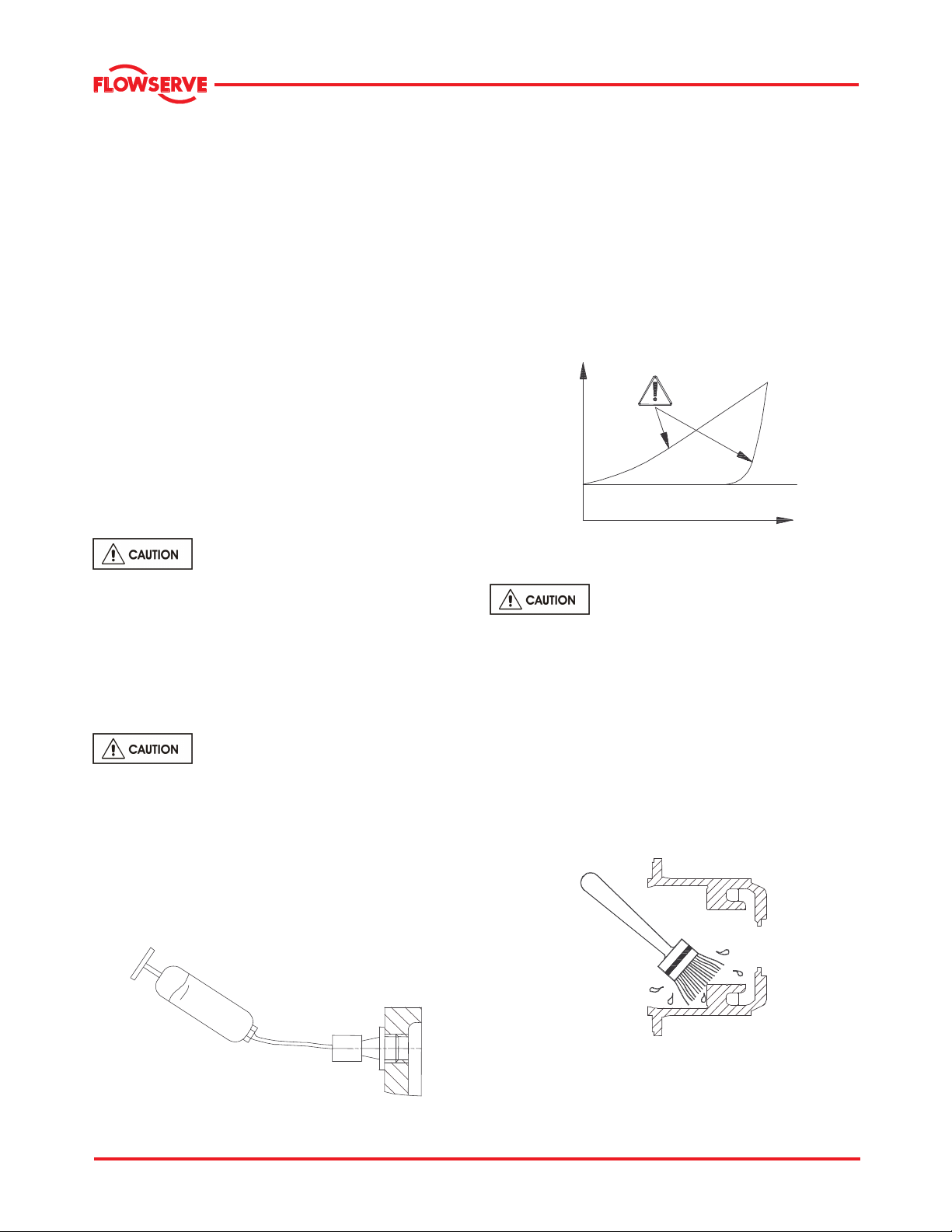
®
MNV & MNZ USER INSTRUCTIONS ENGLISH 71569188 11/04
Check that the sleeve is free of pits, burrs or sharp
edges to prevent cutting or improper sealing of the
rotating O-rings.
6.1.9.3 Installing the seal
Refer to the manufacturer's instructions for seal
installation.
6.1.9.4 Before starting the unit.
Check and make certain that the gland flushing line)
is clean (and also, return line if it is a double seal,
open and free of any obstruction that may interfere
with circulation of clear flushing liquid for the seal.
Before start up bleed all air from the seal cavity. This
is necessary to ensure a clean liquid environment for
effective seal operation
6.1.10 Re-lubrication
Lubricant and bearing temperature analysis can be
useful in optimizing lubricant change intervals. In
general the following is recommended.
6.1.10.1 Oil lubrication
Maintaining the correct oil level is very
important. If a sight glass has been fitted then
regular checks should be made to ensure the level is
maintained at the center of the glass window.
Refer to section 5. for methods of oil fill, oil grade
recommendations and for the schedule and
temperature limits.
6.1.10.2 Grease lubrication
See section 5.2.5 for grease
recommendations. Re-grease via grease nipples
depending on the severity of the application.
a) It is important not to under or over grease the
bearings as this will lead to over heating and
premature failure. Grease lubricated bearing
housings have grease nipples fitted in the
bearing covers.
b) Connect grease gun to the nipple.
c) Press grease into the bearing housing until the
first signs of it appear in the gap between the
housing and shaft, then stop greasing.
d) The maximum allowable operating temperatures
for anti friction bearings will vary from unit to unit,
depending on ambient and fluid temperature.
The rise above ambient should not normally
exceed 55 °C (131 °F) or a combined maximum
of 95 °C (204 °F).
e) A continuously rising temperature or an abrupt
temperature rise indicates a problem. If these
symptoms occur, stop the pump immediately and
investigate the cause.
TIME
6.1.10.3 Grease change
if Kerosene is used to clean the
bearings make sure that the required safety
measures are to be in place while handling this liquid
fuel for cleaning (See Fuel supplier/ manufacturer’s
Material Safety Data Sheets for provided flash and
flame temperatures).
a) Remove the bearing housing from the rotor
assembly.
b) Brush the bearing housing with hot oil (at about
94o to 115oC (200o to 240oF) or other non-toxic
solvent.
c) Clean and flush out the housing with a light
mineral oil.
d) Do not use waste oil to clean the housing.
Page 34 of 47
Page 35

®
MNV & MNZ USER INSTRUCTIONS ENGLISH 71569188 11/04
6.1.10.4 To clean the bearings
a) Wipe off as much grease as possible with a clean
lint-free cloth.
b) Brush bearings with hot oil or non-toxic solvent
80 to 95 oC (180 to 200 oF ) while gently spinning
the outer bearing ring.
c) Spin each roller to ensure that it is clean
6.1.10.5 To remove badly oxidized grease
a) Support the rotor in a vertical position and
immerse the bearing in hot kerosene or a mixture
of alcohol and light mineral solvent.
b) Gently spin the bearing outer ring.
c) Dry and reflush the bearing with clean light oil.
d) It is important not to under or over grease the
bearings as this will lead to over heating and
premature failure. It is recommended that the
bearings be filled with grease using a suitable
spatula. In addition the housings should be no
more than half filled.
6.1.11 Mechanical seals
No adjustment is possible. When leakage reaches
an unacceptable level the seal will need replacement.
6.1.12 Gland packing
The stuffing box split gland can be completely
removed for re-packing or to enable the addition of
extra rings of packing.
The stuffing box is normally supplied with a lantern
ring to enable a clean or pressurized flush to the
center of the packing. If not required, this can be
replaced by an extra 2 rings of packing.
There must always be a small leakage, normally a
minimum of 30~60 drops per minute is required
depending upon the sleeve diameter.
6.2 Spare parts
6.2.1 Ordering of spares
Flowserve keep records of all pumps that have been
supplied. When ordering spares the following
information should be quoted:
a) Pump serial number.
b) Pump size.
c) Part name – taken from section 8.
d) Part number – taken from section 8.
e) Number of parts required.
The pump size and serial number are shown on the
pump nameplate.
To ensure continued satisfactory operation,
replacement parts to the original design specification
should be obtained from Flowserve.
Any change to the original design specification
(modification or use of a non-standard part) will
invalidate the pump’s safety certification.
6.2.2 Service parts
The severity of the condition of service, the extent to
which repairs can be carried out in the field, and the
number of units installed will determine, to a great
extent, the minimum number of service parts that
should be carried in stock at the installation site. It is
suggested, as insurance against delays, that service
parts be purchased at the time the pump order is
placed or as soon after receiving the pump as
possible.
A suggested spare parts list (priced if desired) can be
furnished upon request.
6.2.3 Returning parts
All material returned to the factory must have a
returned material (RM) tag attached. Consult the
nearest Flowserve sales office or OEM factory for
shipping instructions and "RM" tags. Unnecessary
delays are avoided when parts or equipment are
returned to the proper factory using the correct
procedure.
a) When contacting the sales office or factory for
return authorization, list the material to be
returned and the reasons for returning it.
b) On receipt of the "RM" tags, be sure to check the
part name, the part number, the quantity of parts
involved, and the serial number of the equipment.
c) The "RM" tag must accompany the material
shipped. Enclose it in the shipping container or
attach it to the part being returned.
Page 35 of 47
Page 36

®
MNV & MNZ USER INSTRUCTIONS ENGLISH 71569188 11/04
d) In cases where more than one part or box is
returned, individually print or stencil your name,
the part name, and the "RM" tag number on each
part or box. Then attach the "RM" tag to one of
the parts or boxes. This will facilitate quick
identification.
Articles being returned should be carefully packed to
prevent damage from handling or from exposure to
the weather.
6.2.4 Storage of spares
Spares should be stored in a clean dry area away
from vibration. Inspection and re-treatment of
metallic surfaces (if necessary) with preservative is
recommended at 6 monthly intervals.
6.3 Suggested spares and consumable
items
For start up purposes:
1 - complete set of gland packing
1 - shaft sleeves
1 - set of gaskets and seals
(optional: 2 - mechanical seal kits)
For 2 years operation:
1 - set of bearings (line and thrust)
2 - sets of gland packing
2 - shaft sleeves
2 - sets of gaskets and seals
2 - lantern rings
2 - casing wear rings
(optional: 2 - mechanical seals
2 - impeller wear rings)
For 4 years operation:
1 - set of bearings (line and thrust)
2 - sets of gland packing
2 - shaft sleeves
2 - sets of gaskets and seals
2 - lantern rings
2 - casing wear rings
1 - impeller
(optional: 2 - mechanical seals, 2 - impeller wear
rings)
6.4 Tools required
No special tools are needed to maintain this pump.
Most tools are readily available in standard tool kits,
and dependent on pump size:
• Open ended spanners (wrenches)
• Socket spanners (wrenches)
• Allen keys
• Range of screwdrivers
• Soft mallet
For some specialized equipment:
• Bearing induction heater/Oven
• Dial test indicator
• C-spanner (wrench) - for removing shaft nut.
(If difficulties in sourcing are encountered,
consult Flowserve.)
6.5 Fastener torques
The following table is provided as a guide for the
proper assembly of Grade (SAE) 2 fasteners.
Torques are for lubricated threads. Lubricate the
fastener and tapped hole threads and the underside
of the bolt heads and nuts before assembly.
DO NOT lubricate threads that require the
application of Loctite thread locking compound.
Bolt size
mm (in.)
M 6 (1/4) 8 (6)
M 8 (5/16) 16 (12)
M 10 (3/8) 28.5 (21)
M 12 (7/16) 47.5 (35)
M 14 (1/2) 70 (50)
*(9/16) 95 (70)
M 16 (5/8) 135 (100)
M 20 (3/4) 235 (175)
M 24 (7/8) 205 (150)
M 27 (1) 305 (225)
M 30 (1-1/8) 435 (320)
M 33** (1-1/4) 610 (450)
M 36 (1-3/8) 800 (590)
M 39** (1-1/2) 1070 (790)
*
No metric equivalent available
Torque
N-m (lb-ft)
** Nearest size equivalent in metric (non-std)
For assembly of a joint always finger
tighten all nuts or bolts first. Then cross-tighten
evenly in about three equal steps to develop final
torque values.
6.6 Renewal clearances.
As wear takes place between the impeller and casing
ring the overall efficiency of the pump set will
decrease. To maintain optimum efficiency it is
recommended that rings are replaced and the
impeller refurbished. The clearance dimensions
depends on pump size. Contact Flowserve
representative for the service advise.
Page 36 of 47
Page 37

®
MNV & MNZ USER INSTRUCTIONS ENGLISH 71569188 11/04
6.7 Disassembly
Refer to section 1.6, Safety, before dismantling
the pump.
Before dismantling the pump for
overhaul, ensure genuine Flowserve replacement
parts are available. Refer to sectional drawings for
part numbers and their identification.
6.7.1 Preliminary dismantling procedure
a) Isolate motor and lock off electrical supply in
accordance with local regulations.
b) Isolate suction and discharge valves.
c) Remove coupling guards and disconnect the U
shaft.
d) Drain pump casing. Remove any auxiliary piping
if applicable.
6.7.2 Pump dismantling procedure
Care must be exercised in the dismantling operation.
Close the suction and discharge valves and drain
liquid from the casing. For convenience at reassembly, lay out all parts in the order in which they
are removed. Protect all machined faces against
metal to metal contact and corrosion. Proceed as
follows referencing the pump sectional drawing.
a) Disconnect the intermediate shaft section closest
to the pump. If possible, swing the shaft section
out to the side and secure.
b) Unbolt the stuffing box head from the casing.
c) Draw out the rotating assembly complete with the
stuffing box head, bearing housing, impeller, etc.
Exercised care in slinging and handling the unit.
d) Remove the impeller nut set screw and the
impeller nut. The set screw was mounted using
Loctite 271 or equivalent and may require
heating to 200 oC (400 oF) for removal. A
standard square bar will fit the square hole
provided in the impeller nut.
e) Remove the impeller and impeller key.
f) Remove the packing gland. If the pump is
equipped with a mechanical seal unbolt the
gland.
g) Unbolt and remove the bearing frame from
stuffing box head. The packing and seal cage
halves may be removed at this time. Remove
the mechanical seal if so equipped.
h) Remove the shaft sleeve only if necessary; see
Maintenance of Shaft and Shaft Sleeve.
i) Remove pump coupling half. Do not hammer to
remove.
j) Remove the upper and lower outside seal rings.
k) Remove the upper and lower bearing housing
covers with their respective seals. If a bent shaft
is suspected, the shaft should be checked for
runout at this time. The maximum permissible
runout is 0.002" (0.051mm) TIR at the bearing,
coupling, sleeve, and impeller turns.
l) Disengage the thrust bearing lock washer tab
from its locknut. Unscrew the thrust bearing
locknut and remove the lock washer and bearing
washer.
m) Remove the shaft toward the impeller end. The
thrust bearing will be pushed off the shaft by this
movement.
n) For further removal of bearings refer to
Maintenance of Bearings.
Carefully examine all individual parts, important
joints, and all wearing surfaces as the pump and
rotor are dismantled. As a general rule, regardless of
the performance of the unit, bearings and parts
appreciably worn should be renewed if it is not
intended to examine the pump again until the next
overhaul period.
6.7.3 Bearing installation and removal
Anti-friction bearing cones (inner race) are usually
pressed or shrunk onto the shaft. The cups (outer
races) are usually pressed or shrunk into the bearing
housing. When mounting bearings it is important that
the proper fit is maintained.
When a pulling device is used to remove bearings
from the shaft, the pulling jaws or fingers should be
located on the bearing cone. When other parts do
not interfere, the bearing cone may be supported by
a split ring and the shaft pressed out using an arbor
press. The bearing cups can similarly be pulled out
of the housing.
There are two methods for mounting a bearing on the
pump shaft:
a) Heating the bearing to expand the cone and
shrinking it on the shaft.
b) Pressing the bearing onto the shaft.
The method (a) is preferred over the method (b).
Heat the bearing in an oil bath or electric oven to a
uniform temperature of 120 oC (250 oF). When
heated, quickly mount it on the shaft. If the alternate
method is used, apply force by means of an arbor
press; see detail below. Use a tubular sleeve, ring,
or small blocks of equal thickness to apply the force
to the cone (inner race).
Page 37 of 47
Page 38

®
MNV & MNZ USER INSTRUCTIONS ENGLISH 71569188 11/04
In forcing a bearing onto a shaft, be careful that the
cone is never cocked.
Check the position of the bearing on the shaft with a
feeler gauge to ensure it is pressing firmly against the
shaft shoulder.
ARBOR PRESS
SHAFT
BEARING CONE
RING ON
CONE ONLY
a) Mount a dial indicator on the thrust end of the
housing with its arm resting on top of the pump
shaft.
b) With the bearing assembly supported vertically
on the impeller, oscillate the frame to allow the
line bearing rollers to fully seat. If this is not done
false readings will be obtained. Record the dial
indicator reading.
c) Now lift the bearing frame and oscillate the shaft
to allow the thrust bearing rollers to fully seat.
Record the dial indicator reading.
d) The bearing end play is the difference in readings
in items (b) and (c) above. Repeat steps (b) and
(c) above to assure measurement consistency.
e) Once the endplay is set, bend over the closest
lock washer tab into one of the thrust bearing
locknut slots. This will secure the bearing locknut
in place.
Mounting a bearing cone on a shaft using an arbor
press
6.7.4 Bearing end play adjustment
The initial end play will usually be 0.13 to 0.38 mm.
(0.005 to 0.015 in.). Adjust to the recommended end
play shown in section 6.7.5 by tightening the thrust
bearing nut as necessary and repeating the
procedure below to check the end play. If the end
play becomes less than the recommended endplay,
the thrust bearing nut must be loosened and the
thrust bearing cone backed off by pressing if
necessary (due to likelihood of being an interference
fit). DO NOT exceed the static rating of the thrust
bearing if pressing is necessary. The entire rotating
element (bearing frame, stuffing box head, and
impeller) should be assembled before the bearing
endplay is set. The assembly weight is necessary to
properly set the bearing endplay.
Page 38 of 47
Page 39

®
MNV & MNZ USER INSTRUCTIONS ENGLISH 71569188 11/04
6.7.5 Bearing end play
Bearing
Frame
With full tang movement With 1/4 tang movement
4T 0.03-0.10
5T 0.03-0.10
6 0.03-0.10
6A 0.03-0.10
7L 0.03-0.10
7H 0.03-0.10
8L 0.03-0.10
8H
8HA
9H
9HA
Recommended
end play
mm
(in.)
(0.002 - 0.004)
(0.002 - 0.004)
(0.002 - 0.004)
(0.002 - 0.004)
(0.002 - 0.004)
(0.002 - 0.004)
(0.002 - 0.004)
0.03-0.10
(0.002 - 0.004)
0.08-0.16
(0.003 -0.005)
0.08
(0.0033)
0.08
(0.0033)
0.07
(0.0028)
0.07
(0.0028)
0.11
(0.0044)
0.11
(0.0044)
0.11
(0.0044)
0.11
(0.0044)
0.17
(0.0066)
End play adjustment
mm
(in.)
0.02
(0.0008)
0.02
(0.0008)
0.02
(0.0008)
0.02
(0.0008)
0.03
(0.0011)
0.03
(0.0011)
0.03
(0.0011)
0.03
(0.0011)
0.04
(0.0016)
Thrust bearing
static load rating
Kg
(lb.)
2250
(4970)
5580
(12300)
6220
(13700)
8850
(19500)
6560
(14470)
7200
(15880)
10240
(22580)
15950
(35170)
23550
(51920)
6.8 Examination of parts
Used parts must be inspected before
assembly to ensure the pump will subsequently run
properly.
In particular, fault diagnosis is essential to enhance
pump and plant reliability.
6.8.1 Casing, seal housing and impeller
a) Inspect for excessive wear, pitting, corrosion,
erosion or damage and any sealing surface
irregularities.
b) Replace as necessary.
6.8.2 Shaft and sleeve (if fitted)
Replace if grooved, pitted or worn.
6.8.3 Gaskets and O-rings
After dismantling, discard and replace.
6.8.4 Bearings
a) It is recommended that bearings are not re-used
after any removal from the shaft.
b) The plain liquid lubricated bearings may be re-
used if both the bearing bush and bearing sleeve
show no sign of wear, grooving or corrosion
attack. (It is recommended that both the bush
and sleeve are replaced at the same time.)
6.8.5 Bearing isolators, or lip seals (if fitted)
a) The lubricant, bearings and bearing housing
seals are to be inspected for contamination and
damage. If oil bath lubrication is utilised, these
provide useful information on operating
conditions within the bearing housing.
b) If bearing damage is not due to normal wear and
the lubricant contains adverse contaminants, the
cause should be corrected before the pump is
returned to service.
c) Lip seals and bearing isolators should be
inspected for damage but are normally nonwearing parts and can be re-used.
d) Bearing seals are not totally leak free devices.
Oil from these may cause staining adjacent to the
bearings.
Page 39 of 47
Page 40

®
MNV & MNZ USER INSTRUCTIONS ENGLISH 71569188 11/04
6.9 Assembly
To assemble the pump consult the sectional
drawings, see section 8, Parts list and drawings.
Ensure threads, gasket and O-ring mating faces are
clean. Apply thread sealant to non-face sealing pipe
thread fittings.
6.9.1 Bearing housing assembly - Grease
lubricated
a) Be sure the shoulders where the bearings seat,
are free of burrs and contaminants.
b) Mount the grease retainers into their respective
bores [51, 51A]. Prick punch the outer diameter
at two places 180o apart to secure them to the
bearing frame, if necessary. Do not remove the
grease retainers on disassembly unless they are
to be replaced.
c) Mount the bearing cups (outer races) [16,18] into
their respective bearing housing bores (either
chill or press in to install). Be sure the cups seat
against the bearing housing shoulders.
d) Assemble the line bearing cone [16] on the shaft
[6] (heat or press to install). See section 6.7.3 for
details.
e) Install the shaft [6] with the thoroughly grease-
packed line bearing cone fitted, through the
housing and support the assembly vertically
(thrust end up).
f) Heat the thrust-bearing cone to approximately
95 oC (200 oF) and assemble it on the shaft
together with the bearing washer [22B], lock
washer [22A], and locknut [22]. Hand tighten the
nut.
g) Assemble the line bearing inner seal [40A], line
bearing cover [35] and outer seal [40A]. Adjust
the bearing endplay; See Bearing End Play
adjustment in section 6.7.4.
h) Pack the thrust bearing [18] with grease.
i) Install the thrust bearing’s inside seal [49], cover
[37] and outside seal [40].
The impeller set screw and wearing ring
screws are locked in place using Loctite 271 or
equivalent. The shaft sleeve is mounted using
Loctite RC/680 or equivalent. Mating surfaces must
be thoroughly cleaned and dry prior to application of
the adhesive compound.
6.9.1.1 Impeller nut
LOCATION FOR
SQUARE BAR
IMPELLER NUT
SET SCREW
IMPELLER NUT
IMPELLER NUT
FILLET
(2 PLACES 18O°APART)
Grease all the contact seal lips before
installation. Position the outside seals (line and thrust
bearing) with minimum lip contact to the covers.
Excessive lip pressure will result in the seal rings
running hot and premature seal ring failure.
6.9.2 Pump assembly
To assemble the pump, reverse the dismantling
instructions previously described.
a) Follow the bearing housing assembly, wearing
ring, packing, and shaft sleeve assembly
instructions. Torque all assembly bolts and
screws to the recommended torque values listed
in section 6.5.
b) If the unit is equipped with a mechanical seal,
refer to the mechanical seal manufacturer's
instructions for installation.
c) Install the rotating assembly in the casing [1].
d) Check that the impeller [2] turns freely and adjust
the wearing ring gap. See section 6.1.6 for
details.
e) Align the pump with the motor; see Section 4.5.
f) Install the packing and seal cage; see Section
6.1.8.
g) Add lubricant as described in Section 5.2.
Page 40 of 47
Page 41

®
MNV & MNZ USER INSTRUCTIONS ENGLISH 71569188 11/04
7 FAULTS; CAUSES AND REMEDIES
FAULT SYMPTOM
P ump ov e r h eats a n d sei z e s
B earin gs h ave sh o r t lif e
⇓
⇓
P ump vi b r a tes o r i s nois y
⇓
⇓
M echa ni c a l sea l/ g l a n d h as s h o rt l if e
⇓
⇓
M echa ni c a l sea l/ g l a n d l ea k s e xces si v e l y
⇓
⇓
P ump re q u i res e xc e s s ive p ow e r
⇓
⇓
P ump lo s e s prim e a fter s t arti ng
⇓
⇓
I nsuf fi c i e nt d is c h a rge p r e s s ure de v e l oped
⇓
⇓
I nsuf fi c i e nt c ap a c ity d e l i ver ed
⇓
⇓
⇓
⇓
P ump do e s not de l i v er l iq u i d
⇓
⇓
PROBABLE CAUSES POSSIBLE REMEDIES
A. System troubles
Pump not primed.
Pump or suction pipe not completely filled with
liquid or valves not fully open.
Suction lift too high or level too low.
Insufficient margin between suction pressure and
vapour pressure.
Excessive amount of air or gas in liquid. Check and purge pipes and system.
Air or vapour pocket in suction line. Check suction line design for vapour pockets.
Air leaks into suction line. Check suction pipe is airtight.
Air leaks into pump through mechanical seal,
sleeve joints, casing joint or pipe plugs.
Impeller, casing piping partially /fully clogged. Investigate replacing the valve.
Inlet of suction pipe insufficiently submerged. Clean /open valve as required.
Inlet of suction pipe insufficiently submerged. Check out system design.
Speed too low. Consult Flowserve.
Speed too high. Consult Flowserve
Total head of system higher than differential head
of pump.
Total head of system lower than pump design head.
Specific gravity of liquid different from design.
Viscosity of liquid differs from that for which
designed.
Operation at very low capacity. Measure value and check minimum permitted.
Operation at high capacity. Measure value and check maximum permitted.
B. Mechanical troubles
Misalignment due to pipe strain. Check the flange connections and eliminate strains
Improperly designed foundation and/or critical
frequency of the system excited.
Shaft bent. Check shaft runouts are within acceptable values
Rotating part rubbing on stationary part internally. Check and Consult Flowserve, if necessary.
Bearings worn Replace bearings.
Check and fill with liquid completely. Vent and/or
prime.
Check NPSHA>NPSHR, proper submergence, losses
at inlet and fittings.
Check and replace faulty parts. Refer to Seal User
Instructions/Consult Flowserve.
Check system losses. Remedy or Consult
Flowserve.
Check and Consult Flowserve.
Remedy or Consult Flowserve.
Remedy or Consult Flowserve.
using elastic couplings or a method permitted.
Check setting of baseplate: tighten, adjust, grout
base as required. Resonance tests
Consult Flowserve.
Page 41 of 47
Page 42

®
MNV & MNZ USER INSTRUCTIONS ENGLISH 71569188 11/04
FAULT SYMPTOM
P ump ov e r h eats a n d sei z e s
B earin gs h ave sh o r t lif e
⇓
⇓
P ump vi b r a tes o r i s nois y
⇓
⇓
M echa ni c a l sea l/ g l a n d h as s h o rt l if e
⇓
⇓
M echa ni c a l sea l/ g l a n d l ea k s e xces si v e l y
⇓
⇓
Excessive grease in ball bearings. Check method of re-greasing.
P ump re q u i res e xc e s s ive p ow e r
⇓
⇓
P ump lo s e s prim e a fter s t arti ng
⇓
⇓
I nsuf fi c i e nt d is c h a rge p r e s s ure de v e l oped
⇓
⇓
I nsuf fi c i e nt c ap a c ity d e l i ver ed
⇓
⇓
P ump do e s not de l i v er l iq u i d
⇓
⇓
⇓
⇓
PROBABLE CAUSES POSSIBLE REMEDIES
Leakage under sleeve due to joint failure. Replace joint and check for damage.
Shaft sleeve worn or scored or running off centre. Check and renew defective parts.
Impeller out of balance resulting in vibration.
Abrasive solids in liquid pumped.
Wearing ring surfaces worn. Replace worn wear ring/surfaces.
Impeller damaged or eroded. Replace or consult Flowserve for improved material
Mechanical seal/packing improperly installed. Check alignment of faces or damaged parts and
Incorrect type of mechanical seal/packing for
operating conditions.
Shaft running off centre because of worn bearings
or misalignment.
Internal misalignment of parts preventing seal ring
and seat from mating properly.
Mechanical seal /packing was run dry. Check mechanical seal/gland condition and source
Internal misalignment due to improper repairs
causing impeller to rub.
Excessive thrust caused by a mechanical failure
inside the pump.
Lack of lubrication for bearings. Check hours run since last change of lubricant, the
Improper installation of bearings (damage during
assembly, incorrect assembly, wrong type of
bearing etc).
Damaged bearings due to contamination. Check contamination source and replace damaged
selection.
assembly method used.
consult Flowserve.
Check misalignment and correct if necessary. If
alignment is satisfactory, check the bearings for
excessive wear.
Check and consult Flowserve.
of dry running and repair.
Check method of assembly, possible damage or
state of cleanliness during assembly.
Remedy or consult Flowserve, if necessary.
Check wear condition of impeller, its clearances and
liquid passages.
schedule and its basis.
Check method of assembly, possible damage or
state of cleanliness during assembly and type of
bearing used. Remedy or consult Flowserve, if
necessary.
bearings.
C. Motor electrical problems
Wrong direction of rotation. Reverse 2 phases at motor terminal box.
Motor running on 2 phases only. Check supply and fuses.
Motor running too slow. Check motor terminal box connections and voltage.
Page 42 of 47
Page 43

®
MNV & MNZ USER INSTRUCTIONS ENGLISH 71569188 11/04
8 PARTS LIST AND DRAWINGS
8.1 MNV cross section and parts list
(Typical- Grease filled)
The sectional drawing provided in this section are typical representation of MNV pump with grease
lubrication. The details shown here may not reflect the specifics of the pump that has been purchased or
ordered. You may purchase order specific cross sectional drawings separately. Please contact Flowserve for
pricing and ordering information on such documentation.
Page 43 of 47
Page 44

®
MNV & MNZ USER INSTRUCTIONS ENGLISH 71569188 11/04
8.1.1 Parts list MNV (See section 8.1 for details)
Ref
No
1 1 Casing
9 1 Suction head
11 1 Stuffing box head
13 5 RINGS Packing
17 1 Split gland
25 1 Suction head wearing ring
29 1 Seal cage split
35 1 Line bearing cover
37 1 Thrust bearing cover
51 Grease retainer- out board
51A 1 Grease retainer inboard
59 1 Casing hand hole cover
59A 1 Suction head hand-hole cover
67 1 SET Adjusting shims
73 2 Casing gasket
73A 1 Casing hand hole cover gasket
73B 1 Suction head hand hole cover gasket
73C 1 Line bearing cover gasket
73D 1 Thrust bearing cover gasket
99 1 Bearing frame
99A 2 Adjusting bolt
125 2 Grease fitting
No
required
STATIONARY PARTS
Description
Ref No No
required
2 1 Impeller
6 1 Pump shaft
8 1 Impeller wearing ring
14 1 Shaft sleeve
16 1 Line bearing
18 1 Thrust bearing
22 1 Bearing locknut
22A 1 Bearing lock-washer
22B 1 Bearing washer
24 1 Impeller nut
40 2 Seal ring (thrust)
40A 2 Seal ring (Line)
ROTATING PARTS
Description
Page 44 of 47
Page 45
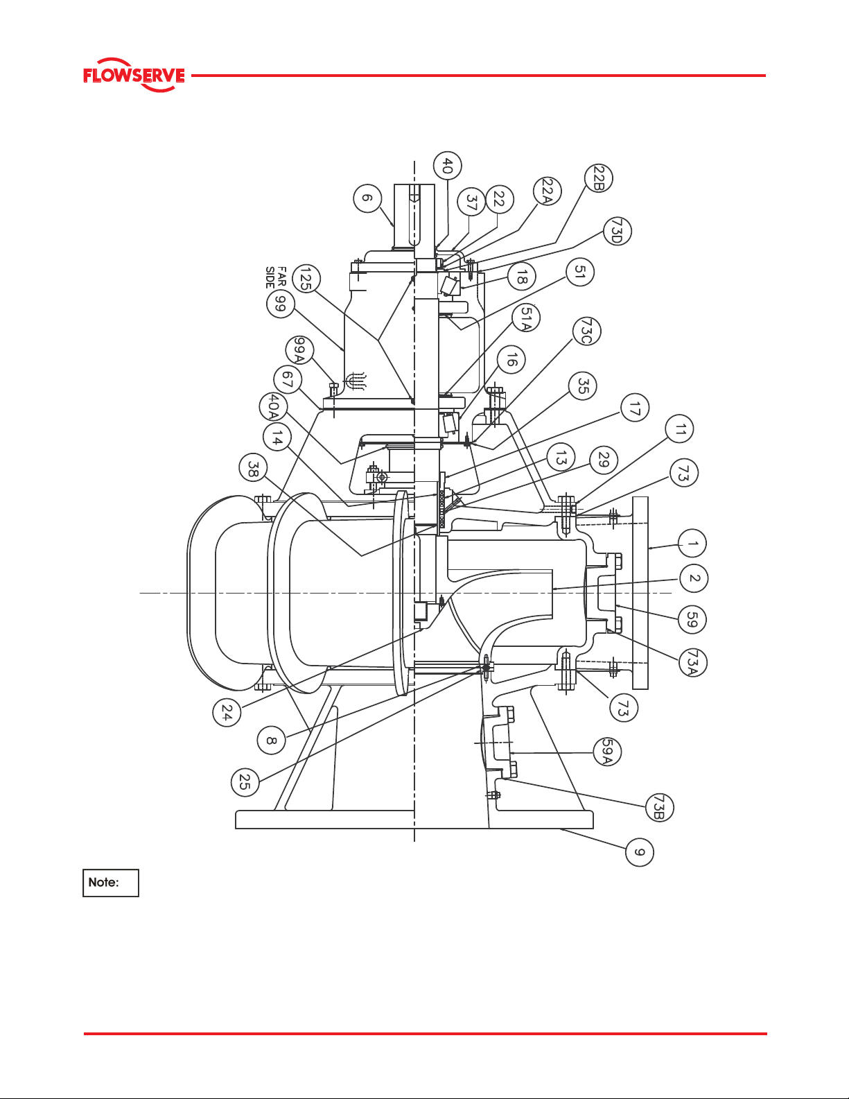
®
MNV & MNZ USER INSTRUCTIONS ENGLISH 71569188 11/04
8.2 MNZ cross section and parts list
(Typical- Grease filled)
The sectional drawing provided in this section are typical representation of MNV pump with grease
lubrication. The details shown here may not reflect the specifics of the pump that has been purchased or
ordered. You may purchase order specific cross sectional drawings separately. Please contact Flowserve for
pricing and ordering information on such documentation.
Page 45 of 47
Page 46

®
MNV & MNZ USER INSTRUCTIONS ENGLISH 71569188 11/04
8.2.1 MNZ parts list (See section 8.2 for details)
Ref No No
required
1 1 Casing
9 1 Suction head
11 1 Stuffing box head
13 5 rings Packing
17 1 Split gland
25 1 Suction head wearing ring
29 1 Seal cage split
35 1 Line bearing cover
37 1 Thrust bearing cover
51 Grease retainer- out board
51A 1 Grease retainer inboard
59 1 Casing hand hole cover
59A 1 Suction head hand-hole cover
67 1 Set Adjusting shims
73 2 Casing gasket
73A 1 Casing hand hole cover gasket
73B 1 Suction head hand hole cover gasket
73C 1 Line bearing cover gasket
73D 1 Thrust bearing cover gasket
99 1 Bearing frame
99A 2 Adjusting bolt
125 2 Grease fitting
STATIONARY PARTS
Description
Ref No No
required
2 1 Impeller
6 1 Pump shaft
8 1 Impeller wearing ring
14 1 Shaft sleeve
16 1 Line bearing
18 1 Thrust bearing
22 1 Bearing locknut
22A 1 Bearing lock washer
22B 1 Bearing washer
24 1 Impeller nut
38 1 Shaft sleeve O ring
40 2 Seal ring (thrust)
40A 2 Seal ring (Line)
ROTATING PARTS
Description
8.3 General arrangement drawing
The typical general arrangement drawing and any
specific drawings required by the contract will be sent
to the Purchaser separately unless the contract
specifically calls for these to be included into the
User Instructions. If these drawings are sent
separately, the Purchaser must retain them with the
User Instructions.
9 CERTIFICATION
Certificates determined from the Contract
requirements are provided with these Instructions
where applicable. Examples are certificates for CE
marking, ATEX marking etc. If required, copies of
other certificates sent separately to the Purchaser
should be obtained from the Purchaser for retention
with these User Instructions.
10 OTHER RELEVANT
DOCUMENTATION AND MANUALS
10.1 Supplementary user instructions
Supplementary instructions such as for a driver,
instrumentation, controller, seals, sealant system etc
are provided as separate documents in their original
format. If further copies of these are required they
should be obtained from the supplier for retention
with these User Instructions.
10.2 Change notes
If any changes, agreed with Flowserve Pump
Division, are made to the product after its supply, a
record of the details should be maintained with these
Use Instructions.
Page 46 of 47
Page 47

®
MNV & MNZ USER INSTRUCTIONS ENGLISH 71569188 11/04
FLOWSERVE
REGIONAL SALES OFFICES:
USA and Canada
Flowserve Corporation (Head Quarters)
5215 North O’ Connor Blvd. Suite 2300
Irving, TX 75039, USA
Tel +1 972 443 6500
Toll free 800 728 PUMP (7867)
Fax +1 972 443 6800
Europe, Middle East & Africa
Flowserve Limited (Pump Division)
Harley House, 94 Hare Lane
Claygate, Esher, Surrey KT10 0RB
United Kingdom
Tel +44 (0)1372 463 700
Fax +44 (0)1372 460 190
Visit our web site at: www.flowserve.com
Your Flowserve factory contact:
Flowserve Pump Division
5310 Taneytown Pike, PO Box 91
Taneytown, MD 21787-0091, USA
Customer Service-PH: +1 (410) 756 2602
Customer Service FAX: +1 (410) 756 2615
Parts inquiry/Order PH: +1 (800) 526 3569
Latin America & Caribbean
Flowserve Corporation (Pump Division)
6840 Wynnwood Lane
Houston, Texas 7708, USA
Tel +1 713 803 4434
Fax +1 713 803 4497
Asia Pacific
Flowserve Pte Ltd (Pump Division)
200 Pandan Loop, # 06-03/04
Pantech 21, Singapore 128388
Tel +65 775 3003
Fax +65 779 4607
Your local Flowserve representative:
To find your local Flowserve representative, please
use the Sales Support Locator System found at
www.flowserve.com
Page 47 of 47
 Loading...