

Page 1

GESTRA
GESTRA Steam Systems
MK 45
MK 45A
Installation Instructions 810348-06Steam Traps
Steam Traps
MK 45, MK 45A
1
Page 2

Contents
Page
Important Notes
Usage for the intended purpose ............................................................................................................ 7
Safety note ........................................................................................................................................... 7
Danger ................................................................................................................................................. 7
Rating pursuant to article 9 of the PED ................................................................................................. 7
Explanatory Notes
Scope of supply...................................................................................................................................... 8
Description............................................................................................................................................. 8
Function ................................................................................................................................................. 8
Technical data MK 45 ............................................................................................................................ 9
Technical data MK 45A ........................................................................................................................ 10
Name plate MK 45 ............................................................................................................................... 11
Name plate MK 45A ............................................................................................................................. 11
Installation
MK 45, MK 45A .................................................................................................................................... 12
Design with flanges.............................................................................................................................. 12
Design with screwed-sockets ............................................................................................................. 12
Design with socket-weld ends ............................................................................................................ 13
Design with butt-weld ends................................................................................................................. 13
Check capsule ....................................................................................................................................... 5
Heat treatment of welds ....................................................................................................................... 13
Maintenance
Check steam trap ................................................................................................................................. 13
Check capsule ....................................................................................................................................... 5
Clean / exchange capsule and nozzle seat ........................................................................................... 14
Clean / exchange strainer..................................................................................................................... 14
Torques................................................................................................................................................ 15
Spare Parts
Spare parts list ..................................................................................................................................... 15
2
Page 3
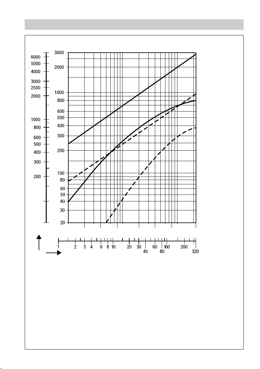
Capacity Chart
[lb/h]
Capacity
[kg/h]
0.1 0.3 0.6 1 3 6 10
0.2 0.4 0.8 2 4 8 22
1
2
3
4
[bar]
[psi]
Fig. 1
∆PMX
Max. flowrate of cold condensate
11
1
11
for MK 45-2, MK 45A-2.
Max. flowrate of cold condensate
22
2
22
for MK 45-1, MK 45A-1.
Max. flowrate of hot condensate
33
3
33
for MK 45-2, MK 45A-2.
Max. flowrate of hot condensate
44
4
44
for MK 45-1, MK 45A-1.
3
Page 4
Design
A
B
C
D
E
F
G
H
o o
p
I
2
2
p
J
K
L
Fig. 2
4
Page 5
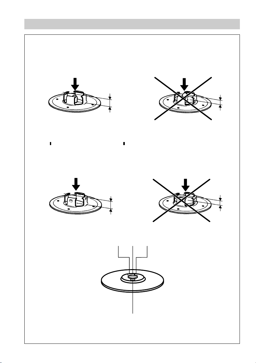
Checking of Capsule
Capsule o for nozzle insert with tandem seat p: 5 N 1, 5 U 1
Capsule intact Capsule defective
≥ 3.2 mm
Capsule o for nozzle insert with single seat p: 5 N 2, 5 U 2
2
2
Capsule intact Capsule defective
≥ 4.4 mm
M N O
≤ 2.6 mm
≤ 3.8 mm
Fig. 3
P
5
Page 6

Key
Hexagon-head screw M 10x 25
A
Name plate
B
Cover
C
Spring
D
Capsule
E
Capsule for tandem seat
o
2
o
Capsule for single seat
Nozzle insert with non-return valve action
F
p Nozzle insert with tandem seat
2
p
Nozzle insert with single seat
Bush (interference-fitted, cannot be replaced)
G
Gasket 40 x 48 x 2
H
Body
I
Strainer
J
Plug gasket A 24x 29
K
Plug M 24x1.5
L
Code number of pressure rating
M
5= ∆p 22 bar
Code letter of opening temperature
N
N = Standard, ∆t appox. 10 K
U = Undercooling, ∆t approx. 30 K
Code number of capacity
O
1 = Low capacity
2 = High capacity
Manufacturing code number
P
6
Page 7

Important Notes
Usage for the intended purpose
Use steam traps MK 45, MK 45A only for the discharge of condensed water or for air venting from
steam spaces.
Use this equipment only for the discharge of condensate from steam lines within the specified
pressure and temperature ratings and check corrosion resistance and chemical suitability for the
application in question.
Safety Notes
Installation must only be performed by qualified staff.
Qualified staff are those persons who – through adequate training in engineering, the use and
application of equipment in accordance with regulations concerning steam systems, and first aid &
accident prevention – have achieved a recognised level of competence appropriate to the installation
and commissioning of this device.
Danger
The steam trap is under pressure during operation.
When loosening flanged connections, plugs or the regulator, hot water and/or steam
may escape. This presents the risk of severe scalding.
Installation and maintenance work should only be carried out when the system is
depressurized: isolate the trap from both upstream and downstream pressure.
The trap becomes hot during operation.
This presents the danger of severe burns to hands and arms. Installation and
maintenance work should only be carried out when the system is cold.
Sharp edges on internal parts present a danger of cuts to hands. Always wear industrial
gloves for installation and maintenance work.
Conformity with EC Pressure Equipment Directive No. 97/23
The equipment has been checked and tested by us and is excluded from the scope of the Directive
(Article 3, Section 3). The equipment is not entitled to bear the CE marking.
7
Page 8

Explanatory Notes
Scope of Supply
MK45
1 Steam trap MK 45
1 Installation manual
MK 45A
1 Steam trap MK 45 A
1 Installation manual
Description
Thermostatic steam trap with corrosion-resistant thermostatic capsule unaffected by waterhammer.
Integral Y-type strainer and non-return valve. Asbestos-free cover gasket (graphite/CrNi). Installation in
any position.
The traps with standard capsule “N” discharge condensate with virtually no banking-up, the traps with
special capsule “U” with an undercooling of approx. 30 K (degC).
■
MK 45-1 with tandem seat (double sealing)
Particularly suitable for low condensate flowrates.
Optionally either with standard capsule “5 N 1” or
undercooling capsule “5 U 1”.
■
MK 45-2 with single seat
For larger condensate flowrates.
Optionally either with standard capsule “5 N 2” or
undercooling capsule “5 U 2”.
■
MK 45A-1 with tandem seat (double sealing)
Particularly suitable for low condensate flowrates.
Optionally either with standard capsule “5 N 1” or
undercooling capsule “5 U 1”.
■
MK 45A-2 with single seat
For larger condensate flowrates.
Optionally either with standard capsule “5 N 2” or
undercooling capsule “5 U 2”.
Function
The MK 45... is a thermostatic steam trap with membrane regulator. The capsule is filled with a liquid
which boils at a temperature a few degrees lower than water. As long as condensate flows through the
steam trap the liquid in the capsule is completely condensed due to the low ambient temperature. The
pressure inside the capsule is lower than the surrounding pressure (service pressure) and the
membrane with the valve disc is pushed in the opening direction. As the condensate temperature
approaches steam temperature, the liquid filling of the capsule starts to boil and evaporate. The
pressure in the capsule rises and the membrane with the valve disc is moved in the closing direction.
Automatic air-venting is provided both, during start-up and during normal operation. The correct
functioning of the MK 45 is neither affected by fluctuations in the upstream pressure nor by back
pressure.The MK 45 can also be used for thermal air venting.
8
Page 9

Explanatory Notes – continued –
Technical Data MK 45
seiresT-p 0E3puorglairetam,1-2901NEot.cca
lairetaM 501AMTSA/)]8.22C[HG052P(0640.1
)ND(eziS52,02,51
noitcennoC 003ssalCEMSA,04NPNIDsegnalF
AMPerusserpecivreS
AMTerutarepmetdetaleR
seiresT-p 1.1puorglairetam,051ssalC,43.61BEMSAot.cca
lairetaM 501AMTSA/)]8.22C[HG052P(0640.1
)ND(eziS52,02,51
noitcennoC051ssalCEMSAsegnalF
AMPerusserpecivreS
AMTerutarepmetdetaleR
04NP54KMsgnitaRerutarepmeT/erusserP
]grab[
]gisp[
]C°[
]F°[
0.04
085
05otpu01–
221otpu41
2.03
634
002
293
8.52
073
003
275
0.42
843
053
266
1.32
533
004
257
051ssalC54KMsgnitaRerutarepmeT/erusserP
]grab[
]gisp[
]C°[
]F°[
7.91
782
02
86
41
302
002
293
2.01
841
003
275
4.8
121
053
266
6.5
18
524
797
1)2
erusserplaitnereffidelbissimdA
)
erusserplaitnereffid.xaM ∆ XMP
1
) Observe pressure/temperature ratings!
2
) Inlet pressure minus outlet pressure
54KMslairetaMNEMTSA
ydoB)0640.1(HG052P501A
revoC)0640.1(HG052P501A
swercsydoB)5227.1(4oMrC247B391A
eluspaccitatsomrehTyolletsaH
slanretnirehtOleetssselniats
teksagydoBiNrC/etihparg
]gisp023[grab22
9
Page 10

Explanatory Notes – continued –
Technical Data MK 45A (Stainless Steel Design)
seiresT-p 0E31puorglairetam1-2901NEot.cca
lairetaM L613F-281AMTSA/)22171oMiNrC2X(4044.1
)ND(eziS52,02,51
noitcennoC 003ssalCEMSA,04NPNIDsegnalF
AMPerusserpecivreS
AMTerutarepmetdetaleR
seiresT-p 3.2puorglairetam,051ssalC,43.61BEMSAot.cca
lairetaM L613F-281AMTSA/)22171oMiNrC2X(4044.1
)ND(eziS52,02,51
noitcennoC051ssalCEMSAsegnalF
AMPerusserpecivreS
AMTerutarepmetdetaleR
]grab[
]gisp[
]C°[
]F°[
]grab[
]gisp[
]C°[
]F°[
04NPA54KMsgnitaRerutarepmeT/erusserP
0.04
085
02
86
0.92
6.024
002
293
0.52
6.263
003
275
0.42
843
053
266
0.42
843
004
257
051ssalCA54KMsgnitaRerutarepmeT/erusserP
9.51
6.032
02
86
1.11
161
002
293
7.9
6.041
003
275
4.8
121
053
266
6.5
18
524
797
1)2
erusserplaitnereffidelbissimdA
)
erusserplaitnereffid.xaM ∆ XMP
1
) Observe pressure/temperature ratings!
2
) Inlet pressure minus outlet pressure
A54KMslairetaMNEMTSA
ydoB)22171oMiNrC2X(4044.1L613F-281A
revoC)22171oMiNrC2X(4044.1L613F-281A
swercsydoB07-2A8B391A
eluspaccitatsomrehTyolletsaH
slanretnirehtOleetssselniats
teksagydoBiNrC/etihparg
10
]gisp023[grab22
Page 11

Explanatory Notes – continued –
Name Plate MK 45
Capacity rating 1
Low flowrate
MK45-1 MK45-2
Thermostatic
capsule
5N1
U
5U1
MADE BY GESTRA
Fig. 4 Fig. 5
Name Plate MK 45 A
Capacity rating 1
Low flowrate
Thermostatic
capsule
5N1
U
5U1
Fig. 6 Fig. 7
Capacity rating 2
High flowrate
MADE BY GESTRA
Capacity rating 2
High flowrate
Thermostatic
capsule
5N2
U
5U2
Thermostatic
capsule
5N2
U
5U2
11
Page 12

Installation
MK45, MK 45A
The steam traps MK 45, MK 45A can be installed in any position. In the case of a horizontal installation,
make sure that the cover is at the top.
Flanged Traps
1. Observe correct position of installation.
2. Observe direction of flow. The flow arrow is on the trap body.
3. Consider space required for opening trap. When the trap is installed a minimum space of 30 mm
is required for removing cover C.
4. Remove plastic plugs. They are only used as transit protection.
5. Clean seating surfaces of both flanges.
6. Install steam trap.
Screwed-Socket Traps
1. Observe correct position of installation.
2. Observe direction of flow. The flow arrow is on the trap body.
3. Consider space required for opening trap. When the trap is installed a minimum space of 30 mm
is required for removing the cover C.
4. Remove plastic plugs. They are only used as transit protection.
5. Clean thread of screwed sockets.
6. Install steam trap.
Socket-Weld Traps
1. Observe correct position of installation.
2. Observe direction of flow. The flow arrow is on the trap body.
3. Consider space required for opening trap. When the trap is installed a minimum space of 30 mm
is required for removing the cover C.
4. Remove plastic plugs. They are only used as transit protection.
5. Clean thermostatic capsule as described under Maintenance.
6. Clean socket-weld ends.
7. Apply arc welding processes 111 and 141 in accordance with DIN EN 24053.
12
Page 13

Installation – continued –
Butt-Weld Traps
1. Observe correct position of installation.
2. Observe direction of flow. The flow arrow is on the trap body.
3. Consider space required for opening trap. When the trap is installed a minimum space of 30 mm
is required for removing the cover C.
4. Remove plastic plugs. They are only used as transit protection.
5. Clean thermostatic capsule as described under Maintenance.
6. Clean butt-weld ends.
7. Apply arc welding processes 111 and 141 in accordance with DIN EN 24053 or gas welding
process 3 to DIN EN 24063.
Attention
■
Only qualified welders certified e. g. according to DIN EN 287 may weld the steam
trap into pressurized lines.
■
Do not insulate steam trap.
Heat treatment of welds
A subsequent heat treatment of the welds is not required.
Maintenance
GESTRA steam trap MK 45... does not require any special maintenance. However, if used in new
installations which have not been rinsed it may be necessary to check and clean the trap.
Check steam trap
You can check the steam trap MK 45... for steam loss during operation using the ultrasonic measuring
unit VAPOPHONE
Should you detect any loss of live steam clean the trap and/or replace the capsule.
®
or the test unit TRAPtest®.
13
Page 14

Maintenance – continued –
Clean/exchange capsule and nozzle insert
1. Observe note “Danger” on page 7.
2. Undo body screws A. Remove cover C from the body I.
3. Remove and clean capsule E. Unscrew nozzle insert F.
4. Replace capsule E in case of visible signs of wear or damage.
5. Clean body, internals and all gasket surfaces.
6. Apply heat-resistant lubricant to all threads and the seating surfaces of the nozzle insert and
the cover (use for instance WINIX
7. Screw in nozzle insert and tighten with a torque of 90 Nm.
8. Position capsule E onto the nozzle insert F and press evenly, such that the capsule snaps
into place.
9. Replace gasket H if there are visual signs of damage. Use the same cover C.
Always replace gasket H when using a new cover C or the cover of another steam trap.
10. Put cover onto the body. Tighten hexagon-head screws A alternately and in
several steps to a torque of 25 Nm.
Tools
■
Spanner A.F.16 mm to DIN 3113, form B
■
Spanner A.F. 22 mm to DIN 3113, form B
■
Torque spanner 20 – 120 Nm to DIN ISO 6789
®
2150).
Clean/exchange strainer
1. Observe note “Danger” on page 7.
2. Unscrew sealing plug L and remove strainer J.
3. Clean strainer, sealing plug and gasket seats.
4. Exchange strainer and sealing in case of visible signs of wear or damage.
5. Exchange gasket K if damaged.
6. Apply heat-resistant lubricant to the thread of the sealing plug (use for instance WINIX
®
2150).
7. Install sealing plug L with gasket K and strainer J. Tighten sealing plug with a torque of 120 Nm.
Tools
■
Spanner A. F. 30 mm to DIN 3113, form B
■
Torque spanner 20 – 120 Nm to DIN ISO 6789
WINIX® 2150 is a registered trademark of WINIX GmbH, Norderstedt
14
Page 15

Maintenance – continued –
Torques
Item Designation Torque [Nm]
F
A
L
All torques are based at 20 °C room temperature.
Nozzle insert 90
Body screws 25
Sealing plug 120
Spare Parts
Spare Parts List
Item
Designation
Membrane regulator, complete 5N1
opH
Membrane regulator, complete 5U1
Membrane regulator, complete 5N2
2o2
opH
p
KJL
Membrane regulator, complete 5U2
Strainer set, complete
Thermostatic capsule 5N1
o
Thermostatic capsule 5U1
MK 45-1
MK 45A-1
375 109
375 111
375 113
375 382
376165
376166
Stock code
1
)
1
)
MK 45-2
MK 45 A-2
375 110
375 112
375 113
375 382
Thermostatic capsule 5N2
2
o
o
H
K
1
) Packaged 10 per box. Contact your local dealer for smaller quantities.
2
) Minimum purchasing quantity 50 pcs. Contact your local dealer for smaller quantities.
Thermostatic capsule 5U2
Cover gasket2) 40 x 48 x 2, graphite
2
Plug gasket
) A 24 x29, stainless steel
375 159 375159
375 162 375162
376 167
376 168
1
)
1
)
15
Page 16

Agencies all over the world
www.gestra.de
GESTRA
España
GESTRA ESPAÑOLA S.A.
Luis Cabrera, 86-88
E-28002 Madrid
Tel. 003491 /51 52032
Fax 00 34 91 /41 36 747; 51 52 036
E-mail: aromero@flowserve.com
Great Britain
Flowserve Flow Control (UK) Ltd.
Burrel Road, Haywards Heath
West Sussex RH 16 1TL
Tel. 00 44 14 44 / 31 44 00
Fax 00 44 14 44 / 31 45 57
E-mail: gestraukinfo@flowserve.com
Italia
Flowserve S.p.A.
Flow Control Division
Via Prealpi, 30
l-20032 Cormano (MI)
Tel. 003902 /66 32 51
Fax 00 39 02/66 32 55 60
E-mail: infoitaly@flowserve.com
Polska
GESTRA POLONIA Spolka z.o.o.
Ul. Schuberta 104
PL - 80-172 Gdansk
Tel. 00 48 58 /306 10 -02 od 10
Fax 00 48 58 /306 33 00
E-mail: gestra@gestra.pl
Portugal
Flowserve Portuguesa, Lda.
Av. Dr. Antunes Guimarães, 1159
Porto 4100-082
Tel. 0035122/619 87 70
Fax 0035122/6107575
E-mail: jtavares@flowserve.com
USA
Flowserve DALCO Steam Products
2601 Grassland Drive
Louisville, KY 40299
Tel.: 00 15 02 / 4 95 01 54, 4 95 17 88
Fax: 00 15 02 / 4 95 16 08
E-Mail: dgoodwin@flowserve.com
GESTRA AG
Postfach 10 54 60, D-28054 Bremen
Münchener Str. 77, D-28215 Bremen
Telefon +49 (0) 421 35 03- 0
Telefax +49 (0) 421 35 03 - 393
E-Mail gestra.ag@flowserve.com
Internet www.gestra.de
810348-06/105cm · © 1999 GESTRA AG · Bremen · Printed in Germany
16
 Loading...