

Page 1
GESTRA
GESTRA Steam Systems
MK 35/2S
MK 35/2S3
Installation Instructions 810740-01
Steam Traps
MK 35/2S, MK 35/2S3
t
1
Page 2
Contents
Page
Important Notes
Usage for the intended purpose...................................................................................... 8
Safety note ......................................................................................................................8
Danger ............................................................................................................................8
Rating pursuant to article 9 of the PED...........................................................................8
Explanatory Notes
Scope of supply ..............................................................................................................9
Description ......................................................................................................................9
Function ..........................................................................................................................9
Technical data ......................................................................................................... 9 10
Corrosion resistance ..................................................................................................... 11
Sizing ............................................................................................................................11
Name plate / marking ....................................................................................................11
Installation
MK 35............................................................................................................................12
Design with flanges .......................................................................................................12
Design with screwed-sockets ........................................................................................12
Design with socket-weld ends .......................................................................................12
Design with butt-weld ends ...........................................................................................13
Heat treatment of welds ................................................................................................13
Commissioning
MK 35............................................................................................................................13
Operation
MK 35............................................................................................................................13
Maintenance
Checking steam trap .....................................................................................................14
Cleaning / exchanging capsule and nozzle seat ...........................................................14
Cleaning / exchanging strainer ......................................................................................14
Torques ......................................................................................................................... 15
Spare Parts
Spare parts list ..............................................................................................................15
2
Page 3
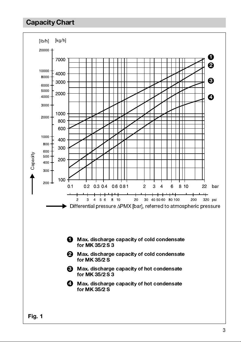
Capacity Chart
[kg/h]
[lb/h]
Capacity
1
2
3
4
Fig. 1
Differential pressure ΔPMX [bar], referred to atmospheric pressure
1
Max. discharge capacity of cold condensate
for MK 35/2 S 3
2
Max. discharge capacity of cold condensate
for MK 35/2 S
Max. discharge capacity of hot condensate
3
for MK 35/2 S 3
4
Max. discharge capacity of hot condensate
for MK 35/2 S
3
Page 4
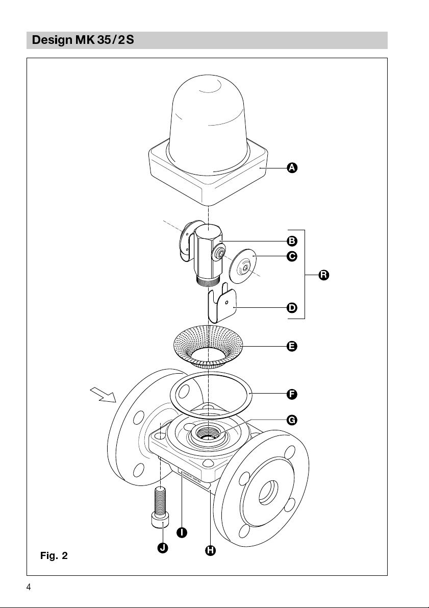
Design MK 35/2S
A
B
C
R
D
4
Fig. 2
E
F
G
I
J
H
Page 5
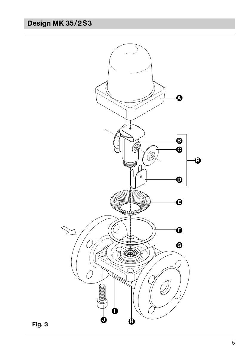
Design MK 35/2S3
A
B
C
R
D
Fig. 3
E
F
G
I
J
H
5
Page 6

Checking Capsule
Thermostatic capsule C for flat seat nozzle support:
Capsule intact
Fig. 4
≥
4.4 mm
Capsule defective
Fig. 5
MLK
5H2
≤
3.8 mm
Fig. 6
6
N
Page 7

Key
A
Cover
B
Capsule holder
R
C
Capsule 5H 2
Fixing clamp
D
Strainer
E
Gasket 67 x 77 x 1
F
G
Bush (interference fit, not a spare part)
H
Body
Name plate
I
Socket-head cap screw M 10 x 30, made of 1.7225/B7 to DIN 912
J
K
Differential pressure rating
5 = Δ
p 22 bar
Regulator
L
Inlet temperature rating
H = Δ
t approx. 4-5 K
M
Capacity rating
2
= large flowrate
N
Manufacturing code number
7
Page 8

Important Notes
Usage for the intended purpose
Use steam traps MK 35/2 S and MK 35/2 S 3 only for the discharge of condensed
water or for air venting from steam spaces.
Use this equipment only within the specified pressure and temperature ratings
and check corrosion resistance and chemical suitability for the application in
question.
Safety note
Installation must only be performed by qualified staff.
Qualified staff are those persons who through adequate training in engineering,
the use and application of equipment in accordance with regulations concerning
steam systems, and first aid & accident prevention have achieved a recognised
level of competence appropriate to the installation and commissioning of this
device.
Danger
The steam trap is under pressure during operation.
When loosening flanged connections, plugs or the thermostatic capsule,
hot water and/or steam may escape. This presents the risk of severe
burns to the whole body.
Installation and maintenance work should only be carried out when the
system is depressurized: isolate the trap from both upstream and
downstream pressure.
The trap becomes hot during operation.
This presents the danger of severe burns to hands and arms. Installation
and maintenance work should only be carried out when the system is
cold.
Sharp edges on internal parts present a danger of cuts to hands. Always
wear industrial gloves for installation and maintenance work.
Rating pursuant to article 9 of the PED1)
The equipment has been checked and tested by the manufacturer. These steam
traps do not fall within the scope of the EC Pressure Equipment Directive (PED)
97-23 (exclusion acc. to Section 3.3) and must
8
not
bear the CE marking.
Page 9

Explanatory Notes
Scope of supply
MK 35/2S
1 Steam trap MK 35/2S
1 Installation manual
MK 35/2S3
1 Steam trap MK 35/2S3
1 Installation manual
Description
Thermostatic steam trap with corrosion resistant thermostatic capsule (membrane
regulator). Integral strainer, asbestos-free cover gasket (graphite). Installation in any
position.
The thermostatic capsule H discharges the condensate with virtually no banking up.
n
MK 35/2 S with single seat
With
two
thermostatic capsules 5H2. For large condensate flowrates up to
e. g. 1100 kg/h at Δp = 5 bar.
n
MK 35/2 S 3 with single seat
With
three
thermostatic capsules 5H2. For large condensate flowrates up to
e. g. 1700 kg/h at Δp = 5 bar.
Function
The MK 35... is a multi-capsule high-capacity steam trap with two or three capsules.
The capsule is filled with a liquid which boils at a temperature a few degrees lower
than water. As long as condensate flows through the steam trap the liquid in the
capsule is completely condensed due to the low ambient temperature. The pressure
inside the capsule is lower than the surrounding pressure (service pressure) and the
membrane with the valve disc is pushed in the opening direction. As the condensate
temperature approaches steam temperature, the liquid filling of the capsule starts to
boil and evaporate. The pressure in the capsule rises and the membrane with the
valve disc is moved in the closing direction.
Automatic air-venting is provided both, during start-up and during normal operation.
The correct functioning of the MK 35... is neither affected by fluctuations in the
upstream pressure nor by back pressure. The MK 35... can also be used for thermal
air venting.
.
Technical Data
Pressure/Temperature Ratings PN 40
Body material 1.0460 (P250GH / C22.8) / ASTM A105
Nominal size (DN) 25
Connection Flanged PN 40, EN 1092-1, WG 3E0
Max. allowable pressure PMA
Inlet temperature TMA
[barg] 40 30.2 25.8 23.1
[psig] 580 437 370 335
[°C] 20 200 300 400
[°F] 68 392 572 752
9
Page 10

Explanatory Notes
continued
Technical Data
continued
Pressure/Temperature Ratings Class 300
Body material 1.0460 (P250GH / C22.8) / ASTM A105
Nominal size (DN) 25
Connection Flanged ASME Class 300, B16.34, Group 1.1
Max. allowable pressure PMA
Inlet temperature TMA
[barg] 51 43.9 38.9 34.6 28.7
[psig] 740 637 565 500 419
[°C] 20 200 300 400 425
[°F] 68 392 572 752 797
Pressure/Temperature Ratings Class 150
Body material 1.0460 (P250GH / C22.8) / ASTM A105
Nominal size (DN) 25
Connection Flanged ASME Class 150, B16.34, Group 1.1
Max. allowable pressure PMA
Inlet temperature TMA
[barg] 19.7 14 10.2 6.5 5.6
[psig] 288 203 149 94 81
[°C] 20 200 300 400 425
[°F] 68 392 572 752 797
Max. admissible differential pressure1)
Differential pressure ΔPMX 22 bar (319 psig)
(
Inlet
pressure minus
1
) Take pressure/temperature ratings into consideration.
outlet
pressure)
Materials
Body P250GH (1.0460) C22.8 (1.0460) A105
Cover MK 35/2S P250GH (1.0460) C22.8 (1.0460) A105
Cover MK 35/2S3 P250GH (1.0460) C22.8 (1.0460) A 105
Screws 42CrMo4 (1.7225) 42CrMo4 (1.7225) A193 B7
Body gasket Graphite
Thermostatic capsule Hastelloy / stainless steel
Other internals Stainless steel
EN DIN ASTM
10
Page 11

Explanatory Notes
continued
Corrosion Resistance
If the steam trap is used for the intended purpose, its safety is not impaired by
corrosion.
Sizing
The trap body must not be subjected to pulsating loads. The dimensional allowances
for corrosion reflect the latest state of technology.
N
ame Plate / Marking
Type designation
Nominal size
Special capsule
5H2
U
5U2
N
5N2
For further specifications to EN 19 see trap body.
Fig. 7
11
Page 12

Installation
MK 35...
The steam trap MK 35... can be installed in any position. In the case of a horizontal
installation, make sure that the cover is at the top.
Flanged Traps
1. Take care of correct position of installation.
2. Observe direction of flow. The flow arrow is on the trap body.
3. Consider space required for opening trap. When the trap is installed a minimum
space of 60 mm is required for removing cover
4. Remove plastic plugs. They are only used as transit protection.
5. Clean seating surfaces of both flanges.
6. Install steam trap.
Screwed-Socket Traps
1. Take care of correct position of installation.
2. Observe direction of flow. The flow arrow is on the trap body.
3. Consider space required for opening trap. When the trap is installed a minimum
space of 60 mm is required for removing cover
4. Remove plastic plugs. They are only used as transit protection.
5. Clean internal threads of screwed sockets.
6. Install steam trap.
A
A
.
.
Socket-Weld Traps
1. Take care of correct position of installation.
2. Observe direction of flow. The flow arrow is on the trap body.
3. Consider space required for opening trap. When the trap is installed a minimum
space of 60 mm is required for removing cover
4. Remove plastic plugs. They are only used as transit protection.
5. Clean thermostatic capsule as described under
6. Clean socket-weld ends.
7. To install trap only apply arc welding processes 111 and 141 in accordance with
DIN EN 24063.
12
A
.
Maintenance
.
Page 13

Installation
Butt-Weld Traps
1. Take care of correct position of installation.
2. Observe direction of flow. The flow arrow is on the trap body.
3. Consider space required for opening trap. When the trap is installed a minimum
space of 60 mm is required for removing cover
4. Remove plastic plugs. They are only used as transit protection.
5. Clean butt-weld ends.
6. To install trap only apply arc welding processes 111 and 141 to DIN EN 24063 or
gas welding process 3 to DIN EN 24063.
Heat treatment of welds
A subsequent heat treatment of the welds is not required.
continued
A
.
Attention
n
Only qualified welders certified e. g. according to DIN EN 287 may
weld the steam trap into pressurized lines.
n
Do
not
insulate steam trap.
Commissioning
MK 35...
Make sure that the flanged connections of the MK 35... are permanently bolted and
tight.
Operation
MK 35...
Please note that maintenance is required for certain operation modes
(see
Maintenance).
13
Page 14

Maintenance
GESTRA steam traps MK 35... do not require any special maintenance. However, if
used in new installations which have not been rinsed it may be necessary to check
and clean the regulator (nozzle seat, capsule and capsule holder) and the
strainer.
Checking steam trap
You can check steam traps MK 35... for steam loss during operation by using the
ultrasonic measuring unit VAPOPHONE
detect any loss of live steam clean the trap and/or replace regulator.
Cleaning/exchanging capsule and capsule holder
1. Take heed of the note Danger on page 7.
2. Undo socket-head cap screws
3. Remove fixing clamp
4. Remove capsule
5. Remove old gasket
6. Replace capsule
7. Clean body, internals and all gasket surfaces.
8. Apply heat-resistant lubricant to all threads and seating surfaces of the nozzle
seat and the cover (use for instance WINIX
9. Install strainer
10. Position capsule
capsule snaps into place.
11. Insert new gasket
12. Put cover
in several steps to a torque of
Tools
n
Spanner A. F. 24 mm to DIN 3113, form B
n
Key for hexagon socket screws A. F. 8 mm to DIN 7422
n
Torque spanner 20 100 Nm to DIN ISO 6789
Cleaning/exchanging strainer
A
onto the body H. Tighten socket-head cap screws
D
.
C
and clean it. Unscrew capsule holder B.
F
and strainer E.
C
in case of visible signs of wear or damage.
E
, screw in capsule holder
C
onto the capsule holder
F
.
®
or the test unit TRAP
J
and remove cover
B
35 Nm
.
test®. Should you
A
from trap body H.
®
2150).
and tighten with a torque of
B
and press evenly, such that the
J
alternately and
90 Nm
.
1. Take heed of note Danger on page 7.
2. Undo socket-head cap screws
3. Completely unscrew regulator
4. Remove strainer
5. Remove old gasket
6. Clean body, internals and all gasket surfaces.
7. Apply heat-resistant lubricant to all threads and the seating surfaces of the nozzle
seat and the cover (use for instance WINIX
8. Insert new gasket
9. Install strainer
10. Screw in regulator
11. Put cover
several steps to a torque of
WINIX® 2150 is a registered trademark of WINIX GmbH, Norderstedt
14
E
.
F
.
F
.
E
.
R
and tighten with a torque of
A
onto body H. Tighten socket-head cap screws
J
and remove cover
R
.
35 Nm
.
®
2150).
A
from trap body H.
90 Nm
.
J
alternately and in
Page 15

Maintenance
continued
Tools
n
Spanner A. F. 24 mm to DIN 3113, form B
n
Key for hexagon socket screws A. F. 8 mm to DIN 7422
n
Torque spanner 20 100 Nm to DIN ISO 6789
Torques
Item
B
J
All torques are based at 20°C room temperature. Do no apply lubricant to threads.
Capsule holder MK 35 / 2 S / MK 35/2S3 90
Socket-head cap screws for trap body 35
Designation Torque [Nm]
Spare Parts
Spare Parts List
Item
R
C
F
E
1
) Packed 10 per box. Contact your local dealer for smaller quantities.
2
) Packed 20 per box. Contact your local dealer for smaller quantities.
Designation
Regulator with body gasket 376730 376731
Capsule 5 H21) 376174 376174
Gasket2) 67x 77 x 1 560493 560493
Strainer, body gasket 376732 376732
Stock code
MK 35/2S MK 35/2S3
15
Page 16

www.gestra.de
GESTRA
España
GESTRA ESPAÑOLA S.A.
Luis Cabrera, 86-88
E-28002 Madrid
Tel. 00 34 91 / 51 52032
Fax 0034 91 /41 36 747; 51 52 036
E-mail: aromero@flowserve.com
Great Britain
Flowserve Flow Control (UK) Ltd.
Burrel Road, Haywards Heath
West Sussex RH 16 1TL
Tel. 00 44 14 44 / 31 44 00
Fax 00 44 14 44 / 31 45 57
E-mail: gestraukinfo@flowserve.com
Italia
Flowserve S.p.A.
Flow Control Division
Via Prealpi, 30
l-20032 Cormano (MI)
Tel. 00 390 2/ 66 32 51
Fax 00 39 02 / 66 32 55 60
E-mail: infoitaly@flowserve.com
Polska
GESTRA POLONIA Spolka z.o.o.
Ul. Schuberta 104
PL - 80-172 Gdansk
Tel. 00 48 58 /306 10 -02 od 10
Fax 00 48 58 /306 33 00
E-mail: gestra@gestra.pl
Portugal
Flowserve Portuguesa, Lda.
Av. Dr. Antunes Guimarães, 1159
Porto 4100-082
Tel. 003 51 22 / 6 19 87 70
Fax 0 0351 22 / 6 10 75 75
E-mail: jtavares@flowserve.com
USA
Flowserve DALCO Steam Products
2601 Grassland Drive
Louisville, KY 40299
Tel. 00 15 02 / 4 95 01 54, 4 95 17 88
Fax 00 15 02 / 4 95 16 08
EMail: dgoodwin@flowserve.com
GESTRA AG
P. O. Box 10 54 60, D-28054 Bremen
Münchener Str. 77, D-28215 Bremen
Tel. +49 (0) 421 35 03 - 0
Fax +49 (0) 421 35 03- 393
E-Mail gestra.ag@flowserve.com
Internet www.gestra.de
810740-01/1104c · © 2002 GESTRA AG · Bremen · Printed in Germany
16
 Loading...