

Page 1
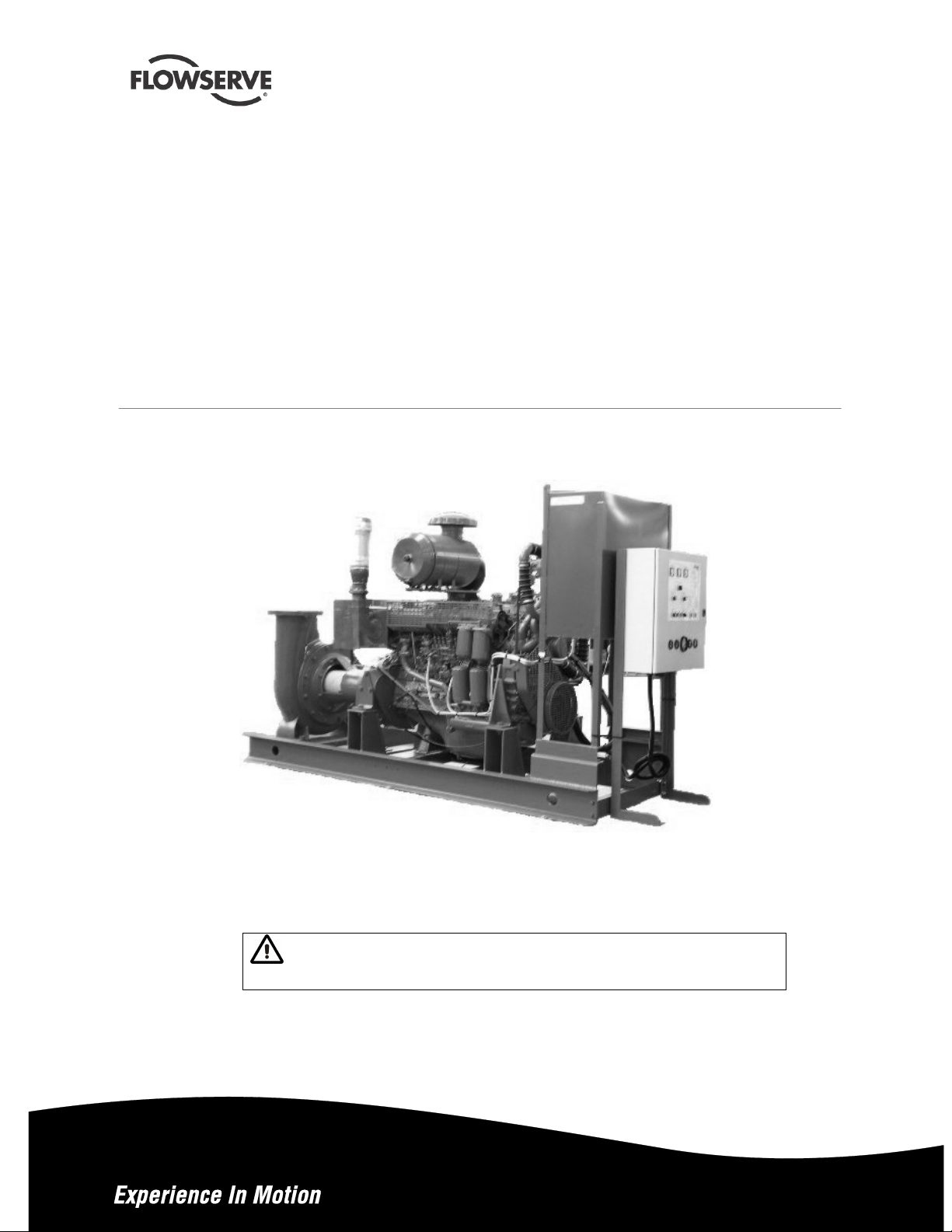
MEN / MHP, MEN-TI
(Sealed for life
bearings)
ME-TI (AND OTHER PUMPS)
Motor-pump unit reserved exclusively for
fire-fighting purposes. Diesel engine cooled with a spent
water heat exchanger centrifugal pump
PCN=71576298 - 11-09 (E) Original instructions.
USER INSTRUCTIONS
Installation
Operation
Maintenance
These instructions must be read prior to installing,
operating, using and maintaining this equipment.
Page 2

®
MEN USER INSTRUCTIONS ENGLISH 71576288 – 11-09
CONTENTS
PAGE
1 INTRODUCTION AND SAFETY ...........................4
1.1 G
ENERAL
1.2 CE
1.3 D
ISCLAIMER
1.4 C
OPYRIGHT
1.5 D
UTY CONDITIONS
1.6 S
AFETY
1.7 N
AMEPLATE AND SAFETY LABELS
1.8 S
PECIFIC MACHINE PERFORMANCE
1.9 N
OISE LEVEL
2 TRANSPORT AND STORAGE .............................7
2.1 C
ONSIGNMENT RECEIPT AND UNPACKING
2.2 H
ANDLING
2.3 L
IFTING
2.4 S
TORAGE
2.5 R
ECYCLING AND END OF PRODUCT LIFE
3 PUMP DESCRIPTION...........................................9
3.1 C
ONFIGURATIONS
3.2 N
OMENCLATURE
4 INSTALLATION....................................................11
4.1 L
OCATION
4.2 F
OUNDATION
4.3 G
ROUTING
4.4 I
NITIAL ALIGNMENT
4.5 P
IPING
4.6 E
LECTRICAL CONNECTIONS
4.7 C
ONNECTION
4.8 B
ATTERIES
4.9 S
WITCHING ON
4.10 C
4.11 F
4.12 P
4.13 O
5 COMMISSIONING, START-UP, OPERATION AND
SHUTDOWN...........................................................18
5.1 G
UARDING
5.2 P
RIMING AND AUXILIARY SUPPLIES
5.3 S
TARTING THE PUMP
5.4 R
UNNING THE PUMP
5.5 S
TOPPING AND SWITCHING OFF
.........................................................4
MARKING AND APPROVALS
......................................................4
......................................................4
............................................4
............................................................5
....................................................7
........................................................7
............................................................8
.........................................................8
.............................................9
.............................................10
.......................................................11
..................................................11
......................................................11
..........................................12
...........................................................13
..................................................16
.....................................................17
................................................17
HARGE STARTER BATTERIES
INAL SHAFT ALIGNMENT CHECK
ROTECTION SYSTEMS
THER CHECK
..............................................18
......................................................18
.......................................19
........................................24
...........................4
.......................6
....................6
.............................16
........................17
.....................17
..................................18
...................18
.......................25
............7
..............9
PAGE
6 MAINTENANCE...................................................25
6.1 G
ENERAL
6.2 M
AINTENANCE SCHEDULE
6.3 S
PARE PARTS
6.4 R
ECOMMENDED SPARES AND CONSUMABLE ITEMS
6.5 D
ISASSEMBLY
7 FAULTS; CAUSES AND REMEDIES ..................31
7.1 F
AULTS ON THE PUMP
7.2 E
LECTRICAL FAULTS
8 PARTS LIST AND DRAWINGS ...........................32
8.1 S
ECTIONAL DRAWINGS
8.2 S
ECTIONAL DRAWINGS PART LIST
8.3 G
ENERAL ARRANGEMENT DRAWING
9 CERTIFICATION .................................................35
10 OTHER RELEVANT DOCUMENTATION AND
MANUALS...............................................................35
10.1 S
10.2 C
10.3 A
........................................................25
................................26
..................................................29
.................................................29
.....................................31
........................................32
....................................32
.....................34
UPPLEMENTARY USER INSTRUCTIONS
HANGE NOTES
DDITIONAL SOURCES OF INFORMATION
............................................35
.................35
..........35
.........35
29
Page 2 of 36
Page 3

®
MEN USER INSTRUCTIONS ENGLISH 71576288 – 11-09
INDEX
PAGE
Additional sources (10.3).......................................35
Alignment of shafting (see 4.2, 4.4 and 4.11)
Batteries (4.8) ........................................................17
CE marking and approvals (1.2)..............................4
Certification (9) ......................................................35
Change notes (10.2)..............................................35
Charge starter batteries (4.10) ..............................17
Commissioning, start-up, operation (5) .................18
Configurations (3.1) .................................................9
Connection (4.7) ....................................................16
Copyright (1.4).........................................................4
Coupling assembly (4.4.1).....................................12
Disassembly (6.5)..................................................29
Disclaimer (1.3)........................................................4
Dismantling (see 6.5, Disassembly)......................29
Drawings (8.1) .......................................................32
Drive shaft assembly (4.4.2)..................................13
Duty conditions (1.5)................................................4
Electrical connections (4.6) ...................................16
End of product life (2.5) ...........................................9
Faults; causes and remedies (7) ...........................31
Final checks (4.5.3) ..............................................16
Foundation (4.2) ....................................................11
Forces and moments (see 4.5.1)...........................13
General arrangement drawing (8.3) ......................35
Gland packing (6.2.2) ............................................28
Grouting (4.3).........................................................11
Guarding (5.1)........................................................18
Handling (2.2) ..........................................................7
Installation (4) ........................................................11
Lifting (2.3)...............................................................8
Local signalization table (see 5.3.2.1)...................19
Location (4.1).........................................................11
Maintenance (5.3.2.3 and 6)
Maintenance schedule (6.2) ..................................26
Nomenclature (3.2)................................................10
Nameplate and safety labels (1.7)...........................6
Operating limits (see 3.1) ........................................9
Ordering spare parts (6.3.1) ..................................29
Parts lists (8.2).......................................................34
Piping (4.5) ............................................................13
Protection systems (4.12)......................................18
Pump masses (2.2.2) ..............................................8
Receipt and unpacking (2.1)....................................7
Recommended spares (6.4) ..................................29
Recycling (2.5).........................................................8
Replacement parts (see 6.3 and 6.4) ....................29
Running the pump (5.4).........................................24
Safety action (1.6.3).................................................5
Safety markings (1.6.1)............................................5
Safety, protection systems (see 1.6 and 4.12)
Sectional drawings (8.1) ........................................32
Sound level (see 1.9, Noise level)...........................7
Sources, additional information (10.3)...................35
Spare parts (6.3 and 6.4).......................................29
Specific machine performance (1.8)........................6
Standard maintenance (6.2.1) ..............................28
Starting the pump (5.3)..........................................19
Starting the diesel engine (5.3.2)...........................19
Stopping and switching off (5.5) ............................25
Storage, pump (2.4).................................................8
Storage, spare parts (6.3.2)...................................29
Supplementary manuals or information sources
(10.1)......................................................................35
Switching on (4.9) ..................................................17
Thermal expansion (4.4.1.1) .................................12
Transport and storage (2) .......................................7
Trouble-shooting (see 7)........................................31
PAGE
Page 3 of 36
Page 4
®
MEN USER INSTRUCTIONS ENGLISH 71576288 – 11-09
1 INTRODUCTION AND SAFETY
1.1 General
These instructions must always be kept
close to the product's operating location or
directly with the product.
Flowserve’s products are designed, developed and
manufactured with state-of-the-art technologies in
modern facilities. The unit is produced with great
care and commitment to continuous quality control,
utilizing sophisticated quality techniques, and safety
requirements.
Flowserve is committed to continuous quality
improvement and being at service for any further
information about the product in its installation and
operation or about its support products, repair and
diagnostic services.
These instructions are intended to facilitate
familiarization with the product and its permitted use.
Operating the product in compliance with these
instructions is important to help ensure reliability in
service and avoid risks. The instructions may not
take into account local regulations; ensure such
regulations are observed by all, including those
installing the product. Always coordinate repair
activity with operations personnel, and follow all
plant safety requirements and applicable safety and
health laws and regulations.
These instructions must be read prior to
installing, operating, using and maintaining the
equipment in any region worldwide. The
equipment must not be put into service until all
the conditions relating to safety noted in the
instructions, have been met. Failure to follow
and apply the present user instructions is
considered to be misuse. Personal injury,
product damage, delay or failure caused by
misuse are not covered by the Flowserve
warranty.
1.2 CE marking and approvals
It is a legal requirement that machinery and
equipment put into service within certain regions of
the world shall conform with the applicable CE
Marking Directives covering Machinery and, where
applicable, Low Voltage Equipment, Electromagnetic
Compatibility (EMC), Pressure Equipment Directive
(PED) and Equipment for Potentially Explosive
Atmospheres (ATEX).
Where applicable the Directives and any additional
Approvals cover important safety aspects relating to
machinery and equipment and the satisfactory
provision of technical documents and safety
instructions. Where applicable this document
incorporates information relevant to these Directives
and Approvals.
To confirm the Approvals applying and if the product is
CE marked, check the serial number plate markings
and the Certification. (See section 9, Certification.)
1.3 Disclaimer
Information in these User Instructions is believed
to be reliable. In spite of all the efforts of Flowserve
Pump Division to provide sound and all necessary
information the content of this manual may appear
insufficient and is not guaranteed by Flowserve as
to its completeness or accuracy.
Flowserve manufactures products to exacting
International Quality Management System Standards
as certified and audited by external Quality Assurance
organizations. Genuine parts and accessories have
been designed, tested and incorporated into the
products to help ensure their continued product quality
and performance in use. As Flowserve cannot test
parts and accessories sourced from other vendors the
incorrect incorporation of such parts and accessories
may adversely affect the performance and safety
features of the products. The failure to properly select,
install or use authorized Flowserve parts and
accessories is considered to be misuse. Damage or
failure caused by misuse is not covered by the
Flowserve warranty. In addition, any modification of
Flowserve products or removal of original components
may impair the safety of these products in their use.
1.4 Copyright
All rights reserved. No part of these instructions may
be reproduced, stored in a retrieval system or
transmitted in any form or by any means without
prior permission of Flowserve.
1.5 Duty conditions
This product has been selected to meet the
specifications of your purchaser order. The
acknowledgement of these conditions has been sent
separately to the Purchaser. A copy should be kept
with these instructions.
The product must not be operated beyond
the parameters specified for the application. If
there is any doubt as to the suitability of the
product for the application intended, contact
Flowserve for advice, quoting the serial number.
If the conditions of service on your purchase order
are going to be changed (for example liquid pumped
temperature or duty) it is requested that the user
seeks the written agreement of Flowserve before
start up.
Page 4 of 36
Page 5
®
MEN USER INSTRUCTIONS ENGLISH 71576288 – 11-09
1.6 Safety
1.6.1 Summary of safety markings
These User Instructions contain specific safety
markings where non-observance of an instruction
would cause hazards. The specific safety markings
are:
This symbol indicates electrical safety
instructions where non-compliance will involve a
high risk to personal safety or the loss of life.
This symbol indicates safety instructions where
non-compliance would affect personal safety and
could result in loss of life.
This symbol indicates “hazardous substances
and toxic fluid” safety instructions where noncompliance would affect personal safety and could
result in loss of life.
This symbol indicates safety
instructions where non-compliance will involve some
risk to safe operation and personal safety and would
damage the equipment or property.
This sign is not a safety symbol but indicates
an important instruction in the assembly process.
1.6.2 Personnel qualification and training
All personnel involved in the operation, installation,
inspection and maintenance of the unit must be
qualified to carry out the work involved. If the
personnel in question do not already possess the
necessary knowledge and skill, appropriate training
and instruction must be provided. If required the
operator may commission the manufacturer/supplier
to provide applicable training.
Always coordinate repair activity with operations and
health and safety personnel, and follow all plant
safety requirements and applicable safety and health
laws and regulations.
1.6.3 Safety action
This is a summary of conditions and actions to
prevent injury to personnel and damage to the
environment and to equipment. For products
used in potentially explosive atmospheres
section 1.6.4 also applies.
NEVER DO MAINTENANCE WORK
WHEN THE UNIT IS CONNECTED TO POWER
GUARDS MUST NOT BE REMOVED WHILE
THE PUMP IS OPERATIONAL
DRAIN THE PUMP AND ISOLATE
PIPEWORK BEFORE DISMANTLING THE PUMP
The appropriate safety precautions should be taken
where the pumped liquids are hazardous.
FLUORO-ELASTOMERS (When fitted.)
When a pump has experienced temperatures over
250 ºC (482 ºF), partial decomposition of fluoroelastomers (example: Viton) will occur. In this
condition these are extremely dangerous and skin
contact must be avoided.
HANDLING COMPONENTS
Many precision parts have sharp corners and the
wearing of appropriate safety gloves and equipment
is required when handling these components. To lift
heavy pieces above 25 kg (55 lb) use a crane
appropriate for the mass and in accordance with
current local regulations.
THERMAL SHOCK
Rapid changes in the temperature of the liquid within
the pump can cause thermal shock, which can result
in damage or breakage of components and should
be avoided.
NEVER APPLY HEAT TO REMOVE
IMPELLER
Trapped lubricant or vapor could cause an explosion.
HOT (and cold) PARTS
If hot or freezing components or auxiliary heating
supplies can present a danger to operators and
persons entering the immediate area action must be
taken to avoid accidental contact. If complete
protection is not possible, the machine access must
be limited to maintenance staff only, with clear visual
warnings and indicators to those entering the
immediate area. Note: bearing housings must not be
insulated and drive motors and bearings may be hot.
If the temperature is greater than 68 °C (155 °F)
or below -5 °C (23 °F) in a restricted zone, or
exceeds local regulations, action as above shall
be taken.
HAZARDOUS LIQUIDS
When the pump is handling hazardous liquids care
must be taken to avoid exposure to the liquid by
appropriate sitting of the pump, limiting personnel
access and by operator training. If the liquid is
flammable and/or explosive, strict safety procedures
must be applied.
Gland packing must not be used when pumping
hazardous liquids.
Page 5 of 36
Page 6
®
MEN USER INSTRUCTIONS ENGLISH 71576288 – 11-09
PREVENT EXCESSIVE EXTERNAL
PIPE LOAD
Do not use pump as a support for piping. Do not
mount expansion joints, unless allowed by
Flowserve in writing, so that their force, due to
internal pressure, acts on the pump flange.
ENSURE CORRECT LUBRICATION
(See section 5, Commissioning, startup, operation
and shutdown.)
START THE PUMP WITH OUTLET
VALVE PART OPENED
(Unless otherwise instructed at a specific point in the
User Instructions.)
This is recommended to minimize the risk of
overloading and damaging the pump motor at full or
zero flow. Pumps may be started with the valve
further open only on installations where this situation
cannot occur. Pump outlet valve shall may need to
be adjusted to comply with the duty following the
run-up process. (See section 5, Commissioning
start-up, operation and shutdown.)
1.7 Nameplate and safety labels
1.7.1 Nameplate
For details of nameplate, see the Declaration of
Conformity, or separate documentation included
with these User Instructions.
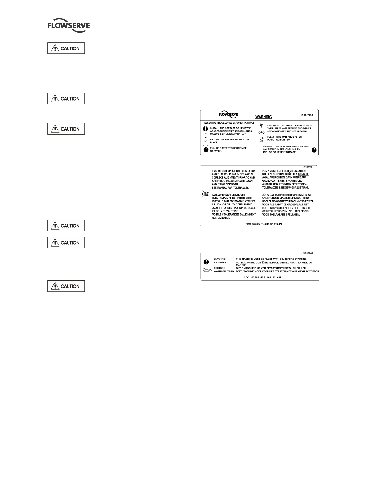
1.7.2 Safety labels
NEVER RUN THE PUMP DRY
INLET VALVES TO BE FULLY OPEN
WHEN PUMP IS RUNNING
Running the pump at zero flow or below the
recommended minimum flow continuously will cause
damage to the seal.
DO NOT RUN THE PUMP AT
ABNORMALLY HIGH OR LOW FLOW RATES
Operating at a flow rate higher than normal or at a
flow rate with no backpressure on the pump may
overload the motor and cause cavitations. Low flow
rates may cause a reduction in pump/bearing life,
overheating of the pump, instability and
cavitations/vibration.
1.6.4 Preventing the build up of explosive
mixtures
ENSURE PUMP IS PROPERLY FILLED AND
VENTED AND DOES NOT RUN DRY.
Ensure pump and relevant suction and discharge
pipeline system is totally filled with liquid at all times
during the pump operation, so that an explosive
atmosphere is prevented. In addition it is essential to
make sure that seal chambers, auxiliary shaft seal
systems and any heating and cooling systems are
properly filled.
If the operation of the system cannot avoid this
condition the fitting of an appropriate dry run
protection device is recommended (eg liquid
detection or power monitor).
Oil lubricated units only:
1.8 Specific machine performance
For performance parameters see section 1.5, Duty
conditions. When the contract requirement specifies
these to be incorporated into User Instructions these
are included here. Where performance data has
been supplied separately to the purchaser these
should be obtained and retained with these User
Instructions if required.
Page 6 of 36
Page 7

®
MEN USER INSTRUCTIONS ENGLISH 71576288 – 11-09
1.9 Noise level
Attention must be given to the exposure of
personnel to the noise, and local legislation will
define when guidance to personnel on noise
limitation is required, and when noise exposure
reduction is mandatory. This is typically 80 to 85
dBA.
The usual approach is to control the exposure time
to the noise or to enclose the machine to reduce
emitted sound. You may have already specified a
limiting noise level when the equipment was
ordered, however if no noise requirements were
defined, then attention is drawn to the following table
to give an indication of equipment noise level so that
you can take the appropriate action in your plant.
Pump noise level is dependent on a number of
operational factors, flow rate, pipework design and
acoustic characteristics of the building, and so the
values given are subject to a 3 dBA tolerance and
cannot be guaranteed.
Similarly the motor noise assumed in the “pump and
motor” noise is that typically expected from standard
and high efficiency motors when on load directly
driving the pump. Note that a motor driven by an
inverter may show an increased noise at some
speeds.
If a pump unit only has been purchased for fitting
with your own driver then the “pump only” noise
levels in the table should be combined with the level
for the driver obtained from the supplier. Consult
Flowserve or a noise specialist if assistance is
required in combining the values.
It is recommended that where exposure approaches
the prescribed limit, then site noise measurements
should be made.
The values are in sound pressure level LpA at 1 m
(3.3 ft) from the machine, for “free field conditions
over a reflecting plane”.
For estimating sound power level LWA (re 1 pW) then
add 17 dBA to the sound pressure value.
In areas where the staff has to intervene, remember
that when the level of the sound pressure is:
• Below 70 dBA: it is not necessary to take special
precautions.
• Above 70 dBA: people working continuously in
the machine room must be supplied with
protective devices against noise.
• Below 85 dBA: no particular measures need to
be taken for casual visitors staying in the room
during a limited period.
• Above 85 dBA: the room must be considered as
a dangerous area because of the noise and a
warning sign must be fixed at each entry
warning the people coming into the room, even
for a short period, that they must wear hearing
protection.
• Above 105 dBA: special hearing protection
adapted to this noise level and to the spectral
noise components must be installed and a
warning sign to this effect erected at each entry.
The staff in the room must wear ear protection.
Make sure that the noise, which travels through the
walls and windows, does not generate too high
noise levels in the machine room's surroundings.
In areas where the staff has to intervene, remember
that when the level of the sound pressure is:
2 TRANSPORT AND STORAGE
2.1 Consignment receipt and unpacking
Immediately after receipt of the equipment it must be
checked against the delivery and shipping
documents for its completeness and that there has
been no damage in transportation.
Note all reserves on the signed shipping note which
is given back to the hauler. Later, claims cannot be
accepted.
Check any crate, boxes and wrappings for any
accessories or spare parts that may be packed
separately with the equipment or attached to
sidewalls of the box or equipment.
Each product has a unique serial number. Check
that this number corresponds with that advised and
always quotes this number in correspondence as
well as when ordering spare parts or further
accessories.
2.2 Handling
2.2.1 General instructions concerning handling
Boxes, crates, pallets or cartons may be unloaded
using forklift vehicles or slings dependent on their
size and construction.
To lift heavy pieces above 25 kg (55 lb), use a winch
adapted to the mass and in accordance with the
current local regulations.
To lift machines or pieces with one or several
suspension rings, only use hooks and chains in
compliance with the local regulations concerning
safety. Never put cables, chains or ropes directly on
or in the suspension rings. Cables, chains or lifting
ropes must never present excessive bending.
Page 7 of 36
Page 8
®
MEN USER INSTRUCTIONS ENGLISH 71576288 – 11-09
Never bend the lifting hooks, suspension rings,
chains, etc., which should only be made to endure
stresses within, calculated limits. Remember that the
capacity of a lifting device decreases when the
direction of the lifting force direction makes an angle
with the device axis.
To increase the safety and the efficiency of the lifting
device, all the lifting elements must be as
perpendicular as possible. If necessary a lifting
beam can be placed between the winch and the
load.
When heavy pieces are lifted up, never stay or work
under the load or in the area, which could be in the
path of the load if it were to swing or fall away.
Never leave a load hanging from a winch. The
acceleration or the slowing-down of lifting equipment
must stay in the safety limits for the staff.
A winch must be positioned in such a way that the
load will be raised perpendicularly. Where possible
necessary precautions must be taken to avoid the
swing of the load, using for example two winches
making approximately the same angle, below 30°,
with the vertical.
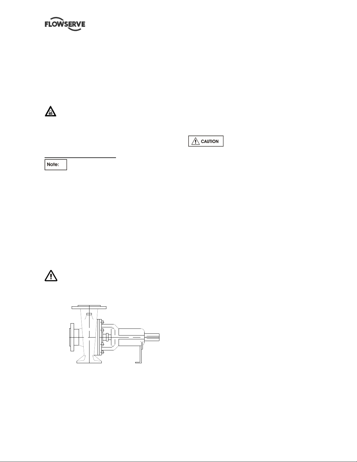
2.2.2 Pump masses
The masses of the pumps bare end of shaft are
shown on the nameplate.
All motors (for masses see the motor description
plate) must be handled with a winch.
Motor pump unit
Bareshaft pump
For masses above 25 kg (55 lb), manual
handling is forbidden.
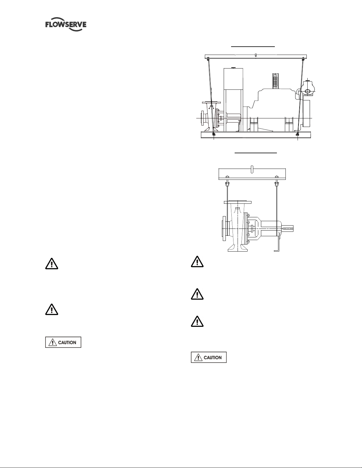
2.3 Lifting
2.3.1 Slinging of motor pumps units
Use handling means in accordance with motor
pump unit mass mentioned on the CE plate. For the
masses of the pumps bare end of shaft see table §
2.2.2 and nameplate.
To avoid distortion, the pump unit
should be lifted as shown.
Components weighing less than 25 kg (55 lb)
can be handled manually following the correct
actions and using the correct posture.
When handling always wear gloves, safety
boots and an industrial safety helmet.
For masses above 25 kg (55 lb), manual
handling is forbidden.
2.4 Storage
Store the pump in a clean, dry
location away from vibration. Leave piping
connection covers in place to keep dirt and other
foreign material out of pump casing. Turn pump at
intervals to prevent brinelling of the bearings and the
seal faces, if fitted, from sticking.
Do not store pumps starting on the fan guard.
The pump may be stored as above for up to 6
months. Consult Flowserve for preservative actions
when a longer storage period is needed.
Page 8 of 36
Page 9
®
MEN USER INSTRUCTIONS ENGLISH 71576288 – 11-09
2.5 Recycling and end of product life
At the end of the service life of the product or its
parts, the relevant materials and parts should be
recycled or disposed of using an environmentally
acceptable method and local regulations. If the
product contains substances which are harmful to
the environment, these should be removed and
disposed of in accordance with current regulations.
This also includes the liquids and or gases in the
"seal system" or other utilities.
Make sure that hazardous substances or toxic
fluid are disposed of safely and that the correct
personal protective equipment is used. The safety
specifications must be in accordance with the
current regulations at all times.
3 PUMP DESCRIPTION
Refer to the standard instructions if the
pump used is different to that indicated below. In all
cases the liquid temperature is limited to 25 °C.
3.1 Configurations
This centrifugal pump unit is designed for the
pumping of water [taken from a clean, nonaggressive, particle-free water supply].
The MEN pump or MEN-TI or ME-TI or MHP is a
single stage centrifugal pump with an axial inlet and
a vertical outlet. The dimensions of the volute pump
casing of the suction and discharge diameters as
well as the settlement feet correspond to standards:
DIN 24225 and NF EN 733 (excepted ME-TI and
MHP).
* Maximum working pressure at discharge:
- MEN, MEN-T: 16 bars
- ME-TI 200-400, ME-TI 250-400, ME-TI 200-500,
ME-TI 250-500 Cast iron GL :12 bars
- ME-TI 200-400 and ME-TI 250-400
Cast iron GS :12 bars
- ME-TI 200-500, ME-TI 250-500
Cast iron GS :15 bars
- MHP : 16 bars
* Maximum working pressure at suction : 10 bars
* Maximum pumped fluid temperature : 90 °C
* Maximum solid suspension : 50 g/m3
* Density : 1
* Viscosity : 1 mm²/s
The nominal speed is shown on the
pump nameplate.
The pump must be stored in a non-explosive,
ventilated location, sheltered from bad weather, dust
and vibrations.
The reliability of the delivered machine can only be
ensured if it is used and serviced according to the
conditions given in this manual. The maximum
values specified in this manual must never be
exceeded.
Page 9 of 36
Page 10
®
Type kg Refer.
Q
Manuf. N
H m
t
emp. °C
Satndard
Type
Engine
Type
Q
m3/h
H m
%
P
KW
MEN USER INSTRUCTIONS ENGLISH 71576288 – 11-09
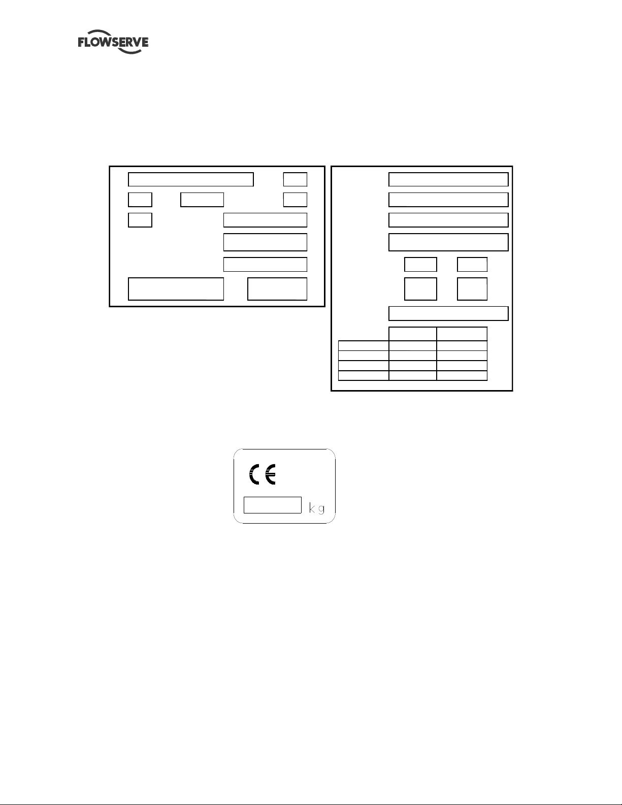
3.2 Nomenclature
Characteristics shown on the nameplate fixed on the pump are as shown below:
Each pump is supplied with the following nameplate:
Pump
m3/h
Max/min
Bearing
rad/thrust
Year +
Manuf. N
min-1 Max pr.
bar
Unit
Year +
Power Nom.
Power Max.
Pump Type
100%
KW for
KW for
min-1
min-1
130%
Each pump unit is supplied with the following nameplate:
Mass of the set:
Eff.
Page 10 of 36
Page 11
®
NF E 27 811
MEN USER INSTRUCTIONS ENGLISH 71576288 – 11-09
4 INSTALLATION
4.1 Location
The pump should be located to allow room for
access, ventilation, maintenance and inspection with
ample headroom for lifting and should be as close as
practicable to the supply of liquid to be pumped, and
to the venting system.
Disconnect the switching enclosure support from the
pump support by removing the fastening bolts. The
switching enclosure support must be off-set with
respect to the pump motor base.
4.2 Foundation
There are many methods of installing
pump units to their foundations. The correct method
depends on the size of the pump unit, its location
and noise vibration limitations. Non-compliance with
the provision of correct foundation and installation
may lead to failure of the pump and, as such, would
be outside the terms of the warranty. The base plate
should be mounted onto a firm foundation, either an
appropriate thickness of quality concrete or sturdy
steel framework. It should NOT be distorted or pulled
down onto the surface of the foundation, but should
be supported to maintain the original alignment.
Anchor bolts must be in accordance with the foot
bolt holes. Use anchor bolts of accepted standards
and sufficient to ensure safe fitting in the foundation.
Particularly, this applies to individual plates where
the anchor bolts have to withstand the driving
torque.
Provide sufficient space in the foundation to
accommodate the anchor bolts. If necessary,
provide concrete risers.
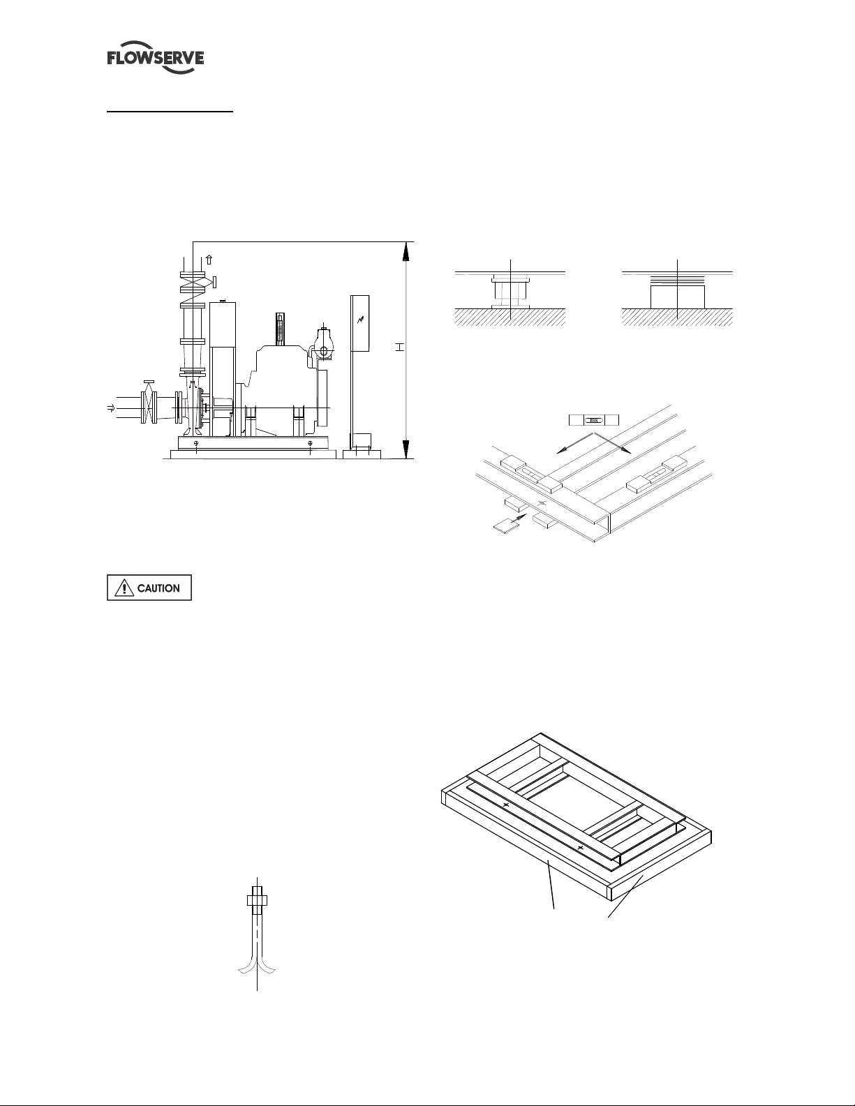
4.2.1 Setting the base plate for anchoring
- Clean the foundation surface thoroughly.
- Put shims on the foundation surface (approx 20-25
mm thick), one on each side of the bolt hole (as an
alternative, leveling screws can be used).
- Lay the base plate and level in both directions with
extra shims. The base plate should be level to within
0.5 mm per 1 m.
If anchor bolts have been pre-cast in the foundation
slightly tighten the anchor bolts. Otherwise let them
hang in the foundation holes.
4.3 Grouting
4.3.1 Base plate grouting
Prepare the site for grouting. Before grouting clean
the foundation surface thoroughly and provide
external barriers as shown:
barriers
Prepare grouting product (concrete, resin) in
accordance with manufacturers' instructions.
Page 11 of 36
Page 12

®
MEN USER INSTRUCTIONS ENGLISH 71576288 – 11-09
Use grouting products with anti-shrinking
components.
- To grout up to the required level. Polish surfaces.
Take necessary precautions to avoid air bubbles.
- Lay-down the barrier, break external angles, and
polish the different surfaces.
- After grout starts to cure, definitively tighten
anchor bolts.
- Control the alignment such as described as
follows:
4.4 Initial alignment
4.4.1 Coupling assembly
4.4.1.1 Thermal expansion
The pump and motor will normally
have to be aligned at ambient temperature and
should be corrected to allow for thermal expansion
at operating temperature. In pump installations
involving high liquid temperatures, the unit should be
run at the actual operating temperature, shut down
and the alignment checked immediately.
4.4.1.2 Alignment methods
Ensure pump and driver are isolated
electrically; that the batteries and start-up shunt are
disconnected and the half couplings are
disconnected. Ensure that the pump piping, suction
and discharge, is disconnected.
The alignment MUST be checked.
Although the pump will have been aligned at the
factory it is most likely that this alignment will have
been disturbed during transportation or handling. If
necessary, align the motor to the pump, not the
pump to the motor.
Alignment
Parallelism and concentricity check
Operations to be carried out by
qualified FLOWSERVE employees only.
Check the alignment at three or four
points, before piping assembly.
with a rule with a comparator
Admissible margin for a motor with roller bearings:
= 0.15 mm parallel checking
= 0.1 mm angular checking
Angular checking:
with a sliding rule with a caliper gauge
The alignment will be definitive only
after piping connection (see § 4.5.1).
After alignment, the coupling protection cover
must be refitted.
If necessary, improve the machine alignment:
→
Complete unit mounted on common base plate:
The machines are first aligned accurately in our
workshops. Usually, any misalignment observed onsite is due to a wrong adjustment under the base
plate (disturbed during transport or because of
forces exerted by the piping). It is only necessary to
rectify the adjustment under base plate. If it proves
to be insufficient, modify the motor and/or the piping
and pump adjustment.
Page 12 of 36
Page 13

®
Reference A/B
Reference C/D
Reference A/B
Reference C/D
MEN USER INSTRUCTIONS ENGLISH 71576288 – 11-09
4.4.2 Drive shaft assembly
The battery must be disconnected. The distance
between the end of the pump shaft and the engine
flywheel must be 380 mm ± 5 mm. The pump and
diesel engine must be aligned once the cardan link
is fitted between the pump shaft and the engine
flywheel.
The maximum axial misalignment allowed between
the pump and the engine flywheel shaft is 9 mm ±
4.5 mm on each side of the shaft used as a
reference for alignment (see fig.1).
All that is required to align the pump and engine
drive shafts correctly is a measuring tape or ruler
graded in millimeters.
Alignment is checked as indicated below:
1) See fig.2
Place the marking A/B engraved on the surface of
the cardan link flange at the top in the vertical
position (12 o’clock).
Measure the distance X between the flange and the
outside of the cardan shaft (point A). This distance
must be 76 mm ± 3 mm.
With the cardan in the same position as above,
measure the distance Y between the flange and the
outside of the cardan shaft (point B). This distance
must be equal to the distance X ± 1mm.
2) See fig.3
Turn the cardan 90° and place markings C/D
engraved on the surface of the cardan link flange at
the top in the vertical position.
Measure the distance X1 between the plate and
outside of the cardan shaft (point A). This distance
must be 78 mm ± 1 mm.
With the cardan in the same position as above,
measure the distance Y1 between the flange and
outside of the cardan shaft (point B). This distance
must be equal to the distance X1 ± 1mm.
Alignment is achieved by moving and/or shimming
one or both of the elements.
Pump side
Pump side
Pump side
Pump side
The maximum misalignment
allowed between the pump and
engine axis is 9 mm ± 4.5 mm
Motor side
Motor side
on drive shaft
on drive shaft
flange
flange
Motor side
Motor side
on drive shaft
on drive shaft
flange
flange
Motor side Pump side
Motor side Pump side
4.5 Piping
Protective covers are fitted to the
pipe connections to prevent foreign bodies entering
during transportation and installation. Ensure that
these covers are removed from the pump before
connecting any pipes.
4.5.1 Suction and discharge piping
The dimensions of the pipes do not directly depend
on suction and discharge diameters of the pump:
a) First, choose a flow speed < 2 m/s at suction, and
about 3 m/s at discharge.
b) Take into account the available NPSH, which
must be superior to the required NPSH of the pump.
Never use pump as a support for piping. Do not
mount expansion joints in such a way that their
force, due to internal pressure, may act on the pump
flange.
Maximum forces and moments allowed on the pump
flanges vary with the pump size and type. These
external strains may cause misalignment, hot
bearings, worn couplings, vibrations and the
possible failure of the pump casing.
Page 13 of 36
Page 14

®
MEN USER INSTRUCTIONS ENGLISH 71576288 – 11-09
When designing the pipes (§ 4.5.2.1, § 4.5.2.2) take
necessary precautions in order not to exceed
maximum allowed strains.
Forces and moments applied to the pump flanges
must never exceed the values shown in the table
below.
If the pump used is different to that
indicated below, refer to the standard instructions
corresponding to this pump.
ME-TI
PUMP
150 160 200 180 310 45 60 80 110
200 215 265 240 415 85 100 125 180
Vertical 250 270 335 300 520 125 145 180 260
300 320 400 360 625 170 200 240 355
Discharge 350 375 465 420 730 220 255 310 455
400 430 530 480 835 275 320 390 570
450 485 600 540 940 340 390 480 705
500 540 665 600 1040 410 470 580 850
150 180 160 200 315 45 60 80 110
200 240 215 265 415 85 100 125 180
Horizontal 250 300 270 335 520 125 145 180 260
300 360 320 400 625 170 200 240 355
Suction 350 420 375 465 730 220 255 310 455
400 480 430 530 835 275 320 390 570
450 540 485 600 940 340 390 480 705
500 600 540 665 1040 410 470 580 850
PUMP
50-32-125 50 32 125 95 20
50-32-160 50 32 125 95 17
50-32-200 50 32 125 95 17
50-32-200L 50 32 125 95 17
65-40-125 65 40 135 100
65-40-160 65 40 135 100
65-40-200L 65 40 135 100
65-40-250 65 40 135 100
65-40-250L 65 40 135 100
65-50-125 65 50 135 100
65-50-160 65 50 135 100
65-50-200L 65 50 135 100
65-50-250L 65 50 135 100
80-65-125 80 65 145 105
80-65-160 80 65 145 105
80-65-200L 80 65 145 105
80-65-250L 80 65 145 105
80-65-315 80 65 145 105
100-80-160 100 80 180 125
100-80-200L 100 80 180 125
100-80-250L 100 80 180 125
100-80-315 100 80 180 125
125-100-200L 125 100 320 190
125-100-250L 125 100 330 200 102
125-100-315 125 100 310 185
125-100-315L 125 100 310 185
125-100-400 125 100 285 170
125-100-400L 125 100 285 170
150-125-250L 150 125 450 290 155
150-125-315L 150 125 415 260 140
150-125-400L 150 125 410 255 137
200-150-315L 200 150 500 325 175
200-150-400L 200 150 500 325 175
DN Force (daN) Moments (m.daN)
Flange Fy Fz Fx
DNA
Discharg
e
DNR
(mm)
Suction
(mm)
∑F
Force
(daN)
Fv
max
My Mz Mx
Moments
(mdaN) MEN –TI
Fh
Σ Mt max
max
22
22
20
25
25
22
22
20
25
27
27
27
27
27
47
47
47
47
95
92
92
82
82
∑M
Page 14 of 36
Page 15

®
Battery
Sufficient
immersion : I
I ≥ 3 x D
with glycerin bath
MEN USER INSTRUCTIONS ENGLISH 71576288 – 11-09
4.5.2.2 Design of a suction lift line
The inlet pipe must be as short and as direct as
possible, never place an elbow directly on the pump
inlet nozzle.
Forces and moments values are applied to the
whole flanges and not flange-by-flange. For their
sharing out on the pump flanges, refer to standard
NFCR 13 391.
Ensure piping and fittings are flushed
before use.
Ensure piping for hazardous liquids is
arranged to allow pump flushing before removal of
the pump.
4.5.2 Suction piping
4.5.2.1 Design of a flooded suction line
The suction line must be as short and direct as
possible, never mount an elbow directly on the inlet
flange of the pump.
Non return
valve
Valve
Switching
enclosure Tank
Non return
valve
Valve
Tank
Sump suction configuration
a) Avoid sharp elbows or sudden narrowing. Use
convergent ≤ 20° (total angle) with upright
generating.
b) Arrange that the suction piping is inclined
upwards towards the pump ensuring that there are
no peaks.
c) In case of frost risks, the piping in question has to
be marked out.
d) If a foot valve is necessary, do not oversize it
because it would generate pulsations (valve
beating).
Switching
enclosure
Diesel engine
Battery
Diesel engine
Flooded suction configuration
a) Avoid sharp elbows or sudden narrowing. Use
convergent ≤ 20° (total angle).
b) Arrange the piping so that there are no air
pockets (no bulges).
c) If high points cannot be avoided in suction line,
provide them with air relief cocks.
d) In case of frost risks, the piping in question has to
be marked out.
e) If a strainer is necessary, its net area should be
three or four times the area of the suction pipe.
f) If an inlet valve is necessary, choose a model with
direct crossing.
Do not tighten flanges before the final
check (see § 4.5.3).
Do not tighten flanges before the final
check (see § 4.5.3).
If necessary, a control manometer can be connected
on the piping.
Control manometer
(discharge) with
glycerin bath
Control manometer (suction)
Installation of control manometers Class I
Do not tighten flanges before the final
check (see § 4.5.3).
Page 15 of 36
Page 16

®
3 5 3 6
MEN USER INSTRUCTIONS ENGLISH 71576288 – 11-09
4.5.3 Final checks
a) Check the tightening of anchor bolts. Tighten
them if necessary.
b) Check that protective covers on suction and
discharge flanges are removed.
c) Check that holes of piping flanges are parallel and
correspond to those of the pump.
d) Tighten suction and discharge flanges.
e) Check the alignment pump-motor according to the
procedure § 4.4.2.
Rectify if necessary by adjusting the motor only!
f) If it is planned, connect piping (hydraulic,
pneumatic, sealing system).
g) Control seal and the working of auxiliary piping.
4.6 Electrical connections
Electrical connections must be made
by a qualified Electrician in accordance with relevant
local national and international regulations. This
includes any grounding.
It is important to be aware of the EUROPEAN
DIRECTIVE on electromagnetic compatibility when
wiring up and installing equipment on site. Attention
must be paid to ensure that the techniques used during
wiring/installation do not increase electromagnetic
emissions or decrease the electromagnetic immunity of
the equipment, wiring or any connected devices. If in
doubt, contact Flowserve for advice.
The installation comprises all appropriate safety
devices such as magnetic overload, current
overload, earth leakage relays, etc.... Ensure the
power supply corresponds to the power rating given
for the switching enclosure, i.e.: 5 kVA (220 V).
An electrical protection device shall be fitted.
Carry out the ground connections according to the
current local regulations.
4.7 Connection
Proceed with electrical connections to the terminals
in accordance with instructions 71576402 01-06.
Connect the switching enclosure to the mains power
supply and check the supply voltage on terminals 39
and 40 (220 V single-phase).
Connect the start-up signal wires:
Double terminal n° 11: pressure switch N° 1. B-
contacts of these pressure switches must be
potential free.
Double terminal n° 12: pressure switch N° 2.
Actual recommendations require the startup signal contact to be open-started. All delivered
units meet this requirement.
Information regarding the cabinet:
Sensor connection at recovery tank level on #15
double terminal. The contact will be opened in case
of lack of water in the main tank and potential free.
Opening the circuit controlling the
primer tank starts the engine.
Options:
Sensor connection at the bottom of the primer tank
on #16 double terminal. The contact will be opened
in case of lack of water at the bottom of the primer
tank and is potential free.
Sluice blade or ventilation damper connection on
#43 and 44 double terminal (220 V servomotor).
Sluice blade opening limit connection on #15 double
terminal. The contact will be closed when ventilation
sluice blades are open and potential free.
Alarm report:
All alarm reports are proposed on 2 changeover
contacts (A and B) by 2 triple terminals.
Connection of running data motor on terminals
n° 35 and n° 36
1 0 4 1 0 7
1 0 5 1 0 8
1 0 6 1 0 9
A B
Manual connection of switching fault data on
terminals n° 33 and n° 34
A B
9 8 1 0 1
9 9 1 0 2
1 0 0 1 0 3
3 3 3 4
Page 16 of 36
Page 17

®
3 0 3 1
28
29
MEN USER INSTRUCTIONS ENGLISH 71576288 – 11-09
Connection of general fault data on terminals n° 30
and n° 31
8 9 9 2
9 0 9 3
9 1 9 4
A B
Information connection Failure risk on n° 28 and n°
29 terminals
83 8 6
8 4 87
85 8 8
A B
Information connection
No start-up on n° 37 and n° 38 terminals
1 1 1
A B
1 1 0
1 1 2
3 7 3 8
1 1 4
1 1 3
1 1 5
4.8 Batteries
The lead-cell batteries are supplied "dry charged".
Switch off the "AUTO-STOP-MANUAL" key switches
on the front panel of the switching enclosure.
Electrolyte is supplied by FLOWSERVE separately
in 1.7-litre plastic containers.
Electrolyte is a sulphuric acid-based liquid.
Appropriate protective clothing must be worn during
handling. Avoid any contact with skin or clothing. In
case of splashing, rinse thoroughly with running
water (in case of contact with eyes, consult a doctor
immediately).
Prepare the batteries 1 week before commissioning.
Fill the batteries with electrolyte up to the maximum
fill level indicated with a line in the top section of the
battery.
The cables must not be exposed to oil, diesel or acid
splashing and should be run accordingly.
Check that the batteries are connected to the right
poles and securely fastened (++ and --).
4.9 Switching on
The pump unit is supplied with the starter solenoid
disconnected to avoid accidental start-up of the
diesel engine during commissioning preparation
work.
Reconnection may only be carried out by an
employee qualified by FLOWSERVE, after
examination before start-up.
The unit may only be switched on by an employee
qualified by FLOWSERVE.
- Place the operating mode selector switch in the
"Off" position.
- Close the switching terminals 5 and 6.
- Close fuse holders F1 to F4 and the circuit-breaker
DD1.
A siren sounds when these electrical
circuits are closed, press the "Siren off" and "cancel
fault" push-buttons.
- Close the main circuit-breaker.
- The following indicators white/power on,
green/electronics on, green/ charge batteries 1 or 2
and orange/non-auto, must be on.
4.10 Charge starter batteries
Both batteries are connected independently and
alternatively to a self-regulated battery charger.
A possible charge fault is signaled by the "Charger 1
or charger 2 fault" indicator on the front panel of the
enclosure, with activation of a local audible alarm
signal and tripping of the general fault contact.
Each charger supplies the corresponding battery
with a variable charge current in accordance with the
battery charge level.
- Keep a bottle of distilled water available for topping
up of electrolyte level.
The battery voltage selector switch enables
monitoring of the battery voltage with charger supply
interrupted.
4.11 Final shaft alignment check
Check the alignment pump-motor according to the
procedure § 4.4.2.
Rectify if necessary by adjusting the motor only!
- If it is planned, connect piping (hydraulic,
pneumatic, sealing system)
- Control seal and the working of auxiliary piping.
Page 17 of 36
Page 18

®
MEN USER INSTRUCTIONS ENGLISH 71576288 – 11-09
4.12 Protection systems
If leakage of product from the pump or its associated
sealing system can cause a hazard it is
recommended that an appropriate leakage detection
system is installed.
To prevent excessive surface temperatures at
bearings it is recommended that temperature or
vibration monitoring are carried out.
4.13 Other check
See § 6.2
5 COMMISSIONING, START-UP,
OPERATION AND SHUTDOWN
These operations must be carried out by
fully qualified personnel. The operator must
monitor the machine as long as it is in operation.
5.1 Guarding
Guarding is supplied fitted to the pump set.
If this has been removed or disturbed ensure that all
the protective guards around the pump coupling and
exposed parts of the shaft are securely fixed.
5.2 Priming and auxiliary supplies
Ensure all electrical, hydraulic,
pneumatic, sealant and lubrication systems (as
applicable) are connected and operational.
Check that the supply pressures are
compatible with the equipment to be supplied.
The discharge pipe is headed and there is a by-pass
valve on the check valve, open slightly the discharge
valve.
When the pump is totally free of air bubbles, replace
the plugs.
Air escape
Fit a 1-inch pipe to enable
cooling of the combustion
engine
Priming of a flooded pump
5.2.2 Priming of a sump suction pump
Installation of a foot valve is imperative.
Fill the pump and suction pipe with liquid via the
priming tank.
Let air escape by removing the plugs located on the
piping.
When the pump is totally free of air bubbles, replace
the plugs.
Ensure the inlet pipe and pump
casing are completely full of liquid before starting
Priming tank
continuous duty operation.
5.2.1 Priming of a flooded pump
Air escape
Close the discharge valve, fill the pump by opening
the suction valve. Let air escape by removing the
plug located on the piping.
Fit a 1-inch pipe to enable
cooling of the combustion
engine
Priming of a sump suction pump
Page 18 of 36
Page 19

®
MEN USER INSTRUCTIONS ENGLISH 71576288 – 11-09
5.3 Starting the pump
5.3.1 Bring controls and preparation before the
first starting and after each service call
Necessarily:
Check the tightening of the different plugs.
Check that the gland lightly tightens the packing
rings.
Risk of seal ring overheating.
If a mechanical seal is fitted, refer to the
standard pump instructions.
5.3.2 Start the pump and diesel engine
This initial start-up of pump and diesel
engine may only be carried out by a qualified
FLOWSERVE employee.
A noise protection helmet must be worn by all
persons present in the vicinity.
Suction valves must be fully open
when pump is running. Never run the pump dry, it
will cause damage.
*Close the valve at discharge
* Start up the diesel engine and check the discharge
pressure.
If pressure is satisfactory, slowly OPEN the outlet
valve.
Do not run the pump with the outlet valve closed
during initial start-up and after each maintenance
intervention.
If NO pressure, or LOW pressure, STOP the pump.
Refer to fault finding chart for fault diagnosis.
5.3.2.1 Starting the diesel engine
→ Initial start-up:
* Start the plant at moderate speed with push
buttons to emergency start-up position 1 or 2.
* Check that the oil pressure indicated on the
switching enclosure pressure gauge complies with
the values given in the engine manual. If the oil
pressure indicated on the pressure gauge is low with
respect to these instructions, place the switch in the
“Off” position and stop the engine using the direct
stop control indicated "STOP" located on the
injection pump until the engine is entirely at
standstill.
→ Check engine cooling system:
* Check that the water in the primary cooling circuit
is flowing freely (evacuation of lost water, discharge
from heat exchanger), it must be possible to see and
feel this flow.
* Water flow must be visibly unrestricted on the
pump discharge side, with no shut-off elements
incorporated. This discharge generally occurs at
35/45 °C.
* Cooling water flow-rate is limited by an adjustable
throttle to obtain a flow-rate of approximately 30
liters/hour per kW.
* New circuits often contain impurities which may
quickly clog the protection filter. If the raw water flow
decreases, simply remove the filter and clean it until
the circuit is clean. This operation is to be repeated.
* The manual by-pass on the cooling circuit main
pipe is only used to ensure cooling, if necessary,
when the plant cannot be shut-down during an
intervention on the raw water filter or the hydraulic
valve.
ENSURE THE RAW WATER FILTER ON THE
MAIN COOLING CIRCUIT IS WEEKLY CLEANED.
→ Checks and adjustments:
* Progressively increase the engine speed until the
setting limiter is attained. This limiter is set to obtain
an off-load speed of 50 to 100 rpm above nominal
speed in order to compensate for approximately 5 %
motor slip between off-load and full-load engine
speeds.
* With the plant running normally, progressively
open the pump discharge valve until the specified
performance is attained.
* Check the water temperature with the thermostat
on the switching enclosure; this is only attained
progressively, especially at low pump flow-rate.
If the temperature is above 95 °C, turn the selector
switch to “Off” and activate the switch-off control
marked STOP.
In the beginning, when on load, the new
plant sometimes emits exhaust smoke after
start-up. This is perfectly normal and quickly
disappears. Allow sufficient air circulation
during initial start-up (work with doors open),
and/or wear a protection mask.
The switching enclosure is designed to detect and
signal certain anomalies.
→ When running:
* Oil pressure too low
* Overheating
Page 19 of 36
Page 20

®
MEN USER INSTRUCTIONS ENGLISH 71576288 – 11-09
If one of these faults occurs, the alarm is triggered
and signaled by:
- activation of the siren;
- illumination of the corresponding indicator;
- repeated signal on the terminal for transmission.
However, a fault does not stop the plant.
Immediate intervention is required to remedy the
fault.
- The siren may be switched off by pressing the
push-button "STOP SIREN". This operation does not
cancel the siren if the fault signal is present at the
alarm terminal.
- Turning the rotary key switch "CANCEL FAULT"
remains ineffective as long as the fault persists and
resets the audible alarm signal.
→ Simulation of faults:
The safety devices may be checked by simulating
faults:
a) Excess water temperature fault simulation by
circuit opening between 55 wires and grounds.
b) Oil pressure low by circuit opening between 35
and 56 wires. [No oil pressure by circuit opening
between wires 035 and 56] if the engine is at
standstill and by circuit closing (035 and 56) when
the engine is running.
Water temperature fault function is activated only
after an initial time period of approximately 10
seconds.
Oil pressure fault function is efficient only after an
initial time period of approximately 1 minute.
→ Check room ventilation:
Ensure that room ventilation is correct by
incorporating top and bottom air vents as standard
practice. These vents must each have a minimum
size of 0.5 m².
Engine overheating is generally due to:
- defective engine and/or room cooling,
- an exhaust pipe of insufficient diameter,
- non-standard utilization of the plant, in excess of its
design characteristics.
- insufficient room ventilation
The temperature read on the thermometer located
on the front panel of the switching enclosure must
be stable between 70 and 90 °C when the plant is
on-load and conform to nominal characteristics
indicated in the specifications.
If the cooling water temperature rises above this
threshold value, an audible alarm is triggered and a
light indicator switches on.
Do not run the pump at zero flow-rate for more
than 10 minutes as this will heat up the cooling
water intended to cool the engine.
After approximately one hour of operation, the plant
may be switched off by pressing the control button
marked STOP.
ACTION MAINTAINED UNTIL TOTAL
STANDSTILL OF THE ENGINE.
→ Automatic start-up pressure switch n °1 :
With the selector pressure switch n° 1 in the "AUTO"
position and selector pressure switch n° 2 on stop,
the contact given by one of the control pressure
switches provokes immediate start-up of the plant at
the set nominal speed.
* Supervision of start-up sequence
The engine should normally start up first time.
However, to overcome an anomaly such as:
- Low batteries, pump packing gland too tight
- No fuel
- Slight presence of air in the fuel circuit
- Engine and room insufficiently heated during cold
weather
The automatic system is designed to energize the
starter motor with 8-second impulses from each set
of batteries alternatively.
The standard setting is 4 impulses of 8 seconds with
a rest period of 3 seconds between each impulse.
At the end of a complete cycle, if the engine has not
started, the alarm "FAIL START" is triggered,
followed by:
- Activation of the siren
- Illumination of the "Fail start" indicator
- Repeated signal at the terminals for transmission.
The operator informed may attempt a manual start
by pressing the "EMERGENCY START" pushbutton.
→ Automatic start-up pressure switch n °2:
Same automatic start-up procedure with pressure
switch n °1 but in the reversed order.
* Simulation of a start-up sequence
It can be done by any of both selector pressure
switch n °1 and n° 2.
The first pressure switch contact to be opened will
initiate its start-up sequence.
To check the start-up sequence, a simulation may
be carried out in which the injection is blocked by
pressing and holding the stop control while the plant
is in "AUTO" mode and the contact of a pressure
switch is closed (pressure drop in the network).
Page 20 of 36
Page 21

®
MEN USER INSTRUCTIONS ENGLISH 71576288 – 11-09
NOTE: The "FAIL START" alarm is cancelled by:
- Pressing the "STOP SIREN" push-button
- Pressing the "CANCEL FAULT" turn-key switch
This operation also resets the automatic cycle.
All pressure switches have a differential
pressure. The contact triggered by a drop in
pressure is only re-established when this pressure
returns to a value greater than the pressure switch
set value.
→ Battery fault:
At standstill:
The plant comprises a starter battery voltagemonitoring device. If the battery voltage is not in the
required range, the battery fault is triggered,
followed by:
- illumination of the corresponding indicator for
battery 1 or battery 2,
- repeated signal on the terminals for transmission.
However, the plant continues to operate on the other
battery.
→ Technical room temperature control (optional):
A technical room temperature inferior to + 10 °C
lights up the "TEMPERATURE LOCAL
SPRINKLER" red LED and activates the siren and
the "FAILURE RISK" relay.
The siren can be stopped by pressing the "STOP
SIREN" pushbutton. But this does not clear the fault
which is reported on the alarm base station.
The "CLEAR DEFAULT" turn-key button is not
working as long as the fault is present. If it is
activated, it re-initiates the audible alarm.
→ Ventilation sluice blade control:
The ventilation sluice blade correct opening control
is in service after motor start-up and activates the
"VENTILATION SLUICE BLADE" red LED. The siren
and the "FAILURE RISK" relay are activated if the
sluice blade opening is not correct only after an
initial time period of approximately 10 seconds.
The siren can be stopped by pressing the "STOP
SIREN" pushbutton. But this does not clear the fault
which is reported on the alarm base station.
The "CLEAR DEFAULT" turn-key button is not
working as long as the fault is present. If it is
activated, it re-initiates the audible alarm.
→ Starter cabinet electric connection control:
A cut-off in the wiring between the cabinet and the
starter solenoid lights up the "CABINET STARTER
CONNECTION" red LED and activates the siren and
the "FAILURE RISK" relay.
The siren can be stopped by pressing the "STOP
SIREN" pushbutton. But this does not clear the fault
which is reported on the alarm base station.
The "CLEAR DEFAULT" turn-key button is not
working as long as the fault is present. If it is
activated, it re-initiates the audible alarm.
This fault is present only 1min30sec after start-up
attempt.
→ Recovery tank level control:
In case of insufficient water level in the recovery
tank, the "RECOVERY TANK LEVEL" LED lights up
and the siren and the "FAILURE RISK" relay are
activated.
The siren can be stopped by pressing the "STOP
SIREN" pushbutton. But this does not clear the fault
which is reported on the alarm base station.
The "CLEAR DEFAULT" turn-key button is not
working as long as the fault is present. If it is
activated, it re-initiates the audible alarm.
→ Filter clogging control (optional):
In case of raw water filter clogging or in case of
engine temperature increase (independently from
the water temperature alarm), the "FILTER
CLOGGING" red LED lights up and the siren and the
"FAILURE RISK" relay are activated.
The siren can be stopped by pressing the "STOP
SIREN" pushbutton. But this does not clear the fault
which is reported on the alarm base station.
The "CLEAR DEFAULT" turn-key button is not
working as long as the fault is present. If it is
activated, it re-initiates the audible alarm.
→ Diesel level control:
In case of low diesel level in fuel tank, the "DIESEL
LOW" LED lights up and the siren and the "FAILURE
RISK" relay are activated.
The siren can be stopped by pressing the "STOP
SIREN" pushbutton. But this does not clear the fault
which is reported on the alarm base station.
The "CLEAR DEFAULT" turn-key button is not
working as long as the fault is present. If it is
activated, it re-initiates the audible alarm.
→ Engine water reheating control:
When the engine water reheating protection circuitbreaker or reheating button are switched off, a red
"ENGINE REHEATING" light indicator, audible alarm
and "GENERAL FAULT relay are triggered
The siren can be stopped by pressing the "STOP
SIREN" pushbutton. But this does not clear the fault
which is reported on the alarm base station.
Page 21 of 36
Page 22

®
MEN USER INSTRUCTIONS ENGLISH 71576288 – 11-09
The "CLEAR DEFAULT" turn-key button is not
working as long as the fault is present. If it is
activated, it re-initiates the audible alarm.
When the engine is operating, the engine water
reheating is inhibited.
Mains cut-off lights up the reheating fault LED.
→ Engine water level control:
In case of low cooling water level in the engine, the
"ENGINE WATER LEVEL" red LED lights up and the
siren and the "FAILURE RISK" relay and plant
start-up are activated.
The siren can be stopped by pressing the "STOP
SIREN" pushbutton. But this does not clear the fault
which is reported on the alarm base station.
The "CLEAR DEFAULT" turn-key button is not
working as long as the fault is present. If it is
activated, it re-initiates the audible alarm.
→ Priming tank level control (optional):
In case of low water level in priming tank, the
"PRIMING TANK LEVEL" red LED lights up and the
siren and the "FAILURE RISK" relay are activated.
The unit then starts.
The siren can be stopped by pressing the "STOP
SIREN" pushbutton. But this does not clear the fault
which is reported on the alarm base station.
Check that the priming tank level is correct and stop
the unit using the STOP handle on the engine.
The "CLEAR DEFAULT" turn-key button is not
working as long as the fault is present. If it is
activated, it re-initiates the audible alarm and
restarts the motor pump if the level is not correct.
→ Control of pressure switch line:
In the case of a short circuit on the pressure switch
connection cables, the warning light "Pressure
Switch Line" lights up, and the alarm and "Risk of
failure" relay are activated.
The siren can be stopped by pressing the "STOP
SIREN" pushbutton. But this does not clear the fault
which is reported on the alarm base station.
The "CLEAR DEFAULT" turn-key button is not
working as long as the fault is present. If it is
activated, it re-initiates the audible alarm.
Page 22 of 36
Page 23

®
MEN USER INSTRUCTIONS ENGLISH 71576288 – 11-09
→ Local signalization table:
Green Live electronics Live electronic circuits (at least one of both power sources is
x Yellow x Mains shortage Pre-heating and charger electric circuits are not powered by
Green Battery 1 loading or Battery 2 loading Shows that corresponding battery is loading (1 LED per battery)
x Yellow x Charger 1 fault or Charger 2 fault Shows that corresponding battery charger does not deliver the
x Yellow x Battery 1 fault or Battery 2 fault Shows that corresponding battery cannot assume its function (1
x Red x Cabinet-starter connection Cabinet-starter connection non guaranteed
x Green Motor in operation Shows that the pump is operating
Green Pressure switch 1 start-up Shows that the pump has been started by pressure switch 1 or
Yellow Pressure switch 2 start-up Shows that the pump has been started by pressure switch 2 or
Green Auto position Pressure switch 1 or 2 controller is in automatic mode [element
x Red Non auto position Pressure switch 1 or 2 controller is on STOP or MANUAL
x Red x Not started Shows that the pump did not start automatically at the end of the
x Red x Water temperature Shows that cooling water temperature exceeds its limit (engine
x Red x Filter clogging (optional) Shows a filter clogging [indicates that the heat-exchanger circuit
x Red x Oil pressure Shows an insufficient oil pressure
x Red x Diesel level Shows an insufficient diesel level
x Red x Engine reheating Shows that the preheating system is out of service
x Red x Engine water level Shows an insufficient tank water level
x Red x Recovery tank water level Shows an insufficient level in the recovery or secondary tank
x Red x Priming tank level (optional) Shows an insufficient water level in the priming tank (for sump
x Red x Local sprinkler temperature Shows that temperature is < 8°C in the local sprinkler water tank
x Red x Ventilation sluice blades (optional) Shows that the ventilation sluice blades in the source room are
x Red x Pressure switch lines Shows that a short circuit between the cables of the pressure-
Non auto position switch fault
General fault
Failure risk
Not starting
Motor in operation
LED color
Audible alarm
Description Meaning
present)
mains anymore (180s delay)
necessary voltage at output during loading period (1 LED per
charger) or that the mains power supply is absent.
LED per battery)
that the start-up sequence in progress was initiated by pressure
switch 1
that the start-up sequence in progress was initiated by pressure
switch 2
controlled with the corresponding pressure switches 1 or 2, in
automatic mode]
position [element controlled with the corresponding pressure
switches 1 or 2 and STOP position or MANUAL mode]
start-up sequence
overheating)
water filter is clogged]
suction pumps) and triggers an engine start-up.
not opened when diesel engine is operating
switch
* No red or yellow indicators may be on when the operator leaves the room.
Page 23 of 36
Page 24

®
MEN USER INSTRUCTIONS ENGLISH 71576288 – 11-09
5.3.2.2 Putting into service:
After completion of these checks and tests, the plant
may be put into service:
- Turn the selector switch to the "AUTO" position
- Valves of the cooling circuit locked in the open
position and the discharge valve of the pump
positioned.
- Check all fill levels.
- Power-on displayed with light indicator.
5.3.2.3 Plant maintenance and servicing:
Once a week, check the voltage and electrolyte level
of each battery; the water level of the internal
cooling circuit, the engine oil fuel tank levels.
Respect all instructions given in the pump and
engine manuals, as well as the regulations R1 given
in appendix IV of the APSAD.
Do not run the pump with the outlet valve closed for
a period longer than 10 minutes.
If NO pressure, or LOW pressure, STOP the pump.
Refer to fault finding chart for fault diagnosis.
The pump must never run at a capacity of less than
40 % of that at the best efficiency for a longer
period.
5.4.1 Pump fitted with a stuffing box
If the pump has a packed gland there must be some
leakage from the gland. Gland nuts should initially
be finger-tight only. Leakage should take place soon
after the stuffing box is pressurized. If no leakage
takes place the packing will begin to overheat. If
overheating takes place the pump should be
stopped and allowed to cool before being re-started.
When the pump is re-started it should be checked to
ensure leakage is taking place at the packed gland.
The pump should be run for ten minutes with steady
leakage and the gland nuts tightened by 10 degrees
at a time until leakage is reduced a steady thin
continuous stream is acceptable. The temperature of
the gland should be checked after each round of
tightening. If the temperature starts to climb rapidly
then back off the gland nuts at standstill until the
temperature drops down. Wait for the temperature to
stabilize before tightening again. The leakage must
not be reduced below a rate of 60 drops per minute.
Bedding in of the packing may take several hours.
Never remove a plug when the pump is
running.
The pump should run smoothly and without
abnormal vibration for a diesel engine.
5.4 Running the pump
Never remove the exhaust heat screens.
The combustion engine may attain a temperature of
80 °C during operation and up to 450 °C at the
exhaust pipe. Specific instructions must be signposted to inform all persons present of the risk of
burns.
Inspections by the operator:
* The pressure gauge on the switching enclosure
indicates the oil pressure in the diesel engine block:
if the pressure gauge indicates a pressure lower
than that designated by the red arrow on the dial,
the engine must be stopped immediately by
switching the selector switch to stop and moving the
stop lever on the diesel engine.
* The thermometer on the switching enclosure
indicates the diesel engine cooling water
temperature: if the thermometer indicates a
temperature higher than that designated by the red
arrow on the dial, the engine must be stopped
immediately using the same procedure as indicated
above.
The engine may only be restarted by an employee
qualified by FLOWSERVE.
Shield grids being removed during installation
of the gland packing, it must be ensured that they
are replaced as soon as this operation is completed.
SAFETY INSTRUCTIONS WHEN THE PUMP IS
RUNNING.
If hot or freezing components of the machine can
present a danger to operators, they must be
shielded to avoid accidental contact. If a 100 %
protection is not possible, the machine access must
be confined to the maintenance staff only.
If the temperature is greater than 80 °C, a
warning plate must be clearly placed on the pump.
Check that the gland lightly tightens the packing
rings.
Risk of seal ring overheating.
After examination of the packing gland, DO
NOT FORGETS TO REFIT THE BEARING
PROTECTION SCREENS.
Page 24 of 36
Page 25

®
MEN USER INSTRUCTIONS ENGLISH 71576288 – 11-09
Open all suction valves.
Close the discharge valve.
Check that all suction pipes, as well as the pump
itself, are correctly filled before switching on the
pump.
It is strictly forbidden to open switch cupboards,
switch boxes, or all other live electric equipment. If it
is necessary to open them in order to take readings,
to carry out tests or adjustments for example, only a
skilled technician may do them with adapted tools.
Make sure that physical protection against electrical
risks is used.
Preparation of the diesel engine:
Take note of and respect the instructions relative to
commissioning of the diesel engine in the engine
instructions enclosed.
These operations may be carried out by personnel
qualified by FLOWSERVE only.
For information:
The fuel tank (diesel) must be filled by the installer
beforehand.
Smoking or naked flames are strictly forbidden
during the fuel filling operation. Recommended fuel
type: ASTM-D975-N° 2, DIN 51601, SIS 155432,
"vehicle fuel".
a) Fill the cooler with cooling fluid and flush all air
out of the internal circuit.
Add antifreeze as indicated in the engine instruction
manual in order to protect the engine in case of an
excessively low temperature in the power station
and to avoid corrosion inside the motor.
b) Check the engine oil level.
c) Flush the fuel circuit. If the circuit is not correctly
flushed, the engine may not start up.
5.5 Stopping and switching off
Close the discharge valve and limit pump operation
to maximum 10 minutes with the valve closed.
Stop:
By manually turning the shut-off control, marked
"STOP", to the "STOP" position.
For prolonged shut-downs and especially when
ambient temperatures are likely to drop below
freezing point, the pump and any cooling and
flushing arrangements must be drained or otherwise
protected. The APSAD regulations require a
constant room temperature of minimum 10 °C in the
pumping station.
To restart, refer to § 5.3 and 6.2.
The following emergency measures must be
taken whenever the equipment is shut down:
- ensure that persons and equipment are
protected by applying the pre-defined
procedures together with the health and safety
department.
- have the work carried out by properly trained
and competent staff.
6 MAINTENANCE
6.1 General
It is the plant operator's responsibility to
ensure that all maintenance, inspection and
assembly work is carried out by authorized and
qualified personnel who have adequately
familiarized themselves with the subject matter by
studying this manual in detail (see also section
1.6.2).
Any work on the machine must be performed when it
is at a standstill. It is imperative that the procedure
for shutting down the machine is followed.
On completion of work all guards and safety devices
must be re-installed and made operative again.
Before restarting the machine, the relevant
instructions listed in section 5, Commissioning, start
up, operation and shut down must be observed.
As required by the APSAD regulations, the plant
may be started by pressing the red emergency start
button(s) on the switching enclosure, regardless of
the other switching enclosure controls.
In order to ensure safety during service
interventions, the storage batteries must be
disconnected.
Oil and grease leaks may make the ground
slippery. Machine maintenance must always
begin and finish by cleaning the ground and the
exterior of the machine.
If platforms, stairs and guardrails are required for
maintenance, they must be placed for easy access
to areas where maintenance and inspection are to
be carried out. The positioning of these accessories
must not limit access or hinder the lifting of the part
to be serviced.
When air or compressed inert gas is used in the
maintenance process, the operator and anyone in
the vicinity must be careful and have the appropriate
protection. DO NOT SPRAY air or compressed inert
gas on skin. DO NOT DIRECT an air or gas jet
towards other people. Never use air or compressed
inert gas to clean clothes.
Emergency start-up
Page 25 of 36
Page 26

®
suitable grease.
MEN USER INSTRUCTIONS ENGLISH 71576288 – 11-09
Before working on the pump, take measures to
prevent an uncontrolled start. Put a warning board
on the starting device with the words:
"Machine under repair: do not start".
With electric drive equipment, lock the main switch
open and withdraw any fuses.
Put a warning board on the fuse box or main switch
with the words:
"Machine under repair: do not connect".
Never clean equipment with inflammable solvents or
carbon tetrachloride. Protect yourself against toxic
fumes when using cleaning agents.
6.2 Maintenance schedule
Operation supervision is obligatory whenever the equipment is in operation. It is recommended that a
maintenance plan and schedule is adopted, in line with these User Instructions. It should include the following:
Inspection
required at
installation
x x
x
x
x
Periodic
maintenance
inspections
x
x
x
x
x
x
x
x
x
x
x
x
INSPECTIONS AND PRECAUTIONS
- As the plant can start up automatically at any time and therefore represents a potential source of
danger, it must be placed in a room reserved exclusively for this purpose with sufficient space and
lighting and a lockable door. Access must be restricted to properly trained and authorized staff.
- Due to the noise generated by the diesel engine, as well as the risk of splashing or burning,
protective goggles, gloves and ear protection are obligatory. In the case of new equipment, or
when excessive oil vapor is emitted, a protection mask should be worn if ventilation is insufficient.
Do not touch the exhaust pipe, turbo-compressors or any moving parts. In the case of burns or
scalds, always seek medical attention.
- The motor-pump unit must only be used for fire-fighting purposes.
- The concrete base supporting the motor-pump unit must be correctly dimensioned and
manufactured in order to bear the static and dynamic loads of the unit. In the case of visible cracks
the base will need to be repaired.
- Ensure that air inlets and ventilation are present, correctly dimensioned (min. 0.5 m² each) and
are not blocked (nests).
- The supply of fresh air and evacuation of heat generated by the engine require an adequate air
intake and ventilation system in order to ensure that fresh air circulates through the room and the
diesel engine is provided with the air required for combustion.
- The room must not be humid, plan for sufficient ventilation and heating. If the equipment is
subjected to a high level of humidity for several days, check the electrical switching enclosure and
replace all components which may be damaged (electronic card, chargers, etc…) with original
spare parts.
- Opening of the ventilation flaps when the motor-pump unit is running and ensuring they are not
blocked is essential for correct operation. If these flaps are closed or blocked, the engine will draw
in hot air with subsequent loss of power and risk of internal overheating.
- The room must be kept at a temperature of more than 10 °C. Check that the heater functions
correctly.
- Remove traces of rust or oxidation from the power supply and battery terminals and coat with
- Start the plant as indicated in the instructions, carry out the tests required and take note of all
personal safety warnings and indications.
- All abnormal leakages must be monitored and the engine dealer contacted.
- Check that there is no visible damage and ensure all light indicators on the switching enclosure
are green. Also check the room heating system and water pressure values if the equipment is
supplied from the town water supply.
x
x
x
x
- In case of a prolonged power supply shutdown, carry out a booster charge of the batteries or
chargers. A full test must be carried out.
- Ensure the primer tank contact is perfectly connected or the terminal rail shunt if this contact is
not used.
- Clean pipes and filters after working on the water supply circuit.
Page 26 of 36
Page 27

®
1
3
2
S E
MEN USER INSTRUCTIONS ENGLISH 71576288 – 11-09
- Ensure valves 1 and 2 on the heat-exchanger supply circuit are blocked open and the valve 3 is
x
x
closed (see photo below).
No other valves may be incorporated into this cooling circuit either upstream or downstream.
x
x
x
x
x
x
x
x
x
x
x
x
x
x
x
x
x
- Clean the filter after each test.
- Check that the water flows correctly after the heat-exchanger, the hydraulically-controlled valve is
correctly opened and all hydraulic connections are in a good state of repair.
- Check the coolant level with the engine switched off and cold. Opening the cap when the engine
is hot could result in severe scalding due to splashing liquid. Always seek medical attention
immediately in such a case.
- Check the oil level with the engine switched off and cold before each test. The oil contributes
towards the heat exchange process and provides lubrication.
- Check that the exhaust pipe is not blocked (nests) and it is protected against the entry of rain
water.
- Pay attention to parts subjected to vibrations (turbo-compressor, filters, exhaust, pipes, etc…) as
the tightness of these elements may vary. If parts are not securely fastened, remedy the problem or
contact the manufacturer’s agent. Special attention must be given to the manual stoppage system
which must slide effortlessly and must not remain blocked in the stop position.
- Check for leaks or retighten the injectors. If the diesel supply or return pipes are removed, ensure
they have not been accidentally switched.
- The oil filters must be replaced once a year.
- The diesel tank must be topped up with fuel compliant with the engine specifications. Special
attention must be paid to ensure there is no water present in the system. If this is the case, the
tank and pipes will need to be drained, rinsed and flushed out immediately.
- The fuel filters must be replaced at least once a year.
- If the engine runs out of fuel or the fuel system is disconnected, flush the entire fuel circuit as
indicated in the engine instructions.
- The air filters must be replaced at least once a year.
- Check the drive belts and replace them if the slightest traces of wear or aging are noted,
otherwise, replace them every 2 years.
- Check the engine manufacturer’s documentation for major maintenance work required (tappets,
valves, head gasket, etc…) to be carried out at least once a year.
- Check that the batteries charge and the electrolyte level every week (top up with distilled water
when necessary) and ensure the batteries are replaced once a year.
- Always check that the re-heater functions correctly before starting the engine (the engine
temperature must be higher than 20 °C). Replace the re-heating element every year (we
recommend the storage of spare parts, a thermostat and a heating element for maintenance
purposes).
x
x
x
x
x
x
x
x
x
x
-
The heating element must be disconnected when the coolant is drained and the engine
flushed before reconnecting.
- Check the vibration and temperature levels regularly. In case of a problem, contact the engine
manufacturer’s dealer.
- Check alignment of couplings regularly and at least once a year.
- A slight leak is imperative around the packing gland to guarantee lubrication and cooling of the
seals (refer to the corresponding pages in the instructions for possible adjustment).
- Oil leaks around certain component seals are possible: this is due to dilatations. These leaks
must be wiped away to avoid soiling of the equipment.
- The room must be kept clean at all times; clean away all stains and check their origin.
- Do not store inflammable materials in the engine room (with the exception of approved fuel
supplies) and keep the room locked.
- An annual servicing is obligatory. It must be carried out by a qualified technician approved by
FLOWSERVE.
- The hydraulic hose between the heat-exchanger supply circuit and the heat-exchanger must be
replaced every 5 years.
- The fuel hydraulic hoses (supply and Return) must be replaced every 5 years.
Page 27 of 36
Page 28

®
G rea s e
MEN USER INSTRUCTIONS ENGLISH 71576288 – 11-09
Our specialist service personnel can help with
preventative maintenance records and provide
condition monitoring for temperature and vibration to
identify the onset of potential problems.
If any problems are found the following sequence of
actions should take place:
a) Refer to section 7, Faults; causes and remedies,
for fault diagnosis.
b) Ensure equipment complies with the
recommendations in this manual.
c) Contact Flowserve if the problem persists.
If the problem renders the equipment inoperational, the following safety precautions
must be taken:
- ensure that persons and equipment are
protected by applying the pre-defined
procedures together with the health and safety
department.
- have the work carried out by properly trained
and competent staff.
6.2.1 Standard maintenance
For all maintenance work on the pump,
refer to the standard instructions if the pump type
used is different to that indicated below.
Roller bearing
6.2.1.1 MEN, MEN-TI and MHP pumps:
End bearings are factory-lubricated for life.
They require no maintenance.
6.2.1.2 ME-TI pump
:
The bearings fitted are pre-packed with grease at
the factory. When the re-greasing period is reached
it is necessary to remove as much of the old grease
as possible with a clean lint free cloth and repack
the bearings with fresh grease.
If a check shows a bad running of the
motor pump unit, the user must:
- Refer to the "fault finding chart" chapter 7 of this
leaflet to apply the recommended solutions.
- Ensure that your equipment corresponds to the
arrangements of this leaflet.
- Contact FLOWSERVE after-sales Department if
the problem persists.
Expected lubrication lifetime
Pump type
ME-TI 200-400 1800 rpm : 8000 h 25
ME-TI 200-500 1800 rpm : 4000 h 25
ME-TI 250-400 1800 rpm : 8000 h 25
ME-TI 250-500 1800 rpm : 4000 h 30
in hours of operation *
Speed of rotation rpm in grams
Quantity of
top-up
grease
* At least once a year.
The grease used in factory for first filling is:
SHELL ALVANIA R2
Its equivalents: MOBIL : Mobilux EP 2,
TOTAL : Multis 2,
ELF : ELF MULTI
G rea s e n ip ple
n ip p le
6.2.2 Gland packing
6.2.2.1 Pump fitted with a packed gland
A well run in and correctly adjusted packing gland
requires little maintenance.
If, after some time, the leakage becomes too great,
the gland should be tightened again in order to
return these to a normal level.
If re-tightening is not possible, new packing must
be installed
6.2.2.2 Gland packing inspection and removal
a) Remove the shield guards
b) Slide back the gland
c) Remove the packing rings with an extractor
designed for this purpose (including the lantern
ring if it exists; note its position and its direction of
rotation).
d) Inspect the state of the sleeve surface (except
for ME-TI and MEN-TI pumps); the presence of
many marked grooves will indicate that it must be
replaced.
e) Carefully clean the different pieces of the
packing gland.
Page 28 of 36
Page 29

®
MEN USER INSTRUCTIONS ENGLISH 71576288 – 11-09
6.2.2.3 Gland packing fitting
If the packing is supplied as cord the packing must
be cut so that the external diameter is lightly
tightened and there is an initial gap between the
sleeve and the packing ring.
For that purpose, wind the packing helically around
the shaft sleeve or a chuck of the same diameter.
(Take precautions to avoid damaging sleeve).
Ensure a tightening on the stuffing
box housing and not on the sleeve.
Setting of packing
Follow the instructions:
a) Assemble of the packing in S.
b) Stagger by about 90° between two rings.
c) Assemble packing after packing.
After setting the last packing, fix the gland on the
packing and screw up the nut by hand.
After this screwing phase, the shaft should turn by
hand as easily as before the setting of the packing.
φ D φ D1 A x A Qty Pumps Type
40 60 10x10 2
50 70 10x10 3 Other MEN-TI
50 90 12x12 4 ME-TI
44 64 10x10 4
56 76 10x10 4
MEN-TI
125-100-315L
MEN
Bearing 32
MEN-MHP
Bearing 42
6.3 Spare parts
6.3.1 Ordering of spares
Flowserve keeps records of all pumps that have
been supplied. When ordering spares the following
information should be quoted:
1) Pump serial number.
2) Pump size.
3) Part name
4) Part number
5) Number of parts required.
The pump size and serial number are shown on
the pump nameplate.
To ensure continued satisfactory operation,
replacement parts to the original design
specification should be obtained from Flowserve.
Any change to the original design specification
(modification or use of a non-standard part) will
invalidate the pump’s safety certification.
6.3.2 Storage of spares
Spares should be stored in a clean dry area away
from vibration. Inspection and re-treatment of
metallic surfaces (if necessary) with preservative is
recommended at 6 monthly intervals.
6.4 Recommended spares and
consumable items
[1500], [2110], [2250], [3011], [3012], [3300],
[4130], [4590], [4610], [4590-03]
Destroy all the gaskets after dismantling, replace
them when reassembling.
IT IS RECOMMENDED THAT BEARINGS ARE
NOT REUSED AFTER ANY REMOVAL FROM
THE SHAFT.
After serving during two years, replace the gland
packing.
The pump may be stored as above for up to 6
months. Consult FLOWSERVE for preservative
actions when a longer storage period is needed.
6.5 Disassembly
Refer to section 1.6, Safety, and section 6
Maintenance, before dismantling the pump.
Before dismantling the pump for
overhaul, ensure genuine Flowserve replacement
parts are available. Refer to sectional drawings for
part numbers and identification.
Page 29 of 36
Page 30

®
MEN USER INSTRUCTIONS ENGLISH 71576288 – 11-09
REPAIR OF THE PUMP
If the pump presents abnormalities or a
persistent malfunction, contact immediately:
FLOWSERVE
After-sales Service
Tel.: 02 43 40 57 57
(33) 2 43 40 57 57
Fax. : 02 43 40 58 17
(33) 2 43 40 58 17
According to the After-sales Service instructions,
disassembly will be limited to the dismantling of the
pump, the driver or the assembly.
DISCONNECT THE UNIT FROM
POWER
* Close the inlet valve (if fitted) and outlet valve.
* Wait for the moment when the pump casing is
Cooled and at ambient temperature.
DRAIN PUMP
* Dismantle inlet and outlet pipe work as well as
all pipe work.
REMOVE PUMP TAKING INTO ACCOUNT
SAFETY (§ 1) AND HANDLING (§ 2.2)
PROCEDURES.
ANY DISASSEMBLY, REPAIR OR
REASSEMBLY WILL BE CARRIED OUT UNDER
FLOWSERVE' RESPONSIBILITY, EITHER
DIRECTLY BY THE AFTER-SALES SERVICE OR
BY OTHER FLOWSERVE-AGENTS WHO WILL
GET THE REQUIRED INSTRUCTIONS AND
APPROVALS. THIS IS THE CASE OF
AUTHORIZED REPAIRERS WHOSE ADDRESSES
AND TELEPHONE NUMBERS WILL BE GIVEN
ON REQUEST.
Page 30 of 36
Page 31

®
MEN USER INSTRUCTIONS ENGLISH 71576288 – 11-09
7 FAULTS; CAUSES AND REMEDIES
7.1 Faults on the pump
POSSIBLE CAUSES SOLUTIONS
x x x X Pump or suction pipe not completely filled - Check and complete filling
X X X Air bubbles in pipes - Check and desecrate the pipes
X X X Suction level too low - Check: the available NPSH > the required NPSH
X X Total manometric head system higher than
X X Total manometric head system lower than
X X X Pipes (valves, filter...) - Control, dismantle and clean
X X Insufficient flow rate - Check the suction and discharge pipes (valves, back
X Worn wear-ring surfaces - Foresee pump mending. CONSULT FLOWSERVE
X X X X Seizure, jamming - CONSULT FLOWSERVE
X X X X Excessive strains on flanges - Check the flange connections and eliminate strains (pipe
X Defective gland packing on the shaft - Check and replace all the gland packing parts
X X X X Defective motor bearings - CONSULT FLOWSERVE
X X Specific gravity or viscosity of liquid too high - Consult our local agent to analyze the problem
X Misalignment - Check the alignment of the pump and of its driver
X Foundations not sufficiently rigid - Check the setting of base plates: tightening, bad adjustment,
Insufficient pressure
Pump looses prime after starting
POSSIBLE CAUSES SOLUTIONS
X X Presence of air - Check and de-aerate
x Suction pressure insufficient - Check: the available NPSH > the required
X Mechanical defects - CONSULT FLOWSERVE
X Air leak in the suction pipe - Check suction pipe is airtight
X Restriction in suction pipe - Check diameter of suction pipe
X Suction level too low - Check the NPSH >NPSH
X Obstruction of suction pipe - Check condition of pipe
X Defective gland packing on the shaft - Check and replace all the gland packing.
X Defective gasket - CONSULT FLOWSERVE
Insufficient flow rate
Irregular pump running
Driver overloaded
Mechanical seal leak
Equipment vibration
Excessive pump casing temperature
- Reduce geometrical suction lift
- Reduce head losses in pipes and in fittings (diameter
increase and appropriate fitting positions)
- Check valves and strainers
- Check the immersion head of the suction valve
pump differential head
pump differential head
- Check the discharge head
- Check the head losses in discharge pipes (partly closed valve,
foreign particles, back pressure too high)
- Modify the installation or change the pump set
-Throttle at discharge valve or trim the impeller (contact our
local agent) CONSULT FLOWSERVE
pressure)
positioning or elastic sleeves mounting)
- Mechanical seal: CONSULT FLOWSERVE
seal
NPSH
- Reduce geometrical suction lift
- Reduce head losses in pipes and in fittings
(diameter increase and appropriate fitting
positions)
- Check valves and strainers
- Check the immersion head of the suction valve
- Mechanical seal: CONSULT FLOWSERVE
Page 31 of 36
Page 32

®
9331
MEN USER INSTRUCTIONS ENGLISH 71576288 – 11-09
7.2 Electrical faults
See Local signalization table (p.21)
If any problems are found the following sequence
of actions should take place:
a) Ensure equipment complies with the
recommendations in this manual.
b) Contact Flowserve if the problem persists.
8 PARTS LIST AND DRAWINGS
Refer to the corresponding standard
pump instructions if the pump type used is different
to that indicated below.
8.1 Sectional drawings
8.1.1 MEN and MHP pumps
If the problem renders the equipment inoperational, the following safety precautions
must be taken:
- ensure that persons and equipment are
protected by applying the pre-defined
procedures together with the health and safety
department.
- have the work carried out by properly trained
and competent staff.
MEN 80-65-250L
MEN 100-80-250L
MEN 125-100-250L
MHP 65-100-315
MHP 125-100-315
Page 32 of 36
Page 33

®
9331
MEN
-
TI 200
-
150-400 L
8.1.2 MEN-TI pumps
MEN-TI 125-100-315 L
MEN-TI 125-100-400
MEN-TI 125-100-400 L
MEN-TI 150-125-315 L
MEN-TI 150-125-400 L
MEN-TI 200-150-315 L
MEN USER INSTRUCTIONS ENGLISH 71576288 – 11-09
9331
8.1.3 ME-TI pumps
Bearing 55A
Bearing 55B
Page 33 of 36
Page 34

®
MEN USER INSTRUCTIONS ENGLISH 71576288 – 11-09
8.2 Sectional drawings part list
8.2.1 Parts list MEN, MEN-TI, MHP
ITEM DESIGNATION
1110
1221
2110
2250
2450
2540
2905
2912
3011
3134
3200
3260
3300
4130
4590-01
4590-02
4590-03
6511
6515
6544
6570
6572
6577-01
6577-02
6577-03
6581
6700-01
6700-02 Impeller key
9331
Pump casing
Casing cover with stuffing box
Pump shaft
Radial flow impeller
Shaft sleeve
Thrower
Plain washer
Self-braked nut
Radial ball bearing
Support foot
Bearing housing
Bearing cover
Bearing bush
Gland packing
Gasket
Gasket
Special ring
Screwed plug
Screwed plug
Bore circlip
Hexagon socket grub screw with cone point
Stud
Hexagon bolt
Hexagon bolt
Hexagon bolt
Hexagon nut
Coupling key
Cover plate
8.2.2 Parts list ME-TI
ITEM DESIGNATION
1110 Pump casing
1221 Casing cover with stuffing box
2110 Pump shaft
2250 Radial flow impeller
2540 Thrower
2905-01 Plain washer
2905-02 Plain washer
2912 Self-braked nut
3011 Radial ball bearing
3012 Roller bearing
3134 Support foot
3200 Bearing housing
3260-01 Bearing cover
3260-02 Bearing cover
3300 Bearing bush
3853 Grease nipple
4120 Gland
4130 Gland packing
4610 Round section joint ring
6511 Screwed plug
6515 Screwed plug
6541 Lockwasher
6544-01 Bore circlip
6544-02 Bore circlip
6569 Screwed plug
6570 Hexagon socket grub screw with cone point
6572 Stud
6577-01 Hexagon bolt
6577-02 Hexagon bolt
6581-01 Hexagon nut
6581-02 Hexagon nut
6581-03 Hexagon nut
6581-04 Hexagon nut
6700-01 Coupling key
6700-02 Impeller key
9331 Cover plate
Page 34 of 36
Page 35

®
MEN USER INSTRUCTIONS ENGLISH 71576288 – 11-09
8.3 General arrangement drawing
The typical general arrangement drawing and any
specific drawings required by the contract will be sent
to the Purchaser separately unless the contract
specifically calls for these to be included into the
User Instructions. If required, copies of other
drawings sent separately to the Purchaser should
be obtained from the Purchaser and retained with
these User Instructions.
9 CERTIFICATION
Certificates determined from the Contract
requirements are provided with these instructions
where applicable. Examples are certificates for CE
marking, ATEX marking etc. If required, copies of
other certificates sent separately to the Purchaser
should be obtained from the Purchaser for
retention with these User Instructions.
10 OTHER RELEVANT
DOCUMENTATION AND MANUALS
10.1 Supplementary User Instructions
Supplementary instructions for the driver and the
switching enclosure are provided as separate
documents in their original format. If further copies
of these are required they should be obtained from
the supplier for retention with these User
Instructions.
10.2 Change notes
If any changes, agreed with Flowserve Pump Division,
are made to the product after its supply, a record of
the details should be maintained with these User
Instructions
.
10.3 Additional sources of information
Reference 1:
NPSH for Rotor dynamic Pumps: a reference
guide, Euro pump Guide No. 1, Euro pump &
World Pumps, Elsevier Science, United Kingdom,
1999.
Reference 2:
Pumping Manual, 9th edition, T.C. Dickenson,
Elsevier Advanced Technology, United Kingdom,
1995.
Reference 3:
Pump Handbook, 2nd edition, Igor J. Karassik et al,
McGraw-Hill Inc., New York, 1993.
Reference 4:
ANSI/HI 1.1-1.5, Centrifugal Pumps Nomenclature, Definitions, Application and
Operation.
Reference 5:
ANSI B31.3 - Process Piping.
Page 35 of 36
Page 36

®
Local Flowserve factory representatives:
www.flowserve.com
MEN USER INSTRUCTIONS ENGLISH 71576288 – 11-09
Your Flowserve factory contacts:
North America:
South America, Europe, Africa, Asia:
Flowserve Pompes
13, rue Maurice Trintignant
72234 Arnage Cedex, France
Telephone (24 hours) +33 2 43 40 58 47
Sales & Admin +33 2 43 40 57 57
Repair & Service Fax +33 2 43 40 58 17
North America:
Flowserve Pump Division
5599 E Holmes Road
Memphis, TN 38118, USA
Telephone: +1 (800) 343 7867
Fax: +1 (901) 259 3946
South America:
Flowserve do Brasil Ltda
Av. Don Helder Camara, 5451
20771-001 Rio de Janerio, Brasil
Telephone: +55 21 599 4000
Fax : +55 21 599 4124
To find your local Flowserve representative please
use the Sales Support Locator System found at
FLOWSERVE REGIONAL SALES OFFICES:
USA and Canada
Flowserve Corporation
5215 North O’Connor Blvd.,
Suite 2300
Irving, Texas 75039-5421 USA
Telephone 1 972 443 6500
Fax 1 972 443 6800
Europe, Middle East, Africa
Worthing S.P.A.
Flowserve Corporation
Via Rossini 90/92
20033 Desio (Milan) Italy
Telephone 39 0362 6121
Fax 39 0362 303396
Latin America and Caribbean
Flowserve Corporation
6840 Wynnwood Lane
Houston, Texas 77008 USA
Telephone 1 713 803 4434
Fax 1 713 803 4497
Asia Pacific
Flowserve Pte. Ltd
10 Tuas Loop
Singapore 637345
Telephone 65 6771 0600
Fax 65 6779 4607
Page 36 of 36
 Loading...