

Page 1

FANUC Robotics
R-J3iB Controller
ARC Mate 120iB, 120iB/10L
M-16iB/20, M-16iB/10L
Maintenance Manual
MARMI120I07021E REV. A
B–81765EN/01
This publication contains proprietary information of FANUC Robotics
North America, Inc. furnished for customer use only. No other uses
are authorized without the express written permission of FANUC
Robotics North America, Inc.
FANUC Robotics North America, Inc.
3900 W. Hamlin Road
Rochester Hills, Michigan 48309–3253
Page 2

The descriptions and specifications contained in this manual were in
effect at the time this manual was approved for printing. FANUC
Robotics North America, Inc, hereinafter referred to as FANUC
Robotics, reserves the right to discontinue models at any time or to
change specifications or design without notice and without incurring
obligations.
FANUC Robotics manuals present descriptions, specifications,
drawings, schematics, bills of material, parts, connections and/or
procedures for installing, disassembling, connecting, operating and
programming FANUC Robotics’ products and/or systems. Such
systems consist of robots, extended axes, robot controllers,
application software, the KARELâ programming language,
INSIGHTâ vision equipment, and special tools.
FANUC Robotics recommends that only persons who have been
trained in one or more approved FANUC Robotics Training
Course(s) be permitted to install, operate, use, perform procedures
on, repair, and/or maintain FANUC Robotics’ products and/or
systems and their respective components. Approved training
necessitates that the courses selected be relevant to the type of
system installed and application performed at the customer site.
WARNING
This equipment generates, uses, and can radiate radio
frequency energy and if not installed and used in accordance
with the instruction manual, may cause interference to radio
communications. As temporarily permitted by regulation, it
has not been tested for compliance with the limits for Class A
computing devices pursuant to subpart J of Part 15 of FCC
Rules, which are designed to provide reasonable protection
against such interference. Operation of the equipment in a
residential area is likely to cause interference, in which case
the user, at his own expense, will be required to take
whatever measure may be required to correct the
interference.
FANUC Robotics conducts courses on its systems and products on
a regularly scheduled basis at its headquarters in Rochester Hills,
Michigan. For additional information contact
FANUC Robotics North America, Inc.
Training Department
3900 W. Hamlin Road
Rochester Hills, Michigan 48309-3253
www.fanucrobotics.com
Send your comments and suggestions about this manual to:
product.documentation@fanucrobotics.com
Page 3

Copyright ã2002 by FANUC Robotics North America, Inc.
All Rights Reserved
The information illustrated or contained herein is not to be
reproduced, copied, translated into another language, or transmitted
in whole or in part in any way without the prior written consent of
FANUC Robotics North America, Inc.
AccuStatâ, ArcToolâ, DispenseToolâ, FANUC LASER DRILLâ,
KARELâ, INSIGHTâ, INSIGHT IIâ, PaintToolâ, PaintWorksâ,
PalletToolâ, SOCKETSâ, SOFT PARTSâ SpotToolâ,
TorchMateâ, and YagToolâ are Registered Trademarks of FANUC
Robotics.
FANUC Robotics reserves all proprietary rights, including but not
limited to trademark and trade name rights, in the following names:
AccuAirÔ AccuCalÔ AccuChopÔ AccuFlowÔ AccuPathÔ
AccuSealÔ ARC MateÔ ARC Mate Sr. Ô ARC Mate System 1Ô
ARC Mate System 2Ô ARC Mate System 3Ô ARC Mate System
4Ô ARC Mate System 5Ô ARCWorks ProÔ AssistToolÔ
AutoNormalÔ AutoTCPÔ BellToolÔ BODYWorksÔ Cal MateÔ Cell
FinderÔ Center FinderÔ Clean WallÔ CollisionGuardÔ
DispenseToolÔ F-100Ô F-200iÔ FabToolÔ FANUC LASER
DRILLÔ FlexibellÔ FlexToolÔ HandlingToolÔ HandlingWorksÔ
INSIGHTÔ INSIGHT IIÔ IntelliTrakÔ Integrated Process SolutionÔ
Intelligent Assist DeviceÔ IPC -Integrated Pump ControlÔ IPD
Integral Pneumatic DispenserÔ ISA Integral Servo ApplicatorÔ ISD
Integral Servo DispenserÔ Laser Mate System 3Ô Laser Mate
System 4Ô LaserProÔ LaserToolÔ LR ToolÔ MIG EyeÔ
MotionPartsÔ NoBotsÔ Paint StickÔ PaintProÔ PaintTool 100Ô
PAINTWorksÔ PAINTWorks IIÔ PAINTWorks IIIÔ PalletMateÔ
PalletMate PCÔ PalletTool PCÔ PayloadIDÔ RecipToolÔ
RemovalToolÔ Robo ChopÔ Robo SprayÔ S-420iÔ S-430iÔ
ShapeGenÔ SoftFloatÔ SOFÔ PARTSÔ SpotTool+Ô SR MateÔ
SR ShotToolÔ SureWeldÔ SYSTEM R-J2 ControllerÔ SYSTEM RJ3 ControllerÔ SYSTEM R-J3iB ControllerÔ TCP MateÔ
TurboMoveÔ TorchMateÔ visLOCÔ visPRO-3DÔ visTRACÔ
WebServerÔ WebTPÔ YagToolÔ
Conventions
This manual includes information essential to the safety of
personnel, equipment, software, and data. This information is
indicated by headings and boxes in the text.
WARNING
Information appearing under WARNING concerns the
protection of personnel. It is boxed and in bold type to set it
apart from other text.
Page 4

CAUTION
Information appearing under CAUTION concerns the protection of
equipment, software, and data. It is boxed to set it apart from
other text.
NOTE Information appearing next to NOTE concerns related
information or useful hints.
Page 5

MARMI120I07021E REV
A
Safety-1
FANUC Robotics is not and does not represent itself as an expert in
safety systems, safety equipment, or the specific safety aspects of
your company and/or its work force. It is the responsibility of the
owner, employer, or user to take all necessary steps to guarantee
the safety of all personnel in the workplace.
The appropriate level of safety for your application and installation
can best be determined by safety system professionals. FANUC
Robotics therefore, recommends that each customer consult with
such professionals in order to provide a workplace that allows for
the safe application, use, and operation of FANUC Robotic systems.
According to the industry standard ANSI/RIA R15.06, the owner or
user is advised to consult the standards to ensure compliance with
its requests for Robotics System design, usability, operation,
maintenance, and service. Additionally, as the owner, employer, or
user of a robotic system, it is your responsibility to arrange for the
training of the operator of a robot system to recognize and respond
to known hazards associated with your robotic system and to be
aware of the recommended operating procedures for your particular
application and robot installation.
FANUC Robotics therefore, recommends that all personnel who
intend to operate, program, repair, or otherwise use the robotics
system be trained in an approved FANUC Robotics training course
and become familiar with the proper operation of the system.
Persons responsible for programming the system–including the
design, implementation, and debugging of application programs–
must be familiar with the recommended programming procedures
for your application and robot installation.
The following guidelines are provided to emphasize the importance
of safety in the workplace.
Page 6

A
Safety-2
MARMI120I07021E REV
CONSIDERING
SAFETY FOR YOUR
ROBOT
INSTALLATION
Keeping People and
Equipment Safe
Using Safety
Enhancing Devices
Safety is essential whenever robots are used. Keep in mind the
following factors with regard to safety:
· The safety of people and equipment
· Use of safety enhancing devices
· Techniques for safe teaching and manual operation of the
robot(s)
· Techniques for safe automatic operation of the robot(s)
· Regular scheduled inspection of the robot and workcell
· Proper maintenance of the robot
The safety of people is always of primary importance in any
situation. However, equipment must be kept safe, too. When
prioritizing how to apply safety to your robotic system, consider the
following:
· People
· External devices
· Robot(s)
· Tooling
· Workpiece
Always give appropriate attention to the work area that surrounds
the robot. The safety of the work area can be enhanced by the
installation of some or all of the following devices:
Setting Up a Safe
Workcell
· Safety fences, barriers, or chains
· Light curtains
· Interlocks
· Pressure mats
· Floor markings
· Warning lights
· Mechanical stops
· EMERGENCY STOP buttons
· DEADMAN switches
A safe workcell is essential to protect people and equipment.
Observe the following guidelines to ensure that the workcell is set
up safely. These suggestions are intended to supplement and not
replace existing federal, state, and local laws, regulations, and
guidelines that pertain to safety.
· Sponsor your personnel for training in approved FANUC
Robotics training course(s) related to your application. Never
permit untrained personnel to operate the robots.
Page 7

MARMI120I07021E REV
A
Safety-3
·
Install a lockout device that uses an access code to prevent
unauthorized persons from operating the robot.
· Use anti–tie–down logic to prevent the operator from bypassing
safety measures.
· Arrange the workcell so the operator faces the workcell and can
see what is going on inside the cell.
· Clearly identify the work envelope of each robot in the system
with floor markings, signs, and special barriers. The work
envelope is the area defined by the maximum motion range of
the robot, including any tooling attached to the wrist flange that
extend this range.
· Position all controllers outside the robot work envelope.
· Never rely on software as the primary safety element.
· Mount an adequate number of EMERGENCY STOP buttons or
switches within easy reach of the operator and at critical points
inside and around the outside of the workcell.
· Install flashing lights and/or audible warning devices that
activate whenever the robot is operating, that is, whenever
power is applied to the servo drive system. Audible warning
devices shall exceed the ambient noise level at the end–use
application.
· Wherever possible, install safety fences to protect against
unauthorized entry by personnel into the work envelope.
· Install special guarding that prevents the operator from reaching
into restricted areas of the work envelope.
· Use interlocks.
· Use presence or proximity sensing devices such as light
curtains, mats, and capacitance and vision systems to enhance
safety.
· Periodically check the safety joints or safety clutches that can be
optionally installed between the robot wrist flange and tooling. If
the tooling strikes an object, these devices dislodge, remove
power from the system, and help to minimize damage to the
tooling and robot.
Page 8

A
Safety-4
MARMI120I07021E REV
Make sure all external devices are properly filtered, grounded,
·
shielded, and suppressed to prevent hazardous motion due to
the effects of electro–magnetic interference (EMI), radio
frequency interference (RFI), and electro–static discharge
(ESD).
· Make provisions for power lockout/tagout at the controller.
· Eliminate pinch points. Pinch points are areas where personnel
could get trapped between a moving robot and other equipment.
· Provide enough room inside the workcell to permit personnel to
teach the robot and perform maintenance safely.
· Program the robot to load and unload material safely.
· If high voltage electrostatics are present, be sure to provide
appropriate interlocks, warning, and beacons.
· If materials are being applied at dangerously high pressure,
provide electrical interlocks for lockout of material flow and
pressure.
Staying Safe While
Teaching or Manually
Operating the Robot
Advise all personnel who must teach the robot or otherwise
manually operate the robot to observe the following rules:
· Never wear watches, rings, neckties, scarves, or loose clothing
that could get caught in moving machinery.
· Know whether or not you are using an intrinsically safe teach
pendant if you are working in a hazardous environment.
· Before teaching, visually inspect the robot and work envelope to
make sure that no potentially hazardous conditions exist. The
work envelope is the area defined by the maximum motion
range of the robot. These include tooling attached to the wrist
flange that extends this range.
· The area near the robot must be clean and free of oil, water, or
debris. Immediately report unsafe working conditions to the
supervisor or safety department.
· FANUC Robotics recommends that no one enter the work
envelope of a robot that is on, except for robot teaching
operations. However, if you must enter the work envelope, be
sure all safeguards are in place, check the teach pendant
DEADMAN switch for proper operation, and place the robot in
teach mode. Take the teach pendant with you, turn it on, and be
prepared to release the DEADMAN switch. Only the person
with the teach pendant should be in the work envelope.
Page 9

MARMI120I07021E REV
A
Safety-5
WARNING
Never bypass, strap, or otherwise deactivate a safety device,
such as a limit switch, for any operational convenience.
Deactivating a safety device is known to have resulted in
serious injury and death.
· Know the path that can be used to escape from a moving robot;
make sure the escape path is never blocked.
· Isolate the robot from all remote control signals that can cause
motion while data is being taught.
· Test any program being run for the first time in the following
manner:
WARNING
Stay outside the robot work envelope whenever a program is
being run. Failure to do so can result in injury.
Staying Safe During
Automatic Operation
- Using a low motion speed, single step the program for at
least one full cycle.
- Using a low motion speed, test run the program continuously
for at least one full cycle.
- Using the programmed speed, test run the program
continuously for at least one full cycle.
· Make sure all personnel are outside the work envelope before
running production.
Advise all personnel who operate the robot during production to
observe the following rules:
· Make sure all safety provisions are present and active.
· Know the entire workcell area. The workcell includes the robot
and its work envelope, plus the area occupied by all external
devices and other equipment with which the robot interacts.
· Understand the complete task the robot is programmed to
perform before initiating automatic operation.
· Make sure all personnel are outside the work envelope before
operating the robot.
Page 10

A
Safety-6
MARMI120I07021E REV
Never enter or allow others to enter the work envelope during
·
automatic operation of the robot.
· Know the location and status of all switches, sensors, and
control signals that could cause the robot to move.
· Know where the EMERGENCY STOP buttons are located on
both the robot control and external control devices. Be prepared
to press these buttons in an emergency.
· Never assume that a program is complete if the robot is not
moving. The robot could be waiting for an input signal that will
permit it to continue activity.
· If the robot is running in a pattern, do not assume it will continue
to run in the same pattern.
· Never try to stop the robot, or break its motion, with your body.
The only way to stop robot motion immediately is to press an
EMERGENCY STOP button located on the controller panel,
teach pendant, or emergency stop stations around the workcell.
Staying Safe During
Inspection
When inspecting the robot, be sure to
· Turn off power at the controller.
· Lock out and tag out the power source at the controller
according to the policies of your plant.
· Turn off the compressed air source and relieve the air pressure.
· If robot motion is not needed for inspecting the electrical circuits,
press the EMERGENCY STOP button on the operator panel.
· Never wear watches, rings, neckties, scarves, or loose clothing
that could get caught in moving machinery.
· If power is needed to check the robot motion or electrical
circuits, be prepared to press the EMERGENCY STOP button,
in an emergency.
· Be aware that when you remove a servomotor or brake, the
associated robot arm will fall if it is not supported or resting on a
hard stop. Support the arm on a solid support before you
release the brake.
Staying Safe During
Maintenance
When performing maintenance on your robot system, observe the
following rules:
Page 11

MARMI120I07021E REV
A
Safety-7
Never enter the work envelope while the robot or a program is in
·
operation.
· Before entering the work envelope, visually inspect the workcell
to make sure no potentially hazardous conditions exist.
· Never wear watches, rings, neckties, scarves, or loose clothing
that could get caught in moving machinery.
· Consider all or any overlapping work envelopes of adjoining
robots when standing in a work envelope.
· Test the teach pendant for proper operation before entering the
work envelope.
· If it is necessary for you to enter the robot work envelope while
power is turned on, you must be sure that you are in control of
the robot. Be sure to take the teach pendant with you, press the
DEADMAN switch, and turn the teach pendant on. Be prepared
to release the DEADMAN switch to turn off servo power to the
robot immediately.
· Whenever possible, perform maintenance with the power turned
off. Before you open the controller front panel or enter the work
envelope, turn off and lock out the 3–phase power source at the
controller.
· Be aware that when you remove a servomotor or brake, the
associated robot arm will fall if it is not supported or resting on a
hard stop. Support the arm on a solid support before you
release the brake.
WARNING
Lethal voltage is present in the controller WHENEVER IT IS
CONNECTED to a power source. Be extremely careful to
avoid electrical shock.
HIGH VOLTAGE IS PRESENT at the input side whenever the
controller is connected to a power source. Turning the
disconnect or circuit breaker to the OFF position removes
power from the output side of the device only.
· Release or block all stored energy. Before working on the
pneumatic system, shut off the system air supply and purge the
air lines.
Page 12

A
Safety-8
MARMI120I07021E REV
Isolate the robot from all remote control signals. If maintenance
·
must be done when the power is on, make sure the person
inside the work envelope has sole control of the robot. The
teach pendant must be held by this person.
· Make sure personnel cannot get trapped between the moving
robot and other equipment. Know the path that can be used to
escape from a moving robot. Make sure the escape route is
never blocked.
· Use blocks, mechanical stops, and pins to prevent hazardous
movement by the robot. Make sure that such devices do not
create pinch points that could trap personnel.
WARNING
Do not try to remove any mechanical component from the
robot before thoroughly reading and understanding the
procedures in the appropriate manual. Doing so can result in
serious personal injury and component destruction.
KEEPING MACHINE
TOOLS AND
EXTERNAL
DEVICES SAFE
· Be aware that when you remove a servomotor or brake, the
associated robot arm will fall if it is not supported or resting on a
hard stop. Support the arm on a solid support before you
release the brake.
· When replacing or installing components, make sure dirt and
debris do not enter the system.
· Use only specified parts for replacement. To avoid fires and
damage to parts in the controller, never use nonspecified fuses.
· Before restarting a robot, make sure no one is inside the work
envelope; be sure that the robot and all external devices are
operating normally.
Certain programming and mechanical measures are useful in
keeping the machine tools and other external devices safe. Some
of these measures are outlined below. Make sure you know all
associated measures for safe use of such devices.
Programming Safety
Precautions
Implement the following programming safety measures to prevent
damage to machine tools and other external devices.
Page 13

MARMI120I07021E REV
A
Mechanical Safety
Precautions
Safety-9
Back–check limit switches in the workcell to make sure they do
·
not fail.
· Implement ‘‘failure routines” in programs that will provide
appropriate robot actions if an external device or another robot
in the workcell fails.
· Use handshaking protocol to synchronize robot and external
device operations.
· Program the robot to check the condition of all external devices
during an operating cycle.
Implement the following mechanical safety measures to prevent
damage to machine tools and other external devices.
· Make sure the workcell is clean and free of oil, water, and
debris.
· Use software limits, limit switches, and mechanical hardstops to
prevent undesired movement of the robot into the work area of
machine tools and external devices.
KEEPING THE
ROBOT SAFE
Operating Safety
Precautions
Programming Safety
Precautions
Observe the following operating and programming guidelines to
prevent damage to the robot.
The following measures are designed to prevent damage to the
robot during operation.
· Use a low override speed to increase your control over the robot
when jogging the robot.
· Visualize the movement the robot will make before you press
the jog keys on the teach pendant.
· Make sure the work envelope is clean and free of oil, water, or
debris.
· Use circuit breakers to guard against electrical overload.
The following safety measures are designed to prevent damage to
the robot during programming:
· Establish interference zones to prevent collisions when two or
more robots share a work area.
Page 14

A
Safety-10
MARMI120I07021E REV
Make sure that the program ends with the robot near or at the
·
home position.
· Be aware of signals or other operations that could trigger
operation of tooling resulting in personal injury or equipment
damage.
· In dispensing applications, be aware of all safety guidelines with
respect to the dispensing materials.
NOTE Any deviation from the methods and safety practices
described in this manual must conform to the approved standards of
your company. If you have questions, see your supervisor.
ADDITIONAL
SAFETY
CONSIDERATIONS
FOR PAINT ROBOT
INSTALLATIONS
Process technicians are sometimes required to enter the paint
booth, for example, during daily or routine calibration or while
teaching new paths to a robot. Maintenance personal also must
work inside the paint booth periodically.
Whenever personnel are working inside the paint booth, ventilation
equipment must be used. Instruction on the proper use of
ventilating equipment usually is provided by the paint shop
supervisor.
Although paint booth hazards have been minimized, potential
dangers still exist. Therefore, today’s highly automated paint booth
requires that process and maintenance personnel have full
awareness of the system and its capabilities. They must
understand the interaction that occurs between the vehicle moving
along the conveyor and the robot(s), hood/deck and door opening
devices, and high–voltage electrostatic tools.
Paint robots are operated in three modes:
· Teach or manual mode
· Automatic mode, including automatic and exercise operation
· Diagnostic mode
During both teach and automatic modes, the robots in the paint
booth will follow a predetermined pattern of movements. In teach
mode, the process technician teaches (programs) paint paths using
the teach pendant.
In automatic mode, robot operation is initiated at the System
Operator Console (SOC) or Manual Control Panel (MCP), if
available, and can be monitored from outside the paint booth. All
personnel must remain outside of the booth or in a designated safe
Page 15

MARMI120I07021E REV
A
Safety-11
area within the booth whenever automatic mode is initiated at the
SOC or MCP.
In automatic mode, the robots will execute the path movements they
were taught during teach mode, but generally at production speeds.
When process and maintenance personnel run diagnostic routines
that require them to remain in the paint booth, they must stay in a
designated safe area.
Paint System Safety
Features
Process technicians and maintenance personnel must become
totally familiar with the equipment and its capabilities. To minimize
the risk of injury when working near robots and related equipment,
personnel must comply strictly with the procedures in the manuals.
This section provides information about the safety features that are
included in the paint system and also explains the way the robot
interacts with other equipment in the system.
The paint system includes the following safety features:
· Most paint booths have red warning beacons that illuminate
when the robots are armed and ready to paint. Your booth
might have other kinds of indicators. Learn what these are.
· Some paint booths have a blue beacon that, when illuminated,
indicates that the electrostatic devices are enabled. Your booth
might have other kinds of indicators. Learn what these are.
· EMERGENCY STOP buttons are located on the robot controller
and teach pendant. Become familiar with the locations of all E–
STOP buttons.
· An intrinsically safe teach pendant is used when teaching in
hazardous paint atmospheres.
· A DEADMAN switch is located on each teach pendant. When this
switch is held in, and the teach pendant is on, power is applied to the
robot servo system. If the engaged DEADMAN switch is released
during robot operation, power is removed from the servo system, all
axis brakes are applied, and the robot comes to an EMERGENCY
STOP. Safety interlocks within the system might also E–STOP other
robots.
WARNING
An EMERGENCY STOP will occur if the DEADMAN switch is
released on a bypassed robot.
Page 16

A
Safety-12
MARMI120I07021E REV
Overtravel by robot axes is prevented by software limits. All of
·
the major and minor axes are governed by software limits. Limit
switches and hardstops also limit travel by the major axes.
· EMERGENCY STOP limit switches and photoelectric eyes
might be part of your system. Limit switches, located on the
entrance/exit doors of each booth, will EMERGENCY STOP all
equipment in the booth if a door is opened while the system is
operating in automatic or manual mode. For some systems,
signals to these switches are inactive when the switch on the
SCC is in teach mode.
When present, photoelectric eyes are sometimes used to
monitor unauthorized intrusion through the entrance/exit
silhouette openings.
· System status is monitored by computer. Severe conditions
result in automatic system shutdown.
Staying Safe While
Operating the Paint
Robot
When you work in or near the paint booth, observe the following
rules, in addition to all rules for safe operation that apply to all robot
systems.
WARNING
Observe all safety rules and guidelines to avoid injury.
WARNING
Never bypass, strap, or otherwise deactivate a safety device,
such as a limit switch, for any operational convenience.
Deactivating a safety device is known to have resulted in
serious injury and death.
· Know the work area of the entire paint station (workcell).
· Know the work envelope of the robot and hood/deck and door
opening devices.
· Be aware of overlapping work envelopes of adjacent robots.
· Know where all red, mushroom–shaped EMERGENCY STOP
buttons are located.
Page 17

MARMI120I07021E REV
A
Safety-13
·
Know the location and status of all switches, sensors, and/or
control signals that might cause the robot, conveyor, and
opening devices to move.
· Make sure that the work area near the robot is clean and free of
water, oil, and debris. Report unsafe conditions to your
supervisor.
· Become familiar with the complete task the robot will perform
BEFORE starting automatic mode.
· Make sure all personnel are outside the paint booth before you
turn on power to the robot servo system.
· Never enter the work envelope or paint booth before you turn off
power to the robot servo system.
· Never enter the work envelope during automatic operation
unless a safe area has been designated.
· Never wear watches, rings, neckties, scarves, or loose clothing
that could get caught in moving machinery.
Staying Safe While
Operating Paint
Application Equipment
· Remove all metallic objects, such as rings, watches, and belts,
before entering a booth when the electrostatic devices are
enabled.
· Stay out of areas where you might get trapped between a
moving robot, conveyor, or opening device and another object.
· Be aware of signals and/or operations that could result in the
triggering of guns or bells.
· Be aware of all safety precautions when dispensing of paint is
required.
· Follow the procedures described in this manual.
When you work with paint application equipment, observe the
following rules, in addition to all rules for safe operation that apply to
all robot systems.
WARNING
When working with electrostatic paint equipment, follow all
national and local codes as well as all safety guidelines
within your organization. Also reference the following
standards: NFPA 33 Standards for Spray Application Using
Flammable or Combustible Materials, and NFPA 70 National
Electrical Code.
Page 18

A
Safety-14
MARMI120I07021E REV
· Grounding: All electrically conductive objects in the spray area
must be grounded. This includes the spray booth, robots,
conveyors, workstations, part carriers, hooks, paint pressure
pots, as well as solvent containers. Grounding is defined as the
object or objects shall be electrically connected to ground with a
resistance of not more than 1 megohms.
· High Voltage: High voltage should only be on during actual
spray operations. Voltage should be off when the painting
process is completed. Never leave high voltage on during a cap
cleaning process.
· Avoid any accumulation of combustible vapors or coating
matter.
· Follow all manufacturer recommended cleaning procedures.
· Make sure all interlocks are operational.
· No smoking.
Staying Safe During
Maintenance
· Post all warning signs regarding the electrostatic equipment and
operation of electrostatic equipment according to NFPA 33
Standard for Spray Application Using Flammable or
Combustible Material.
· Disable all air and paint pressure to bell.
· Verify that the lines are not under pressure.
When you perform maintenance on the painter system, observe the
following rules, and all other maintenance safety rules that apply to
all robot installations. Only qualified, trained service or maintenance
personnel should perform repair work on a robot.
· Paint robots operate in a potentially explosive environment. Use
caution when working with electric tools.
· When a maintenance technician is repairing or adjusting a robot,
the work area is under the control of that technician. All
personnel not participating in the maintenance must stay out of
the area.
· For some maintenance procedures, station a second person at
the control panel within reach of the EMERGENCY STOP
button. This person must understand the robot and associated
potential hazards.
Page 19

MARMI120I07021E REV
A
Safety-15
·
Be sure all covers and inspection plates are in good repair and
in place.
· Always return the robot to the ‘‘home’’ position before you
disarm it.
· Never use machine power to aid in removing any component
from the robot.
· During robot operations, be aware of the robot’s movements.
Excess vibration, unusual sounds, and so forth, can alert you to
potential problems.
· Whenever possible, turn off the main electrical disconnect
before you clean the robot.
· When using vinyl resin observe the following:
- Wear eye protection and protective gloves during application
and removal
- Adequate ventilation is required. Overexposure could cause
drowsiness or skin and eye irritation.
- If there is contact with the skin, wash with water.
· When using paint remover observe the following:
- Eye protection, protective rubber gloves, boots, and apron
are required during booth cleaning.
- Adequate ventilation is required. Overexposure could cause
drowsiness.
- If there is contact with the skin or eyes, rinse with water for
at least 15 minutes.
Page 20

B–81765EN/01
PREFACE
PREFACE
This manual explains the maintenance and connection procedures for the
mechanical units (R–J3iB controller) of the following robots. Before
replacing the parts, determine the specification number of the mechanical
unit.:
Model name Abbreviation
FANUC Robot ARC Mate 120iB ARC Mate 120iB A05B–1216–B201
FANUC Robot M–16iB/20 M–16iB/20 A05B–1216–B202
FANUC Robot ARC Mate
120iB/10L
FANUC Robot M–16iB/10L M–16iB/10L A05B–1216–B302
ARC Mate
120iB/10L
Mechanical unit
specification No.
A05B–1216–B301
p–1
Page 21
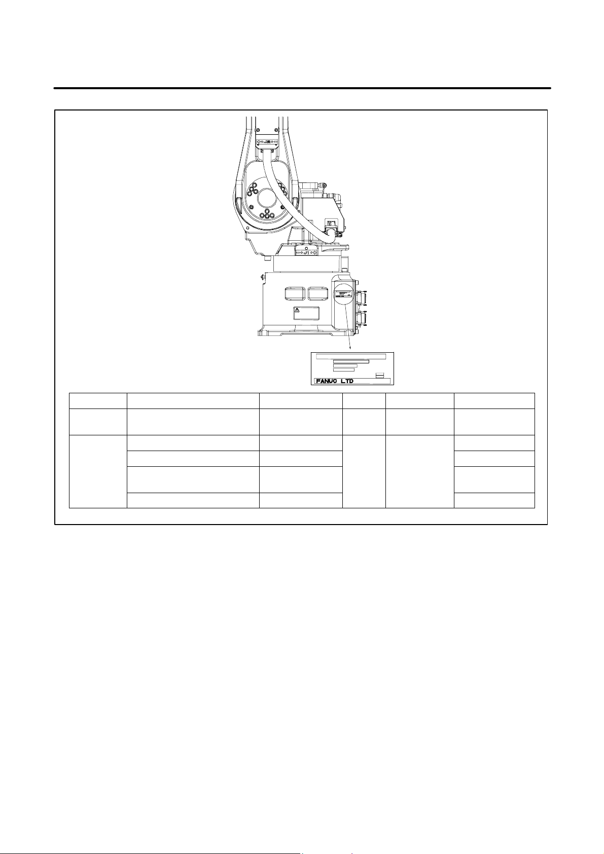
PREFACE
PRINT
PRODUCTION
MONTH
(1)
(3)
(4)
(2)
OSHINO–MURA,
YAMANASHI PREF. JAPAN
1)
TYPE
NO.
DATE
TOTAL WEIGHT WITH CONTROLLER : (5) kg
TOTAL WEIGHT WITHOUT CONTROLLER : (6) kg
No. (1) (2) (3) (4) (5)
CONTENTS MODEL TYPE No. DATE
FANUC Robot ARC Mate 120iB A05B–1216–B201 220 kg
PRINT
YEAR AND
MONTH
LETTERS
FANUC Robot M–16iB/20 A05B–1216–B202
FANUC Robot ARC Mate
120iB/10L
A05B–1216–B301
PRINT
SERIAL
NO.
FANUC Robot M–16iB/10L A05B–1216–B302
B–81765EN/01
WEIGHT
(Without controller)
220 kg
220 kg
220 kg
Positon of label indicating mechanical unit specification number
p–2
Page 22

B–81765EN/01
g
p
Specifications
PREFACE
Item
M–16iB/20
ARC Mate 120iB
M–16iB/10L
ARC Mate 120iB/10L
Type Articulated type
Controlled axes 6 axes (J1, J2, J3, J4, J5, J6)
Installation Floor, Upside–dowm (Wall & Angle mount) (Note 1)
Motion range
J1 axis 340° (5.93rad)
J2 axis 250° (4.36rad)
J3 axis 460° (8.03rad) 455° (7.94rad)
J4 axis 400° (6.98rad)
J5 axis 280° (4.89rad)
J6 axis 900° (15.71rad)
Maximum speed
J1 axis 165°/s (2.88rad/s)
J2 axis 165°/s (2.88rad/s)
J3 axis 175°/s (3.05rad/s)
J4 axis 350°/s (6.11rad/s)
J5 axis 340°/s (5.93rad/s)
J6 axis 520°/s (9.08rad/s)
Max. load capacity at wrist 20kg 10kg
Max. load capacity on J3 catting 12kg
Allowable load moment at wrist
Allowable load inertia at wrist
J4 axis 39.2N·m
(4.0kgf·m)
J5 axis 39.2N·m
(4.0kgf·m)
J6 axis 19.6N·m
(2.0kgf·m)
J4 axis 0.88kg·m2
(9.0kgf·cm·s
J5 axis 0.88kg·m2
(9.0kgf·cm·s
J6 axis 0.25kg·m2
(2.5kgf·cm·s
22.0N·m
(2.2kgf·m)
22.0N·m
(2.2kgf·m)
9.8N·m
(1.0kgf·m)
2
)
2
)
2
)
0.63kg·m2
(6.4kgf·cm·s
0.63kg·m2
(6.4kgf·cm·s
0.15kg·m2
(1.5kgf·cm·s
2
)
2
)
2
)
Drive method Electric servo drive by AC servo motor
Repeatability "0.08mm "0.10mm
Weight of mechanical unit 220kg
Installation environment Ambient temperature : 0 – 45°C
Ambient humidity : Normally :75%RH or less
: Short time 95%RH or less
(within 1 month)
(No dew or frost allowed)
Height : Up to 1,000 meters above the sea level
requires, no particular provision for
attitude.
Vibration : 0.5G (4.9m/s
2
) or less
Required facilities (when no option is provided) Average power consumption: 1.0 kW
Input power supply capacity: 3.0 kVA
NOTE
1 Under the installation condition within ( ), the J1 and J2 axis motion range will be limited.
p–3
Page 23

PREFACE
B–81765EN/01
Dust–proof/waterproof performance of M–16iB/20/10L
Normal specification
Wrist+J3 arm IP67
Other part IP54
NOTE
Definition of IP code
Definition of IP 67
6=Dust–tight
7=Protection from water immersion
Definition of IP 54
5=Dust–protected
4=Protection from splashing water
Performance of resistant chemicals and resistant solvents
(1) The robot (including severe dust/liquid protection model) cannot be
used with the following liquids because there is fear that rubber parts
(packing, oil seal, O ring etc.) will corrode.
(a) Organic solvents
(b) Coolant including chlorine / gasoline
(c) Amine washing lotion
(d) Acid, alkali and liquid causing rust
(e) Other liquids or solutions, that will harm NBR
(2) When the robots work in the environment, using water or liquid,
complete draining of J1 base must be done. Incomplete draining of
J1 base will make the robot break down.
p–4
Page 24

B–81765EN/01
PREFACE
RELATED MANUALS
Safety handbook B–80687EN
All persons who use the FANUC Robot and system designer must read and understand thoroughly this handbook
R–J3iB controller Setup and Operations
manual
SPOT TOOL
B–81464EN–1
HANDLING TOOL
B–81464EN–2
ARC TOOL
B–81464EN–3
SEALING TOOL
B–81464EN–4
Maintenance manual
B–81465EN
B–81465EN–1
(European
specification)
Mechanical unit Maintenance manual
FANUC Robot, ARC Mate
120iB, M–16iB
B–81765EN
For the FANUC Robot series, the following manuals are available:
Intended readers :
All persons who use FANUC Robot, system designer
Topics :
Safety items for robot system design, operation, maintenance
Intended readers :
Operator, programmer, maintenance person, system designer
Topics :
Robot functions, operations, programming, setup, interfaces, alarms
Use :
Robot operation, teaching, system design
Intended readers :
Maintenance person, system designer
Topics :
Installation, connection to peripheral equipment, maintenance
Use :
Installation, start–up, connection, maintenance
Intended readers :
Maintenance person, system designer
Topics :
Installation, connection to the controller, maintenance
Use :
installation, start–up, connection, maintenance
p–5
Page 25

B–81765EN/01
Table of Contents
SAFETY s–1. . . . . . . . . . . . . . . . . . . . . . . . . . . . . . . . . . . . . . . . . . . . . . . . . . . . . . . . . . . . . . . . .
PREFACE p–1. . . . . . . . . . . . . . . . . . . . . . . . . . . . . . . . . . . . . . . . . . . . . . . . . . . . . . . . . . . . . . . .
I. MAINTENANCE
1. CONFIGURATION 3. . . . . . . . . . . . . . . . . . . . . . . . . . . . . . . . . . . . . . . . . . . . . . . . . . . . .
1.1 J1–AXIS DRIVE MECHANISM 5. . . . . . . . . . . . . . . . . . . . . . . . . . . . . . . . . . . . . . . . . . . . . . . . . . . .
1.2 J2–AXIS DRIVE MECHANISM 6. . . . . . . . . . . . . . . . . . . . . . . . . . . . . . . . . . . . . . . . . . . . . . . . . . . .
1.3 J3–AXIS DRIVE MECHANISM 7. . . . . . . . . . . . . . . . . . . . . . . . . . . . . . . . . . . . . . . . . . . . . . . . . . . .
1.4 J4–AXIS DRIVE MECHANISM 8. . . . . . . . . . . . . . . . . . . . . . . . . . . . . . . . . . . . . . . . . . . . . . . . . . . .
1.5 J5– AND J6–AXIS DRIVE MECHANISMS 9. . . . . . . . . . . . . . . . . . . . . . . . . . . . . . . . . . . . . . . . . . .
1.6 SPECIFICATIONS OF THE MAJOR MECHANICAL UNIT COMPONENTS 10. . . . . . . . . . . . . . .
2. PREVENTIVE MAINTENANCE 11. . . . . . . . . . . . . . . . . . . . . . . . . . . . . . . . . . . . . . . . . .
2.1 DAILY INSPECTION 12. . . . . . . . . . . . . . . . . . . . . . . . . . . . . . . . . . . . . . . . . . . . . . . . . . . . . . . . . . . .
2.2 QUARTERLY INSPECTION 14. . . . . . . . . . . . . . . . . . . . . . . . . . . . . . . . . . . . . . . . . . . . . . . . . . . . . . .
2.3 YEARLY INSPECTION 14. . . . . . . . . . . . . . . . . . . . . . . . . . . . . . . . . . . . . . . . . . . . . . . . . . . . . . . . . . .
2.4 ONE– AND HALF–YEAR PERIODIC INSPECTION 14. . . . . . . . . . . . . . . . . . . . . . . . . . . . . . . . . . .
2.5 THREE–YEAR PERIODIC INSPECTION 14. . . . . . . . . . . . . . . . . . . . . . . . . . . . . . . . . . . . . . . . . . . .
2.6 MAINTENANCE TOOLS 15. . . . . . . . . . . . . . . . . . . . . . . . . . . . . . . . . . . . . . . . . . . . . . . . . . . . . . . . .
3. PERIODIC MAINTENANCE 16. . . . . . . . . . . . . . . . . . . . . . . . . . . . . . . . . . . . . . . . . . . . .
3.1 GREASING 17. . . . . . . . . . . . . . . . . . . . . . . . . . . . . . . . . . . . . . . . . . . . . . . . . . . . . . . . . . . . . . . . . . . . .
3.2 GREASE REPLACEMENT 19. . . . . . . . . . . . . . . . . . . . . . . . . . . . . . . . . . . . . . . . . . . . . . . . . . . . . . . .
3.3 REPLACING THE BATTERIES 22. . . . . . . . . . . . . . . . . . . . . . . . . . . . . . . . . . . . . . . . . . . . . . . . . . . .
4. TROUBLESHOOTING 23. . . . . . . . . . . . . . . . . . . . . . . . . . . . . . . . . . . . . . . . . . . . . . . . . .
4.1 OVERVIEW 24. . . . . . . . . . . . . . . . . . . . . . . . . . . . . . . . . . . . . . . . . . . . . . . . . . . . . . . . . . . . . . . . . . . .
4.2 TROUBLES AND CAUSES 25. . . . . . . . . . . . . . . . . . . . . . . . . . . . . . . . . . . . . . . . . . . . . . . . . . . . . . .
5. ADJUSTMENTS 28. . . . . . . . . . . . . . . . . . . . . . . . . . . . . . . . . . . . . . . . . . . . . . . . . . . . . . .
5.1 REFERENCE POSITION AND MOVING RANGE 29. . . . . . . . . . . . . . . . . . . . . . . . . . . . . . . . . . . . .
5.2 MASTERING 34. . . . . . . . . . . . . . . . . . . . . . . . . . . . . . . . . . . . . . . . . . . . . . . . . . . . . . . . . . . . . . . . . . .
5.2.1 General 34. . . . . . . . . . . . . . . . . . . . . . . . . . . . . . . . . . . . . . . . . . . . . . . . . . . . . . . . . . . . . . . . . . . . . . . . .
5.2.2 Resetting Alarms and Preparing for Mastering 35. . . . . . . . . . . . . . . . . . . . . . . . . . . . . . . . . . . . . . . . . . .
5.2.3 Mastering to a Fixture (Master Position Master) 36. . . . . . . . . . . . . . . . . . . . . . . . . . . . . . . . . . . . . . . . . .
5.2.4 Zero Position Mastering 41. . . . . . . . . . . . . . . . . . . . . . . . . . . . . . . . . . . . . . . . . . . . . . . . . . . . . . . . . . . .
5.2.5 Quick Mastering 44. . . . . . . . . . . . . . . . . . . . . . . . . . . . . . . . . . . . . . . . . . . . . . . . . . . . . . . . . . . . . . . . . .
5.2.6 Single Axis Mastering 46. . . . . . . . . . . . . . . . . . . . . . . . . . . . . . . . . . . . . . . . . . . . . . . . . . . . . . . . . . . . .
5.2.7 Mastering Data Entry 49. . . . . . . . . . . . . . . . . . . . . . . . . . . . . . . . . . . . . . . . . . . . . . . . . . . . . . . . . . . . . .
5.2.8 Confirming Mastering 51. . . . . . . . . . . . . . . . . . . . . . . . . . . . . . . . . . . . . . . . . . . . . . . . . . . . . . . . . . . . .
5.3 J5–AXIS GEAR BACKLASH ADJUSTMENTS 52. . . . . . . . . . . . . . . . . . . . . . . . . . . . . . . . . . . . . . .
5.4 BRAKE RELEASE 54. . . . . . . . . . . . . . . . . . . . . . . . . . . . . . . . . . . . . . . . . . . . . . . . . . . . . . . . . . . . . . .
c–1
Page 26

Table of Contents
B–81765EN/01
6. COMPONENT REPLACEMENT AND ADJUSTMENTS 55. . . . . . . . . . . . . . . . . . . . .
6.1 REPLACING THE J1–AXIS MOTOR
6.2 REPLACING THE J1–AXIS REDUCER 58. . . . . . . . . . . . . . . . . . . . . . . . . . . . . . . . . . . . . . . . . . . . .
6.3 REPLACING THE J2–AXIS MOTOR
6.4 REPLACING THE J2–AXIS REDUCER 62. . . . . . . . . . . . . . . . . . . . . . . . . . . . . . . . . . . . . . . . . . . . .
6.5 REPLACING THE J3–AXIS MOTOR
6.6 REPLACING THE J3–AXIS REDUCER 67. . . . . . . . . . . . . . . . . . . . . . . . . . . . . . . . . . . . . . . . . . . . .
6.7 REPLACING THE J4–AXIS MOTOR
6.8 REPLACING THE J4–AXIS GEARBOX 69. . . . . . . . . . . . . . . . . . . . . . . . . . . . . . . . . . . . . . . . . . . . .
6.9 REPLACING THE J5–AXIS MOTOR
6.10 REPLACING THE J5–AXIS GEAR 74. . . . . . . . . . . . . . . . . . . . . . . . . . . . . . . . . . . . . . . . . . . . . . . . .
6.11 REPLACING THE J6–AXIS MOTOR
M1
M2
60. . . . . . . . . . . . . . . . . . . . . . . . . . . . . . . . . . . . . . . . . .
M3
M4
M5
M6
AND REDUCER 76. . . . . . . . . . . . . . . . . . . . . . . . . . . .
7. PIPING AND WIRING 79. . . . . . . . . . . . . . . . . . . . . . . . . . . . . . . . . . . . . . . . . . . . . . . . . . .
7.1 PIPING DRAWING 80. . . . . . . . . . . . . . . . . . . . . . . . . . . . . . . . . . . . . . . . . . . . . . . . . . . . . . . . . . . . . .
7.2 WIRING DIAGRAMS 81. . . . . . . . . . . . . . . . . . . . . . . . . . . . . . . . . . . . . . . . . . . . . . . . . . . . . . . . . . . .
7.3 CABLE MOUNTING DIAGRAM 83. . . . . . . . . . . . . . . . . . . . . . . . . . . . . . . . . . . . . . . . . . . . . . . . . . .
8. CABLE REPLACEMENT 85. . . . . . . . . . . . . . . . . . . . . . . . . . . . . . . . . . . . . . . . . . . . . . . .
8.1 CABLE DRESSING 86. . . . . . . . . . . . . . . . . . . . . . . . . . . . . . . . . . . . . . . . . . . . . . . . . . . . . . . . . . . . . .
8.2 REPLACING CABLES 89. . . . . . . . . . . . . . . . . . . . . . . . . . . . . . . . . . . . . . . . . . . . . . . . . . . . . . . . . . .
56. . . . . . . . . . . . . . . . . . . . . . . . . . . . . . . . . . . . . . . . . . .
65. . . . . . . . . . . . . . . . . . . . . . . . . . . . . . . . . . . . . . . . . . .
68. . . . . . . . . . . . . . . . . . . . . . . . . . . . . . . . . . . . . . . . . . .
71. . . . . . . . . . . . . . . . . . . . . . . . . . . . . . . . . . . . . . . . . . .
II. CONNECTION
1. ROBOT OUTLINE DRAWING AND OPERATION AREA DIAGRAM 99. . . . . . . . . .
1.1 OUTLINE DRAWING AND OPERATION AREA DIAGRAM 100. . . . . . . . . . . . . . . . . . . . . . . . . . . .
2. MOUNTING DEVICES ON THE ROBOT 106. . . . . . . . . . . . . . . . . . . . . . . . . . . . . . . . . .
2.1 WRIST SECTION END EFFECTOR MOUNTING SURFACE 107. . . . . . . . . . . . . . . . . . . . . . . . . . . .
2.2 WRIST LOAD CONDITIONS 108. . . . . . . . . . . . . . . . . . . . . . . . . . . . . . . . . . . . . . . . . . . . . . . . . . . . . .
2.3 DEVICE MOUNTING SURFACES 110. . . . . . . . . . . . . . . . . . . . . . . . . . . . . . . . . . . . . . . . . . . . . . . . . .
2.4 SETTING THE SYSTEM VARIABLES FOR SHORTEST–TIME CONTROL 114. . . . . . . . . . . . . . .
2.5 END EFFECTOR AIR PIPING 117. . . . . . . . . . . . . . . . . . . . . . . . . . . . . . . . . . . . . . . . . . . . . . . . . . . . .
2.6 END EFFECTOR INPUT SIGNALS (RDI/RDO) 118. . . . . . . . . . . . . . . . . . . . . . . . . . . . . . . . . . . . . . .
2.7 CONNECTOR SPECIFICATIONS 119. . . . . . . . . . . . . . . . . . . . . . . . . . . . . . . . . . . . . . . . . . . . . . . . . .
3. TRANSPORTATION AND INSTALLATION 120. . . . . . . . . . . . . . . . . . . . . . . . . . . . . . . .
3.1 TRANSPORTATION 121. . . . . . . . . . . . . . . . . . . . . . . . . . . . . . . . . . . . . . . . . . . . . . . . . . . . . . . . . . . . .
3.2 STORING THE ROBOT 123. . . . . . . . . . . . . . . . . . . . . . . . . . . . . . . . . . . . . . . . . . . . . . . . . . . . . . . . . .
3.3 INSTALLATION 124. . . . . . . . . . . . . . . . . . . . . . . . . . . . . . . . . . . . . . . . . . . . . . . . . . . . . . . . . . . . . . . .
3.4 MAINTENANCE CLEARANCE 128. . . . . . . . . . . . . . . . . . . . . . . . . . . . . . . . . . . . . . . . . . . . . . . . . . .
3.5 ASSEMBLING THE ROBOT FOR INSTALLATION 131. . . . . . . . . . . . . . . . . . . . . . . . . . . . . . . . . . .
3.6 AIR PIPING 132. . . . . . . . . . . . . . . . . . . . . . . . . . . . . . . . . . . . . . . . . . . . . . . . . . . . . . . . . . . . . . . . . . . .
c–2
Page 27

B–81765EN/01
3.7 INSTALLATION CONDITIONS 134. . . . . . . . . . . . . . . . . . . . . . . . . . . . . . . . . . . . . . . . . . . . . . . . . . . .
Table of Contents
APPENDIX
A. SPARE PARTS LISTS 137. . . . . . . . . . . . . . . . . . . . . . . . . . . . . . . . . . . . . . . . . . . . . . . . . .
B. INTERNAL MECHANICAL UNIT CONNECTION DIAGRAMS 143. . . . . . . . . . . . . . .
C. PERIODIC INSPECTION TABLE 146. . . . . . . . . . . . . . . . . . . . . . . . . . . . . . . . . . . . . . . . .
D. MOUNTING BOLT TORQUE LIST 148. . . . . . . . . . . . . . . . . . . . . . . . . . . . . . . . . . . . . . .
c–3
Page 28

Page 29

I. MAINTENANCE
Page 30

Page 31

B–81765EN/01
1
J4–axis
AC servo motor
(M4)
J3–axis
AC servo
motor (M3)
1. CONFIGURATIONMAINTENANCE
CONFIGURATION
Fig. 1 shows the configuration of the mechanical unit.
J3–axis arm
J3–axis casing
J5–axis AC servo motor (M5)
J1–axis
AC servo
motor (M1)
Wrist unit
J6–axis AC servo motor (M6)
J2–axis arm
J2–axis base
J1–axis base
J2–axis AC servo motor (M2)
Fig 1 (a) Mechanical unit configuration (ARC Mate 120iB, M–16iB/20)
3
Page 32

1. CONFIGURATION
J4–axis
AC servo
motor (M4)
J3–axis
AC servo
motor for (M3)
J1–axis
AC servo
motor (M1)
MAINTENANCE
J5–axis AC servo motor (M5)
J6–axis
AC servo motor
(M6)
J2–axis
AC servo motor (M2)
J3–axis arm
J2–axis arm
J2–axis base
J1–axis base
B–81765EN/01
J3–axis
casing
Wrist unit
Fig 1 (b) Mechanical unit configuration (ARC Mate 120iB/10L, M–16iB/10L)
4
Page 33

B–81765EN/01
1. CONFIGURATIONMAINTENANCE
1.1
J1–AXIS DRIVE MECHANISM
J1–axis AC servo motor
α M8/4000i
J1–axis reducer
Fig. 1.1 shows the J1–axis drive mechanism.
The J1–axis drive mechanism is configured in such a way that the J2–axis
base is rotated by reducing the rotation speed of an AC servo motor with
a reducer.
The J2–axis base is supported on the J1–axis base through the reducer.
J2–axis base
J1–axis base
Fig 1.1 J1–axis drive mechanism
5
Page 34

1. CONFIGURATION
MAINTENANCE
B–81765EN/01
1.2
J2–AXIS DRIVE MECHANISM
J2–axis AC
servo motor
α M8/4000i
Fig. 1.2 shows the J2–axis drive mechanism. The J2–axis drive
mechanism is configured in such a way that the J2–axis arm is rotated by
reducing the rotation speed of an AC servo motor with a reducer.
The J2–axis arm is supported on the J2–axis base through the reducer.
J2–axis base
J2–axis arm
Fig 1.2 J2–axis drive mechanism
J2–axis reducer
6
Page 35

B–81765EN/01
1. CONFIGURATIONMAINTENANCE
1.3
J3–AXIS DRIVE MECHANISM
Fig. 1.3 shows the J3–axis drive mechanism. The J3–axis drive
mechanism is configured in such a way that the J3–axis casing is rotated
by reducing the rotation speed of an AC servo motor with a reducer.
The J3–axis casing is supported on the J2–axis arm through the reducer.
J3–axis
reducer
J3–axis AC
servo motor
α M2/5000i
J3–axis casing
J2–axis arm
Fig 1.3 J3–axis drive mechanism
7
Page 36

1. CONFIGURATION
MAINTENANCE
B–81765EN/01
1.4
J4–AXIS DRIVE MECHANISM
Fig. 1.4 shows the J4–axis drive mechanism. The J4–axis drive
mechanism is configured in such a way that the J3–axis arm is rotated by
reducing the rotation speed of an AC servo motor with a two–stage gear.
J3–axis arm
Final gear
Second gear
Input gear
J3–axis
casing
J4–axis AC
servo motor
α M2/5000i
Fig 1.4 J4–axis drive mechanism
8
Page 37

B–81765EN/01
1. CONFIGURATIONMAINTENANCE
1.5
J5– AND J6–AXIS DRIVE MECHANISMS
J5–axis AC servo motor
β M0.5/4000
J3–axis
arm
Fig. 1.5 shows the J5– and J6–axis drive mechanisms. The J5–axis drive
mechanism is configured in such a way that the J6–axis unit is rotated by
reducing the rotation speed of an AC servo motor with a three–stage gear.
The J6–axis drive mechanism is configured in such a way that the output
flange is rotated by reducing the rotation speed of an AC servo motor with
a reducer.
J6–axis unit
J6–axis AC
servo motor
β M0.5/4000
Output
flange
Input gear
Second gear
J6–axis
reducer
Final gear
Third gear
Fig 1.5 J5– and J6–axis drive mechanisms
9
Page 38

1. CONFIGURATION
MAINTENANCE
B–81765EN/01
1.6
SPECIFICATIONS OF THE MAJOR MECHANICAL UNIT COMPONENTS
1) Motors
M–16iB/20, ARC Mate 120iB,
M–16iB/10L, ARC Mate 120iB/10L
Motor Specification Model Axis
M1, M2 A06B-0235-B605 M8/4000i J1, J2
M3, M4 A06B-0212-B605 M2/5000i J3, J4
M5, M6 A06B-0115-B275#0008 M0.5/4000 J5, J6
2) Reducers
Specification Axis
A97L-0218-0303#37 J1
A97L-0218-0304#175 J2
A97L-0218-0305#37 J3
A97L-0218-0306 J6
3) Gears
Specification Axis
A290-7216-X511 J5
A290-7216-V501 J5
A290-7216-V502 J5
A290-7216-X514 J5
4) J4–axis gearbox
Specification
A290-7216-K401
5) Wrist flange
Specification
A290-7216-V503
6) Stoppers
Specification Axis
A290-7216-X241 J1
A290-7216-X323 J2
Note) 340° stopper
A290-7215-X323 J3
10
Page 39

B–81765EN/01
2
2. PREVENTIVE MAINTENANCEMAINTENANCE
PREVENTIVE MAINTENANCE
Performing daily inspection, periodic inspection, and maintenance can
keep the performance of robots in a stable state for a long period.
NOTE
The periodic maintenance procedures described in this
chapter assume that the FANUC robot is used for up to 3840
hours a year. When using the robot beyond this total
operating time, correct the maintenance frequencies shown
in this chapter by calculation in proportion to the difference
between the actual operating time and 3840 hours/year.
11
Page 40

2. PREVENTIVE MAINTENANCE
MAINTENANCE
B–81765EN/01
2.1
DAILY INSPECTION
Clean and maintain each component of robots during everyday system
operations. At the same time, check the components to see if there is a
crack or break in them. Also check and maintain the following items as
required.
a) Before automatic operation
No. Inspection item Inspection procedure
1 Pneumatic pressure
check
2
For
machines
with a
three–piece
pneumatic
option
Check on the amount of
oil mist
Make a pneumatic pressure
check, using the three–piece
pneumatic option shown in Fig.
2.1.
If the measured pneumatic
pressure does not fall in the
range between 0.5 and 0.7 MPa
(5 and 7 kg/cm
ments, using the regulator pressure setting handle.
Put the pneumatic pressure
system in operation and check
the amount of oil dripping. If the
measured amount of oil dripping
does not meet the rating (one
drop/10 to 20 seconds), make
adjustments, using the oil adjustment knob. The oiler becomes empty after 10 to 20 days
of normal operation.
2
), make adjust-
3 Check on the amount of
oil
4 Check for leakage from
the piping
5 Whether cables are abnormal
Mechanical unit
6 Battery voltage check Make sure that when the power
7 Whether there is any abnormal vibra-
tion, noise, or heat generation in motors
8 Whether there is a change to position-
ing precision
Check to see if the amount of oil
in the three–piece option is within the rated level shown in Fig.
2.1.
Check to see if a joint or hose
leaks.
If you find a problem, tighten the
joint or replace any defective
component.
See Chapter 8.
is turned on, the BLAL alarm
has not been raised. If the BLAL
alarm has been raised, replace
the battery as directed in Section 3.3.
Check that each axis is running
smoothly.
Check to see if there is any displacement from the previous
position and there are variations
in the stop position.
12
Page 41

B–81765EN/01
2. PREVENTIVE MAINTENANCEMAINTENANCE
No. Inspection procedureInspection item
9 Reliable operation of peripheral equip-
ment
10 Check on the operation of the J2– and
J3–axis brakes.
Oiler’s oil inlet
Filter
Regulator pressure setting handle
Fig 2.1 Three–piece pneumatic option
Pressure gauge
Check to see if the machine operates exactly according to
directions from the robot and
peripheral equipment.
See Section 4.2.
Oiler adjustment knob
Check oiler’s oil level
Oiler
b) After automatic operation
Once you are finished with automatic operation, bring the robot to its
reference position, and turn it off.
No. Inspection item Inspection procedure
1 Component cleaning
and inspection
Clean and maintain each component. At the
same time, check the components to see if
there is a crack or break in them.
13
Page 42

2. PREVENTIVE MAINTENANCE
MAINTENANCE
B–81765EN/01
2.2
QUARTERLY INSPECTION
2.3
YEARLY INSPECTION
2.4
ONE– AND
HALF–YEAR
PERIODIC
INSPECTION
Inspect the following items at regular intervals of three months. Increase
the locations and the frequency of inspection if the conditions under
which the robot is used and the environment in which it runs require so.
No. Inspection item Inspection procedure
1 Loose connector Check that the motor connectors or other con-
nectors are not loose.
2 Loose bolt Check that the cover retaining bolts or external
bolts are not loose.
3 Debris removal Remove any spatter, debris, and dust from the
mechanical unit.
Inspect the following item at regular intervals of one year.
No. Inspection item Inspection procedure
1 J6 Greasing See Section 3.1.
Perform the following inspection/maintenance item at regular intervals of
one year and half.
No. Inspection item Inspection procedure
1 Battery replacement Replace the battery in the mechanical unit.
(See Section 3.3.)
2.5
THREE–YEAR PERIODIC INSPECTION
No. Inspection item Inspection procedure
1 J1–J5 Grease replacement See Section 3.2.
14
Page 43

B–81765EN/01
2. PREVENTIVE MAINTENANCEMAINTENANCE
2.6
MAINTENANCE TOOLS
You should have the following instruments and tools ready for
maintenance.
a) Measuring instruments
Instrument Condition Use
Dial gauge 1/100mm For positioning precision and backlash
measurement
Calipers 150mm
b) Tools
Phillips screwdrivers (large, medium, and small sizes)
Flat–blade screwdrivers (large, medium, and small sizes)
Box wrenches (M3 to M6)
Allen wrenches (M3 to M16)
Torque wrench
Long T wrenches (M5 and M6)
Adjustable wrenches (medium and small sizes)
Pliers
Long–nose pliers
Cutting pliers
Both–ended wrench
Grease gun
C–ring pliers
Flashlight
15
Page 44

3. PERIODIC MAINTENANCE
PERIODIC MAINTENANCE
3
MAINTENANCE
B–81765EN/01
16
Page 45

B–81765EN/01
3. PERIODIC MAINTENANCEMAINTENANCE
3.1
GREASING
Following is the greasing procedure for J6–axis reducer.
When greasing the robot, keep its power turned off.
i) Replenish the J6–axis reducer with grease every 12 months or after
3840 hours of operation.
ii) See Fig. 3.1 and Table 3.1 for greasing points and the method.
Table. 3.1 Greasing points
Greasing
No.
1 J6–axis
point
reducer
Specified
grease
Moly White
RE No.00
(Specification:
A97L-0040-0119)
Amount
of
grease
40cc Replace the flat–head bolts
Greasing method
and sealing washers of the
J6–axis grease inlet and outlet, and attach the supplied
grease nipple of the J6–axis to
the grease inlet of the J6–axis.
After greasing, remove the
grease nipple, and attach the
flat–head bolts and sealing
washers to the grease inlet
and outlet.
CAUTION
If you grease incorrectly, the pressure in the grease bath
may increase steeply, leading to a broken seal, which will
eventually cause grease leakage or malfunction.
When greasing, be sure to follow the cautions stated in
Section 3.2.
17
Page 46

3. PERIODIC MAINTENANCE
J5–axis gear box
Bolt+Seal washer
(Bleed hole)
MAINTENANCE
J5–axis gear box
Bolt+Seal washer
(Greasing point)
J6–axis reducer
Bolt+Seal washer
(Bleed hole)
J6–axis reducer
Bolt+Seal washer
(Greasing point)
B–81765EN/01
J4–axis gear box
Bolt+Seal washer
(Bleed hole)
J3–axis
reducer
Plug
(Bleed hole)
J1–axis
reducer
Seal bolt
(Bleed hole)
J1–axis reducer
Grease nipple
(Greasing point)
J2–axis
reducer
Seal bolt
(Bleed hole)
J4–axis gear box
Grease nipple
(Greasing point)
J3–axis reducer
Grease nipple
(Greasing point)
J2–axis reducer
Grease nipple
(Greasing point)
Fig 3.1 Greasing points
18
Page 47

B–81765EN/01
grease to be
ture when
(S
ificati
3. PERIODIC MAINTENANCEMAINTENANCE
3.2
GREASE REPLACEMENT
Follow the procedure stated below to replace the grease in the J1–, J2–,
and J3–axis reducers and the J4– and J5–axis gearboxes once every three
years or after 11,520 hours of operation. See Fig. 3.1 for greasing points.
1) Remove the seal bolts from the J1–, J2–axis grease outlets shown in
Fig. 3.1. Also remove the plug of J3–axis grease outlet, the flat–bolts
and sealing washers from the J4– and J5–axis grease outlets.
2) Uncap the grease nipples at the J1–, J2–, J3–, and J4–axis grease inlets.
When the J5–axis grease is supplied remove the flat–head bolt from
the J5–axis grease inlet and attach the grease nipple to the J3–axis or
J4–axis grease inlet.
3) Supply the grease specified in Table 3.2 to the J1–, J2–, and J3–axis
reducers, and J4– and J5–axis gearboxes through their respective
grease nipples. Keep greasing until the new grease pushes out the old
grease and comes out from each grease outlet. Ensure that the amount
of the newly supplied grease equals the amount of the drained grease
so that the grease bath will not become full.
4) Wind sealing tape around the J1–, J2–axis seal bolts and J3–axis plug
you removed, and attach them to the respective grease outlets.
5) Attach the J4– and J5–axis flat–head bolts and the J4– and J5–axis
sealing washers to the respective grease inlets and outlets.
6) When finally returning the grease nipple used at another location to the
original position, be sure to wind sealing tape around the threads part.
In addition, be sure to cap the grease nipple for each axis.
Table. 3.2 Grease to be replaced at regular intervals of three years
Specified grease Amount of
Kyodo Yushi
J1–axis reducer
J2–axis reducer
J3–axis reducer 550cc J3=0°
J4–axis gearbox 1030cc J3=0°
J5–axis gearbox 400cc J3=–90°
Moly White RE No.00
pec
A98L-0040-0119#2.4KG)
on:
applied (cc)
980cc –
550cc J2=0°
Robot pos-
greased
19
Page 48

3. PERIODIC MAINTENANCE
MAINTENANCE
B–81765EN/01
CAUTION
If you grease incorrectly, the pressure in the grease bath will
increase, leading to a broken seal, which will eventually cause
grease leakage or malfunction.
When greasing, be sure to follow the cautions stated below.
1 Before starting greasing, open the grease outlets (remove
bolts and the like from the grease outlets).
2 Using a manual greasing pump, grease gently and slowly.
3 Avoid using a pneumatic pump driven from a factory
pneumatic line as much as possible.
If you cannot avoid using it, observe a greasing speed of 15
2
cc/s or lower and a pressure of 75 kgf/cm
or lower.
4 Be sure to use the specified grease. Otherwise, damage to
reducers or a similar abnormality may occur.
5 Before capping the grease outlets, make sure that a grease
flow from the grease outlet has stopped (the remaining
pressure has been released).
6 Wipe off any grease from the floor and robot completely, so
no one will slip on it.
20
Page 49

B–81765EN/01
3. PERIODIC MAINTENANCEMAINTENANCE
When replacing or supplying grease, keep the robot in the posture shown
in Fig. 3.2.
J1 to J4–axis Posture
J5–axis Posture
Fig 3.2 Robot posture for greasing
21
Page 50

3. PERIODIC MAINTENANCE
MAINTENANCE
B–81765EN/01
3.3
REPLACING THE BATTERIES
The position data of each axis is preserved by the backup batteries. The
batteries need to be replaced every 1.5 year. Also use the following
procedure to replace when the backup battery voltage drop alarm occurs.
1 Keep the power on. Press the EMERGENCY STOP button to
prohibit the robot motion.
NOTE
Never turn off the robot controller power when replacing the
batteries. Otherwise, all position data will be lost and
mastering will be required again.
2 Remove the battery case cap.
3 Take out the old batteries from the battery case.
4 Insert new batteries into the battery case.
Pay attention to the direction of batteries.
5 Close the battery case cap.
22
Battery spec. : A98L–0031–0005
(1.5V size–D)
Fig.3.3 Replacing Batteries
Page 51

4. TROUBLESHOOTING
TROUBLESHOOTING
4
MAINTENANCE
B–81765EN/01
23
Page 52

B–81765EN/01
4. TROUBLESHOOTINGMAINTENANCE
4.1
OVERVIEW
A problem with a mechanical unit may occur due to a combination of
multiple causes. It is difficult to find out the true cause, and an incorrect
measure may make the problem worse. When troubleshooting, it is
important to get hold of the situation of any error accurately and take a
correct measure.
24
Page 53

4. TROUBLESHOOTING
MAINTENANCE
B–81765EN/01
4.2
TROUBLES AND CAUSES
Table 4.2 (a) lists the major troubles in the mechanical unit and their
causes. If you cannot find a cause accurately or do not know what measure
to take, please contact FANUC.
Note, however, that lower values of backlash and drop levels listed,
respectively, in Table 4.2 (b), (d) and Table 4.2 (c), (e) are not abnormal.
Table 4.2 (a) Major troubles and causes (1/3)
Symptom Cause Measure Remark
BZAL alarm issued
(battery zero)
Incorrect positioning Something hit the robot. Correct the taught point.
The voltage of the memory
backup battery has dropped.
Broken pulse coder signal
cable
Robot is not hanged down to
floor correctly.
Peripheral equipment has
shifted.
Load too heavy Reduce the load.
Replace the battery, and perform simplified mastering.
Replace the cable, and perform simplified mastering.
Tighten hanging bolts or
replace if needed.
Tighten hanging bolts or
replace if needed.
Limit the operating condition.
See Section 3.3.
See Section 5.3.
See Section 8.2.
See Section 5.3.
See Section 3.2 of Part II,
“Connection”.
Load on the wrist:
Refer to “Descriptions”.
Peripheral equipment:
See Section 2.2 of Part II,
“Connection”.
Incorrect parameter setting Correct it. Refer to “Operator’s Manual”.
Broken cable Replace the cable. See Section 8.2.
Pulse coder error Replace the motor. See Sections 6.1 to 6.11.
Backlash in the mechanical
unit –– see the next section.
25
Page 54

B–81765EN/01
Symptom Cause Measure Remark
4. TROUBLESHOOTINGMAINTENANCE
Table 4.2 (a) Major troubles and causes (2/3)
Vibration The robot is not firmly
mounted.
The floor is vibrating (especially when the robot is
installed on the second floor
or above).
Load too heavy Reduce the load.
Servo is not correctly adjustment.
Broken cable Replace the cable. See Section 8.2.
Robot not grounded Ground the robot. Refer to “Maintenance Manu-
Defective motor Replace the motor. See Sections 6.1 to 6.11.
Defective axis printed–circuit
board
Defective reducer Replace the reducer. See Sections 6.2 to 6.11.
Invalid time constant setting Change the time constant. Refer to “Operator’s Manual”.
Backlash in the mechanical
unit –– see the next section.
Tighten the mounting screws. See Section 3.2 of Part II,
“Connection”.
Re–examine the location of
installation.
Load on the wrist:
Limit the operating condition
Adjust the servo section. Contact FANUC.
Replace the axis printed–circuit board.
Refer to “Descriptions”.
Peripheral equipment:
See Section 2.2 of Part II,
“Connection”.
al for the Controller”.
Refer to “Maintenance Manual for the Controller”.
Backlash or wobbling Loose screw or pin Tighten it (and apply Loctite
to it if specified so)
Defective reducer Replace the reducer. See Sections 6.2 to 6.11.
Gear is not correctly adjustment.
Worn gear Adjust or replace the gear. Contact FANUC.
Worn bearing Replace the bearing. Contact FANUC.
Broken casting or other part Replace the broken compo-
Abnormal sound Insufficient grease for gear or
reducer
Foreign matter in gear or reducer
Gear is not correctly adjustment.
Worn gear Adjust or replace the gear. Contact FANUC.
Worn bearing Replace the bearing. Contact FANUC.
Servo section maladjustment Adjust the servo section. Contact FANUC.
Adjust the gear. See Section 5.7.
nent.
Apply grease. See Sections 3.1 and 3.2.
Wash the gear or reducer
and apply grease.
Adjust the gear. Contact FANUC.
Contact FANUC.
See Sections 6.2 to 6.11, 3.1,
and 3.2.
26
Page 55

4. TROUBLESHOOTING
Symptom Cause Measure Remark
MAINTENANCE
Table 4.2 (a) Major troubles and causes (3/3)
B–81765EN/01
Abnormal heat generation Insufficient grease for gear or
reducer
Non–specified grease used Replace the grease. See Sections 3.1 and 3.2.
Load too heavy Reduce the load.
Gear maladjustment Adjust the gear. Contact FANUC.
Invalid time constant setting Change the time constant
Arm drop at power turn–off Too large a brake gap Replace the motor. See Sections 6.1 to 6.11.
Brake drive relay contact deposition
Grease leakage Deteriorated or broken
O–ring, oil seal, or gasket
Broken casting or other part Replace the broken compo-
Loose screw Tighten it.
Table 4.2 (b) Permissible Backlash Value (ARC Mate 120iB, M–16iB/20)
Apply grease. See Sections 3.1 and 3.2.
Load on the wrist:
Limit the operating condition.
setting.
Replace the relay Refer to “Maintenance Manu-
Replace the O–ring, oil seal,
or gasket.
nent.
Refer to “Descriptions”.
Peripheral equipment:
See Section 2.2 of Part II,
“Connection.”
Refer to “Operator’s Manual”.
al for the Controller”.
Contact FANUC.
Contact FANUC.
J1 J2 J3 J4 J5 J6
Angle conversion (arc–min) 2.5 2.5 2.5 3.0 4.5 3.0
Displacement conversion (mm) 1.21 0.56 0.54 0.17 0.26 0.17
Distance between the rotation
center and dial indicator (mm)
Table 4.2 (c) Allowable arm drop (ARC Mate 120iB, M–16iB/20)
At power turn–off time
At emergency stop time 5mm
Table 4.2 (d) Permissible Backlash Value (ARC Mate 120iB/10L, M–16iB/10L)
Angle conversion (arc–min) 2.5 2.5 2.5 3.0 4.5 3.0
Displacement conversion (mm) 1.37 0.56 0.70 0.17 0.26 0.17
Distance between the rotation
center and dial indicator (mm)
Table 4.2 (e) Allowable arm drop (ARC Mate 120iB/10L, M–16iB/10L)
1660 770 740 200 200 200
5mm
J1 J2 J3 J4 J5 J6
1880 770 960 200 200 200
At power turn–off time 5mm
At emergency stop time 5mm
27
Page 56

B–81765EN/01
5
5. ADJUSTMENTSMAINTENANCE
ADJUSTMENTS
Each part of the robot mechanical units is set to the best condition before
the robot is shipped to the customer. The customer does not need to make
adjustments on the robot when it is delivered.
If a mechanical unit of the robot has a large backlash because of a
long–term use or component replacement, make adjustments using to this
section.
28
Page 57

5. ADJUSTMENTS
MAINTENANCE
B–81765EN/01
5.1
REFERENCE POSITION AND MOVING RANGE
1) Reference position and operation limit
Each controlled axis is provided with a reference position and
operation limit.
A state in which a controlled axis has reached its operation limit is
known as overtravel (OT). For each axis, an overtravel condition can
be detected at the both ends of it. As long as the robot does not
encounter a servo section error or system error that causes a reference
position to be lost, the robot is controlled in such a way that it will not
go out of its operation area.
Fig. 5.1 (a) to Fig. 5.1 (g) show the reference position and operation
area (stroke) of each axis and their mechanical stopper positions.
Fig. 5.1 (h) shows the operation directions (+/– directions) of each
axis.
Stroke
Stroke endStroke end
Mechanical stopper Mechanical stopper
ARC Mate 120iB, M–16iB/20, ARC Mate 120iB/10L, M–16iB/10L
Note)Motion limit is restricted by the
J3–axis position
Mechanical
stopper
ARC Mate 120iB, M–16iB/20, ARC Mate 120iB/10L, M–16iB/10L
Fig 5.1 (a) J1–axis swiveling (typically 340°)
Stroke
Stroke end
Stroke end
Mechanical stopper
Fig 5.1 (b) J2–axis rotation
29
Page 58

B–81765EN/01
Note)Motion limit is restricted by the
J2–axis position
Stroke end
Fig 5.1 (c) J3–axis rotation
ARC Mate 120iB, M–16iB/20
Note)Motion limit is restricted by the
J2–axis position
5. ADJUSTMENTSMAINTENANCE
Stroke
Stroke end
Stroke
Stroke end
Stroke end
Fig 5.1 (d) J3–axis rotation
ARC Mate 120iB/10L, M–16iB/10L
30
Page 59

5. ADJUSTMENTS
MAINTENANCE
Stroke
Stroke endStroke end
Note)J4–axis doesn’t have the mechanical stopper.
Fig 5.1 (e) J4–axis rotation
ARC Mate 120iB, M–16iB/20, ARC Mate 120iB/10L, M–16iB/10L
B–81765EN/01
Stroke end
Mechanical stopper
Stroke end
Mechanical stopper
Fig 5.1 (f) J5–axis wrist rotation
ARC Mate 120iB, M–16iB/20, ARC Mate 120iB/10L, M–16iB/10L
Stroke
31
Page 60

B–81765EN/01
5. ADJUSTMENTSMAINTENANCE
Stroke
Stroke endStroke end
Fig 5.1 (g) J6–axis wrist rotation
ARC Mate 120iB, M–16iB/20, ARC Mate 120iB/10L, M–16iB/10L
J3–axis arm
Interference angle
J2–axis arm
Interference angle
Stroke end
Mechanical stopper
Fig 5.1 (h) J2/J3 limit interference angle
ARC Mate 120iB, M–16iB/20, ARC Mate 120iB/10L, M–16iB/10L
Stroke end
Mechanical stopper
32
Page 61

5. ADJUSTMENTS
MAINTENANCE
B–81765EN/01
J6–axis
–
J4–axis
+
–
+
–
J5–axis
J3–axis
+
–
+
–
+
J1–axis
+
Fig 5.1 (i) Operation directions of each axis
ARC Mate 120iB, M–16iB/20
J2–axis
–
J6–axis
–
J4–axis
J3–axis
–
+
+
–
+
J5–axis
–
+
J1–axis
Fig 5.1 (j) Operation directions of each axis
ARC Mate 120iB/10L, M–16iB/10L
+
–
J2–axis
–
+
33
Page 62

B–81765EN/01
5. ADJUSTMENTSMAINTENANCE
5.2
MASTERING
5.2.1
General
Mastering is an operation performed to associate the angle of each robot
axis with the pulse count value supplied from the absolute pulse coder
connected to the corresponding axis motor. To be specific, mastering is
an operation for obtaining the pulse count value corresponding to the zero
position.
The current position of the robot is determined according to the pulse
count value supplied from the pulse coder on each axis.
Mastering is factory–performed. It is unnecessary to perform mastering
in daily operations. However, mastering becomes necessary after:
D Motor replacement.
D Pulse coder replacement.
D Reducer replacement.
D Cable replacement.
D Batteries for pulse count backup in the mechanical unit have gone dead.
NOTE
Robot data (including mastering data) and pulse coder data
are backed up by their respective backup batteries. Data will
be lost if the batteries go dead. Replace the batteries in the
control and mechanical units periodically. An alarm will be
issued to warn the user of a low battery voltage.
Mastering method
Table 5.2.1 Types of Mastering
Jig position mastering
Zero-position mastering (eye mark mastering)
Quick mastering This is performed at a user–specified position. The cor-
One-axis mastering This is performed for one axis at a time. The mastering
Mastering data entry Mastering data is entered directly.
This is performed using a mastering jig before the
machine is shipped from the factory.
This is performed with all axes set at the 0–degree position. A zero–position mark (eye mark) is attached to
each robot axis. This mastering is performed with all
axes aligned to their respective eye marks.
responding count value is obtained from the rotation
speed of the pulse coder connected to the relevant
motor and the rotation angle within one rotation. Quick
mastering uses the fact that the absolute value of a rotation angle within one rotation will not be lost.
position for each axis can be specified by the user. This
is useful in performing mastering on a specific axis.
Once mastering is performed, it is necessary to carry out positioning, or
calibration. Positioning is an operation in which the control unit reads the
current pulse count value to sense the current position of the robot.
When the battery backup of the pulse coder is interrupted by cable
replacement, you can perform quick mastering to perform calibration to
the original position. When the phase of the pulse coder is changed
mechanically as a result of replacement of the motor, reducer, and so forth,
you cannot perform quick mastering. In this case, you must perform jig
position mastering to calibrate the position accurately.
34
Page 63

5. ADJUSTMENTS
MAINTENANCE
B–81765EN/01
NOTE
If mastering is performed incorrectly, the robot may behave
unexpectedly. This is very dangerous. So, the positioning
screen is designed to appear only when the
$MASTER_ENB system variable is 1 or 2. After performing
positioning, press F5 [DONE] on the positioning screen.
The $MASTER_ENB system variable is reset to 0
automatically, thus hiding the positioning screen.
5.2.2
Resetting Alarms and
Preparing for
Mastering
Alarm displayed
Procedure
Preparing the Robot for
Mastering
Step
Before performing mastering because a motor is replaced, it is necessary
to release the relevant alarm and display the positioning menu.
“Servo 062 BZAL” or “Servo 075 Pulse mismatch”
1 To reset the “Servo 062 BZAL” alarm, follow steps 1 to 7.
1 Press MENUS.
2 Press NEXT and select [SYSTEM].
3 Press F1 [TYPE], and select [Variables] from the menu.
4 Place the cursor on $MCR then press the enter key.
5 Place the cursor on $SPC_RESET, then press F4 [TRUE]. The
message “TRUE” appears and disappears immediately.
6 If the message “TRUE” did not appear, retry by repeating the
above step several times.
7 Switch the controller power off and on again.
2 To reset the “Servo 075 Pulse mismatch” alarm, follow steps 1 to 3.
1 When the controller power is switched on again, the message
“Servo 075 Pulse mismatch” appears again.
2 Rotate the axis for which the message mentioned above has
appeared through 10 in either direction.
3 Press [FAULT RESET]. The alarm is reset.
3 Display the mastering menu by following steps 1 to 6.
1 Press MENUS.
2 Press NEXT and select [SYSTEM].
3 Press F1 [TYPE], and select [Variables] from the menu.
4 Place the cursor on $MASTER_ENB, then key in “1” and press
[ENTER].
5 Press F1 [TYPE], and select [Master/Cal] from the menu.
6 Select the desired mastering type from the [Master/Cal] menu.
35
Page 64

B–81765EN/01
5. ADJUSTMENTSMAINTENANCE
5.2.3
Mastering to a Fixture
(Master Position
Master)
Mounting the
mastering jig
Fixture mastering is performed using a mastering jig. This mastering is
carried out in the predetermined jig position.
Fixture mastering is accurate because a dedicated mastering jig is used.
Fixture mastering is factory–performed. It is unnecessary to perform it in
daily operations.
When mastering the robot, arrange the robot to meet the following
conditions.
D Make the robot mounting base horizontal within 1 mm.
D Remove the hand and other parts from the wrist.
D Set the robot in the condition protected from an external force.
NOTE
When the robot is being subjected to mastering, it does not
make a axis limit check. Pay sufficient attention to the
operation of the robot axes.
Install the mastering jig. The mastering jig used is common to the
M–16iB/20, ARC Mate 120iB, M–16iB/10L, and ARC Mate 120iB/10L.
1) Assembling the fixture base
Assemble the fixture base B and C as shown in Fig.5.2.3 (a).
Mastering
fixture B
Mastering
fixture C
Fig.5.2.3 (a) Assembling fixture base
2) Mounting dial indicator.
As shown in Fig. 5.2.3 (b), mount the dial indicator on the fixture base.
Adjust the dial gauge to 3.00 mm using the calibration block, and
tighten it with M5 bolt as shown in Fig.5.2.3 (b). (Do not tighten the
bolt too strongly or the dial indicator will be broken.)
36
Page 65

5. ADJUSTMENTS
MAINTENANCE
B–81765EN/01
Gauge Block
Gauge B
Gauge C
Gauge F
Gauge A
0
3
Gauge D
Gauge E
Fig.5.2.3 (b) Mounting dial indicator
3) Mounting fixture base
Mount the fixture on the J1–axis base with bolts as shown in
Fig.5.2.3(c).
M12×25(2)
Washer M12(2)
Pin
A290–7215–X955
A290–7215–X956
Fig.5.2.3 (c) Mounting fixture base
37
Page 66

B–81765EN/01
5. ADJUSTMENTSMAINTENANCE
4) Mounting the fixture to the wrist
Manually feed the wrist axis to the position J4 = J5 = J6 = 0°. Mount
mastering jig A on the wrist flange with the orientation shown in Fig.
5.2.3 (d).
After mounting the jig, remove pin A290–7022–X965. Note that if
the pin is left attached, it will collide with the mastering jig.
Mastering
fixture A
Mastering
Pin
A290–7022–X965
M6×12(2)
Washer M6(2)
Fig.5.2.3 (d) Mounting fixture to wrist
1) Press MENUS.
2) Press NEXT and select SYSTEM.
3) Press F1, [TYPE].
4) Select Master/Cal.
SYSTEM Master/Cal JOINT 10%
1 FIXTURE POSITION MASTER
2 ZERO POSITION MASTER
3 QUICK MASTER
4 SINGLE AXIS MASTER
5 SET QUICK MASTER REF
6 CALIBRATE
Press ’ENTER’ or number key to select.
[ TYPE ] LOAD RES_PCA
38
DONE
Page 67

5. ADJUSTMENTS
MAINTENANCE
B–81765EN/01
5) Release brake control, and jog the robot into a posture for mastering.
NOTE
Brake control can be released by setting the system
variables as follows:
$PARAM_GROUP.SSV_OFF_ALL: FALSE
$PARAM_GROUP.SSV_OFF_ENB[*]: FALSE
(for all axes)
After changing the system variables, switch the control unit
power off and on again.
a) Slowly move the robot by axial feed so that the values of dial
indicators A to F shown in Fig. 5.2.3 (b) range from 2 mm to 3 mm.
b) Move the J6 axis so that dial indicators A and B read the same
value.
c) Move the J4 axis so that dial indicators D and F read the same value.
d) Move the J1 axis so that dial indicator C reads 3.00 mm.
e) Move the J5 axis so that dial indicator E reads the same value as
the values of dial indicators D and F.
f) Move the J6 axis so that dial indicators A and B read the same
value.
g) Make a rectangular feed (with an override of up to 1%) so that dial
indicators A, B, D, E, and F read 3.00 mm.
h) Repeat the above steps until all the dial indicators read 3.00 mm.
6) Select Fixture Position Master.
7) Press F4, YES. Mastering will be performed automatically.
8) After calibration is completed, press F5 [DONE].
NOTE
No check is made on the axis movable range during
mastering. Be very careful when running the robot.
Continuing axis movement may result in the mechanical
stopper being bumped.
9) Reset the brake control release settings to the original state. Set
system variables $PARAM_GROUP, $SV_OFF_ALL, and
$SV_OFF_ENB to their original values, then turn off then back on
the power.
10)After mastering, update the mastering data in the data sheet attached
at the shipment with new mastering data (#DMR_GROUP and
$MASTER_COUN[1] to [6]).
39
Page 68

B–81765EN/01
MASTERING POSITION
AXIS
J1 0°
J2 66.4976°
J3 –133.243°
J4 0°
J5 42.243°
J6 –90°
5. ADJUSTMENTSMAINTENANCE
POSITION
MASTERING POSITION
AXIS POSITION
J1 0°
J2 31.6241°
J3 –103.792°
J4 0°
J5 13.792°
J6 –90°
Fig.5.2.3 (e) Mastering attitude (ARC Mate 120iB, M–16iB/20)
Fig.5.2.3 (f) Mastering attitude (ARC Mate 120iB/10L, M–16iB/10L)
40
Page 69

5. ADJUSTMENTS
MAINTENANCE
B–81765EN/01
5.2.4
Zero Position
Mastering
Procedure
Mastering to Zero
Degrees
Step
Zero–position mastering (eye mark mastering) is performed with all axes
set at the 0–degree position. A zero–position mark (eye mark) is attached
to each robot axis. This mastering is performed with all axes set at the
0–degree position using their respective eye marks.
Zero–position mastering involves a visual check. It cannot be so accurate.
It should be used only as a quick–fix method.
1 Press MENUS.
2 Select NEXT and press SYSTEM.
3 Press F1, [TYPE].
4 Select Master/Cal.
SYSTEM Master/Cal JOINT 10%
1 FIXTURE POSITION MASTER
2 ZERO POSITION MASTER
3 QUICK MASTER
4 SINGLE AXIS MASTER
5 SET QUICK MASTER REF
6 CALIBRATE
Press ’ENTER’ or number key to select.
[ TYPE ] LOAD RES_PCA
DONE
5 Release brake control, and jog the robot into a posture for mastering.
NOTE
Brake control can be released by setting the system
variables as follows:
$PARAM_GROUP.SSV_OFF_ALL: FALSE
$PARAM GROUP.SSV OFF ENB[*]: FALSE (for all axes)
After changing the system variables, switch the control unit
power off and on again.
6 Select Zero Position Master.
7 Press F4, YES. Mastering will be performed automatically.
8 After calibration is completed, press F5[DONE].
9 Reset the brake control release settings to the original state. Set
system variables $PARAM_GROUP, $SV_OFF_ALL, and
$SV_OFF_ENB to their original values, then turn off then back on
the power.
41
Page 70

B–81765EN/01
J3–axis
Table 5.2.4 Attitude with position marks aligned
Axis
J1–axis 0 deg
J2–axis 0 deg
J3–axis 0 deg
J4–axis 0 deg
J5–axis 0 deg
J6–axis 0 deg
J4–axis
J6–axis
Position
5. ADJUSTMENTSMAINTENANCE
J2–axis
J5–axis
J1–axis
Fig.5.2.4 (a) Zero degree position arrow mark for each axis (ARC Mate 120iB, M–16iB/20)
42
Page 71

5. ADJUSTMENTS
J3–axis
J2–axis
MAINTENANCE
J5–axis
B–81765EN/01
J4–axis
J6–axis
J1–axis
Fig.5.2.4 (b) Zero degree position arrow mark for each axis (ARC Mate 120iB/10L, M–16iB/10L)
43
Page 72

B–81765EN/01
5. ADJUSTMENTSMAINTENANCE
5.2.5
Quick Mastering
Procedure
Recording the Quick
Master Reference
Position
Step
Quick mastering is performed at a user–specified position. The
corresponding count value is obtained from the rotation speed of the pulse
coder connected to the relevant motor and the rotation angle within one
rotation. Quick mastering uses the fact that the absolute value of a rotation
angle within one rotation will not be lost.
Quick mastering is factory–performed at the position indicated in Table
5.2.4. Do not change the setting unless there is any problem.
If it is impossible to set the robot at the position mentioned above, it is
necessary to re–set the quick mastering reference position using the
following method. (It would be convenient to set up a marker that can
work in place of the eye mark.)
NOTE
1 Quick mastering can be used, if the pulse count value is lost,
for example, because a low voltage has been detected on
the backup battery for the pulse counter.
2 Quick mastering cannot be used, after the pulse coder is
replaced or after the mastering data is lost from the robot
control unit.
1 Select SYSTEM.
Set quick master ref? [NO]
2 Select Master/Cal.
SYSTEM Master/Cal JOINT 10%
1 FIXTURE POSITION MASTER
2 ZERO POSITION MASTER
3 QUICK MASTER
4 SINGLE AXIS MASTER
5 SET QUICK MASTER REF
6 CALIBRATE
Press ’ENTER’ or number key to select.
[ TYPE ] LOAD RES_PCA
DONE
3 Release brake control, and jog the robot to the quick mastering
reference position.
4 Move the cursor to SET QUICK MASTER REF and press ENTER.
Press F4, YES.
44
Page 73

5. ADJUSTMENTS
Procedure
Quick Mastering
Step
MAINTENANCE
B–81765EN/01
NOTE
If the robot has lost mastery due to mechanical disassembly
or repair, you cannot perform this procedure. In this case,
master to a fixture or master to zero degrees to restore robot
mastery.
1 Display the Master/Cal screen.
SYSTEM Master/Cal JOINT 10%
1 FIXTURE POSITION MASTER
2 ZERO POSITION MASTER
3 QUICK MASTER
4 SINGLE AXIS MASTER
5 SET QUICK MASTER REF
6 CALIBRATE
Press ’ENTER’ or number key to select.
Quick master? [NO]
[ TYPE ] LOAD RES_PCA
DONE
2 Release brake control, and jog the robot to the quick mastering
reference position.
3 Move the cursor to QUICK MASTER and press ENTER. Press F4,
YES. Quick mastering data is memorized.
4 Move the cursor to CALIBRATE and press ENTER. Calibration is
executed.
5 After completing the calibration, press F5 Done.
6 Reset the brake control release settings to the original state. Set
system variables $PARAM_GROUP, $SV_OFF_ALL, and
$SV_OFF_ENB to their original values, then turn off then back on
the power.
7 After mastering, update the mastering data in the data sheet attached
at the shipment with new mastering data (#DMR_GROUP and
$MASTER_COUN[1] to [6]).
45
Page 74

B–81765EN/01
5. ADJUSTMENTSMAINTENANCE
5.2.6
Single Axis Mastering
Single axis mastering is performed for one axis at a time. The mastering
position for each axis can be specified by the user.
Single axis mastering can be used, if mastering data for a specific axis is
lost, for example, because a low voltage has been detected on the pulse
counter backup battery or because the pulse coder has been replaced.
SINGLE AXIS MASTER JOINT 33%
ACTUAL AXIS (MATR POS) (SEL) [ST]
J1 25.255 (0.000) (0) [2]
J2 25.550 (0.000) (0) [2]
J3 –50.000 (0.000) (0) [2]
J4 12.500 (0.000) (0) [2]
J5 31.250 (0.000) (0) [2]
J6 43.382 (0.000) (0) [2]
E1 0.000 (0.000) (0) [2]
E2 0.000 (0.000) (0) [2]
E3 0.000 (0.000) (0) [2]
GROUP EXE
Table 5.2.6 Items Set in Single Axis Mastering
Item Description
Current position
(Actual axis)
Mastering position
(Matra pos)
SEL This item is set to 1 for an axis to be subjected to
ST This item indicates whether single axis mastering has
The current position of the robot is displayed for each
axis in degree units.
A mastering position is specified for an axis to be subjected to single axis mastering. It would be convenient
to set to it to the 0_ position.
single axis mastering. Usually, it is 0.
been completed for the corresponding axis. It cannot
be changed directly by the user.
The value of the item is reflected in
$EACHMST_DON (1 to 9).
0 : Mastering data has been lost. Single axis mastering
is necessary.
1 : Mastering data has been lost. (Mastering has been
performed only for the other interactive axes.) Single
axis mastering is necessary.
2 : Mastering has been completed.
46
Page 75

5. ADJUSTMENTS
Procedure
Mastering a Single Axis
MAINTENANCE
B–81765EN/01
Step
1 Select SYSTEM.
2 Select Master/Cal.
SYSTEM Master/Cal JOINT 10%
1 FIXTURE POSITION MASTER
2 ZERO POSITION MASTER
3 QUICK MASTER
4 SINGLE AXIS MASTER
5 SET QUICK MASTER REF
6 CALIBRATE
Press ’ENTER’ or number key to select.
[ TYPE ] LOAD RES_PCA
3 Select 4, Single Axis Master. You will see a screen similar to the
following.
SINGLE AXIS MASTER JOINT 10%
1/9
ACTUAL POS (MSTR POS) (SEL) [ST]
J1 25.255 ( 0.000) (0) [2]
J2 25.550 ( 0.000) (0) [2]
J3 –50.000 ( 0.000) (0) [2]
J4 12.500 ( 0.000) (0) [2]
J5 31.250 ( 0.000) (0) [0]
J6 43.382 ( 0.000) (0) [0]
E1 0.000 ( 0.000) (0) [2]
E2 0.000 ( 0.000) (0) [2]
E3 0.000 ( 0.000) (0) [2]
JOINT 30%
5/9
(0.000) (0) [2]
(0.000) (0) [2]
[ TYPE ] GROUP EXEC
4 Move the cursor to the SEL column for the unmastered axis and press
the numeric key “1.” Setting of SEL is available for one or more axes.
5 Turn off brake control as required, then jog the robot to the mastering
position.
6 Enter axis data for the mastering position.
SINGLE AXIS MASTER JOINT 30%
5/9
J5 31.250 (0.000) (0) [2]
J6 43.382 (90.000) (0) [2]
GROUP EXEC
47
Page 76

B–81765EN/01
5. ADJUSTMENTSMAINTENANCE
7 Press F5 [EXEC]. Mastering is performed. So, SEL is reset to 0, and
ST is re–set to 2 or 1.
GROUP EXEC
F5
BACK
SINGLE AXIS MASTER JOINT 30%
1/9
ACTUAL AXIS (MATR POS) (SEL) [ST]
J1 25.255 (0.000) (0) [2]
J2 25.550 (0.000) (0) [2]
J3 –50.000 (0.000) (0) [2]
J4 12.500 (0.000) (0) [2]
J5 0.000 (0.000) (0) [2]
J6 90.000 (90.000) (0) [2]
E1 0.000 (0.000) (0) [2]
E2 0.000 (0.000) (0) [2]
E3 0.000 (0.000) (0) [2]
GROUP EXEC
8 When single axis mastering is completed, press the previous page key
to resume the previous screen.
SYSTEM Master/Cal JOINT 30%
1 FIXTURE POSITION MASTER
2 ZERO POSITION MASTER
3 QUICK MASTER
4 SINGLE AXIS MASTER
5 SET QUICK MASTER REF
6 CALIBRATE
Press ’ENTER’ or number key to select.
[ TYPE ] DONE
9 Select [6 CALIBRATE], then press F4 [YES]. Positioning is
performed.
10 After positioning is completed, press F5 [DONE].
DONE
F5
11 Reset the brake control release settings to the original state. Set
system variables $PARAM_GROUP, $SV_OFF_ALL, and
$SV_OFF_ENB to their original values, then turn off then back on
the power.
48
Page 77

5. ADJUSTMENTS
MAINTENANCE
B–81765EN/01
5.2.7
Mastering Data Entry
Mastering data entry
method
Step
This function enables mastering data values to be assigned directly to a
system variable. It can be used if mastering data has been lost but the pulse
count is preserved.
1 Press MENUS, then press NEXT and select SYSTEM.
2 Press F1, [TYPE]. Select [Variables]. The system variable screen
appears.
SYSTEM Variables JOINT 10%
1/98
1 $AP MAXAX 536870912
2 $AP PLUGGED 4
3 $AP TOTALAX 16777216
4 $AP USENUM [12] of Byte
5 $AUTOINIT 2
6 $BLT 19920216
[ TYPE ]
3 Change the mastering data.
The mastering data is saved to the $DMR_GRP.$MASTER_COUN
system variable.
DMR GRPT
[2] of ENC STATT
ENTER
SYSTEM Variables JOINT 10%
13 $DMR GRP DMR GRPT
14 $ENC STAT [2] of ENC STATT
[ TYPE ]
4 Select $DMR_GRP.
SYSTEM Variables JOINT 10% JOINT 30%
$DMR GRP 1/1
1 [1] DMR GRPT
SYSTEM Variables JOINT 10%
$DMR GRP [1] 1/8
1 $MASTER DONE FALSE
2 $OT MINUS [9] of Boolean
3 $OT PLUS [9] of Boolean
4 $MASTER COUN [9] of Integer
5 $REF DONE FALSE
6 $REF POS [9] of Real
7 $REF COUNT [9] of Integer
8 $BCKLSH SIGN [9] of Boolean
[ TYPE ] TRUE FALSE
49
Page 78

B–81765EN/01
5. ADJUSTMENTSMAINTENANCE
5 Select $MASTER_COUN, and enter the mastering data you have
recorded.
JOINT 30% SYSTEM Variables JOINT 10%
FALSE
[9] of Boolean
[9] of Boolean
[9] of Integer
ENTER
$DMR GRP [1].$MASTER COUN 1/9
1 [1] 95678329
2 [2] 10223045
3 [3] 3020442
4 [4] 304055030
5 [5] 20497709
6 [6] 2039490
7 [7] 0
8 [8] 0
9 [9] 0
6 Press the PREV key.
7 Set $MASTER_DONE to TRUE.
SYSTEM Variables JOINT 10%
TRUE FALSE
F4
$DMR GRP [1] 1/8
1 $MASTER DONE TRUE
2 $OT MINUS [9] of Boolean
[ TYPE ] TRUE FALSE
8 Press F1, [TYPE]. Select [Master/cal].
9 Select [6 CALIBRATE], then press F4 [YES].
10 After completing calibration, press F5 [DONE].
DONE
F5
50
Page 79

5. ADJUSTMENTS
MAINTENANCE
B–81765EN/01
5.2.8
Confirming Mastering
1) Confirming that mastering was performed normally
Usually, positioning is performed automatically when the power is
turned on. To confirm that mastering was performed normally, check
that the current–position display matches the actual position of the
robot, using this procedure.
a) Replay the taught operation of the robot to set each axis to zero
degrees, and visually check that the zero–degree position marks
shown in Fig. 5.2 are aligned.
b) Replay a specific portion of the program, and check that the robot
has moved to the taught position.
2) Possible alarms in positioning
The following paragraphs describe alarms that may occur in
positioning and explain how to handle them.
a) BZAL alarm
This alarm is raised if the voltage of the pulse coder backup battery
becomes 0V when the controller power is off. Mastering must be
performed again because the counter has already lost data.
b) BLAL alarm
This alarm indicates that the voltage of the pulse coder backup
battery is too low to run the pulse coder. If this alarm is issued,
replace the backup battery soon while keeping the power on, and
check whether the current–position data is correct, using a method
described in item (1).
c) CKAL, RCAL, PHAL, CSAL, DTERR, CRCERR, STBERR, and
SPHAL alarms
If any of these alarms is issued, contact your FANUC service
representative. A motor may have to be replaced.
51
Page 80

B–81765EN/01
5. ADJUSTMENTSMAINTENANCE
5.3
J5–AXIS GEAR
BACKLASH
ADJUSTMENTS
Gear 3 assembly
A290–7216–V502
Gear 2 assembly
A290–7216–V501
If the backlash in the J5–axis is greater than the allowable value (output
axis angle of 4.5 minutes) listed in Table 4.2 (b), (d), make backlash
adjustments, using this procedure. (See Fig. 5.3.)
The J5–axis structure is common to the ARC Mate 120iB, M–16iB/20,
ARC Mate 120iB/10L, and M–16iB/10L.
1 Place the robot in a posture of J3 = 0°, J4 = +90° and J5 = J6 = 0°.
2 Remove the twelve M5 10 flat–head bolts, and dismount the J5–axis
gearbox cover (A290–7216–X524) from the J3 arm (A290–7216–
X402 and X404), and suck internal grease.
3 Adjust the gear 3 assembly and gear J5–4, then adjust the gear 2
assembly and gear 3 assembly.
J3 arm
A290–7216–X402, X404
Input Gear
A290–7216–X511
Gear J5–4
J6 Housing
Bolt with washer :
M6 14 (4pcs)
Plane washer (4pcs)
Very low
head bolt
M5 10 (12pcs)
Cover
A290–7216–X524
Seal bolt with washer :
M6 12 (10pcs)
Fig 5.3 J5–axis gear backlash adjustments
1) Gear 3 assembly and gear J5–4 backlash adjustments
1 Remove the four M6 14 seal bolts with a washer, and retract the
gear 2 assembly (A290–7216–V501) to such a point that it will not
be engaged with the gear 3 assembly (A290–7216–V502).
2 Of the 10 M6 12 seal bolts with a washer securing the gear 3
assembly, loosen but leave the two bolts shown in the figure, and
remove the other eight bolts.
Gear 3 assembly
A290–7216–V502
Just loosen
this two bolts.
Adjust the backlash
by turning the gear
3 assembly around
this bolt.
52
Page 81

5. ADJUSTMENTS
MAINTENANCE
B–81765EN/01
3 Rotating the gear 3 assembly in the right and left directions about
the reference bolt changes the amount of the backlash with J5–4.
Shift the position of the gear 3 assembly so that the backlash can
be reduced, and temporarily secure the assembly with the
remaining two bolts.
4 Rotate the J6 housing (gear J5–4) within the stroke (±140°), and
check whether the rotation is abnormally heavy and any portion has
a serious backlash. Repeat the above operation until the backlash
is reduced to within the maximum allowable value and the
engagement and rotation torque becomes appropriate.
5 When you have completed adjustments, use new 10 M6 12 seal
bolts with a washer to secure the gear 3 assembly with the specified
torque. Remove also the two bolts used during adjustments, and
replace them with new seal bolts.
NOTE
Once you loosen seal bolts, sealing properties deteriorate,
which can lead to grease leakage.
When assembling the gear, use new seal bolts.
2) Gear 2 assembly and gear 3 assembly backlash adjustments
1 Shift the gear 2 assembly in a direction vertical to the gear 3
assembly and input gear (A290–7216–X511) so that the backlash
is reduced, and fix the gear 2 assembly to the J3 arm with two
M6 12 seal bolts with a washer.
2 Rotate the gear 2 assembly, and check the operation of the J5–axis
by operating it within its stroke (–140° to +140°). Repeat step 1
for reducing the backlash until the gears will not interfere with each
other.
When you have completed adjustments, use new four M6 14
bolts with a washer (with Loctite 262 applied) and plain washers,
and tighten them to the specified torque to secure the assembly.
3 Make sure that the total backlash in the J5–axis unit is lower than
the maximum allowable value (output axis angle of 4.5 minutes)
listed in Table 4.2 (b), (d). If the requirement is not satisfied, go
back to 1 of procedure (1).
4 Fix the J5–axis gearbox cover to the J3 arm with twelve M5 10
flat–head bolts.
5 Apply the specified grease to the J5–axis gearbox by following the
grease replacement procedure stated in Section 3.2.
6 Perform mastering as stated in Section 5.2.
53
Page 82

B–81765EN/01
5. ADJUSTMENTSMAINTENANCE
5.4
BRAKE RELEASE
When the robot power is off, the brakes of the robot can be released using
the brake release unit (option). In this case, the robot can be put in a
different position. Observe Notes 1 to 4 given below.
NOTE
1 When releasing the brakes of the J2–axis or J3–axis motor
(M2 or M3), support the robot with a crane as shown in Fig.
5.4.
2 When releasing the brakes of the J4–axis to J6–axis motor
(M4 to M6), support the end effector with a crane so that it
will not fall.
3 When releasing the brakes of motors, use slings having a
sufficient tensile strength.
4 Do not release the brakes of more than one motor
simultaneously.
Fig.5.4 Brake release for J2–axis motor
54
Page 83

6 COMPONENT REPLACEMENT
AND ADJUSTMENTS
COMPONENT REPLACEMENT AND ADJUSTMENTS
6
MAINTENANCE
Adjustments are needed after a component is replaced.
The following table lists components and the adjustment items that must
be made after the components are replaced. After replacing a component,
make necessary adjustments according to this table.
A common replacement method is applied to all of the ARC Mate 120iB,
M–16iB/20, ARC Mate 120iB/10L, and M–16iB/10L.
Replacement component Adjustment item
Motor (a) Mastering
J1–, J2–, and J3–axis reducers (a) Mastering
B–81765EN/01
J4–axis gearbox (a) Mastering
J5–axis gear (a) Mastering
J6–axis reducer (a) Mastering
NOTE
Be very careful when dismounting and mounting the heavy
components that are listed below.
Component Weight
All components from J3–axis arm to wrist unit
(See Fig. 6.8.)
All components from J3–axis reducer to wrist unit
(See Fig. 6.6.)
All components from J2–axis arm to wrist unit
(See Fig. 6.4. (a).)
All components from J2–axis base to wrist unit
(See Fig. 6.2 (a) and (b).)
15kg
50kg
70kg
130kg
NOTE
Reducer bolt torques might be different than the bolt torque
listed in the Appendix for the same size bolt. The bolt torque
for the reducer bolts is specified by the reducer
manufacturer.
55
Page 84

B–81765EN/01
6.1
REPLACING THE J1–AXIS MOTOR M1
MAINTENANCE
1 Turn off the controller power.
2 Remove the J1–axis motor connector.
3 Remove the four M8 20 motor mounting bolts. Dismount the motor
from the J1–axis unit. When dismounting the motor, be careful of the
grease that may drop from the motor if the robot is suspended from a
ceiling or mounted on a wall.
4 Remove the M10 hexagonal nut from the motor shaft, and pull out the
gear (A290–7216–X211).
5 Remove the C–ring (GV–30) from the gear, replace the bearing
(B16006) with a new one, and then attach the C–ring again.
6 Attach the gear to a new motor (A06B–0235–B605).
7 Attach an M10 spring washer, apply Loctite 242 to the M10 threaded
portion of the motor, and tighten the M10 nut with a tightening torque
of [16.7 Nm].
8 Make sure that the O–ring (JB–ORIA–G105) is correctly attached to
the J2 base (A290–7216–X301) portion where the J1–axis motor is to
be mounted, and fasten them with four M8 20 bolts.
9 Attach the cable connector to the J1–axis motor.
10 According to Section 3.2, supply the J1–axis grease bath with the
specified grease.
11 While referencing Chapter 5, perform mastering.
6. COMPONENT REPLACEMENT AND
ADJUSTMENTS
NOTE
If there is a danger that the J1–axis section may swivel, for
example, because the robot is installed on a tilted surface,
fix the J1–axis section during replacement work, for
example, by pushing the J1–axis mechanical stopper
against the J1–axis section.
56
Page 85

6 COMPONENT REPLACEMENT
AND ADJUSTMENTS
MAINTENANCE
B–81765EN/01
Gear A290-7216-X211
Screw washer M10
Hexagonal nut M10
Loctite 242
16.7 Nm
J1–axis motor
M1
C–ring GV-30
Bearing B16006
M8 20 (4pcs)
Washer M8 (4pcs)
O–ring G105
Fig 6.1 Replacing the J1–axis motor
57
Page 86

B–81765EN/01
6.2
REPLACING THE J1–AXIS REDUCER
MAINTENANCE
1 Put the robot in such a position that the J2 base and the portions above
it can be suspended with a crane or the like (hereafter abbreviated as
a crane), and then turn off the controller power.
2 While referencing Section 8.2, replace the cable clamp (A290-
7216-X331) the J2 base (A290–7216–X301) and pull out the J1–axis
hollow pipe section toward the upper portion of the J2 base.
3 While referencing Section 6.1, remove the J1–axis motor from the J2
base.
4 As shown in Fig. 6.2, remove the eleven M10 45 bolts that fasten the
J2 base to the J1–axis reducer.
5 While referencing Section 3.1 of Part II, “Connection,” hoist the J2
base and portions above it slowly.
6 As shown in Fig. 6.2, remove the O–ring (ARP568–173), bearing, and
center gear (A290–7216–X212).
7 Remove the six M14 85 bolts that fasten the J1–axis reducer to the
J1 base (A290–7216–X201), and dismount the reducer.
8 Remove the O–ring (ARP568–165) from the reducer.
9 Attach the O–ring (ARP568–165) to a new reducer (A97L–0218–
0303#37), and fasten the new reducer to the J1 base with six M14 85
bolts (by applying Loctite 262 and tightening with a torque of [129
Nm]).
10 Mount the center gear, bearing (with Loctite 675 applied to its outer
ring), and O–ring (ARP568-173) to the reducer.
11 Fasten the J2 base to the reducer with eleven M10 50 bolts (by
applying Loctite 262 and tightening with a torque of [73.5 Nm]). Be
careful not to let the pipe damage the oil seal.
12 According to Section 6.1, mount the J1–axis motor on the J2 base.
13 According to Section 8.2, put the cable that was removed before back
to the previous place.
14 According to Section 3.2, supply the J1–axis grease bath with the
specified grease.
15 While referencing Chapter 5, perform mastering.
6. COMPONENT REPLACEMENT AND
ADJUSTMENTS
58
Page 87

6 COMPONENT REPLACEMENT
AND ADJUSTMENTS
J1–axis motor
M1
MAINTENANCE
B–81765EN/01
O–ring G105
O–ring
ARP568-173
M14 85 (6pcs)
Washer M14 (6pcs)
Loctite 262
129 Nm
M10 45 (11pcs)
Washer M10 (11pcs)
Loctite 262
73.5 Nm
J2–axis base
Bearing
Loctite 675
(Outer ring)
Center gear
O–ring
ARP568-165
J1–axis reducer
J1–axis base
Fig 6.2 Replacing the J1–axis reducer
59
Page 88

B–81765EN/01
6.3
REPLACING THE J2–AXIS MOTOR M2
MAINTENANCE
1 Push the J2–axis section against the mechanical stopper, suspend it
with a crane, or fix it in such a way that it will not swivel when the
motor is dismounted, for example, by placing it in the direction of
gravity.
NOTE
If the J2–axis section is not pushed against the stopper
correctly, or it is not placed in the direction of gravity, there
is a danger that the J2–axis section will swivel when the
J2–axis motor is removed.
2 Turn off the controller power.
3 Remove the J2–axis motor connector.
4 Remove the four M8 20 motor mounting bolts, and dismount the
motor from the J2 base.
5 Remove the M6 45 bolt that fastens the input spline, and dismount
the input spline. Also remove the draw bolt from the motor shaft.
6 Apply Loctite 242 to the threaded portion of a new motor
(A06B–0235–B605), and tighten the draw nut with a torque of [16.7
Nm].
7 Put the input spline over the draw nut, attach a spring washer to the bolt
M6 45, apply Loctite 242, and tighten with a torque of [11.8 Nm].
8 Make sure that the O–ring (G115) is correctly attached to the J2 base
(A290–7216–X301) portion where the motor is to be mounted, and
fasten the motor to the J2 base with four M8 20 bolts are binded by
seal tape. Do not force in the motor. Otherwise, the input spline may
not settle in the correct place, possibly causing break down (if the
spline is engaged correctly, the motor will be mounted smoothly).
9 Attach the cable connector to the J2–axis motor.
10 According to Section 3.2, supply the J2–axis grease bath with the
specified grease.
11 While referencing Chapter 5, perform mastering.
6. COMPONENT REPLACEMENT AND
ADJUSTMENTS
60
Page 89

6 COMPONENT REPLACEMENT
AND ADJUSTMENTS
Bolt M6 45
Washer M6
Loctite 242
11.8 Nm
Loctite 242
J2–axis motor
Seal bolt
M8 20 (4pcs)
Washer
M8 (4pcs)
Draw nut
16.7 Nm
MAINTENANCE
B–81765EN/01
J2–axis base
Input spline
O–ring G115
Fig 6.3 Replacing the J2–axis motor
61
Page 90

B–81765EN/01
6.4
REPLACING THE J2–AXIS REDUCER
MAINTENANCE
1 Put the robot in such a posture that the J2 arm (A290–7216–X302) and
the components on it can be suspended with a crane, and then turn off
the controller power.
2 Suspend the J2 arm and the components on it with a crane so that they
will not drop when the J2 arm is dismounted.
3 As shown in Fig. 6.4 (a), remove the twelve M12 55 bolts that fasten
the J2 arm, dismount from the tip of the J2 arm and plate
(A290–7216–X321) from the J2–axis reducer. Be careful not to allow
an excessive load to be put on the cables (because the cables are left
attached when the reducer is dismounted).
4 Remove the O–ring (ARP568–166) from between the J2 arm and
reducer.
5 Remove the twelve M10 35 bolts that fasten the J2–axis reducer to
the J2 base, and dismount the J2–axis reducer from the J2 base.
6 Remove the O–ring (G190) from between the reducer and J2 base.
7 Attach the O–ring (G190) to a new reducer (A97L–0218–0304#175),
insert it into the J2 base, and fasten them with twelve M10 35 bolts (by
applying Loctite 262 and tightening with a torque of [74 Nm]).
8 Degrease both the J2 arm and the J2–axis reducer surfaces that are to
meet each other, and as shown in Fig. 6.4 (b), apply sealant (Loctite
No. 518) to the J2 arm surface on which the J2 reducer is to be
mounted.
9 Attach the O–ring (ARP568–166) to the J2 arm, insert the plate, and
fasten the J2 arm to the J2 reducer with twelve M12 55 bolts (by
applying Loctite 262 and tightening with a torque of [128 Nm]).
10 According to the grease replacement procedure described in Section
3.2, supply the J2–axis grease bath with the specified grease.
11 While referencing Chapter 5, perform mastering.
6. COMPONENT REPLACEMENT AND
ADJUSTMENTS
62
Page 91

6 COMPONENT REPLACEMENT
AND ADJUSTMENTS
J2–axis arm
M10 35 (12pcs)
Washer M10 (12pcs)
Loctite 262
74 Nm
MAINTENANCE
B–81765EN/01
O–ring G190
J2–axis
base
M12 55 (12pcs)
Washer M12
(12pcs)
Loctite 262
128 Nm
Plate
O–ring ARP568-166
J2–axis reducer
Fig 6.4 (a) Replacing the J2–axis reducer
Fig 6.4 (b) Applying sealant to the J2–axis reducer
63
Page 92

B–81765EN/01
MAINTENANCE
6. COMPONENT REPLACEMENT AND
ADJUSTMENTS
NOTE
Observe the following cautions when applying sealant
(Loctite No. 518).
1 Cleaning the surface where sealant is to be applied
1) Remove dust from the surface and the inside of the
threaded holes, for example, by blowing it off.
2) Degrease the surface completely with a cloth dampened
with solvent. Do not spray solvent directly onto the
surface.
3) Wipe off any solvent from the surface with a dry cloth.
Make sure that no solvent is left in the threaded holes or
on any other portion.
4) Always use a new surface of a cloth so that the grease
once wiped up with the cloth will not get on the degreased
surface.
2 Allowing time during which the sealant can cure
To let the applied sealant cure, avoid running the robot and
applying grease for at least four hours after the sealant is
applied.
3 Wiping off excessive sealant
After attaching the cover, wipe off any excessive sealant
that comes out from the sealed section with a cloth or
spatula. Do not use solvent.
64
Page 93

6 COMPONENT REPLACEMENT
AND ADJUSTMENTS
6.5
REPLACING THE J3–AXIS MOTOR M3
MAINTENANCE
1 Push the J3–axis section to the mechanical stopper, suspend it with a
crane, or fix it in such a way that it will not swivel when the motor is
dismounted, for example, by placing it in the direction of gravity.
NOTE
If the J3–axis section is not pushed against the stopper
correctly, or it is not placed in the direction of gravity, there
is a danger that J3–axis section will swivel when the J3–axis
motor is removed.
2 Turn off the controller power.
3 Remove the connector of a cable leading to the J3–axis motor.
4 Remove the three M6 14 bolts that fasten the J3–axis motor to the
J3 casing (A290–7216–X401), and dismount the motor and O–ring
(G75).
5 Remove the M6 nut from the motor shaft, and dismount the input gear
(A290–7216–X411).
6 Attach an accompanying woodruff key to the shaft of a new motor
(A06B–0212–B605).
7 Attach an input gear and an M6 spring washer to the shaft, apply
Loctite 242 to the threaded section of the shaft, and fasten the gear with
an M6 nut by tightening with a torque of [3.2 Nm].
8 Attach the O–ring (G75) and fasten the motor to the J3–axis casing
with three M6 14 bolts.
9 Attach the cable connector to the J3–axis motor.
10 According to Section 3.2, supply the J3–axis grease bath with the
specified grease.
11 While referencing Chapter 5, perform mastering.
B–81765EN/01
65
Page 94

B–81765EN/01
J3–axis casing
MAINTENANCE
6. COMPONENT REPLACEMENT AND
ADJUSTMENTS
Input gear
J3–axis motor
M6 14
(3pcs)
Washer
M6 (3pcs)
Screw washer M6
Hexagonal nut M6
Loctite 242
3.2 Nm
O–ring G75
Fig 6.5 Replacing the J3–axis motor
66
Page 95

6 COMPONENT REPLACEMENT
AND ADJUSTMENTS
6.6
REPLACING THE J3–AXIS REDUCER
MAINTENANCE
B–81765EN/01
1 Put the robot in such a posture that the J3–axis section and the
components on it can be suspended with a crane, and then turn off the
controller power.
2 While referencing Section 8.2, remove the cable from the J3–axis
section and pull out the cable from the J3–axis reducer.
3 Suspend the J3–axis section and the components on it with a crane so
that they will not drop when the reducer is dismounted from the J2 arm.
4 As shown in Fig. 6.6, remove the eight M8 60 bolts that fasten the
J3–axis reducer to the J2 arm, and dismount the J3 arm unit from the
J2 arm and unload down the J3 arm unit.
5 Remove eleven M6 30 bolts that fasten the J3–axis reducer to the J3
casing (A290–7216–X401), dismount the J3–axis reducer from the J3
casing.
6 Remove the O–ring (ARP568-163), the pipe (A290-7216-X421), the
center gear and the bearing from the reducer.
7 Make sure that an O–ring (S44) is mounted properly on the pipe that
was removed, and attach the pipe to a new reducer (A97L–0218–
0305#37). Also attach the center gear, bearing (with Loctite 675
applied to its outer ring), and the O–ring (ARP568–163) to the reducer.
8 Mount the reducer on the J3 casing, and fasten them with eleven
M6 65 bolts (by applying Loctite 262 and tightening with a torque
of [15.7 Nm]).
9 Suspend the J3–axis section and the components on it with a crane and
insert the plate, and fasten the J2 arm and J3–axis reducer with eight
M8 60 bolts (by applying Loctite 262 and tightening with a torque
of [37.2 Nm]).
10 While referencing Section 8.2, dress the cable into the previous form.
11 According to Section 3.2, supply the J3–axis grease bath with the
specified grease.
12 While referencing Chapter 5, perform mastering.
Plate
M8 60 (8pcs)
Washer M8 (8pcs)
Loctite 262
37.2 Nm
O–ring
O–ring S44
Pipe
J2–axis arm
Fig 6.6 Replacing the J3–axis reducer
ARP568-163
J3–axis
reducer
67
J3–axis casing
M6 65 (11pcs)
Washer M6 (11pcs)
Loctite 262
15.7 Nm
Bearing
Loctite 675
(Outer ring)
Center gear
Page 96

B–81765EN/01
6.7
REPLACING THE J4–AXIS MOTOR M4
MAINTENANCE
6. COMPONENT REPLACEMENT AND
ADJUSTMENTS
1 Place the robot in a posture of J4 = –90°. Keep this condition until step
<10> (mastering). Note that if the operation for setting the zero–degree
position is performed incorrectly, the cable may be twisted more than
allowed, leading to a broken cable. If the robot is in a posture of J3 =
–90°, grease will not drop when the motor is dismounted.
2 Turn off the controller power.
3 Remove the connector of a cable leading to the J4–axis motor.
4 As shown in Fig. 6.7, remove the three M6 14 bolts that fasten the
J4–axis motor to the J3 casing (A290–7216–X401), and dismount the
motor.
5 Remove the nut (A290–7215–X412) that fastens the J4–1 gear
(A290–7215–X411) to the motor shaft, and dismount the J4–1 gear
and M6 spring washer.
6 Attach an accompanying woodruff key to the shaft of a new motor
(A06B–0212–B605). Attach the J4–1 gear to the shaft, apply Loctite
242 to the threaded section of the shaft, and fasten the gear with a nut
by tightening with a torque of [9 Nm].
7 Make sure that the O–ring (G75) is put accurately in the J3 casing
portion where the motor is to be mounted, and fasten the motor to the
J3 casing with three M6 14 bolts.
8 Attach the cable connector to the J4–axis motor.
9 According to Section 3.2, supply the J4–axis grease bath with the
specified grease.
10 While referencing Chapter 5, perform mastering.
J4–axis motor
M4
M6 14
(3pcs)
Washer M6 (3pcs)
Gear J4–1
Screw washer
M6
Nut
Loctite 242
9 Nm
O–ring G75
J3–axis casing
Fig 6.7 Replacing the J4–axis motor
68
Page 97

6 COMPONENT REPLACEMENT
AND ADJUSTMENTS
6.8
REPLACING THE J4–AXIS GEARBOX
MAINTENANCE
1 Turn off the controller power.
2 According to Section 8.2, remove the cables that run from the
J3–/J4–axis motor connectors through the clamps on the J3 casing and
in the J3 arm, and take them out from the J3 arm unit.
3 Suspend the J3 arm with a crane. Remove the nine M8 95 bolts that
fasten the J3 arm to the J4 gearbox unit, and dismount the J3 arm. (See
Fig. 6.8.)
4 Suspend the J4–axis gearbox unit above the J3 casing (A290–7216–
X401) through an M6 eyebolt with a crane. Remove the eight M8 60
bolts that fasten the J4 gearbox unit to the J2 arm, and dismount the
J4 gearbox unit from the J2 arm. Remove the plate (A290-7216-X322)
at the same time.
5 According to the procedures described in Sections 6.5, 6.6, and 6.7,
dismount the J3– and J4–axis motors and J3–axis reducer.
6 According to the procedures described in Sections 6.6 and 6.7, mount
the J4–axis motor and J3–axis reducer on a new J4–axis gearbox
(A05B–1216–K401).
7 Do not forget to insert an O–ring.
8 Fasten the J4–axis gearbox unit with eight M8 60 bolts (by applying
Loctite 262 and tightening with a torque of [37.2 Nm]).
9 According to the procedure described in Section 6.5, mount the
J3–axis motor.
10 Suspend the J3 arm with a crane, fasten to the J4–axis gear box with
nine M8 95 bolts (by applying Loctite 262 and tightening with a
torque of [37.2 Nm]).
11 According to Section 8.2, dress the cables that run from the clamp on
the J3 casing through the clamp in the J3 arm into the previous form.
Attach the J3 and J4–axis motor connectors.
12 According to Section 3.2, supply the J3– and J4–axis grease baths with
the specified grease.
13 While referencing Chapter 5, perform mastering.
B–81765EN/01
69
Page 98

B–81765EN/01
J3–axis
arm
MAINTENANCE
6. COMPONENT REPLACEMENT AND
ADJUSTMENTS
J4–axis gear box
M8 95
(9pcs)
Washer M8
(9pcs)
Loctite 262
37.2 Nm
Fig 6.8 Replacing the J4–axis gear box
70
Page 99

6 COMPONENT REPLACEMENT
AND ADJUSTMENTS
6.9
REPLACING THE J5–AXIS MOTOR M5
MAINTENANCE
1 Place the robot in a posture of J4 = –90°.
2 Turn off the controller power.
3 As shown in Fig. 6.9 (a), remove the six M6 16 bolts, pull out the
J5–2 cover (A290–7216–X502), rotate it to the position shown in the
figure, and fasten it to the J3 arm (A290–7216–X402, X404)
temporarily with a bolt while taking care to avoid having the cable
caught in between.
4 Remove the M5M1 inline cable connector and then the pulse coder
connector from the J5–axis motor.
5 Remove the four M5 12 sealing bolts with a washer that fasten the
J5–axis motor, and dismount the motor from the J3 arm.
If the arm is a long type (M–16iB/10L or ARC Mate 120iB/10L),
remove the two common M5 14 bolts with a washer used for the
J5–axis motor and support (A290–7216–X535) as well as the two
M5 12 sealing bolts with a washer that fasten the J5–axis motor.
(See Fig. 6.9 (b).)
6 Remove the gasket from between the motor and J3 arm.
7 Remove the M3 8 setscrew that fastens the J5–1 gear (A290–7216–
X511) to the motor shaft, and pull out the J5–1 gear.
8 Remove the cables from the motor.
9 Mount a new motor (A06B–0115–B275#0008) on the J5–1 gear,
attach a new key (JB–HKY–3X3X–8A) and washer, and fasten the
motor with the M3 8 setscrew (by applying Loctite 242 and
tightening with a torque of [1.5 Nm]).
10 Attach the cables that were detached at the above mentioned to the
motor.
11 Attach a new gasket (A98L–0040–0042#07) to the motor flange with
Alvania grease, fasten the motor to the J3 arm with four new M5 12
seal bolts with a washer. Be sure to use new seal bolts. Otherwise,
grease may leak.
If the arm is a long type, fasten the motor with the two M5 14 bolts
with a washer on the support side as well as the two M5 12 bolts with
a washer (by applying Loctite 262).
12 Attach the inline cable connectors, attach the connector of the pulse
coder, and dress the cables into the previous form.
13 Not to have non–bound cable portions caught between the gasket and
motor flange, fasten the J5–2 cover with six M6 16 bolts (by
applying Loctite 242 and tightening with a torque of [15.7 Nm]).
14 According to Section 3.2, supply the J5–axis grease bath with the
specified grease.
15 While referencing Chapter 5, perform mastering.
B–81765EN/01
71
Page 100

B–81765EN/01
MAINTENANCE
6. COMPONENT REPLACEMENT AND
ADJUSTMENTS
Seal bolt with washer
M5 12 (4pcs)
J5–axis motor
M5
J3–axis arm
Gear J5–1
Gasket
Cover J5–1
Key
Washer
Low head bolt M3 8
Loctite 242
1.3 Nm
M6 8 (6pcs)
Washer M6 (6pcs)
Loctite 242
15.7 Nm
Temporary fixing to
the cover J5–2 with
one bolt M6 16
Fig 6.9 (a) Replacing the J5–axis motor
72
 Loading...