

Page 1

FANUC
R-30iB Mate CONTROLLER
Robot
series
MAINTENANCE MANUAL
MARETIBCN01121E REV. A
©2013 FANUC Robotics America Corporation
This publication contains proprietary information
of FANUC Robotics America Corporation furnished for
customer use only. No other uses are authorized
without the express written permission of
FANUC Robotics America Corporation.
FANUC Robotics America Corporation
Rochester Hills, Michigan 48309–3253
All Rights Reserved.
3900 W. Hamlin Road
B-83525EN/01
Page 2
Copyrights and Trademarks
This new publication contains proprietary information of FANUC Robotics
America Corporation furnished for customer use onl y . No othe r uses are
authorized without the express written permission of FANUC Robotics America
Corporation.
The descriptions and specifications contained in this manual were in effect at the
time this manual was approved for printing. FANUC Robotics America
Corporation, hereinafter referred to as FANUC Robotics, reserves the right to
discontinue models at any time or to change specifications or design without
notice and without incurring obligations.
FANUC Robotics manuals present descriptions, specifications, drawings,
schematics, bills of material, parts, connections and/or procedures for installing,
disassembling, connecting, operating and programming FANUC Robotics'
products and/or systems. Such systems consist of robots, extended axes, robot
controllers, application software, the KAREL® programming language,
INSIGHT® vision equipment, and special tools.
FANUC Robotics recommends that only persons who have been trained in one
or more approved FANUC Robotics Training Course(s) be permitted to install,
operate, use, perform procedures on, repair, and/or maintain FANUC Robotics'
products and/or systems and their respective components. Approved training
necessitates that the courses selected be relevant to the type of system installed
and application performed at the customer site.
WARNING
This equipment generates, uses, and can radiate
radiofrequency energy and if not installed and used in
accordance with the instruction manual, may cause
interference to radio communications. As temporarily
permitted by regulation, it has not been tested for
compliance with the limits for Class A computing devices
pursuant to subpart J of Part 15 of FCC Rules, which are
designed to provide reasonable protection against such
interference. Operation of the equipment in a residential
area is likely to cause interference, in which case the user,
at his own expense, will be required to take whatever
measure may be required to correct the interference.
Page 3

FANUC Robotics conducts courses on its systems and products on a regularly
scheduled basis at the company's world headquarters in Rochester Hills,
Michigan. For additional information contact
FANUC Robotics America Corporation
Training Department
3900 W. Hamlin Road
Rochester Hills, Michigan 48309-3253
www.fanucrobotics.com
For customer assistance, including Technical Support, Service, Parts & Part
Repair, and Marketing Requests, contact the Customer Resource Center, 24
hours a day, at 1-800-47-ROBOT (1-800-477-6268). International customers
should call 011-1-248-377-7159.
Send your comments and suggestions about this manu a l to:
product.documentation@fanucrobotics.com
Copyright ©201
All Rights Reserved
The information illustrated or contained herein is not to be
reproduced, copied, downloaded, translated into another language, published in
any physical or electronic format, including internet, or transmitted in whole or
in part in any way without the prior written consent of FANUC Robotics
America Corporation.
AccuStat®, ArcTool®, iRVision®, KAREL®, PaintTool®, PalletTool®,
SOCKETS®, SpotTool®, SpotWorks®, and TorchMate® are Registered
Trademarks of FANUC Robotics.
FANUC Robotics reserves all proprietary rights, including but not
limited to trademark and trade name rights, in the follow ing names:
AccuAir™, AccuCal™, AccuChop™, AccuFlow™, AccuPath™,
AccuSeal™, ARC Mate™, ARC Mate Sr.™, ARC Mate System 1™,
ARC Mate System 2™, ARC Mate System 3™, ARC Mate System 4™,
ARC Mate System 5™, ARCWorks Pro™, AssistTool™, AutoNormal™,
AutoTCP™, BellTool™, BODYWorks™, Cal Mate™, Cell Finder™,
Center Finder™, Clean Wall™, DualARM™, LR Tool™,
MIG Eye™, MotionParts™, MultiARM™, NoBots™, Paint
Stick™, PaintPro™, PaintTool 100™, PAINTWorks™, PAINTWorks
II™, PAINTWorks III™, PalletMate™, PalletMate PC™,
PalletTool PC™, PayloadID™, RecipTool™, RemovalTool™,
Robo Chop™, Robo Spray™, S-420i™, S-430i™, ShapeGen™,
SoftFloat™, SOFT PARTS™, SpotTool+™, SR Mate™, SR
ShotTool™, SureWeld™, SYSTEM R-J2 Controller™, SYSTEM R-J3
Controller™, SYSTEM R-J3iB Controller™, SYSTEM R-J3iC Controller™,
SYSTEM R-30iA Controller™, SYSTEM R-30iB Controller™, TCP Mate™,
TorchMate™, TripleARM™, TurboMove™, visLOC™, visPRO-3D™,
visTRAC™, WebServer™, WebTP™, and YagTool™.
FANUC CORPORATION 2013
©
• No part of this manual may be reproduced in any form.
•
All specifications and designs are subject to change without notice.
3 by FANUC Robotics America Corporation
Page 4

Patents
One or more of the following U.S. patents might be related to the FANUC
Robotics products described in this manual.
FANUC Robotics America Corporation Patent List
4,630,567 4,639,878 4,707,647 4,708,175 4,7 08,580 4,942,539 4,984,745
5,238,029 5,239,739 5,272,805 5,293,107 5,2 93,911 5,331,264 5,367,944
5,373,221 5,421,218 5,434,489 5,644,898 5,670,202 5,696,687 5,737,218
5,823,389 5,853,027 5,887,800 5,941,679 5,959,425 5,987,726 6,059,092
6,064,168 6,070,109 6,086,294 6,122,062 6,1 47,323 6,204,620 6,243,621
6,253,799 6,285,920 6,313,595 6,325,302 6,3 45,818 6,356,807 6,360,143
6,378,190 6,385,508 6,425,177 6,477,913 6,4 90,369 6,518,980 6,540,104
6,541,757 6,560,513 6,569,258 6,612,449 6,7 03,079 6,705,361 6,726,773
6,768,078 6,845,295 6,945,483 7,149,606 7,1 49,606 7,211,978 7,266,422
7,399,363
FANUC CORPORATION Patent List
4,571,694 4,626,756 4,700,118 4,706,001 4,7 28,872 4,732,526 4,742,207
4,835,362 4,894,596 4,899,095 4,920,248 4,9 31,617 4,934,504 4,956,594
4,967,125 4,969,109 4,970,370 4,970,448 4,9 79,127 5,004,968 5,006,035
5,008,834 5,063,281 5,066,847 5,066,902 5,0 93,552 5,107,716 5,111,019
5,130,515 5,136,223 5,151,608 5,170,109 5,1 89,351 5,267,483 5,274,360
5,292,066 5,300,868 5,304,906 5,313,563 5,3 19,443 5,325,467 5,327,057
5,329,469 5,333,242 5,337,148 5,371,452 5,3 75,480 5,418,441 5,432,316
5,440,213 5,442,155 5,444,612 5,449,875 5,4 51,850 5,461,478 5,463,297
5,467,003 5,471,312 5,479,078 5,485,389 5,4 85,552 5,486,679 5,489,758
5,493,192 5,504,766 5,511,007 5,520,062 5,5 28,013 5,532,924 5,548,194
5,552,687 5,558,196 5,561,742 5,570,187 5,5 70,190 5,572,103 5,581,167
5,582,750 5,587,635 5,600,759 5,608,299 5,6 08,618 5,624,588 5,630,955
5,637,969 5,639,204 5,641,415 5,650,078 5,6 58,121 5,668,628 5,687,295
5,691,615 5,698,121 5,708,342 5,715,375 5,7 19,479 5,727,132 5,742,138
5,742,144 5,748,854 5,749,058 5,760,560 5,7 73,950 5,783,922 5,799,135
5,812,408 5,841,257 5,845,053 5,872,894 5,8 87,122 5,911,892 5,912,540
5,920,678 5,937,143 5,980,082 5,983,744 5,9 87,591 5,988,850 6,023,044
6,032,086 6,040,554 6,059,169 6,088,628 6,0 97,169 6,114,824 6,124,693
6,140,788 6,141,863 6,157,155 6,160,324 6,1 63,124 6,177,650 6,180,898
6,181,096 6,188,194 6,208,105 6,212,444 6,219,583 6,226,181 6,236,011
6,236,896 6,250,174 6,278,902 6,279,413 6,2 85,921 6,298,283 6,321,139
6,324,443 6,328,523 6,330,493 6,340,875 6,3 56,671 6,377,869 6,382,012
6,384,371 6,396,030 6,414,711 6,424,883 6,4 31,018 6,434,448 6,445,979
6,459,958 6,463,358 6,484,067 6,486,629 6,5 07,165 6,654,666 6,665,588
6,680,461 6,696,810 6,728,417 6,763,284 6,7 72,493 6,845,296 6,853,881
6,888,089 6,898,486 6,917,837 6,928,337 6,9 65,091 6,970,802 7,038,165
7,069,808 7,084,900 7,092,791 7,133,747 7,1 43,100 7,149,602 7,131,848
7,161,321 7,171,041 7,174,234 7,173,213 7,1 77,722 7,177,439 7,181,294
7,181,313 7,280,687 7,283,661 7,291,806 7,2 99,713 7,315,650 7,324,873
7,328,083 7,330,777 7,333,879 7,355,725 7,359,817 7,373,220 7,376,488
7,386,367 7,464,623 7,447,615 7,445,260 7,4 74,939 7,486,816 7,495,192
7,501,778 7,502,504 7,508,155 7,512,459 7,5 25,273 7,526,121
Page 5
Conventions
WARNING
Information appearing under the "WARNING" caption concerns the protection of
personnel. It is boxed and bolded to set it apart from the surrounding text.
CAUTION
Information appearing under the "CAUTION" caption concerns the protection of
equipment, software, and data. It is boxed and bolded to set it apart from the
surrounding text.
Note Information appearing next to NOTE concerns related information or useful hints.
Page 6

Page 7
Original Instructions
Before using the Robot, be sure to read the "FANUC Robot Safety Manual (B-80687EN)" and
understand the content.
• No part of this manual may be reproduced in any form.
• All specifications and designs are subject to change without notice.
The products in this manual are controlled based on Japan’s “Foreign Exchange and
Foreign Trade Law”. The export from Japan may be subject to an export license by the
government of Japan.
Further, re-export to another country may be subject to the license of the government of
the country from where the product is re-exported. Furthermore, the product may also be
controlled by re-export regulations of the United States government.
Should you wish to export or re-export these products, please contact FANUC for advice.
The products in this manual are manufactured under strict quality control. However, when
using any of the products in a facility in which a serious accident or loss is predicted due to
a failure of the product, install a safety device.
In this manual we have tried as much as possible to describe all the various matters.
However, we cannot describe all the matters which must not be done, or which cannot be
done, because there are so many possibilities.
Therefore, matters which are not especially described as possible in this manual should be
regarded as “impossible”.
Page 8

Page 9

Safety
FANUC Robotics is not and does not represent itself as an expert in safety systems,
safety equipment, or the specific safety aspects of your company and/or its work force. It
is the responsibility of the owner, employer, or user to take all necessary steps to
guarantee the safety of all personnel in the workplace.
The appropriate level of safety for your application and installation can be best
determined by safety system professionals. FANUC Robotics therefore, recommends
that each customer consult with such professionals in order to provide a workplace that
allows for the safe application, use, and operation of FANUC Robotics systems.
According to the industry standard ANSI/RIA R15-06, the owner or user is advised to
consult the standards to ensure compliance with its requests for Robotics System design,
usability, operation, maintenance, and service. Additionally, as the owner, employer, or
user of a robotic system, it is your responsibility to arrange for the training of the operator
of a robot system to recognize and respond to known hazards associated with your
robotic system and to be aware of the recommended operating procedures for your
particular application and robot installation.
Ensure that the robot being used is appropriate for the application. Robots used in
classified (hazardous) locations must be certified for this use.
FANUC Robotics therefore, recommends that all personnel who intend to operate,
program, repair, or otherwise use the robotics system be trained in an approved FANUC
Robotics training course and become familiar with the proper operation of the system.
Persons responsible for programming the system–including the design, implementation,
and debugging of application programs–must be familiar with the recommended
programming procedures for your application and robot installation.
The following guidelines are provided to emphasize the importance of safety in the
workplace.
CONSIDERING SAFETY FOR YOUR ROBOT INSTALLATION
Safety is essential whenever robots are used. Keep in mind the following factors with
regard to safety:
The safety of people and equipment
Use of safety enhancing devices
Techniques for safe teaching and manual operation of the robot(s)
Techniques for safe automatic operation of the robot(s)
Regular scheduled inspection of the robot and workcell
Proper maintenance of the robot
i
Page 10

Safety
Keeping People Safe
The safety of people is always of primary importance in any situation. When applying
safety measures to your robotic system, consider the following:
External devices
Robot(s)
Tooling
Workpiece
Using Safety Enhancing Devices
Always give appropriate attention to the work area that surrounds the robot. The safety
of the work area can be enhanced by the installation of some or all of the following
devices:
Safety fences, barriers, or chains
Light curtains
Interlocks
Pressure mats
Floor markings
Warning lights
Mechanical stops
EMERGENCY STOP buttons
DEADMAN switches
Setting Up a Safe Workcell
A safe workcell is essential to protect people and equipment. Observe the following
guidelines to ensure that the workcell is set up safely. These suggestions are intended to
supplement and not replace existing federal, state, and local laws, regulations, and
guidelines that pertain to safety.
Sponsor your personnel for training in approved FANUC Robotics training course(s)
related to your application. Never permit untrained personnel to operate the robots.
Install a lockout device that uses an access code to prevent unauthorized persons
from operating the robot.
Use anti–tie–down logic to prevent the operator from bypassing safety measures.
Arrange the workcell so the operator faces the workcell and can see what is going on
inside the cell.
Clearly identify the work envelope of each robot in the system with floor markings,
signs, and special barriers. The work envelope is the area defined by the maximum
motion range of the robot, including any tooling attached to the wrist flange that
extend this range.
Position all controllers outside the robot work envelope.
ii
Page 11

Safety
Never rely on software or firmware based controllers as the primary safety element
unless they comply with applicable current robot safety standards.
Mount an adequate number of EMERGENCY STOP buttons or switches within easy
reach of the operator and at critical points inside and around the outside of the
workcell.
Install flashing lights and/or audible warning devices that activate whenever the robot
is operating, that is, whenever power is applied to the servo drive system. Audible
warning devices shall exceed the ambient noise level at the end–use application.
Wherever possible, install safety fences to protect against unauthorized entry by
personnel into the work envelope.
Install special guarding that prevents the operator from reaching into restricted areas
of the work envelope.
Use interlocks.
Use presence or proximity sensing devices such as light curtains, mats, and
capacitance and vision systems to enhance safety.
Periodically check the safety joints or safety clutches that can be optionally installed
between the robot wrist flange and tooling. If the tooling strikes an object, these
devices dislodge, remove power from the system, and help to minimize damage to
the tooling and robot.
Make sure all external devices are properly filtered, grounded, shielded, and
suppressed to prevent hazardous motion due to the effects of electro–magnetic
interference (EMI), radio frequency interference (RFI), and electro–static discharge
(ESD).
Make provisions for power lockout/tagout at the controller.
Eliminate pinch points. Pinch points are areas where personnel could get trapped
between a moving robot and other equipment.
Provide enough room inside the workcell to permit personnel to teach the robot and
perform maintenance safely.
Program the robot to load and unload material safely.
If high voltage electrostatics are present, be sure to provide appropriate interlocks,
warning, and beacons.
If materials are being applied at dangerously high pressure, provide electrical
interlocks for lockout of material flow and pressure.
Staying Safe While Teaching or Manually Operating the Robot
Advise all personnel who must teach the robot or otherwise manually operate the robot to
observe the following rules:
Never wear watches, rings, neckties, scarves, or loose clothing that could get caught
in moving machinery.
Know whether or not you are using an intrinsically safe teach pendant if you are
working in a hazardous environment.
iii
Page 12
Safety
Before teaching, visually inspect the robot and work envelope to make sure that no
potentially hazardous conditions exist. The work envelope is the area defined by the
maximum motion range of the robot. These include tooling attached to the wrist
flange that extends this range.
The area near the robot must be clean and free of oil, water, or debris. Immediately
report unsafe working conditions to the supervisor or safety department.
FANUC Robotics recommends that no one enter the work envelope of a robot that is
on, except for robot teaching operations. However, if you must enter the work
envelope, be sure all safeguards are in place, check the teach pendant DEADMAN
switch for proper operation, and place the robot in teach mode. Take the teach
pendant with you, turn it on, and be prepared to release the DEADMAN switch.
Only the person with the teach pendant should be in the work envelope.
WARNING
Never bypass, strap, or otherwise deactivate a safety device, such as a limit switch,
for any operational convenience. Deactivating a safety device is known to have
resulted in serious injury and death.
Know the path that can be used to escape from a moving robot; make sure the escape
path is never blocked.
Isolate the robot from all remote control signals that can cause motion while data is
being taught.
Test any program being run for the first time in the following manner:
WARNING
Stay outside the robot work envelope whenever a program is being run. Failure to do
so can result in injury.
- Using a low motion speed, single step the program for at least one full cycle.
- Using a low motion speed, test run the program continuously for at least one
full cycle.
- Using the programmed speed, test run the program continuously for at least
one full cycle.
Make sure all personnel are outside the work envelope before running production.
Staying Safe During Automatic Operation
Advise all personnel who operate the robot during production to observe the following
rules:
Make sure all safety provisions are present and active.
iv
Page 13

Safety
Know the entire workcell area. The workcell includes the robot and its work
envelope, plus the area occupied by all external devices and other equipment with
which the robot interacts.
Understand the complete task the robot is programmed to perform before initiating
automatic operation.
Make sure all personnel are outside the work envelope before operating the robot.
Never enter or allow others to enter the work envelope during automatic operation of
the robot.
Know the location and status of all switches, sensors, and control signals that could
cause the robot to move.
Know where the EMERGENCY STOP buttons are located on both the robot control
and external control devices. Be prepared to press these buttons in an emergency.
Never assume that a program is complete if the robot is not moving. The robot could
be waiting for an input signal that will permit it to continue its activity.
If the robot is running in a pattern, do not assume it will continue to run in the same
pattern.
Never try to stop the robot, or break its motion, with your body. The only way to
stop robot motion immediately is to press an EMERGENCY STOP button located on
the controller panel, teach pendant, or emergency stop stations around the workcell.
Staying Safe During Inspection
When inspecting the robot, be sure to
Turn off power at the controller.
Lock out and tag out the power source at the controller according to the policies of
your plant.
Turn off the compressed air source and relieve the air pressure.
If robot motion is not needed for inspecting the electrical circuits, press the
EMERGENCY STOP button on the operator panel.
Never wear watches, rings, neckties, scarves, or loose clothing that could get caught
in moving machinery.
If power is needed to check the robot motion or electrical circuits, be prepared to
press the EMERGENCY STOP button, in an emergency.
Be aware that when you remove a servomotor or brake, the associated robot arm will
fall if it is not supported or resting on a hard stop. Support the arm on a solid support
before you release the brake.
Staying Safe During Maintenance
When performing maintenance on your robot system, observe the following rules:
Never enter the work envelope while the robot or a program is in operation.
Before entering the work envelope, visually inspect the workcell to make sure no
potentially hazardous conditions exist.
v
Page 14
Safety
Never wear watches, rings, neckties, scarves, or loose clothing that could get caught
in moving machinery.
Consider all or any overlapping work envelopes of adjoining robots when standing in
a work envelope.
Test the teach pendant for proper operation before entering the work envelope.
If it is necessary for you to enter the robot work envelope while power is turned on,
you must be sure that you are in control of the robot. Be sure to take the teach
pendant with you, press the DEADMAN switch, and turn the teach pendant on. Be
prepared to release the DEADMAN switch to turn off servo power to the robot
immediately.
Whenever possible, perform maintenance with the power turned off. Before you
open the controller front panel or enter the work envelope, turn off and lock out the
3–phase power source at the controller.
Be aware that when you remove a servomotor or brake, the associated robot arm will
fall if it is not supported or resting on a hard stop. Support the arm on a solid support
before you release the brake.
WARNING
Lethal voltage is present in the controller WHENEVER IT IS CONNECTED to a
power source. Be extremely careful to avoid electrical shock. HIGH VOLTAGE IS
PRESENT at the input side whenever the controller is connected to a power
source. Turning the disconnect or circuit breaker to the OFF position removes
power from the output side of the device only.
Release or block all stored energy. Before working on the pneumatic system, shut
off the system air supply and purge the air lines.
Isolate the robot from all remote control signals. If maintenance must be done when
the power is on, make sure the person inside the work envelope has sole control of
the robot. The teach pendant must be held by this person.
Make sure personnel cannot get trapped between the moving robot and other
equipment. Know the path that can be used to escape from a moving robot. Make
sure the escape route is never blocked.
Use blocks, mechanical stops, and pins to prevent hazardous movement by the robot.
Make sure that such devices do not create pinch points that could trap personnel.
WARNING
Do not try to remove any mechanical component from the robot before thoroughly
reading and understanding the procedures in the appropriate manual. Doing so can
result in serious personal injury and component destruction.
vi
Page 15

Safety
Be aware that when you remove a servomotor or brake, the associated robot arm will
fall if it is not supported or resting on a hard stop. Support the arm on a solid support
before you release the brake.
When replacing or installing components, make sure dirt and debris do not enter the
system.
Use only specified parts for replacement. To avoid fires and damage to parts in the
controller, never use nonspecified fuses.
Before restarting a robot, make sure no one is inside the work envelope; be sure that
the robot and all external devices are operating normally.
KEEPING MACHINE TOOLS AND EXTERNAL DEVICES SAFE
Certain programming and mechanical measures are useful in keeping the machine tools
and other external devices safe. Some of these measures are outlined below. Make sure
you know all associated measures for safe use of such devices.
Programming Safety Precautions
Implement the following programming safety measures to prevent damage to machine
tools and other external devices.
Back–check limit switches in the workcell to make sure they do not fail.
Implement ‘‘failure routines” in programs that will provide appropriate robot actions
if an external device or another robot in the workcell fails.
Use handshaking protocol to synchronize robot and external device operations.
Program the robot to check the condition of all external devices during an operating
cycle.
Mechanical Safety Precautions
Implement the following mechanical safety measures to prevent damage to machine tools
and other external devices.
Make sure the workcell is clean and free of oil, water, and debris.
Use
DCS (Dual Check Safety), software limits, limit switches, and mechanic
undesired m
ovement of the robot into the work area of machine tools and external devices.
hardstops to prevent
al
vii
Page 16

Safety
KEEPING THE ROBOT SAFE
Observe the following operating and programming guidelines to prevent damage to the
robot.
Operating Safety Precautions
The following measures are designed to prevent damage to the robot during operation.
Use a low override speed to increase your control over the robot when jogging the
robot.
Visualize the movement the robot will make before you press the jog keys on the
teach pendant.
Make sure the work envelope is clean and free of oil, water, or debris.
Use circuit breakers to guard against electrical overload.
Programming Safety Precautions
The following safety measures are designed to prevent damage to the robot during
programming:
Establish interference zones to prevent collisions when two or more robots share a
work area.
Make sure that the program ends with the robot near or at the home position.
Be aware of signals or other operations that could trigger operation of tooling
resulting in personal injury or equipment damage.
In dispensing applications, be aware of all safety guidelines with respect to the
dispensing materials.
NOTE: Any deviation from the methods and safety practices described in this manual
must conform to the approved standards of your company. If you have questions, see
your supervisor.
ADDITIONAL SAFETY CONSIDERATIONS FOR PAINT ROBOT
INSTALLATIONS
Process technicians are sometimes required to enter the paint booth, for example, during
daily or routine calibration or while teaching new paths to a robot. Maintenance
personnel also must work inside the paint booth periodically.
Whenever personnel are working inside the paint booth, ventilation equipment must be
used. Instruction on the proper use of ventilating equipment usually is provided by the
paint shop supervisor.
viii
Page 17
Safety
Although paint booth hazards have been minimized, potential dangers still exist.
Therefore, today’s highly automated paint booth requires that process and maintenance
personnel have full awareness of the system and its capabilities. They must understand
the interaction that occurs between the vehicle moving along the conveyor and the
robot(s), hood/deck and door opening devices, and high–voltage electrostatic tools.
CAUTION
Ensure that all ground cables remain connected. Never operate the paint robot with
ground provisions disconnected. Otherwise, you could injure personnel or damage
equipment.
Paint robots are operated in three modes:
Teach or manual mode
Automatic mode, including automatic and exercise operation
Diagnostic mode
During both teach and automatic modes, the robots in the paint booth will follow a
predetermined pattern of movements. In teach mode, the process technician teaches
(programs) paint paths using the teach pendant.
In automatic mode, robot operation is initiated at the System Operator Console (SOC) or
Manual Control Panel (MCP), if available, and can be monitored from outside the paint
booth. All personnel must remain outside of the booth or in a designated safe area within
the booth whenever automatic mode is initiated at the SOC or MCP.
In automatic mode, the robots will execute the path movements they were taught during
teach mode, but generally at production speeds.
When process and maintenance personnel run diagnostic routines that require them to
remain in the paint booth, they must stay in a designated safe area.
Paint System Safety Features
Process technicians and maintenance personnel must become totally familiar with the
equipment and its capabilities. To minimize the risk of injury when working near robots
and related equipment, personnel must comply strictly with the procedures in the
manuals.
This section provides information about the safety features that are included in the paint
system and also explains the way the robot interacts with other equipment in the system.
The paint system includes the following safety features:
Most paint booths have red warning beacons that illuminate when the robots are
armed and ready to paint. Your booth might have other kinds of indicators. Learn
what these are.
ix
Page 18
Safety
Some paint booths have a blue beacon that, when illuminated, indicates that the
electrostatic devices are enabled. Your booth might have other kinds of indicators.
Learn what these are.
EMERGENCY STOP buttons are located on the robot controller and teach pendant.
Become familiar with the locations of all E–STOP buttons.
An intrinsically safe teach pendant is used when teaching in hazardous paint
atmospheres.
A DEADMAN switch is located on each teach pendant. When this switch is held in,
and the teach pendant is on, power is applied to the robot servo system. If the
engaged DEADMAN switch is released or pressed harder during robot operation,
power is removed from the servo system, all axis brakes are applied, and the robot
comes to an EMERGENCY STOP. Safety interlocks within the system might also
E–STOP other robots.
WARNING
An EMERGENCY STOP will occur if the DEADMAN switch is released on a bypassed
robot.
Overtravel by robot axes is prevented by software limits. All of the major and minor
axes are governed by software limits. DCS (Dual Check Safety), limit switches and hardstops
also limit travel by the major axes.
EMERGENCY STOP limit switches and photoelectric eyes might be part of your
system. Limit switches, located on the entrance/exit doors of each booth, will
EMERGENCY STOP all equipment in the booth if a door is opened while the system
is operating in automatic or manual mode. For some systems, signals to these
switches are inactive when the switch on the SOC is in teach mode.
When present, photoelectric eyes are sometimes used to monitor unauthorized
intrusion through the entrance/exit silhouette openings.
System status is monitored by computer. Severe conditions result in automatic
system shutdown.
Staying Safe While Operating the Paint Robot
When you work in or near the paint booth, observe the following rules, in addition to all
rules for safe operation that apply to all robot systems.
WARNING
Observe all safety rules and guidelines to avoid injury.
x
Page 19
Safety
WARNING
Never bypass, strap, or otherwise deactivate a safety device, such as a limit switch,
for any operational convenience. Deactivating a safety device is known to have
resulted in serious injury and death.
WARNING
Enclosures shall not be opened unless the area is known to be nonhazardous or
all power has been removed from devices within the enclosure. Power shall not be
restored after the enclosure has been opened until all combustible dusts have
been removed from the interior of the enclosure and the enclosure purged. Refer
to the Purge chapter for the required purge time.
Know the work area of the entire paint station (workcell).
Know the work envelope of the robot and hood/deck and door opening devices.
Be aware of overlapping work envelopes of adjacent robots.
Know where all red, mushroom–shaped EMERGENCY STOP buttons are located.
Know the location and status of all switches, sensors, and/or control signals that
might cause the robot, conveyor, and opening devices to move.
Make sure that the work area near the robot is clean and free of water, oil, and debris.
Report unsafe conditions to your supervisor.
Become familiar with the complete task the robot will perform BEFORE starting
automatic mode.
Make sure all personnel are outside the paint booth before you turn on power to the
robot servo system.
Never enter the work envelope or paint booth before you turn off power to the robot
servo system.
Never enter the work envelope during automatic operation unless a safe area has been
designated.
Never wear watches, rings, neckties, scarves, or loose clothing that could get caught
in moving machinery.
Remove all metallic objects, such as rings, watches, and belts, before entering a
booth when the electrostatic devices are enabled.
Stay out of areas where you might get trapped between a moving robot, conveyor, or
opening device and another object.
Be aware of signals and/or operations that could result in the triggering of guns or
bells.
Be aware of all safety precautions when dispensing of paint is required.
Follow the procedures described in this manual.
xi
Page 20
Safety
Special Precautions for Combustible Dusts (Powder Paint)
When the robot is used in a location where combustible dusts are found, such as the
application of powder paint, the following special precautions are required to insure that
there are no combustible dusts inside the robot.
Purge maintenance air should be maintained at all times, even when the robot power
is off. This will insure that dust can not enter the robot.
A purge cycle will not remove accumulated dusts. Therefore, if the robot is exposed
to dust when maintenance air is not present, it will be necessary to remove the covers
and clean out any accumulated dust. Do not energize the robot until you have
performed the following steps.
1. Before covers are removed, the exterior of the robot should be cleaned to remove
accumulated dust.
2. When cleaning and removing accumulated dust, either on the outside or inside of the
robot, be sure to use methods appropriate for the type of dust that exists. Usually lint
free rags dampened with water are acceptable. Do not use a vacuum cleaner to
remove dust as it can generate static electricity and cause an explosion unless special
precautions are taken.
3. Thoroughly clean the interior of the robot with a lint free rag to remove any
accumulated dust.
4. When the dust has been removed, the covers must be replaced immediately.
5. Immediately after the covers are replaced, run a complete purge cycle. The robot can
now be energized.
Staying Safe While Operating Paint Application Equipment
When you work with paint application equipment, observe the following rules, in
addition to all rules for safe operation that apply to all robot systems.
WARNING
When working with electrostatic paint equipment, follow all national and local codes
as well as all safety guidelines within your organization. Also reference the
following standards: NFPA 33 Standards for Spray Application Using Flammable or
Combustible Materials, and NFPA 70 National Electrical Code.
Grounding: All electrically conductive objects in the spray area must be grounded.
This includes the spray booth, robots, conveyors, workstations, part carriers, hooks,
paint pressure pots, as well as solvent containers. Grounding is defined as the object
or objects shall be electrically connected to ground with a resistance of not more than
1 megohms.
High Voltage: High voltage should only be on during actual spray operations.
Voltage should be off when the painting process is completed. Never leave high
voltage on during a cap cleaning process.
Avoid any accumulation of combustible vapors or coating matter.
Follow all manufacturer recommended cleaning procedures.
Make sure all interlocks are operational.
xii
Page 21

Safety
No smoking.
Post all warning signs regarding the electrostatic equipment and operation of
electrostatic equipment according to NFPA 33 Standard for Spray Application Using
Flammable or Combustible Material.
Disable all air and paint pressure to bell.
Verify that the lines are not under pressure.
Staying Safe During Maintenance
When you perform maintenance on the painter system, observe the following rules, and
all other maintenance safety rules that apply to all robot installations. Only qualified,
trained service or maintenance personnel should perform repair work on a robot.
Paint robots operate in a potentially explosive environment. Use caution when
working with electric tools.
When a maintenance technician is repairing or adjusting a robot, the work area is
under the control of that technician. All personnel not participating in the
maintenance must stay out of the area.
For some maintenance procedures, station a second person at the control panel within
reach of the EMERGENCY STOP button. This person must understand the robot
and associated potential hazards.
Be sure all covers and inspection plates are in good repair and in place.
Always return the robot to the ‘‘home’’ position before you disarm it.
Never use machine power to aid in removing any component from the robot.
During robot operations, be aware of the robot’s movements. Excess vibration,
unusual sounds, and so forth, can alert you to potential problems.
Whenever possible, turn off the main electrical disconnect before you clean the robot.
When using vinyl resin observe the following:
- Wear eye protection and protective gloves during application and removal.
- Adequate ventilation is required. Overexposure could cause drowsiness or
skin and eye irritation.
- If there is contact with the skin, wash with water.
- Follow the Original Equipment Manufacturer’s Material Safety Data Sheets.
When using paint remover observe the following:
- Eye protection, protective rubber gloves, boots, and apron are required
during booth cleaning.
- Adequate ventilation is required. Overexposure could cause drowsiness.
- If there is contact with the skin or eyes, rinse with water for at least 15
minutes. Then seek medical attention as soon as possible.
- Follow the Original Equipment Manufacturer’s Material Safety Data Sheets.
xiii
Page 22

Page 23

B-83525EN/01 SAFETY PRECAUTIONS
SAFETY PRECAUTIONS
Thank you for purchasing FANUC Robot.
This chapter describes the precautions which must be observed to ensure the safe use of the robot.
Before attempting to use the robot, be sure to read this chapter thoroughly.
Before using the functions related to robot operation, read the relevant operator's manual to become
familiar with those functions.
If any description in this chapter differs from that in the other part of this manual, the description given in
this chapter shall take precedence.
For the safety of the operator and the system, follow all safety precautions when operating a robot and its
peripheral devices installed in a work cell.
In addition, refer to the “FANUC Robot SAFETY HANDBOOK (B-80687EN)”.
1 WORKING PERSON
The personnel can be classified as follows.
perator:
O
Turns robot controller power ON/OFF
•
Starts robot program from operator’s panel
•
Programmer or teaching operator:
Operates the robot
•
Teaches robot inside the safety fence
•
Maintenance engineer:
Operates the robot
•
Teaches robot inside the safety fence
•
Maintenance (adjustment, replacement)
•
- An operator cannot work inside the safety fence.
- A programmer, teaching operator, and maintenance engineer can work inside the safety fence. The
working activities inside the safety fence include lifting, setting, teaching, adjusting, maintenance,
etc..
- To work inside the fence, the person must be trained on proper robot operation.
During the operation, programming, and maintenance of your robotic system, the programmer, teaching
operator, and maintenance engineer should take additional care of their safety by using the following
safety precautions.
- Use adequate clothing or uniforms during system operation
- Wear safety shoes
- Use helmet
s-1
Page 24
SAFETY PRECAUTIONS B-83525EN/01
2 NOTATION OF “WARNING”, “CAUTION”
and “NOTE”
This manual contains safety precautions against injury and property damage. Those precautions are
labeled ”Warning” or ”Caution,” according to the degree of importance. Supplementary explanation is
given under ”Note.” Before starting to use a robot, carefully read the ”Warning,” ”Caution,” and ”Note.”
WARNING
Failure to follow the instruction given under ”Warning” can cause fatal or serious
injury to the user. This information is indicated in bold type in a box so that it can
be easily distinguished from the main body of this manual.
CAUTION
Failure to follow the instruction given under ”Caution” can cause injury to the
user or property damage. This information is indicated in a box so that it can be
easily distinguished from the main body of this manual.
NOTE
The information given under ”Note” is a supplementary explanation, which is
neither a warning nor a caution.
Carefully read and save this manual.
3 WORKING PERSON SAFETY
Working person safety is the primary safety consideration. Because it is very dangerous to enter the
operating space of the robot during automatic operation, adequate safety precautions must be observed.
The following lists the general safety precautions. Careful consideration must be made to ensure
working person safety.
(1) Have the robot system working persons attend the training courses held by FANUC.
FANUC provides various training courses. Contact our sales office for details.
(2) Even when the robot is stationary, it is possible that the robot is still in a ready to move state, and is
waiting for a signal. In this state, the robot is regarded as still in motion. To ensure working
person safety, provide the system with an alarm to indicate visually or aurally that the robot is in
motion.
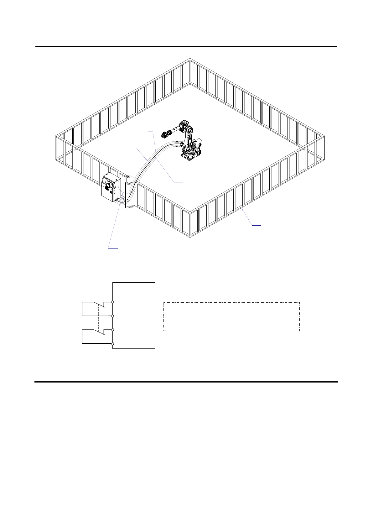
(3) Install a safety fence with a gate so that no working person can enter the work area without passing
through the gate. Install an interlocking device, a safety plug, and so forth in the safety gate so that
the robot is stopped as the safety gate is opened.
The controller is designed to receive this interlocking signal of the door switch. When the gate
is opened and this signal received, the controller stops the robot (Please refer to "STOP
TYPE OF ROBOT" in SAFETY PRECAUTIONS for detail of stop type). For connection, see
Fig.3 (b).
Provide the peripheral devices with appropriate grounding (Class A, Class B, Class C, and Class D).
(4)
s-2
Page 25

B-83525EN/01 SAFETY PRECAUTIONS
(5) Try to install the peripheral devices outside the work area.
(6) Draw an outline on the floor, clearly indicating the range of the robot motion, including the tools
such as a hand.
(7) Install a mat switch or photoelectric switch on the floor with an interlock to a visual or aural alarm
that stops the robot when a working person enters the work area.
(8) If necessary, install a safety lock so that no one except the working person in charge can turn on the
power of the robot.
The circuit breaker installed in the controller is designed to disable anyone from turning it on
when it is locked with a padlock.
(9) When adjusting each peripheral device independently, be sure to turn off the power of the robot
(10) Operators should be ungloved while manipulating the operator’s panel or teach pendant. Operation
with gloved fingers could cause an operation error.
(11) Programs, system variables, and other information can be saved on memory card or USB memories.
Be sure to save the data periodically in case the data is lost in an accident.
(12) The robot should be transported and installed by accurately following the procedures recommended
by FANUC. Wrong transportation or installation may cause the robot to fall, resulting in severe
injury to workers.
(13) In the first operation of the robot after installation, the operation should be restricted to low speeds.
Then, the speed should be gradually increased to check the operation of the robot.
(14) Before the robot is started, it should be checked that no one is in the area of the safety fence. At the
same time, a check must be made to ensure that there is no risk of hazardous situations. If detected,
such a situation should be eliminated before the operation.
(15) When the robot is used, the following precautions should be taken. Otherwise, the robot and
peripheral equipment can be adversely affected, or workers can be severely injured.
- Avoid using the robot in a flammable environment.
- Avoid using the robot in an explosive environment.
- Avoid using the robot in an environment full of radiation.
- Avoid using the robot under water or at high humidities.
- Avoid using the robot to carry a person or animal.
- Avoid using the robot as a stepladder. (Never climb up on or hang from the robot.)
(16) After connecting the safety signals like external emergency stop signal and/or safety fence signal,
verify that,
All safety signals stop the robot as intended.
There is no mistake in connection of safety signals.
s-3
Page 26
SAFETY PRECAUTIONS B-83525EN/01
p
Fig.3 (a) Safety fence and safety gate
F
ig.3 (b) Limit switch circuit diagram of the safety fence
(Note)
Connect EAS1 and EAS11, EAS2 and EAS21.
Terminals EAS1, EA11,EAS2,EAS21 are on the emergency sto
board.
3.1 OPERATOR SAFETY
The operator is a person who operates the robot system. In this sense, a worker who operates the teach
pendant is also an operator. However, this section does not apply to teach pendant operators.
(1) If you do not have to operate the robot, turn off the power of the robot controller or press the
EMERGENCY STOP button, and then proceed with necessary work.
(2) Operate the robot system at a location outside of the safety fence
(3) Install a safety fence with a safety gate to prevent any worker other than the operator from entering
the work area unexpectedly and to prevent the worker from entering a dangerous area.
(4) Install an EMERGENCY STOP button within the operator’s reach.
s-4
Page 27
B-83525EN/01 SAFETY PRECAUTIONS
y
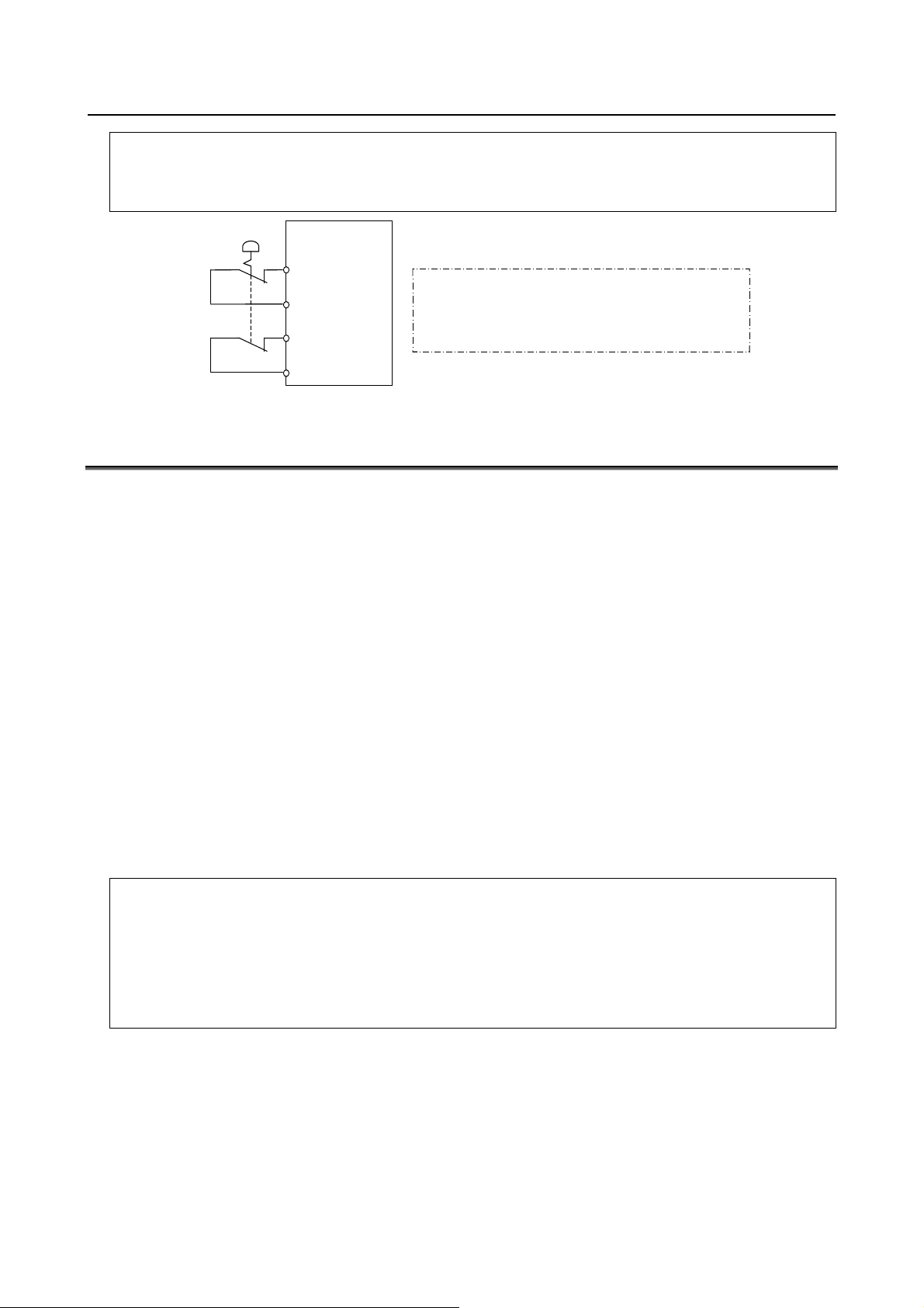
The robot controller is designed to be connected to an external EMERGENCY STOP button.
With this connection, the controller stops the robot operation (Please refer to "STOP TYPE
OF ROBOT" in SAFETY PRECAUTIONS for detail of stop type), when the external
EMERGENCY STOP button is pressed. For connection, see Fir.3.1.
Fig. 3.1 Connection Diagram for External Emergency Stop Button
(Note)
Connect EES1 and EES11, EES2 and EES21.
Terminals EES1,EES11,EES2,EES21 are on the emergenc
stop board.
3.2 SAFETY OF THE PROGRAMMER
While teaching the robot, the operator must enter the work area of the robot. The operator must ensure
the safety of the teach pendant operator especially.
(1) Unless it is specifically necessary to enter the robot work area, carry out all tasks outside the area.
(2) Before teaching the robot, check that the robot and its peripheral devices are all in the normal
operating condition.
(3) If it is inevitable to enter the robot work area to teach the robot, check the locations, settings, and
other conditions of the safety devices (such as the EMERGENCY STOP button, the DEADMAN
switch on the teach pendant) before entering the area.
(4) The programmer must be extremely careful not to let anyone else enter the robot work area.
(5) Programming should be done outside the area of the safety fence as far as possible. If programming
needs to be done in the area of the safety fence, the programmer should take the following
precautions:
- Before entering the area of the safety fence, ensure that there is no risk of dangerous situations in
the area.
- Be prepared to press the emergency stop button whenever necessary.
- Robot motions should be made at low speeds.
- Before starting programming, check the entire system status to ensure that no remote instruction to
the peripheral equipment or motion would be dangerous to the user.
The operator panel is provided with an emergency stop button and a key switch (mode switch) for selecting the
automatic operation mode (AUTO) and the teach modes (T1 and T2). Before entering the inside of the safety
fence for the purpose of teaching, set the switch to a teach mode, remove the key from the mode switch to prevent
other people from changing the operation mode carelessly, then open the safety gate. If the safety gate is opened
with the automatic operation mode set, the robot stops (Please refer to "STOP TYPE OF ROBOT" in SAFETY
PRECAUTIONS for detail of stop type). After the switch is set to a teach mode, the safety gate is disabled. The
programmer should understand that the safety gate is disabled and is responsible for keeping other people from
entering the inside of the safety fence.
s-5
Page 28
SAFETY PRECAUTIONS B-83525EN/01
The teach pendant is provided with an enable/disable switch, DEADMAN switch as well as an emergency stop
button. These button and switch function as follows:
(1) Emergency stop button: Causes an emergency stop (Please refer to "STOP TYPE OF ROBOT" in SAFETY
PRECAUTIONS for detail of stop type) when pressed.
(2) DEADMAN switch: Functions differently depending on the teach pendant enable/disable switch setting
status.
(a) Disable: The DEADMAN switch is disabled.
(b) Enable: Servo power is turned off when the operator releases the DEADMAN switch or when the
operator presses the switch strongly.
Note) The DEADMAN switch is provided to stop the robot when the operator releases the teach pendant or
presses the pendant strongly in case of emergency. The R-30iB Mate employs a 3-position
DEADMAN switch, which allows the robot to operate when the 3-position DEADMAN switch is pressed
to its intermediate point. When the operator releases the DEADMAN switch or presses the switch
strongly, the robot stops immediately.
Based on the risk assessment by FANUC, number of operation of DEADMAN SW should not exceed about 10000
times per year.
The operator’s intention of starting teaching is determined by the controller through the dual operation of setting the
teach pendant enable/disable switch to the enable position and pressing the DEADMAN switch. The operator
should make sure that the robot could operate in such conditions and be responsible in carrying out tasks safely.
The teach pendant, operator panel, and peripheral device interface send each robot start signal. However the
validity of each signal changes as follows depending on the mode switch of the operator panel, the teach pendant
enable/disable switch and the remote condition on the software.
Teach pendant
Mode
AUTO
mode
T1, T2
mode
T1,T2 mode: DEADMAN switch is effective.
enable/disable
switch
On
Off
On
Off
Software
remote
condition
Local Not allowed Not allowed Not allowed
Remote Not allowed Not allowed Not allowed
Local Not allowed Allowed to start Not allowed
Remote Not allowed Not allowed Allowed to start
Local Allowed to start Not allowed Not allowed
Remote Allowed to start Not allowed Not allowed
Local Not allowed Not allowed Not allowed
Remote Not allowed Not allowed Not allowed
Teach pendant Operator panel Peripheral device
(6) To start the system using the operator’s panel, make certain that nobody is the robot work area and
that there are no abnormal conditions in the robot work area.
(7) When a program is completed, be sure to carry out a test operation according to the procedure
below.
(a) Run the program for at least one operation cycle in the single step mode at low speed.
(b) Run the program for at least one operation cycle in the continuous operation mode at low
speed.
(c) Run the program for one operation cycle in the continuous operation mode at the intermediate
speed and check that no abnormalities occur due to a delay in timing.
(d) Run the program for one operation cycle in the continuous operation mode at the normal
operating speed and check that the system operates automatically without trouble.
(e) After checking the completeness of the program through the test operation above, execute it in
the automatic operation mode.
(8) While operating the system in the automatic operation mode, the teach pendant operator should
leave the robot work area.
s-6
Page 29

B-83525EN/01 SAFETY PRECAUTIONS
3.3 SAFETY OF THE MAINTENANCE ENGINEER
For the safety of maintenance engineer personnel, pay utmost attention to the following.
(1) During operation, never enter the robot work area.
(2) A hazardous situation may arise when the robot or the system, are kept with their power-on during
maintenance operations. Therefore, for any maintenance operation, the robot and the system should
be put into the power-off state. If necessary, a lock should be in place in order to prevent any other
person from turning on the robot and/or the system. In case maintenance needs to be executed in the
power-on state, the emergency stop button must be pressed.
(3) If it becomes necessary to enter the robot operation range while the power is on, press the
emergency stop button on the operator panel, or the teach pendant before entering the range. The
maintenance personnel must indicate that maintenance work is in progress and be careful not to
allow other people to operate the robot carelessly.
(4) When entering the area enclosed by the safety fence, the maintenance worker should check the entire
system to make sure that no dangerous situations are present. If the worker needs to enter the area of
the fence while a dangerous situation exists, the worker should always take extreme care and check
the current system status.
(5) Before the maintenance of the pneumatic system is started, the supply pressure should be shut off
and the pressure in the piping should be reduced to zero.
(6) Before the start of teaching, check that the robot and its peripheral devices are all in the normal
operating condition.
(7) Do not operate the robot in the automatic mode while anybody is in the robot work area.
(8) When you maintain the robot alongside a wall or instrument, or when multiple workers are working
nearby, make certain that their escape path is not obstructed.
(9) When a tool is mounted on the robot, or when any moving device other than the robot is installed,
such as belt conveyor, pay careful attention to its motion.
(10) If necessary, have a worker who is familiar with the robot system stand beside the operator panel
and observe the work being performed. If any danger arises, the worker should be ready to press
the EMERGENCY STOP button at any time.
(11) When replacing a part, please contact FANUC service center. If a wrong procedure is followed, an
accident may occur, causing damage to the robot and injury to the worker.
(12) When replacing or reinstalling components, take care to prevent foreign matter from entering the
system.
(13) When handling each unit or printed circuit board in the controller during inspection, turn off the
circuit breaker to protect against electric shock.
If there are two cabinets, turn off the both circuit breaker.
(14) A part should be replaced with a part recommended by FANUC. If other parts are used, malfunction
or damage would occur. Especially, a fuse that is not recommended by FANUC should not be used.
Such a fuse may cause a fire.
(15) When restarting the robot system after completing maintenance work, make sure in advance that
there is no person in the work area and that the robot and the peripheral devices are not abnormal.
(16) When a motor or brake is removed, the robot arm should be supported with a crane or other
equipment beforehand so that the arm would not fall during the removal.
(17) Whenever grease is spilled on the floor, it should be removed as quickly as possible to prevent
dangerous falls.
(18) The following parts are heated. If a maintenance worker needs to touch such a part in the heated
state, the worker should wear heat-resistant gloves or use other protective tools.
- Servo motor
- Inside the controller
(19) Maintenance should be done under suitable light. Care must be taken that the light would not cause
any danger.
s-7
Page 30

SAFETY PRECAUTIONS B-83525EN/01
(20) When a motor, decelerator, or other heavy load is handled, a crane or other equipment should be
used to protect maintenance workers from excessive load. Otherwise, the maintenance workers
would be severely injured.
(21) The robot should not be stepped on or climbed up during maintenance. If it is attempted, the robot
would be adversely affected. In addition, a misstep can cause injury to the worker.
(22) After the maintenance is completed, spilled oil or water and metal chips should be removed from the
floor around the robot and within the safety fence.
(23) When a part is replaced, all bolts and other related components should put back into their original
places. A careful check must be given to ensure that no components are missing or left unmounted.
(24) In case robot motion is required during maintenance, the following precautions should be taken :
- Foresee an escape route. And during the maintenance motion itself, monitor continuously the
whole system so that your escape route will not become blocked by the robot, or by peripheral
equipment.
- Always pay attention to potentially dangerous situations, and be prepared to press the emergency
stop button whenever necessary.
(25) The robot should be periodically inspected. (Refer to the manual of the controller or mechanical
unit.) A failure to do the periodical inspection can adversely affect the performance or service life of
the robot and also may cause an accident.
(26) After a part is replaced, a test operation should be given for the robot according to a predetermined
method. (See TESTING section of “Controller operator’s manual”.) During the test operation, the
maintenance staff should work outside the safety fence.
4 SAFETY OF THE TOOLS AND
PERIPHERAL DEVICES
4.1 PRECAUTIONS IN PROGRAMMING
(1) Use a limit switch or other sensor to detect a dangerous condition and, if necessary, design the
program to stop the robot when the sensor signal is received.
(2) Design the program to stop the robot when an abnormal condition occurs in any other robots or
peripheral devices, even though the robot itself is normal.
(3) For a system in which the robot and its peripheral devices are in synchronous motion, particular care
must be taken in programming so that they do not interfere with each other.
(4) Provide a suitable interface between the robot and its peripheral devices so that the robot can detect
the states of all devices in the system and can be stopped according to the states.
4.2 PRECAUTIONS FOR MECHANISM
(1) Keep the component cells of the robot system clean, and operate the robot in an environment free of
grease, water, and dust.
(2) Don’t use unconfirmed liquid for cutting fluid and cleaning fluid.
(3) Employ a limit switch or mechanical stopper to limit the robot motion so that the robot or cable does
not strike against its peripheral devices or tools.
(4) Observe the following precautions about the mechanical unit cables. When theses attentions are not
kept, unexpected troubles might occur.
• Use mechanical unit cable that have required user interface.
• Don’t add user cable or hose to inside of mechanical unit.
• Please do not obstruct the movement of the mechanical unit cable when cables are added to
outside of mechanical unit.
s-8
Page 31

B-83525EN/01 SAFETY PRECAUTIONS
• In the case of the model that a cable is exposed, Please do not perform remodeling (Adding a
protective cover and fix an outside cable more) obstructing the behavior of the outcrop of the
cable.
• Please do not interfere with the other parts of mechanical unit when install equipments in the
robot.
(5) The frequent power-off stop for the robot during operation causes the trouble of the robot. Please
avoid the system construction that power-off stop would be operated routinely. (Refer to bad case
example.) Please execute power-off stop after reducing the speed of the robot and stopping it by
hold stop or cycle stop when it is not urgent. (Please refer to "STOP TYPE OF ROBOT" in
SAFETY PRECAUTIONS for detail of stop type.)
(Bad case example)
• Whenever poor product is generated, a line stops by emergency stop.
• When alteration was necessary, safety switch is operated by opening safety fence and
power-off stop is executed for the robot during operation.
• An operator pushes the emergency stop button frequently, and a line stops.
• An area sensor or a mat switch connected to safety signal operate routinely and power-off stop
is executed for the robot.
(6) Robot stops urgently when collision detection alarm (SRVO-050) etc. occurs. The frequent urgent
stop by alarm causes the trouble of the robot, too. So remove the causes of the alarm.
5 SAFETY OF THE ROBOT MECHANISM
5.1 PRECAUTIONS IN OPERATION
(1) When operating the robot in the jog mode, set it at an appropriate speed so that the operator can
manage the robot in any eventuality.
(2) Before pressing the jog key, be sure you know in advance what motion the robot will perform in the
jog mode.
5.2 PRECAUTIONS IN PROGRAMMING
(1) When the work areas of robots overlap, make certain that the motions of the robots do not interfere
with each other.
(2) Be sure to specify the predetermined work origin in a motion program for the robot and program the
motion so that it starts from the origin and terminates at the origin.
Make it possible for the operator to easily distinguish at a glance that the robot motion has
terminated.
5.3 PRECAUTIONS FOR MECHANISMS
(1) Keep the work areas of the robot clean, and operate the robot in an environment free of grease, water,
and dust.
5.4 PROCEDURE TO MOVE ARM WITHOUT DRIVE POWER
IN EMERGENCY OR ABNORMAL SITUATIONS
For emergency or abnormal situations
used to move the robot axes without drive power.
Please refer to this manual and mechanical unit operator’s manual for using method of brake release unit
and method of supporting robot.
(e.g. persons trapped in or by the robot), brake release unit can be
s-9
Page 32

SAFETY PRECAUTIONS B-83525EN/01
6 SAFETY OF THE END EFFECTOR
6.1 PRECAUTIONS IN PROGRAMMING
(1) To control the pneumatic, hydraulic and electric actuators, carefully consider the necessary time
delay after issuing each control command up to actual motion and ensure safe control.
(2) Provide the end effector with a limit switch, and control the robot system by monitoring the state of
the end effector.
7 STOP TYPE OF ROBOT
The following three robot stop types exist:
Power-Off Stop (Category 0 following IEC 60204-1)
Servo power is turned off and the robot stops immediately. Servo power is turned off when the robot is
moving, and the motion path of the deceleration is uncontrolled.
The following processing is performed at Power-Off stop.
- An alarm is generated and servo power is turned off.
- The robot operation is stopped immediately. Execution of the program is paused.
Controlled stop (Category 1 following IEC 60204-1)
The robot is decelerated until it stops, and servo power is turned off.
The following processing is performed at Controlled stop.
- The alarm "SRVO-199 Controlled stop" occurs along with a decelerated stop. Execution of the
program is paused.
- An alarm is generated and servo power is turned off.
Hold (Category 2 following IEC 60204-1)
The robot is decelerated until it stops, and servo power remains on.
The following processing is performed at Hold.
- The robot operation is decelerated until it stops. Execution of the program is paused.
WARNING
The stopping distance and stopping time of Controlled stop are longer than the
stopping distance and stopping time of Power-Off stop. A risk assessment for
the whole robot system, which takes into consideration the increased stopping
distance and stopping time, is necessary when Controlled stop is used.
When the E-Stop button is pressed or the FENCE is open, the stop type of robot is Power-Off stop or
Controlled stop. The configuration of stop type for each situation is called stop pattern. The stop pattern
is different according to the controller type or option configuration.
s-10
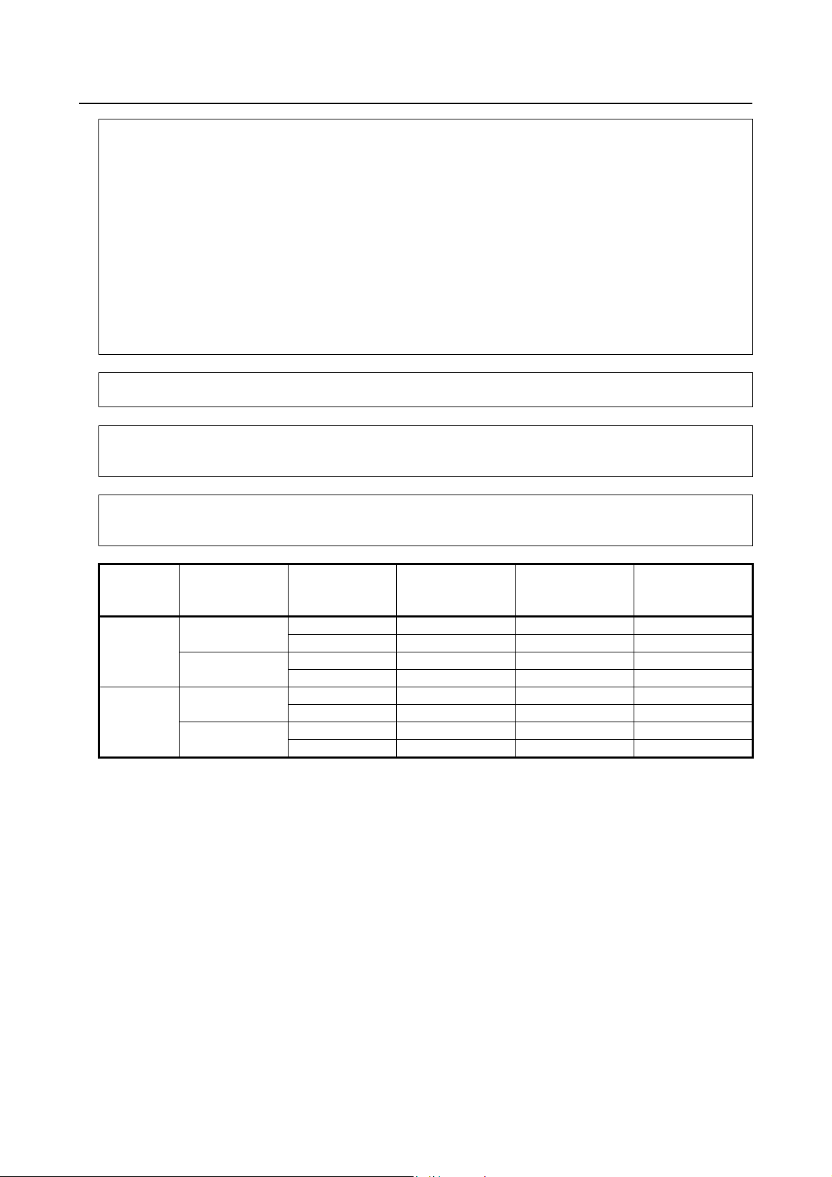
Page 33

B-83525EN/01 SAFETY PRECAUTIONS
There are the following 2 Stop patterns.
Stop
pattern
A
C
Mode
AUTO P-Stop P-Stop C-Stop C-Stop
T1 P-Stop P-Stop - C-Stop
T2 P-Stop P-Stop - C-Stop
AUTO C-Stop C-Stop C-Stop C-Stop
T1 P-Stop P-Stop - C-Stop
T2 P-Stop P-Stop - C-Stop
E-Stop
button
External E-Stop FENCE open SVOFF input
P-Stop: Power-Off stop
C-Stop: Controlled stop
-: Disable
WARNING
In this manual, the term “Emergency-stop” is used for the stop by above safety
signals. Please refer to above table for actual stop type.
The following table indicates the Stop pattern according to the controller type or option configuration.
Option Stop pattern
Standard A
Controlled stop by E-Stop
(A05B-2600-J570)
C
The stop pattern of the controller is displayed in "Stop pattern" line in software version screen. Please
refer "Software version" in operator's manual of controller for the detail of software version screen.
"Controlled stop by E-Stop" option
"Controlled stop by E-Stop" option (A05B-2600-J570) is an optional function. When this option is
loaded, the stop type of the following alarms becomes Controlled stop but only in AUTO mode. In T1
or T2 mode, the stop type is Power-Off stop which is the normal operation of the system.
Alarm Condition
SRVO-001 Operator panel E-stop Operator panel E-stop is pressed.
SRVO-002 Teach pendant E-stop Teach pendant E-stop is pressed.
SRVO-007 External emergency stops External emergency stop input (EES1-EES11, EES2-EES21) is
open.
SRVO-408 DCS SSO Ext Emergency Stop In DCS Safe I/O connect function, SSO[3] is OFF.
SRVO-409 DCS SSO Servo Disconnect In DCS Safe I/O connect function, SSO[4] is OFF.
Controlled stop is different from Power-Off stop as follows:
- In Controlled stop, the robot is stopped on the program path. This function is effective for a system
where the robot can interfere with other devices if it deviates from the program path.
- In Controlled stop, physical impact is less than Power-Off stop. This function is effective for
systems where the physical impact to the mechanical unit or EOAT (End Of Arm Tool) should be
minimized.
- The stopping distance and stopping time of Controlled stop is longer than the stopping distance and
stopping time of Power-Off stop, depending on the robot model and axis. Please refer the operator's
manual of a particular robot model for the data of stopping distance and stopping time.
When this option is loaded, this function can not be disabled.
The stop type of DCS Position and Speed Check functions is not affected by the loading of this option.
s-11
Page 34

SAFETY PRECAUTIONS B-83525EN/01
WARNING
The stopping distance and stopping time of Controlled stop are longer than the
stopping distance and stopping time of Power-Off stop. A risk assessment for
the whole robot system, which takes into consideration the increased stopping
distance and stopping time, is necessary when this option is loaded.
8 WARNING LABEL
(1) Step-on prohibitive label
Fig.8 (a) Step-on prohibitive label
Description
Do not step on or climb the robot or controller as it may adversely affect the robot or controller
and you may get hurt if you lose your footing.
(2) High-temperature warning label
Fig.8 (b) High-Temperature warning label
Description
Be cautious about a section where this label is affixed, as the section generates heat. If you
must touch such a section when it is hot, use a protective provision such as heat-resistant
gloves.
s-12
Page 35

B-83525EN/01 SAFETY PRECAUTIONS
(3) High-voltage warning label
Fig.8 (c) High-voltage warning label
Description
A high voltage is applied to the places where this label is attached.
Before starting maintenance, turn the power to the controller off, and turn the circuit breaker
off to avoid electric shock hazards. Take additional precautions with the servo amplifier and
other equipment, because high-voltage remains in these units for a certain amounts of time
s-13
Page 36

Page 37

B-83525EN/01 PREFACE
PREFACE
This manual describes the following models (R-30iB Mate controller).
Model Abbreviation
FANUC Robot LR Mate 200iD LR Mate 200iD LR Mate 200iD
p-1
Page 38

Page 39

B-83525EN/01 TABLE OF CONTENTS
TABLE OF CONTENTS
SAFETY PRECAUTIONS............................................................................s-1
PREFACE....................................................................................................p-1
1 OVERVIEW .............................................................................................3
2 CONFIGURATION ..................................................................................4
2.1 EXTERNAL VIEW OF THE CONTROLLER .................................................. 4
2.2 COMPONENT FUNCTIONS.......................................................................... 8
2.3 PREVENTIVE MAINTENANCE ..................................................................... 9
3 TROUBLESHOOTING .......................................................................... 11
3.1 POWER CANNOT BE TURNED ON ........................................................... 11
3.1.1 When the Teach Pendant Cannot be Powered on...................................................11
3.1.2 When the Teach Pendant Does not Change from the Initial Screen.......................12
3.2 ALARM OCCURRENCE SCREEN.............................................................. 13
3.3 STOP SIGNALS .......................................................................................... 16
3.4 MASTERING ............................................................................................... 17
3.5 TROUBLESHOOTING USING THE ERROR CODE ................................... 19
3.6 FUSE-BASED TROUBLESHOOTING......................................................... 68
3.7 TROUBLESHOOTING BASED ON LED INDICATIONS .............................72
3.7.1 Troubleshooting Using the LEDS On the Main Board ..........................................73
3.7.2 Troubleshooting by LEDs on the 6-Axis Servo Amplifier ....................................76
3.7.3 Troubleshooting by LED on the Emergency Stop Board.......................................78
3.7.4 Troubleshooting by Alarm LEDs on the Process I/O Board ..................................80
3.8 MANUAL OPERATION IMPOSSIBLE ......................................................... 81
3.9 LEDS ON UNITS SUPPORTING I/O LINK i ...................................................... 82
3.9.1 Meanings of LEDs on Units Supporting I/O Link i ...............................................82
4 PRINTED CIRCUIT BOARDS............................................................... 84
4.1 MAIN BOARD.............................................................................................. 85
4.2 EMERGENCY STOP BOARD:A20B-2005-0150 .........................................87
4.3 BACKPLANE ...............................................................................................87
4.4 PROCESS I/O BOARD MA (A20B-2004-0381)........................................... 88
4.5 PROCESS I/O BOARD MB (A20B-2101-0731)........................................... 89
4.6 I/O CONNECTOR CONVERTER BOARD (A20B-2004-0411) ....................90
5 SERVO AMPLIFIERS ........................................................................... 91
5.1 LEDS OF SERVO AMPLIFIER.................................................................... 92
5.2 SETTING OF SERVO AMPLIFIER.............................................................. 93
5.3 6-AXIS SERVO AMPLIFIER SPECIFICATIONS .........................................94
6 POWER SUPPLY..................................................................................95
6.1 BLOCK DIAGRAM OF THE POWER SUPPLY ...........................................95
7 REPLACING UNITS..............................................................................96
c - 1
Page 40

TABLE OF CONTENTS B-83525EN/01
7.1 REPLACING THE PRINTED-CIRCUIT BOARDS .......................................96
7.1.1 Replacing the Backplane Board (Unit)...................................................................97
7.1.2 Replacing the Main Board......................................................................................98
7.2 REPLACING CARDS AND MODULES ON THE MAIN BOARD .................99
7.3 REPLACING THE E-STOP UNIT ..............................................................104
7.4 REPLACING THE EMERGENCY STOP BOARD .....................................105
7.5 REPLACING THE POWER SUPPLY UNIT............................................... 106
7.6 REPLACING THE REGENERATIVE RESISTOR UNIT ............................ 107
7.7 REPLACING THE 6-AXIS SERVO AMPLIFIER ........................................108
7.8 REPLACING THE TEACH PENDANT....................................................... 110
7.9 REPLACING THE CONTROL SECTION FAN MOTOR ............................ 111
7.10 REPLACING THE AC FAN MOTOR ......................................................... 112
7.10.1 Replacing the Heat Exchanger and Door Fan Unit (A-cabinet) ...........................112
7.11 REPLACING THE BATTERY .................................................................... 113
7.11.1 Battery for Memory Backup (3 VDC)..................................................................113
1 GENERAL ...........................................................................................117
2 BLOCK DIAGRAM..............................................................................118
3 ELECTRICAL CONNECTIONS...........................................................119
3.1 CONNECTION DIAGRAM BETWEEN MECHANICAL UNITS ..................119
3.2 FANUC I/O LINK........................................................................................ 121
3.2.1 Connection of I/O Link ........................................................................................121
3.2.2 Connection of the I/O Link Cable ........................................................................122
3.3 EXTERNAL CABLE WIRING DIAGRAM ................................................... 125
3.3.1 Robot Connection Cables.....................................................................................125
3.3.2 Teach Pendant Cable ............................................................................................127
3.3.3 Connecting the Input Power .................................................................................128
3.3.3.1 Connecting the input power cable ................................................................... 128
3.3.3.2 Leakage breaker............................................................................................... 129
3.3.4 Connecting the External Emergency Stop............................................................129
3.3.5 Connecting the Auxiliary Axis Brake (CRR65 A/B) ...........................................136
3.3.6 Connecting the Auxiliary Axis Over Travel (CRM68)........................................137
4 PERIPHERAL DEVICE, ARC WELDING, AND EE INTERFACES ....138
4.1 PERIPHERAL DEVICE INTERFACE BLOCK DIAGRAM.......................... 140
4.1.1 In Case of Main Board (CRMA15, CRMA16) ....................................................140
4.1.2 In the Case of the Process I/O Board MA ............................................................140
4.1.3 In the Case of the Process I/O Board MB ............................................................141
4.1.4 In the Case of the Connector Conversion Board ..................................................142
4.2 I/O SIGNALS OF MAIN BOARD................................................................ 143
4.3 INTERFACE FOR PERIPHERAL DEVICES.............................................. 145
4.3.1 Connection between the Main Board (CRMA15, CRMA16) and
Peripheral Devices................................................................................................145
4.3.2 Connection between the Connector Conversion Board and Peripheral Devices..151
4.3.3 Connection between the Process I/O Board MA and Peripheral Devices............152
4.4 INTERFACE FOR WELDING MACHINES ................................................ 156
4.4.1 Connection between the Process I/O Board MB and Welding Machines ............156
c - 2
Page 41

B-83525EN/01 TABLE OF CONTENTS
4.5 INTERFACE FOR END EFFECTOR ......................................................... 158
4.5.1 Connection between the LR Mate 200iD and End Effector.................................158
4.6 DIGITAL I/O SIGNAL SPECIFICATIONS .................................................. 159
4.6.1 Peripheral Device Interface A ..............................................................................159
4.6.2 EE Interface..........................................................................................................162
4.6.3 I/O Signal Specifications for ARC-Welding Interface
(A-cabinet/Process I/O Board MB) .....................................................................163
4.7 SPECIFICATIONS OF THE CABLES USED FOR PERIPHERAL DEVICES
AND WELDERS ........................................................................................166
4.7.1 Peripheral Device Interface A1 Cable
(CRMA15: Tyco Electronics AMP, 40 pins) .......................................................166
4.7.2 Peripheral Device Interface A2 Cable
(CRMA16: Tyco Electronics AMP, 40 pins) .......................................................166
4.7.3 Peripheral Device Interface B1 and B2 Cables
(CRMA52; Tyco Electronics AMP, 30 pin).........................................................167
4.7.4 ARC Weld Connection Cables
(CRW11; Tyco Electronics AMP, 20 pin) ...........................................................167
4.8 CABLE CONNECTION FOR THE PERIPHERAL DEVICES, END
EFFECTORS, AND ARC WELDERS ........................................................ 168
4.8.1 Peripheral Device Connection Cable....................................................................168
4.8.2 Peripheral Device Cable Connector .....................................................................169
4.8.3 Recommended Cables ..........................................................................................172
4.9 CONNECTION OF HDI .............................................................................173
4.9.1 Connecting HDI ...................................................................................................173
4.9.2 Input Signal Rules for the High-speed Skip (HDI) ..............................................174
4.10 CONNECTING THE COMMUNICATION UNIT ......................................... 175
4.10.1 RS-232-C Interface...............................................................................................175
4.10.1.1 Interface ........................................................................................................... 175
4.10.1.2 RS-232-C interface signals .............................................................................. 176
4.10.1.3 Connection between RS-232-C interface and I/O device ................................ 176
4.10.2 Ethernet Interface .................................................................................................178
4.10.2.1 Connection to Ethernet .................................................................................... 178
4.10.2.2 Routing of the Ethernet Cable ......................................................................... 179
4.10.2.3 100BASE-TX Connector (CD38A, CD38B) Pin Assignments....................... 179
4.10.2.4 Twisted-pair Cable Specification..................................................................... 180
4.10.2.5 Electrical Noise Countermeasures ................................................................... 183
4.10.2.6 Check Items at Installation .............................................................................. 186
5 TRANSPORTATION AND INSTALLATION .......................................187
5.1 TRANSPORTATION.................................................................................. 187
5.2 INSTALLATION .........................................................................................188
5.2.1 Installation Method...............................................................................................188
5.2.2 Assemble at Installation .......................................................................................189
5.3 INSTALLATION OF TEACH PENDANT HOOK (Option)........................... 190
5.4 INSTALLATION CONDITION .................................................................... 191
5.5 ADJUSTMENT AND CHECKS AT INSTALLATION .................................. 193
5.6 RESETTING OVERTRAVEL AND EMERGENCY STOP
AT INSTALLATION.................................................................................... 193
5.6.1 Peripheral Device Interface Processing................................................................193
5.6.2 Resetting Overtravel.............................................................................................194
5.6.3 How to Disable/Enable HBK ...............................................................................194
5.6.4 How to Disable/Enable Pneumatic Pressure Alarm (PPABN).............................194
c - 3
Page 42

TABLE OF CONTENTS B-83525EN/01
A TOTAL CONNECTION DIAGRAM...................................................... 197
B SPECIFICATIONS OF PERIPHERAL DEVICE INTERFACE.............213
B.1 SIGNAL ..................................................................................................... 213
B.2 SETTING COMMON VOLTAGE................................................................ 215
B.3 I/O SIGNALS ............................................................................................. 215
B.3.1 Input Signals.........................................................................................................215
B.3.2 Output Signals ......................................................................................................218
B.4 SPECIFICATIONS OF DIGITAL INPUT/OUTPUT..................................... 221
B.4.1 Overview ..............................................................................................................221
B.4.2 Input/Output Hardware Usable in the R-30iB Mate Controller ...........................221
B.4.3 Software Specifications ........................................................................................222
C OPTICAL FIBER CABLE....................................................................223
D BRAKE RELEASE UNIT.....................................................................226
D.1 SAFETY PRECAUTIONS.......................................................................... 226
D.2 CONFIRMATIONS BEFORE OPERATION............................................... 226
D.3 OPERATION.............................................................................................. 227
D.3.1 In case of operating to the robot ...........................................................................227
D.3.2 In case of operating to the auxiliary Axis.............................................................229
D.4 HOW TO CONNECT THE PLUG TO THE POWER CABLE (IN CASE OF NO
POWER PLUG) .........................................................................................230
D.5 DIMENSION .............................................................................................. 231
D.6 FUSE ......................................................................................................... 232
D.7 SPECIFICATIONS..................................................................................... 233
E TEACH PENDANT DISCONNECT FUNCTION (Option) ...................234
E.1 CONFIGURATION..................................................................................... 234
E.2 PROCEDURE OF TEACH PENDANT DISCONNECT .............................. 234
E.2.1 Teach Pendant Disconnect ...................................................................................234
E.2.2 Teach Pendant Connect ........................................................................................235
F INSTRUCTION FOR TERMINAL BLOCK ..........................................236
c - 4
Page 43

I. MAINTENANCE
Page 44

Page 45

B-83525EN/01 MAINTENANCE 1.OVERVIEW
1 OVERVIEW
This manual is applied to R-30iB Mate controller (called R-30iB Mate).
R-30iB Mate has three variations depending on the required standards.
Basic controller: To meet Safety Standard and General electrical requirement
CE controller: To meet Machinery Directive, Low voltage Directive, EMC Directive to cover
the requirement of CE mark
NRTL controller: To meet UL/CSA standard
This manual covers these three variations of R-30iB Mate.
The difference of NRTL and CE controller from Basic controller is small as shown in Table 1 (ex. EMC
parts, Breakers).
And the specific descriptions of CE and NRTL controller have notifications in this manual.
Table 1. Applied standards
Basic
controller
CE
controller
NRTL
controller
Common
Standard
ISO 10218-1
ISO 13849-1
IEC 60204-1
IEC 61508
This manual describes the maintenance and connection of R-30iB Mate.
Maintenance Part: Troubleshooting, and the setting, adjustment, and replacement of units
Connection Part: Connection of R-30iB Mate to the robot mechanical unit and peripheral devices,
and installation of the controller
WARNING
Before you enter the robot working area, be sure to turn off the power to the
controller or press the EMERGENCY STOP button on the operator's panel or
teach pendant.
Otherwise, you could injure personnel or damage equipment.
EMC
Standard
- -
EN 55011
EN 61000-6-2
EN 61000-6-4
-
UL/CSA
Standard
-
UL1740
CAN/CSA Z434
NFPA79
Requirement Difference
Safety Standard
General electrical
requirement
CE Marking
•Europe
UL standard
CSA standard
•USA and Canada
•Noise filter
•EMC Cabinet
•Shielded cable
•UL listed main breaker
-
- 3 -
Page 46

Page 47

2.CONFIGURATION MAINTENANCE B-83525EN/01
2 CONFIGURATION
2.1 EXTERNAL VIEW OF THE CONTROLLER
The appearance and components might slightly differ depending on the controlled robot, application, and
options used.
Fig.2.1 (a) shows the view of R-30iB Mate.
Fig.2.1 (b) to (d) show the construction of the R-30iB Mate controller.
Fig.2.1 (e) to (g) show the external view of the operator’s panel and teach pendant.
Teach pendant hook
(Option)
Operator’s panel
Breaker
Teach pendant
(iPendant)
Fig.2.1 (a) External view of the R-30iB Mate controller
- 4 -
USB port (Option)
Page 48

B-83525EN/01 MAINTENANCE 2.CONFIGURATION
Emergency stop button
Main board
Battery
Back plane unit
mode switch
Heat exchanger 6-Axis Servo amplifier
Fig.2.1 (b) R-30iB Mate cabinet interior (Front-1)
Noise Filter
(EMC Option)
Breaker
E-stop unit
Fig.2.1 (c) R-30iB Mate cabinet interior (Front-2)
Power supply unit
Process I/O board
(Option)
- 5 -
Page 49

2.CONFIGURATION MAINTENANCE B-83525EN/01
Regenerative resistor
6-Axis Servo amplifier (Rear side)
Fig.2.1 (d) R-30iB Mate cabinet interior (Rear)
Mode switch
(In case of 3-mode switch)
CYCLE START button with LED(Green)
Fig.2.1 (e) R-30iB Mate operator’s panel
2 mode switch 3 mode switch
Fig.2.1 (f) Mode switch
Emergency Stop button
- 6 -
Page 50

B-83525EN/01 MAINTENANCE 2.CONFIGURATION
Enable/disable switch
Emergency Stop button
USB port
Fig.2.1 (g) Teach pendant (iPendant)
Deadman switch
- 7 -
Page 51

2.CONFIGURATION MAINTENANCE B-83525EN/01
2.2 COMPONENT FUNCTIONS
F
ig.2.2 Block diagram of the R-30iB Mate
- 8 -
Page 52

B-83525EN/01 MAINTENANCE 2.CONFIGURATION
- Main board
The main board contains a microprocessor, its peripheral circuits, memory, and operator's panel
control circuit. The main CPU controls servo mechanism positioning.
- I/O printed circuit board
Various types of printed circuit boards are provided for applications including process I/O board.
These are connected with FANUC I/O Link.
- E-stop unit
This unit controls the emergency stop system of the robot controller. It also has user interface
terminals of safety relevant signals, external on/off signals etc.
- Power supply unit
The power supply unit converts the AC power to various levels of DC power.
- Backplane printed circuit board
The various control printed circuit boards are mounted on the backplane printed circuit board.
- Teach pendant
All operations including robot programming are performed with this unit. The controller status and
data are indicated on the liquid-crystal display (LCD) on the pendant.
- 6-Axis Servo amplifier
The servo amplifier controls servomotor, Pulsecoder signal, brake control, overtravel and hand
broken.
- Operator's panel
Buttons and LEDs on the operator's panel are used to start the robot and to indicate the robot status.
- Fan unit, heat exchanger
These components cool the inside of the controller.
- Circuit breaker
If the electric system in the controller malfunctions, or if abnormal input power causes high current
in the system, the input power is connected to the circuit breaker to protect the equipment.
- Regenerative resistor
To discharge the counter electromotive force from the servomotor, connect a regenerative resistor to
the servo amplifier.
2.3 PREVENTIVE MAINTENANCE
Daily maintenance and periodic maintenance/inspection ensure reliable robot performance for extended
periods of time.
(1) Daily maintenance
Before operating the system each day, clean each part of the system and check the system parts for
any damage or cracks. Also, check the following:
(a) Before operation
Check the cable connected to the teach pendant for excessive twisting. Check the controller
and peripheral devices for abnormalities.
(b) After operation
At the end of operation, return the robot to the specified position, and then turn off the
controller. Clean each part, and check for any damage or cracks. If the ventilation port of
the controller is dusty, clean it.
(2) Check after one month
Check that the fan is rotating normally. If the fan has dirt and dust built up, clean the fan according
to step (d) described below for inspection to be performed every 6 months.
(3) Battery daily check
Replace the battery on the front panel of the main board every 4 years. Please refer to the Section
7.11.
(4) Maintenance tools
The following maintenance tools are recommended:
(a) Measuring instruments
- 9 -
Page 53

2.CONFIGURATION MAINTENANCE B-83525EN/01
AC/DC voltmeter (A digital voltmeter is sometimes required.)
Oscilloscope with a frequency range of 5 MHz or higher, two channels
(b) Tools
Phillips screwdrivers: Large, medium, and small
Standard screwdrivers: Large, medium, and small
Nut driver set (Metric)
Pliers
Needle-nose pliers
Diagonal cutting pliers
- 10 -
Page 54

Page 55

B-83525EN/01 MAINTENANCE 3.TROUBLESHOOTING
3 TROUBLESHOOTING
This chapter describes the checking method and corrective action for each error code indicated if a
hardware alarm occurs. Refer to the operator's manual to release program alarms.
3.1 POWER CANNOT BE TURNED ON
Check and Corrective action Figure
(Check 1) Check that the circuit
breaker is on and has not
tripped.
(Corrective
action)
a) If circuit breaker is OFF.
Turn on the circuit
breaker.
b) If the circuit breaker has
tripped, find the cause
by referencing the total
connection diagram
presented in the
appendix.
3.1.1 When the Teach Pendant Cannot be Powered on
Inspection and action Illustration
(Inspection 1) Confirm that fuse (FUSE3) on the
emergency stop board is not
blown. When it is blown, the
LED on the emergency stop board
lights in red. When fuse
(FUSE3) is blown, carry out action
1 and replace the fuse.
(Inspection 2) When fuse (FUSE3) is not blown,
carry out action 2.
(Action 1) (a) Check the cable of the teach
pendant for failure and replace it as
necessary.
(b) Check the teach pendant for
failure and replace it as necessary.
(c) Replace the emergency stop
board.
(Action 2) When the LED on the main board
does not light, replace the
emergency stop unit. When the
LED on the main board lights, carry
out action 1.
FUSE3
LED
(Red)
- 11 -
Page 56

3.TROUBLESHOOTING MAINTENANCE B-83525EN/01
3.1.2 When the Teach Pendant Does not Change from the Initial
Screen
Inspection and action Illustration
(Inspection 1)
Check that the status display LED and
7-segment LED on the main board
operate normally.
(Action) Carry out an action according to the
LED status. For details, see
"TROUBLESHOOTING USING THE
LEDS ON THE MAIN BOARD".
7 Segment LED
(Inspection 2)
When the LED on the main board
does not light in inspection 1, check
if fuse (FUSE1) on the main board is
blown.
(a) When fuse (FUSE1) is blown
See action 1.
(b) When fuse (FUSE1) is not blown
See action 2.
(Action 1) (a) Replace the backplane board.
(b) Replace the main board.
(c) When an option board is installed
in the mini slot, replace the option
board.
(Action 2) (a) Replace the emergency stop
unit.
(b) Replace the cable between the
main board and the emergency stop
unit.
(c) Replace the boards indicated in
action 1.
Back plane
RLED1
LEDG1
LEDG2
LEDG3
LEDG4
(Red)
(Green)
FUSE1
Mini slot (2slot)
- 12 -
Page 57

B-83525EN/01 MAINTENANCE 3.TROUBLESHOOTING
A
A
A
A
6
d
M
A
3.2 ALARM OCCURRENCE SCREEN
The alarm occurrence screen displays only the alarm conditions that are currently active. If an alarm reset
signal is input to reset the alarm conditions, the alarm occurrence screen displays the message "PAUSE or
more serious alarm has not occurred."
The alarm occurrence screen displays only the alarm conditions (if any) that occur after the most recently
entered alarm reset signal. To erase all alarm displays from the alarm occurrence screen. Press the
CLEAR key (+ shift) on the alarm history screen.
The alarm occurrence screen is intended to display PAUSE or alarms that are more serious. It will not
display WARN, NONE, or a reset. It is possible to disable PAUSE and some of more serious alarms from
being displayed by setting the $ER_NOHIS system variable appropriately.
If two or more alarms have occurred, the display begins with the most recent alarm.
Up to 100 lines can be displayed.
If an alarm has a cause code, it is displayed below the line indicating the alarm.
Pr
Press the screen
selection key to select
[4 ALARM].
ess the alarm key.
utomatic alarm display
u
pon occurrence
larm occurrence screen display
Pre
Press F3 [ACTIVE].
larm history screen display
Fig.3.2 Alarm occurrence screen and alarm history screen display procedure
ss F3 [HIST].
Displaying the alarm history/alarm detail information
Step
(1) Press the MENUS key to display the screen menu.
(2) Select [ALARM].
You will see a screen similar to the following.
If an alarm has occurred, however, the alarm screen appears automatically.
larm : Active
1/2
1 INTP-224 (TEST1, 6) Jump label faile
MEMO-027 Specified line does not exi
[ TYPE ] [ VIEW ] HIST RES_1CH
INTP-224 (TEST1,
EMO-027 Specified line does not exis JOINT
)Jump label faile
- 13 -
30%
larm detail code
Page 58

3.TROUBLESHOOTING MAINTENANCE B-83525EN/01
(3) To display the alarm history screen, press F3, [HIST].
Press F3 [ACTIVE] again, the alarm screen appears.
Alarm : Hist
1/25
1 INTP-224 (TEST1, 6) Jump label faile
2 R E S E T
3 SRVO-007 External emergency stop
4 SRVO-001 Operator panel E-stop
5 R E S E T
6 SRVO-001 Operator panel E-stop
7 SRVO-012 Power failure recovery
8 INTP-127 Power fail detected
9 SRVO-047 LVAL alarm (Group:1 Axis:5)
10 SRVO-047 LVAL alarm (Group:1 Axis:4)
11 SRVO-002 Teach pendant E-stop
[ TYPE ] [ VIEW ] ACTIVE CLEAR DETAIL
NOTE
The latest alarm is assigned number 1. To view messages that are currently
not on the screen, press the F5, HELP, and then press the right arrow key.
(4) To display the alarm detail screen, press F5, [HELP].
Alarm : Hist
DETAIL Alarm
INTP-224 (TEST1, 6) Jump label failed
MEMO-027 Specified line does not exist
STOP.L 21-NOV-11 12:16
Alarm : Hist
1 INTP-224 (TEST1, 6) Jump label faile
2 R E S E T
3 SRVO-007 External emergency stop
4 SRVO-001 Operator panel E-stop
5 R E S E T
6 SRVO-001 Operator panel E-stop
7 SRVO-012 Power failure recovery
[ TYPE ] [ VIEW ] ACTIVE CLEAR DETAIL
(5) To return to the alarm history screen, press the PREV key.
(6) To delete all the alarm histories, press and hold down the SHIFT key, then press F4, [CLEAR].
NOTE
When system variable $ER_NOHIS = 1, NONE alarms or WARN alarms are not
recorded. When $ER_NOHIS=2, resets are not recorded in the alarm history.
When $ER_NOHIS=3, resets, WARN alarms, and NONE alarms are not
recorded.
- 14 -
Page 59

B-83525EN/01 MAINTENANCE 3.TROUBLESHOOTING
The following map indicates teach pendant operations used to check an alarm.
4 ALARM
F1 [TYPE]
Alarm : Active
F1 [TYPE]
F3 HIST
Alarm : HIST
F1 [TYPE]
F3 [ACTIVE]
F4 CLEAR
F5 HELP
DETAIL Alarm
F1 [TYPE]
F3 [ACTIVE]
F4 CLEAR
F5 HELP
- 15 -
Page 60

3.TROUBLESHOOTING MAINTENANCE B-83525EN/01
3.3 STOP SIGNALS
The stop signal screen indicates the state of signals related to stop.
To be specific, the screen indicates whether each stop signal is currently on. On this screen, it is
impossible to change the state of any stop signal.
Table 3.3 Stop signals
Stop signal Description
Operator’s panel
emergency stop
Teach pendant
emergency stop
External emergency stop This item indicates the state of the external emergency stop signal. If the
Fence open This item indicates the state of the safety fence. If the safety fence is open, the state is
DEADMAN switch This item indicates whether the DEADMAN switch on the teach pendant is grasped. If
Teach pendant operable This item indicates whether the teach pendant is operable. If the teach pendant is
Hand broken This item indicates the state of the hand safety joint. If the hand interferes with a
Robot overtravel This item indicates whether the current position of the robot is out of the operation
Abnormal air pressure This item indicates the state of the air pressure. The abnormal air pressure signal is
Step
(1) Press the MENUS key to display the screen menu.
(2) Select STATUS on the next page.
(3) Press F1, [TYPE] to display the screen switching menu.
(4) Select Stop Signal. You will see a screen similar to the following.
This item indicates the state of the emergency stop button on the operator’s panel. If
the EMERGENCY STOP button is pressed, the state is indicated as “TRUE”.
This item indicates the state of the emergency stop button on the teach pendant. If the
EMERGENCY STOP button is pressed, the state is indicated as “TRUE”.
EMERGENCY STOP signal is asserted, the state is indicated as “TRUE”.
indicated as “TRUE”.
the teach pendant is operable, and the DEADMAN switch is grasped correctly, the
state is indicated as “TRUE”. If the DEADMAN switch is released or is grasped tightly
when the teach pendant is operable, an alarm occurs, causing the servo power to be
switched off.
operable, the state is indicated as “TRUE”.
workpiece or anything like this, and the safety joint is opened, the state is indicated as
“TRUE”. In this case, an alarm occurs, causing the servo power to be switched off.
range. If any robot articulation goes out of the operation range beyond the overtravel
switch, the state is indicated as “TRUE”. In this case, an alarm occurs, causing the
servo power to be switched off.
connected to the air pressure sensor. If the air pressure is not higher than the
specified value, the state is indicated as “TRUE”.
STATUS Stop Signal
SIGNAL NAME STATUS 1/12
1 SOP E-Stop: FALSE
2 TP E-STOP: FALSE
3 EXT E-STOP: FALSE
4 Fence Open: FALSE
5 TP Deadman: TRUE
6 TP Enable: TRUE
7 Hand Broken: FALSE
8 Overtravel: FALSE
9 Low Air Alarm: FALSE
10 Belt Broken: FALSE
11 SVOFF Input: FALSE
12 Non Teacher Enb. Dev.: FALSE
[ T
YPE ]
- 16 -
Page 61
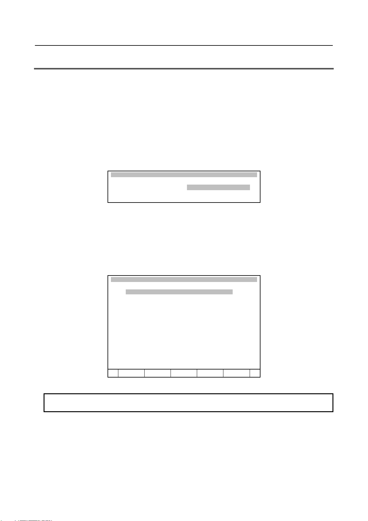
B-83525EN/01 MAINTENANCE 3.TROUBLESHOOTING
3.4 MASTERING
Mastering is needed if:
(1) The SRVO-062 BZAL or SRVO-038 pulse mismatch alarm occurs, or
(2) The Pulsecoder is replaced.
Item (1) requires quick mastering, while item (2) requires single axis or fixture position mastering.
(Single axis mastering is just for quick-fix purposes. After single axis mastering is used, fixture position
mastering should be performed later.)
The mastering procedure is described below. For details, refer to an applicable maintenance manual of
mechanical unit or operator's manual of controller.
Condition
System variable $MASTER_ENB must be set to 1 or 2.
SYSTEM Variables
272 $MASTER_ENB 1
Step
(1) Press <MENUS>.
(2) Select SYSTEM.
(3) Press F1, TYPE.
(4) Select Master/Cal you will see a screen similar to the following.
(5) Move the robot by jog feed to the mastering position. Release the brake on the manual brake control
screen if necessary.
SYSTEM Master/Cal
TORQUE = [ON ]
1 FIXTURE POSITION MASTER
2 ZERO POSITION MASTER
3 QUICK MASTER
4 SINGLE AXIS MASTER
5 SET QUICK MASTER REF
6 CALIBRATE
Press ‘ENTER’ or number key to select.
[ TYPE ] LOAD RES_PCA DONE
NOTE
Mastering cannot be performed until axis is rotated enough to establish a pulse.
- 17 -
Page 62

3.TROUBLESHOOTING MAINTENANCE B-83525EN/01
(6) Select "1 FIXTURE POSITION MASTER" and press the F4 key (yes). Mastering data is set.
SYSTEM Master/Cal
TORQUE = [ON ]
1 FIXTURE POSITION MASTER
2 ZERO POSITION MASTER
3 QUICK MASTER
4 SINGLE AXIS MASTER
5 SET QUICK MASTER REF
6 CALIBRATE
Robot Mastered! Mastering Data:
<-3105333> <-13216881> <22995280>
<-1354153> <0> <0>
[ TYPE ] LOAD RES_PCA DONE
(7) Select "6 CALIBRATE" and press the F4 key (yes). Calibration is performed.
Alternatively, to perform positioning, turn the power off, and then turn it on again. Calibration is
performed whenever the power is turned on.
SYSTEM Master/Cal
TORQUE = [ON ]
1 FIXTURE POSITION MASTER
2 ZERO POSITION MASTER
3 QUICK MASTER
4 SINGLE AXIS MASTER
5 SET QUICK MASTER REF
6 CALIBRATE
Robot Calibrated! Cur Jnt Ang(deg):
< 0.0000> < 24.6528> < -94.2241>
< 0.0000> < -85.7759> < 0.0000>
[ TYPE ] LOAD RES_PCA DONE
(8) Press F5 "DONE", after mastering.
(9) Restore the brake condition to its original condition.
- 18 -
Page 63

B-83525EN/01 MAINTENANCE 3.TROUBLESHOOTING
3.5 TROUBLESHOOTING USING THE ERROR CODE
SRVO-001 Operator panel E-stop
(Explanation) The emergency stop button on the operator's panel is pressed.
(Action 1) Release the emergency stop button pressed on the operator's panel.
(Action 2) Check the wires connecting between the emergency stop button and the emergency
stop board (CRT30) for continuity. If an open wire is found, replace the entire
harness.
(Action 3) Check the wires connecting between the teach pendant and the emergency stop board
(CRS36) for continuity. If an open wire is found, replace the entire harness.
(Action 4) With the emergency stop in the released position, check for continuity across the
terminals of the switch. If continuity is not found, the emergency stop button is
broken. Replace the emergency stop button or the operator's panel.
(Action 5) Replace the teach pendant.
(Action 6) Replace the emergency stop board.
Before executing the (Action 7), perform a complete controller back-up to save all your programs
and settings.
(Action 7) Replace the main board.
NOTE
If SRVO-001 is issued together with SRVO-213, a fuse may have blown. Take
the same actions as for SRVO-213.
Emergency stop
button
CRT30
CRS36
Fig.3.5 (a) SRVO-001 Operator panel E-stop
- 19 -
Page 64

3.TROUBLESHOOTING MAINTENANCE B-83525EN/01
SRVO-002 Teach pendant E-stop
(Explanation) The emergency stop button on the teach pendant was pressed.
(Action 1) Release the emergency stop button on the teach pendant.
(Action 2) Replace the teach pendant.
SRVO-003 DEADMAN switch released
(Explanation) The teach pendant is enabled, but the DEADMAN switch is not pressed.
Alternatively, the DEADMAN switch is pressed strongly.
(Action 1) Check the intermediate position of the DEADMAN switch on the teach pendant.
(Action 2) Check that the mode switch on the operator's panel and the enable/disable switch on
the teach pendant are at the correct positions.
(Action 3) Replace the teach pendant.
(Action 4) Check the mode switch connection and operation. If trouble is found, replace the
mode switch.
(Action 5) Replace the emergency stop board.
Enable/disable
Emergency stop
button
(Teach pendant)
2 mode switch
(Mode switch)
Emergency stop board
Fig.3.5 (b) SRVO-002 Teach pendant E-stop
SRV0-003 Mode switch and emergency stop board
Deadman switch
3 mode switch
- 20 -
Page 65

B-83525EN/01 MAINTENANCE 3.TROUBLESHOOTING
SRVO-004 Fence open
(Explanation) In the automatic operation mode, the safety fence contact connected to EAS1-EAS11
or EAS2-EAS21 of TBOP20 is open.
(Action 1) When a safety fence is connected, close the safety fence.
(Action 2) Check the cables and switches connected between EAS1 and EAS11 and between
EAS2 and EAS21 of the terminal block TBOP20 on the emergency stop board.
(Action 3) If the safety fence signal is not used, make a connection between EAS1 and EAS11
and between EAS2 and EAS21 of the terminal block TBOP20 on the emergency stop
board.
(Action 4) Check the mode switch. If trouble is found, replace the mode switch.
(Action 5) Replace the emergency stop board.
NOTE
If SRVO-004 is issued together with SRVO-213, a fuse may have blown. Take
the same actions as for SRVO-213.
TBOP20
No. Name
12 21
E-STOP
(ESPB)
11 2
10 11
9
8 21
FENCE
(EAS)
7 2
6 11
5
4 21
EMGIN
(EES)
3 2
2 11
1
2 mode switch
(Mode switch)
1
1
1
Fig.3.5 (c) SRVO-004 Fence open
3 mode switch
WARNING
In a system using the safety fence signal, it is very dangerous to disable the
signal when a connection is made between EAS1 and EAS11 and between
EAS2 and EAS21. Never make such an attempt. If a temporary connection is
needed for operation, separate safety measures must be taken.
VO-005 Robot overtravel
SR
(Explanation) The robot has moved beyond a hardware limit switch on the axes.
- 21 -
Page 66

3.TROUBLESHOOTING MAINTENANCE B-83525EN/01
(Action 1) 1) Select [System OT release] on the overtravel release screen to release each robot
axis from the overtravel state.
2) Hold down the shift key, and press the alarm release button to reset the alarm
condition.
3) Still hold down the shift key, and jog to bring all axes into the movable range.
(Action 2) Replace the limit switch.
(Action 3) Check the FS2 fuse on the servo amplifier. If the SRVO-214 fuse blown alarm is also
generated, the FS2 fuse has blown.
(Action 4) Check the EE connector.
(Action 5) Replace the 6-Axis servo amplifier.
(Action 6) Verify the following for connector RMP1 at the base of the robot:
1) There are no bent or dislocated pins in the male or female connectors.
2) The connector is securely connected.
Then verify that connectors CRF8 and CRM68 on the servo amplifier are securely
connected. Also, verify that the robot connection cable (RMP1) is in good condition,
and there are no cuts or kinks visible. Check the internal cable of the robot for a short
circuit or connection to ground.
NOTE
It is factory-placed in the overtravel state for packing purposes.
If the Overtravel signal is not in use, it may have been disabled by
short-circuiting in the mechanical unit.
SRVO-006 Hand broken
(Explanation) The safety joint (if in use) might have been broken. Alternatively, the HBK signal on
the robot connection cable might be a ground fault or a cable disconnection.
(Action 1) Hold down the shift key, and press the alarm release button to reset the alarm
condition. Still hold down the shift key, and jog the tool to the work area.
1) Replace the safety joint.
2) Check the safety joint cable.
(Action 2) Replace the 6-Axis servo amplifier.
(Action 3) Verify the following for connector RMP1 at the base of the robot:
1) There are no bent or dislocated pins in the male or female connectors.
2) The connector is securely connected.
Then verify that connectors CRF8 and CRM68 on the servo amplifier are securely
connected. Also, verify that the robot connection cable (RMP1) is in good condition,
and there are no cuts or kinks visible. Check the internal cable of the robot for a short
circuit or connection to ground.
NOTE
If the Hand broken signal is not in use, it can be disabled by software setting.
Refer to Subsection 5.6.3 in CONNECTIONS to disable the Hand broken signal.
- 22 -
Page 67

B-83525EN/01 MAINTENANCE 3.TROUBLESHOOTING
6-Axis servo amplifier
Connector(CRM68)
Connector(CRF8)
FS2 (3.2A)
(6-Axis servo amplifier)
Fig.3.5 (d) SRVO-005 Robot overtravel
SRVO-006 Hand broken
- 23 -
Page 68

3.TROUBLESHOOTING MAINTENANCE B-83525EN/01
SRVO-007 External E-stop
(Explanation) On the terminal block TBOP20 of the emergency stop board, no connection of
external emergency stop is made between EES1 and EES11, EES2 and EES21.
(Action 1) If an external emergency stop switch is connected, release the switch.
(Action 2) Check the switch and cable connected to EES1-EES11 and EES2-EES21 on
TBOP20 of the emergency stop board.
(Action 3) When this signal is not used, make a connection between EES1 and EES11, EES2
and EES21.
(Action 4) Replace the emergency stop board.
NOTE
If SRVO-007 is issued together with SRVO-213, a fuse may have blown. Take
the same actions as for SRVO-213.
TBOP20
No. Name
12 21
E-STOP
(ESPB)
11 2
10 11
9
8 21
FENCE
(EAS)
7 2
6 11
5
4 21
EMGIN
(EES)
3 2
2 11
1
1
1
1
Fig.3.5 (e) SRVO-007 External E-stop
WARNING
In a system using the external emergency stop signal, it is very dangerous to
disable the signal when a connection is made between EES1 and EES11 and
between EES2 and EES21. Never make such an attempt. If a temporary
connection is needed for operation, separate safety measures must be taken.
- 24 -
Page 69

B-83525EN/01 MAINTENANCE 3.TROUBLESHOOTING
SRVO-009 Pneumatic pressure abnormal
(Explanation) An abnormal air pressure was detected. The input signal is located on the end EE
interface of the robot. Refer to the manual of your robot.
(Action 1) If an abnormal air pressure is detected, check the cause.
(Action 2) Check the EE connector.
(Action 3) Check the robot connection cable (RMP1) and the internal cable of the robot for a
ground fault or a cable disconnection. If a fault or a disconnection is detected,
replace the cable.
(Action 4) Replace the 6-Axis servo amplifier.
(Action 5) Replace the internal cables of the robot.
NOTE
Pneumatic pressure alarm input is on the EE interface. Please refer to the
manual of your robot.
6-Axis servo amplifier
Fig.3.5 (f) SRVO-009 Pneumatic pressure alarm
- 25 -
Page 70

3.TROUBLESHOOTING MAINTENANCE B-83525EN/01
SRVO-014 Fan motor abnormal
(Explanation) When a fan motor stops on backplane unit, Teach pendant shows the following
message. In one minutes from occurring of alarm, robot stops and cannot be operated
from TP. The robot can be recovered by replacing a fan motor. Number in the
bracket indicates which fan is abnormal.
(1): FAN0
(2): FAN1
(3): both fans
(Action 1) Check the fan motor and its cables. Replace them if necessary.
(Action 2) Replace the fan board.
Before executing the (Action 3), perform a complete controller back up to save all your programs
and settings.
(Action 3) Replace the main board.
Fan motor (FAN0)
Fan motor (FAN1)
Main board
Fig.3.5 (g) SRVO-014 Fan motor abnormal
- 26 -
Page 71

B-83525EN/01 MAINTENANCE 3.TROUBLESHOOTING
SRVO-015 System over heat
(Explanation) The temperature in the controller exceeds the specified value. In one minutes from
occurring of alarm, robot stops and cannot be operated from TP.
(Action 1) If the ambient temperature is higher than specified (45°C), cool down the ambient
temperature.
(Action 2) If the fan motor is not running, check it and its cables. Replace them if necessary.
Before executing the (Action 3), perform a complete controller backup to save all your programs and
settings.
(Action 3) Replace the main board. (The thermostat on the main board may be faulty.)
Fan motor
Main board
Door fan
Heat exchanger
Fig.3.5 (h) SRVO-015 SYSTEM OVER HEAT
- 27 -
Page 72

3.TROUBLESHOOTING MAINTENANCE B-83525EN/01
SRVO-018 Brake abnormal
(Explanation) An excessive brake current is detected. The ALM LED (SVALM) on the 6-Axis
servo amplifier is lit.
(Action 1) Check the robot connection cable (RMP1) and the internal cable of the robot and
motor brakes connected to CRR88 connector on the 6-Axis servo amplifier.
If a short-circuit or grounding fault is found, replace the failed part.
(Action 2) Check the cables and motor brakes connected to CRR65A, CRR65B connector on
the 6-Axis servo amplifier. If a short-circuit or grounding fault is found, replace the
failed part.
(Action 3) Replace the 6-Axis servo amplifier.
CAUTION
This error can be caused by the optional brake release unit if the on/off switch is
left in on position while the operator attempts to jog the robot. To recover, turn
the brake release unit off and cycle the controller power.
SRVO-021 SRDY off (Group: i Axis: j)
(Explanation) The HRDY is on and the SRDY is off, although there is no other cause of an alarm.
(HRDY is a signal with which the host detects the servo system whether to turn on or
off the servo amplifier magnetic contactor. SRDY is a signal with which the servo
system informs the host whether the magnetic contactor is turned on.)
If the servo amplifier magnetic contactor cannot be turned on when directed so, it is
most likely that a servo amplifier alarm has occurred. If a servo amplifier alarm has
been detected, the host will not issue this alarm (SRDY off). Therefore, this alarm
indicates that the magnetic contactor cannot be turned on for an unknown reason.
(Action 1) Make sure that the emergency stop board connectors CP5A, CRMA92, CRMB22,
and 6-Axis servo amplifier CRMA91 are securely attached to the servo amplifier.
(Action 2) It is possible that an instant disconnection of power source causes this alarm. Check
whether an instant disconnection occurred.
(Action 3) Replace the E-stop unit.
(Action 4) Replace the servo amplifier.
SRVO-022 SRDY on (Group: i Axis: j)
(Explanation) When the HRDY is about to go on, the SRDY is already on. (HRDY is a signal
with which the host directs the servo system whether to turn on or off the servo
amplifier magnetic contactor. SRDY is a signal with which the servo system
informs the host whether the magnetic contactor is turned on.)
(Action 1) Replace the servo amplifier as the alarm message.
SRVO-023 Stop error excess (G:i A:j)
(Explanation) When the servo is at stop, the position error is abnormally large.
Check whether the brake is released through the clack sound of the brake or
vibration.
In case that the brake is not released.
(Action 1) If the brake is not released, check the continuity of the brake line in the robot
connection cable and the robot internal cable.
(Action 2) If the disconnection is not found, replace the 6-Axis servo amplifier or the servo
motor.
In case that the brake is released.
(Action 1) Check whether the obstacle disturbs the robot motion.
(Action 2) Make sure that connectors CNJ1A-CNJ6 are securely attached to the 6-Axis servo
amplifier.
- 28 -
Page 73

B-83525EN/01 MAINTENANCE 3.TROUBLESHOOTING
(Action 3) Check the continuity of the robot connection cable and the internal robot power
cable.
(Action 4) Check to see if the load is greater than the rating. If greater, reduce it to within the
rating. (If the load is too great, the torque required for acceleration / deceleration
becomes higher than the capacity of the motor.
As a result, the motor becomes unable to follow the command, and an alarm is
issued.)
(Action 5) Check the input voltage to the controller is within the rated voltage and no phase is
lack.
Check each phase voltage of the CRR68A or CRR68B connector of the three-phase
power (200 VAC) input to the 6-Axis servo amplifier. If it is 210 VAC or lower,
check the line voltage. (If the voltage input to the 6-Axis servo amplifier becomes
low, the torque output also becomes low. As a result, the motor may become unable
to follow the command, hence possibly causing an alarm.).
(Action 6) Replace the servo amplifier.
(Action 7) Replace the motor of the alarm axis.
NOTE
Incorrect setting of the brake number causes this alarm.
6-Axis servo amplifier
Fig.3.5 (i) SRVO-018 Brake abnormal
SRVO-021 SRDY off
SRVO-022 SRDY on
SRVO-023 Stop error excess
- 29 -
Page 74

3.TROUBLESHOOTING MAINTENANCE B-83525EN/01
SRVO-024 Move error excess (G:i A:j)
(Explanation) When the robot is running, its position error is greater than a specified value
($PARAM _ GROUP. $MOVER _ OFFST). It is likely that the robot cannot
follow the speed specified by program.
(Action 1) Take the same actions as SRVO-023.
SRVO-027 Robot not mastered (Group: i)
(Explanation) An attempt was made to calibrate the robot, but the necessary adjustment had not
been completed.
(Action) Check whether the mastering is valid. If the mastering is invalid, master the robot.
WARNING
If the position data is incorrect, the robot or additional axis can operate
abnormally, set the position data correctly. Otherwise, you could injure personnel
or damage equipment.
SRVO-030 Brake on hold (Group: i)
(Explanation) If the temporary halt alarm function is enabled ($SCR.$BRKHOLD ENB=1),
SRVO-030 is issued when a temporary halt occurs. When this function is not used,
disable the setting.
(Action) Disable [Servo-off in temporary halt] on the general item setting screen [6 General
Setting Items].
SRVO-033 Robot not calibrated (Group: i)
(Explanation) An attempt was made to set up a reference point for quick mastering, but the robot
had not been calibrated.
(Action) Calibrate the robot.
1. Supply power.
2. Set up a quick mastering reference point using [Positioning] on the positioning menu.
SRVO-034 Ref pos not set (Group: i)
(Explanation) An attempt was made to perform quick mastering, but the reference point had not
been set up.
(Action) Set up a quick mastering reference point on the positioning menu.
SRVO-036 Inpos time over (G:i A:j)
(Explanation) The robot did not get to the effective area ($PARAM _ GROUP.$ STOPTOL) even
after the position check monitoring time ($PARAM _ GROUP. $INPOS _ TIME)
elapsed.
(Action) Take the same actions as for SRVO-023 (large position error at a stop).
SRVO-037 IMSTP input (Group: i)
(Explanation) The *IMSTP signal for a peripheral device interface was input.
(Action) Turn on the *IMSTP signal.
SRVO-038 Pulse mismatch (Group: i Axis: j)
(Explanation) The pulse count obtained when power is turned off does not match the pulse count
obtained when power is applied. This alarm is asserted after exchange the
Pulsecoder or battery for back up of the Pulsecoder data or loading back up data to
the Main Board.
Check the alarm history.
- 30 -
Page 75

B-83525EN/01 MAINTENANCE 3.TROUBLESHOOTING
(Action 1) If the brake number is set to the non-brake motors, this alarm may occur. Check the
software setting of the brake number.
(Action 2) In case the robot has been moved by using the brake release unit while the power is
off or when restoring the back-up data to the main board, this alarm may occur.
Remaster the robot.
(Action 3) If the robot has been moved because the brake failed, this alarm may occur. Check
the cause of the brake trouble. Then remaster the robot.
(Action 4) Replace the Pulsecoder and master the robot.
SRVO-043 DCAL alarm (Group: i Axis: j)
(Explanation) The regenerative discharge energy was too high to be dissipated as heat. (To run
the robot, the servo amplifier supplies energy to the robot. When going down the
vertical axis, the robot operates from the potential energy. If a reduction in the
potential energy is higher than the energy needed for acceleration, the servo amplifier
receives energy from the motor. A similar phenomenon occurs even when no
gravity is applied, for example, at deceleration on a horizontal axis. The energy that
the servo amplifier receives from the motor is called the regenerative energy. The
servo amplifier dissipates this energy as heat. If the regenerative energy is higher
than the energy dissipated as heat, the difference is stored in the servo amplifier,
causing an alarm.)
(Action 1) This alarm may occur if the axis is subjected to frequent acceleration/deceleration or
if the axis is vertical and generates a large amount of regenerative energy.
If this alarm has occurred, relax the service conditions.
(Action 2) Check fuse (FS3) in the 6-Axis servo amplifier. If it has blown, remove the cause,
and replace the fuse.
(Action 3) The ambient temperature is excessively high. Or the regenerative resistor can't be
cooled effectively. Check the external fan unit, and replace it if it stops. Clean up the
fun unit, the regenerative resistor and the louver if they are dirty.
(Action 4) Make sure that the 6-Axis servo amplifier CRR63A and CRR63B connectors are
connected tightly. Then detach the cable from CRR63A and CRR63B connectors on
the 6-Axis servo amplifier, and check for continuity between pins 1 and 2 of the
cable-end connector. If there is no continuity between the pins, replace the
regenerative resistor.
(Action 5) Make sure that the 6-Axis servo amplifier CRRA11A and CRRA11B are connected
tightly, then detach the cables from CRRA11A and CRRA11B on the 6-Axis servo
amplifier and check the resistance between pins 1 and 3 of each cable end connector.
If the resistance is not 6.5Ω, replace the regenerative resistor. CRRA11B may not
be used depending on the robot model.
(Action 6) Replace the 6-Axis servo amplifier.
6-Axis servo amplifier
Fig.3.5 (j) SRVO-043 DCAL alarm
E-stop unit
- 31 -
Regenarative resistor
Page 76

3.TROUBLESHOOTING MAINTENANCE B-83525EN/01
SRVO-044 DCHVAL%s alarm (G:%d A:%d)
(Explanation) The DC voltage (DC link voltage) of the main circuit power supply is abnormally
high.
(Action 1) Check the input voltage to the controller is within the rated voltage. And check the
setting of the transformer is correct.
(Action 2) Check the three-phase input voltage at the 6-Axis servo amplifier. If it is 240 VAC
or higher, check the line voltage. (If the three-phase input voltage is higher than
240 VAC, high acceleration/deceleration can cause in this alarm.)
(Action 3) Check that the load weight is within the rating. If it is higher than the rating, reduce
it to within the rating. (If the machine load is higher than the rating, the
accumulation of regenerative energy might result in the HVAL alarm even when the
three-phase input voltage is within the rating.)
(Action 4) Check that the CRRA11A and CRRA11B connectors of the 6-Axis servo amplifier
are attached firmly. Next, detach the cables then check the continuity between pins.
If the resistance is not 6.5Ω, replace the regenerative resistor. CRRA11B may not be
used depending on the robot model.
(Action 5) Replace the 6-Axis servo amplifier.
SRVO-045 HCAL alarm (Group: i Axis: j)
(Explanation) Abnormally high current flowed in the main circuit of the servo amplifier.
(Action 1) Turn off the power, and disconnect the power cable from the servo amplifier
indicated by the alarm message. (And disconnect the brake cable (CRR88 on the
6-Axis servo amplifier) to avoid the axis falling unexpectedly.) Supply power and
see if the alarm occurs again. If the alarm occurs again, replace the servo amplifier.
(Action 2) Turn off the power and disconnect the power cable from the servo amplifier
indicated by the alarm message, and check the insulation of their U, V, W and the
GND lines each other. If there is a short-circuit, replace the power cable.
(Action 3) Turn off the power and disconnect the power cable from the servo amplifier by the
alarm message, and measure the resistance between their U and V, V and W and W
and U with an ohmmeter that has a very low resistance range. If the resistances at the
three places are different from each other, the motor, the power cable is defective.
Check each item in detail and replace it if necessary.
- 32 -
Page 77

B-83525EN/01 MAINTENANCE 3.TROUBLESHOOTING
SRVO-046 OVC alarm (Group: i Axis: j)
(Explanation) This alarm is issued to prevent the motor from thermal damage that might occur
when the root meant square current calculated within the servo system is out of the
allowable range.
(Action 1) Check the operating condition for the robot and relax the service condition if possible.
If the load or operating condition has exceeded the rating, reduce the load or relax
the operating condition to meet the rating.
(Action 2) Check whether the voltage input to the controller is within the rated voltage.
(Action 3) Check whether the brake of the corresponding axis is released.
(Action 4) Check whether there is a factor that has increased the mechanical load on the
corresponding axis.
(Action 5) Replace the servo amplifier.
(Action 6) Replace the motor of the corresponding axis.
(Action 7) Replace the E-stop unit
(Action 8) Replace the motor power line (robot connection cable) of the corresponding axis.
(Action 9) Replace the motor power line and brake line (internal cable of the robot) of the
corresponding axis.
6-Axis servo amplifier
Fig.3.5(k) SRVO-044 HVAL alarm
SRVO-045 HCAL alarm
SRVO-046 OVC alarm
- 33 -
Page 78

3.TROUBLESHOOTING MAINTENANCE B-83525EN/01
Reference
Relationships among the OVC, OHAL, and HC alarms
- Overview
This section points out the differences among the OVC, OHAL, and HC alarms and describes the purpose
of each alarm.
- Alarm detection section
Abbreviation Designation Detection section
OVC Overcurrent alarm Servo software
OHAL Overheat alarm Thermal relay in the motor
Thermal relay in the servo amplifier
Thermal relay in the separate regenerative resister
HC High current alarm Servo amplifier
- Purpose of each alarm
1) HC alarm (high current alarm)
If high current flow in a power transistor momentarily due to abnormality or noise in the control
circuit, the power transistor and rectifier diodes might be damaged, or the magnet of the motor might
be degaussed. The HC alarm is intended to prevent such failures.
2) OVC and OHAL alarms (overcurrent and overload alarms)
The OVC and OHAL alarms are intended to prevent overheat that may lead to the burnout of the
motor winding, the breakdown of the servo amplifier transistor, and the separate regenerative
resistor.
The OHAL alarm occurs when each built-in thermal relay detects a temperature higher than the rated
value. However, this method is not necessarily perfect to prevent these failures. For example, if
the motor frequently repeats to start and stop, the thermal time constant of the motor, which has a
large mass, becomes higher than the time constant of the thermal relay, because these two
components are different in material, structure, and dimension. Therefore, if the motor continues to
start and stop within a short time as shown in Fig. 3.5 (p), the temperature rise in the motor is steeper
than that in the thermal relay, thus causing the motor to burn before the thermal relay detects an
abnormally high temperature.
Temperature
Start StartStartStop Stop
Thermal time constant of the
Temperature at
which the winding
starts to burn
Fig.3.5 (l) Relationship between the temperatures of the motor and thermal relay on start/stop cycles
motor is high.
Thermal time constant of the
thermal relay is low.
Time
To prevent the above defects, software is used to monitor the current in the motor constantly in order to
estimate the temperature of the motor. The OVC alarm is issued based on this estimated temperature.
This method estimates the motor temperature with substantial accuracy, so it can prevent the failures
described above.
- 34 -
Page 79

B-83525EN/01 MAINTENANCE 3.TROUBLESHOOTING
To sum up, a double protection method is used; the OVC alarm is used for protection from a short-time
overcurrent, and the OHAL alarm is used for protection from long-term overload. The relationship
between the OVC and OHAL alarms is shown in Fig.3.5 (q).
Current
Limit current
Rated continuous current
Protection area for
the motor and servo
amplifier
Protection by the OHAL
Protection by
the OVC
Time
Fig.3.5 (m) Relationship between the OVC and OHAL alarms
NOTE
The relationship shown in Fig.3.5 (q) is taken into consideration for the OVC
alarm. The motor might not be hot even if the OVC alarm has occurred. In
this case, do not change the parameters to relax protection.
- 35 -
Page 80

3.TROUBLESHOOTING MAINTENANCE B-83525EN/01
SRVO-047 LVAL alarm (Group: i Axis: j)
(Explanation) The control power supply voltage (+5 V, etc.) supplied from the power supply circuit
in the servo amplifier is abnormally low.
(Action 1) Replace the servo amplifier.
(Action 2) Replace the power supply unit.
6-Axis servo amplifier
Fig.3.5 (n) SRVO-047 LVAL alarm
Power supply unit
- 36 -
Page 81

B-83525EN/01 MAINTENANCE 3.TROUBLESHOOTING
SRVO-049 OHAL1 alarm (G: i A: j)
(Explanation) The 6-Axis servo amplifier detects transformer overheat signal.
(Action 1) Check that a connection is made between the 6-Axis servo amplifier CRMA91.
(Action 2) Replace the 6-Axis servo amplifier.
SRVO-050 Collision Detect alarm (Grp:i Ax:j)
(Explanation) The disturbance torque estimated by the servo software is abnormally high. (A
collision has been detected.)
(Action 1) Check whether the robot has collided and also check whether there is a factor that
has increased the mechanical load on the corresponding axis.
(Action 2) Check whether the load settings are valid.
(Action 3) Check whether the brake of the corresponding axis is released.
(Action 4) If the load weight exceeds the rated range, decrease it to within the limit.
(Action 5) Check whether the voltage input to the controller is within the rated voltage.
(Action 6) Replace the servo amplifier.
(Action 7) Replace the motor of the corresponding axis.
(Action 8) Replace the E-stop unit.
(Action 9) Replace the motor power line (robot connection cable) of the corresponding axis.
(Action 10) Replace the motor power line and brake line (internal cable of the robot) of the
corresponding axis.
SRVO-051 CUER alarm (Group: i Axis: j)
(Explanation) The offset of the current feedback value is abnormally high.
(Action) Replace the servo amplifier.
6-Axis servo amplifier E-stop unit
Fig.3.5 (o) SRVO-049 OHAL1 alarm
SRVO-050 CLALM alarm
SRVO-051 CUER alarm
- 37 -
Page 82

3.TROUBLESHOOTING MAINTENANCE B-83525EN/01
SRVO-055 FSSB com error 1 (G: i A: j)
(Explanation) A communication error has occurred between the main board and servo amplifier.
(Action 1) Check the optical fiber cable between the axis control card and servo amplifier.
Replace it if it is faulty.
(Action 2) Replace the axis control card on the main board.
(Action 3) Replace the servo amplifier.
SRVO-056 FSSB com error 2 (G: i A: j)
(Explanation) A communication error has occurred between the main board and servo amplifier.
(Action 1) Check the optical fiber cable between the axis control card and servo amplifier.
Replace it if it is faulty.
(Action 2) Replace the axis control card on the main board.
(Action 3) Replace the servo amplifier.
SRVO-057 FSSB disconnect (G:i A: j)
(Explanation) Communication was interrupted between the main board and servo amplifier.
(Action 1) Check whether fuse (FS1) on the 6-Axis servo amplifier has blown. If the fuse has
blown, replace the 6-Axis servo amplifier including the fuse.
(Action 2) Check the optical fiber cable between the axis control card and servo amplifier.
Replace it if it is faulty.
(Action 3) Replace the axis control card on the main board.
(Action 4) Replace the servo amplifier.
(Action 5) Check for a point where the robot connection cable (RMP1) or an internal cable
running to each Pulsecoder through the robot mechanical section is grounded.
Before continuing to the next step, perform a complete controller back up to save all your programs
and settings.
(Action 6) Replace the main board.
SRVO-058 FSSB xx init error (yy)
(Explanation) Communication was interrupted between the main board and servo amplifier.
(Action 1) Check whether fuse (FS1) on the 6-Axis servo amplifier has blown. If the fuse has
blown, replace the 6-Axis servo amplifier including the fuse.
(Action 2) Turn off the power and disconnect the CRF8 connector on the 6-Axis servo amplifier.
Then check whether this alarm occurs again. (Ignore the alarm SRVO-068 because of
disconnecting the CRF8 connector.)
If this alarm does not occur, the robot connection cable (RMP1) or the internal cable
of the robot may be short-circuited to the ground. Check the cables and replace it if
necessary.
(Action 3) Check whether the LED (P5V and P3.3V) on the 6-Axis servo amplifier is lit. If they
are not lit, the DC power is not supplied to the 6-Axis servo amplifier.
Make sure the connector CP5 on the power supply unit and the connector CXA2B on
the 6-Axis servo amplifier are connected tightly. If they are connected tightly,
replace the 6-Axis servo amplifier.
(Action 4) Check the optical fiber cable between the axis control card and servo amplifier.
Replace it if it is faulty.
(Action 5) Replace the axis control card on the main board.
(Action 6) Replace the 6-Axis servo amplifier.
(Action 7) If the other units (the servo amplifier for the auxiliary axis and the line tracking
interface) are connected in the FSSB optical communication, disconnect these units
and connect only 6-Axis servo amplifier for the robot. Then turn on the power. If this
alarm does not occur, search the failed unit and replace it.
- 38 -
Page 83

B-83525EN/01 MAINTENANCE 3.TROUBLESHOOTING
A
Before executing the (Action 8), perform a complete controller back up to save all your programs
and settings.
(Action 8) Replace the main board.
Main board
6-Axis servo amplifier
xis control card
Fig.3.5 (p) SRVO-055 FSSB com error 1
(Main board)
SRVO-056 FSSB com error 2
SRVO-057 FSSB disconnect
SRVO-058 FSSB init error
- 39 -
Page 84

3.TROUBLESHOOTING MAINTENANCE B-83525EN/01
SRVO-059 Servo amp init error
(Explanation) Servo amplifier initialization is failed.
(Action 1) Check the wiring of the servo amplifier.
(Action 2) Replace the servo amplifier.
(Action 3) Replace the line tracking board. (If installed)
SRVO-062 BZAL alarm (Group: i Axis: j)
(Explanation) This alarm occurs if battery for Pulsecoder absolute-position backup is empty.
A probable cause is a broken battery cable or no batteries in the robot.
(Action 1) Replace the battery in the battery box of the robot base.
(Action 2) Replace the Pulsecoder with which an alarm has been issued.
(Action 3) Check whether the robot internal cable for feeding power from the battery to the
Pulsecoder is not disconnected and grounded. If an abnormality is found, replace
the cable.
CAUTION
After correcting the cause of this alarm, set the system variable
($MCR.$SPC_RESET) to TRUE then turn on the power again. Mastering is
needed.
SRVO-064 PHAL alarm (Group: i Axis: j)
(Explanation) This alarm occurs if the phase of the pulses generated in the Pulsecoder is abnormal.
(Action) Replace the Pulsecoder with which an alarm has been issued.
NOTE
This alarm might accompany the DTERR, CRCERR, or STBERR alarm. In this
case, however, there is no actual condition for this alarm.
SRVO-065 BLAL alarm (Group: i Axis: j)
(Explanation) The battery voltage for the Pulsecoder is lower than the rating.
(Action) Replace the battery.
(If this alarm occurs, turn on the power and replace the battery as soon as possible. A
delay in battery replacement may result in the BZAL alarm being detected. In this
case, the position data will be lost. Once the position data is lost, mastering will
become necessary.
SRVO-067 OHAL2 alarm (Grp:i Ax:j)
(Explanation) The temperature inside the Pulsecoder or motor is abnormally high, and the built-in
thermostat has operated.
(Action 1) Check the robot operating conditions. If a condition such as the duty cycle and load
weight has exceeded the rating, relax the robot load condition to meet the allowable
range.
(Action 2) When power is supplied to the motor after it has become sufficiently cool, if the
alarm still occurs, replace the motor.
- 40 -
Page 85

B-83525EN/01 MAINTENANCE 3.TROUBLESHOOTING
SRVO-068 DTERR alarm (Grp:i Ax:j)
(Explanation) The serial Pulsecoder does not return serial data in response to a request signal.
(Action 1) Make sure that the robot connection cable (RMP1) connector (CRF8) of 6-Axis
servo amplifier and the connector (motor side) are connected tightly.
(Action 2) Check that the shielding of the robot connection cable (RMP1) is grounded securely
in the cabinet.
(Action 3) Replace the Pulsecoder.
(Action 4) Replace the servo amplifier.
(Action 5) Replace the robot connection cable (RMP1).
(Action 6) Replace the internal cable of the robot (for the Pulsecoder).
SRVO-069 CRCERR alarm (Grp:i Ax:j)
(Explanation) The serial data has disturbed during communication.
(Action) See actions on SRVO-068
SRVO-070 STBERR alarm (Grp:i Ax:j)
(Explanation) The start and stop bits of the serial data are abnormal.
(Action) See actions on SRVO-068
6-Axis servo amplifier
Fig.3.5 (q) SRVO-059 Servo amp init error
SRVO-070 STBERR alarm
- 41 -
Page 86

3.TROUBLESHOOTING MAINTENANCE B-83525EN/01
SRVO-071 SPHAL alarm (Grp:i Ax:j)
(Explanation) The feedback speed is abnormally high.
(Action) Action as same as the SRVO-068.
NOTE
If this alarm occurs together with the PHAL alarm (SRVO-064), this alarm does
not correspond to the major cause of the failure.
SRVO-072 PMAL alarm (Group: i Axis: j)
(Explanation) It is likely that the Pulsecoder is abnormal.
(Action) Replace the Pulsecoder and remaster the robot.
SRVO-073 CMAL alarm (Group: i Axis: j)
(Explanation) It is likely that the Pulsecoder is abnormal or the Pulsecoder has malfunctioned due
to noise.
(Action 1) Check whether the connection of the controller earth is good. Check the earth cable
connection between controller and robot connection cables are connected securely to
the grounding plate.
(Action 2) Reinforce the earth of the motor flange. (In case of Auxiliary axis)
(Action 3) Replace the Pulsecoder.
SRVO-074 LDAL alarm (Group: i Axis: j)
(Explanation) The LED in the Pulsecoder is broken.
(Action) Replace the Pulsecoder, and remaster the robot.
SRVO-075 Pulse not established (G: i A: j)
(Explanation) The absolute position of the Pulsecoder cannot be established.
(Action) Reset the alarm, and jog the axis on which the alarm has occurred until the same
alarm will not occur again.
SRVO-076 Tip Stick Detection (G: i A: j)
(Explanation) An excessive disturbance was assumed in servo software at the start of operation.
(An abnormal load was detected. The cause may be welding.)
(Action 1) Check whether the robot has collided. Or check whether the machinery load of the
corresponding axis is increased.
(Action 2) Check whether the load settings are valid.
(Action 3) Check whether the brake of the corresponding axis is released.
(Action 4) Check whether the load weight is within the rated range. If the weight exceeds the
upper limit, decrease it to the limit.
(Action 5) Check whether the voltage input to the controller is within the rated voltage.
(Action 6) Replace the servo amplifier.
(Action 7) Replace the corresponding servo motor.
(Action 8) Replace the E-stop unit.
(Action 9) Replace the power cable of the robot connection cable in which the corresponding
axis is connected.
(Action 10) Replace the internal cable of the robot (power/brake) in which the corresponding axis
is connected.
- 42 -
Page 87

B-83525EN/01 MAINTENANCE 3.TROUBLESHOOTING
6-Axis servo amplifier E-stop unit
Fig.3.5 (r) SRVO-076 Tip stick detection
SRVO-081 EROFL alarm (Track enc: i)
(Explanation) The pulse counter for line tracking has overflowed.
(Action 1) Check whether the condition of the line tracking exceeds the limitation.
(Action 2) Replace the Pulsecoder.
(Action 3) Replace the line tracking board.
SRVO-082 DAL alarm (Track encoder: i)
(Explanation) The line tracking Pulsecoder has not been connected.
(Action 1) Check the connection cable at each end (the line tracking board and the motor side)
(Action 2) Check whether the shielding of the connection cable is connected securely to the
grounding plate.
(Action 3) Replace the line tracking cable.
(Action 4) Replace the Pulsecoder.
(Action 5) Replace the line tracking board.
SRVO-084 BZAL alarm (Track enc: i)
(Explanation) This alarm occurs if the backup battery for the absolute position of the Pulsecoder
has not been connected. See the description about the BZAL alarm (SRVO-062).
SRVO-087 BLAL alarm (Track enc: i)
(Explanation) This alarm occurs if the voltage of the backup battery for the absolute position of the
Pulsecoder is low. See the description about the BLAL alarm (SRVO-065).
SRVO-089 OHAL2 alarm (Track enc: i)
(Explanation) The motor has overheated. When power is supplied to the Pulsecoder after it has
become sufficiently cool, if the alarm still occurs. See the description about the
OHAL2 alarm (SRVO-067).
- 43 -
Page 88

3.TROUBLESHOOTING MAINTENANCE B-83525EN/01
SRVO-090 DTERR alarm (Track enc: i)
(Explanation) Communication between the Pulsecoder and line tracking board is abnormal. See
the SRVO-068 DTERR alarm.
(Action 1) Check the connection cable at each end (the line tracking board and the Pulsecoder)
(Action 2) Check whether the shielding of the connection cable is connected securely to the
grounding plate.
(Action 3) Replace the Pulsecoder.
(Action 4) Replace the line tracking cable.
(Action 5) Replace the line tracking board.
SRVO-091 CRCERR alarm (Track enc: i)
(Explanation) Communication between the Pulsecoder and line tracking board is abnormal.
(Action) Action as same as the SRVO-090.
SRVO-092 STBERR alarm (Track enc: i)
(Explanation) Communication between the Pulsecoder and line tracking board is abnormal.
(Action) Action as same as the SRVO-090.
SRVO-093 SPHAL alarm (Track enc: i)
(Explanation) This alarm occurs if the current position data from the Pulsecoder is higher than the
previous position data.
(Action) Action as same as the SRVO-090.
SRVO-094 PMAL alarm (Track enc: i)
(Explanation) It is likely that the Pulsecoder is abnormal. See the description about the PMAL
alarm (SRVO-072).
SRVO-095 CMAL alarm (Track enc: i)
(Explanation) It is likely that the Pulsecoder is abnormal or the Pulsecoder has malfunctioned due
to noise. See the description about the CMAL alarm (SRVO-073).
(Action 1) Reinforce the earth of the flange of the Pulsecoder.
(Action 2) Replace the Pulsecoder.
SRVO-096 LDAL alarm (Track enc: i)
(Explanation) The LED in the Pulsecoder is broken. See the description about the LDAL alarm
(SRVO-074).
SRVO-097 Pulse not established (enc: i)
(Explanation) The absolute position of the Pulsecoder cannot be established. See the description
about (SRVO-075). Pulse not established.
(Action 1) Reset the alarm, and jog the axis on which the alarm has occurred until the same
alarm does not occur again. (Jog one motor revolution)
- 44 -
Page 89

B-83525EN/01 MAINTENANCE 3.TROUBLESHOOTING
SRVO-105 Door open or E.Stop
(Explanation) The cabinet door is open.
- When the door switch is not mounted skip Action 1 and 2 and start from Action 3
(Action 1) When the door is open, close it.
(Action 2) Check the door switch and door switch connection cable. If the switch or cable is
faulty, replace it.
(Action 3) Check that the CRMA92, CRMB8 connectors on the E-STOP unit and CRMA91 on
the 6-Axis servo amplifier are connected securely.
(Action 4) Replace the emergency stop board.
(Action 5) Replace the 6- Axis servo amplifier.
6-Axis servo amplifier
Fig.3.5 (s) SRVO-105 Door open or E-stop
E-stop unit
(Emergency stop board)
- 45 -
Page 90

3.TROUBLESHOOTING MAINTENANCE B-83525EN/01
SRVO-123 Fan motor rev slow down(%d)
(Explanation) The rotation speed of fan motor is slow down.
(Action 1) Check the fan motor and its cables. Replace them if necessary.
(Action 2) Replace the backplane unit.
Before executing the (Action 3), perform a complete controller back up to save all your programs
and settings.
(Action 3) Replace the main board.
Fan motor
Main board
Fig.3.5 (t) SRVO-123 Fan motor rev slow down(%d)
SRVO-134 DCLVAL alarm (G:%d A:%d)
(Explanation) The DC voltage (DC link voltage) of the main circuit power supply for the servo
amplifier is abnormally low.
(Action 1) It is possible that an instant disconnection of power source causes this alarm. Check
whether an instant disconnection occurred.
(Action 2) Check the input voltage to the controller is within the rated voltage.
(Action 3) Modify the program in order that robot and the auxiliary axis do not accelerate
simultaneously in the system with the auxiliary axis.
(Action 4) Replace the E-stop unit.
(Action 5) Replace the servo amplifier.
- 46 -
Page 91

B-83525EN/01 MAINTENANCE 3.TROUBLESHOOTING
SRVO-156 IPMAL alarm (G: i A: j)
(Explanation) Abnormally high current flowed through the main circuit of the servo amplifier.
(Action 1) Turn off the power, and disconnect the power cable from the servo amplifier
indicated by the alarm message. (And disconnect the brake cable (CRR88 on the
servo amplifier) to avoid the axis falling unexpectedly.) Turn on the power, and if the
alarm occurs again, replace the servo amplifier.
(Action 2) Turn off the power and disconnect the power cable from the servo amplifier
indicated by the alarm message, and check the insulation of their U, V, W and the
GND lines each other. If there is a short-circuit, replace the power cable.
(Action 3) Turn off the power and disconnect the power cable from the servo amplifier by the
alarm message, and measure the resistance between their U and V, V and W and W
and U with an ohmmeter that has a very low resistance range. If the resistances at the
three places are different from each other, the motor, the power cable is defective.
Check each item in detail and replace it if necessary.
SRVO-157 CHGAL alarm (G: i A: j)
(Explanation) The capacitor on the servo amplifier was not charged properly within the specified
time when the servo power is on.
(Action 1) Check the input voltage to the controller is within the rated voltage.
(Action 2) Make sure that the 6-axis servo amplifier CRRA12 and emergency stop board
CRRA12 connector are connected tightly.
(Action 3) Replace the 6-axis servo amplifier.
(Action 4) Replace the E-stop unit.
6-Axis servo amplifier
Fig.3.5 (u) SRVO-156 IPMAL alarm
SRVO-157 CHGAL alarm
E-stop unit
(Emergency stop board)
- 47 -
Page 92

3.TROUBLESHOOTING MAINTENANCE B-83525EN/01
SRVO-204 External (SVEMG abnormal) E-stop
(Explanation) The switch connected across EES1 – EES11 and EES2 – EES21 on the TBOP20 on
the emergency stop board was pressed, but the EMERGENCY STOP line was not
disconnected.
(Action 1) Check the switch and cable connected to EES1 – EES11 and EES2 – EES21 on the
TBOP20. If the cable is abnormal, replace it.
Before executing the (Action 2), perform a complete controller back up to save all your programs
and settings.
(Action 2) Replace the main board.
(Action 3) Replace the emergency stop board.
(Action 4) Replace the 6-Axis servo amplifier.
6-Axis servo amplifier
E-stop unit
(Emergency stop board)
TBOP20
No. Name
12 21
E-STOP
(ESPB)
11 2
10 11
9
8 21
FENCE
(EAS)
7 2
6 11
5
4 21
EMGIN
(EES)
3 2
2 11
1
1
1
1
(Emergency stop board)
Fig.3.5 (v) SRVO-204 External (SVEMG abnormal) E-stop
- 48 -
Page 93

B-83525EN/01 MAINTENANCE 3.TROUBLESHOOTING
SRVO-205 Fence open (SVEMG abnormal)
(Explanation) The switch connected across EAS1 – EAS11 and EAS2 – EAS21 on the TBOP20 on
the emergency stop board was opened, but the EMERGENCY STOP line was not
disconnected.
(Action 1) Check the switch and cable connected to EAS1 – EAS11 and EAS2 – EAS21 on the
TBOP20. If the cable is abnormal, replace it.
Before executing the (Action 2), perform a complete controller back up to save all your programs
and settings.
(Action 2) Replace the main board.
(Action 3) Replace the emergency stop board.
(Action 4) Replace the 6-Axis servo amplifier.
6-Axis servo amplifier
TBOP20
No. Name
12 21
E-STOP
(ESPB)
11 2
10 11
9
8 21
FENCE
(EAS)
7 2
6 11
5
4 21
EMGIN
(EES)
3 2
2 11
1
1
1
1
(Emergency stop board)
Fig.3.5 (w) SRVO-205 Fence open (SVEMG abnormal)
E-stop unit
(Emergency stop board)
- 49 -
Page 94

3.TROUBLESHOOTING MAINTENANCE B-83525EN/01
SRVO-206 Deadman switch (SVEMG abnormal)
(Explanation) When the teach pendant was enabled, the DEADMAN switch was released or
pressed strongly, but the emergency stop line was not disconnected.
(Action 1) Replace the teach pendant.
(Action 2) Check the teach pendant cable. If it is inferior, replace the cable.
Before executing the (Action 2), perform a complete controller back up to save all your programs
and settings.
(Action 2) Replace the main board.
(Action 3) Replace the emergency stop board.
(Action 4) Replace the 6-Axis servo amplifier.
SRVO-213 E-STOP Board FUSE2 blown
(Explanation) A fuse (FUSE2) on the emergency stop board has blown, or no voltage is supplied to
EXT24V.
(Action 1) Check whether the fuse (FUSE2) on the emergency stop board has blown. If the
fuse has blown, 24EXT may be short-circuited to 0EXT. Take Action 2. If FUSE2
has not blown, take Action 3 and up.
(Action 2) Disconnect the connection destinations of 24EXT that can cause grounding then
check that the fuse (FUSE2) does not blow. Disconnect the following on the
emergency stop board then turn on the power:
- CRS36
- CRT30
- TBOP20: EES1, EES11, EAS1, EAS11
If the fuse (FUSE2) does not blow in this state, 24EXT and 0EXT may be
short-circuited at any of the connection destinations above. Isolate the faulty
location then take action.
If the fuse (FUSE2) blows even when the connection destinations above are detached,
replace the emergency stop board.
(Action 3) Check whether 24 V is applied to between EXT24V and EXT0V of TBOP19. If
not, check the external power supply circuit.
If no external power supply is used, check whether the terminals above are connected
to the INT24V and INT0V terminals, respectively.
(Action 4) Replace the emergency stop board.
(Action 5) Replace the teach pendant cable.
(Action 6) Replace the teach pendant.
(Action 7) Replace the operator’s panel cable (CRT30).
- 50 -
Page 95

B-83525EN/01 MAINTENANCE 3.TROUBLESHOOTING
TBOP19
No. N am e
4 EXT0V
3 INT0V
2 INT24V
1 EXT24V
TBOP20
No. N am e
12 21
E-STOP
11 2
(ESPB)
10 11
9
8 21
FE NCE
(EA S)
7 2
6 11
5
EMGIN
4 21
(EE S)
3 2
2 11
1
1
1
1
(Emergency stop board)
FUSE2
CRT30
CRS36
6-Axis servo amplifier
E-stop unit
(Emergency stop board)
Fig.3.5 (x) SRVO-206 DEADMAN switch (SVEMG abnormal)
SRVO-213 E-STOP Board FUSE2 blown
- 51 -
Page 96

3.TROUBLESHOOTING MAINTENANCE B-83525EN/01
SRVO-214 6ch amplifier fuse blown (R: i)
(Explanation) A fuse (FS2 or FS3) in the 6-Axis servo amplifier has blown.
(Action 1) A fuse (FS2 or FS3) is blown, eliminate the cause, and then replace the fuse. (See
Section 3.6)
(Action 2) Replace the 6-Axis servo amplifier.
SRVO-216 OVC (total) (Robot: i)
(Explanation) The current (total current for six axes) flowing through the motor is too large.
(Action 1) Slow the motion of the robot where possible. Check the robot operation conditions. If
the robot is used with a condition exceeding the duty or load weight robot rating,
reduce the load condition value to the specification range.
(Action 2) Check the input voltage to the controller is within the rated voltage.
(Action 3) Replace the 6-Axis servo amplifier.
SRVO-221 Lack of DSP (G: i A: j)
(Explanation) A controlled axis card corresponding to the set number of axes is not mounted.
(Action 1) Check whether the set number of axes is valid. If the number is invalid, set the
correct number.
(Action 2) Replace the axis control card with a card corresponding to the set number of axes.
SRVO-223 DSP dry run (%d,%d)
(Explanation) A servo DSP initialization failure occurred due to hardware failure or wrong software
setting. Then, the software entered DSP dry run mode. The first number indicates the
cause of the failure. The second number is extra information.
(Action) Perform an action according to the first number that is displayed in the alarm
message.
1: This is a warning due to $scr.$startup_cnd=12.
2,3,4,7: Replace a servo card.
5: Invalid ATR setting. Software axis config (FSSB line number, amplifier axis
number) might be wrong.
6: SRVO-180 occurs simultaneously. Controllable axis does not exist on any group.
Execute aux axis setting to add axis at controlled start.
8,10: SRVO-058 (FSSB init error) occurs simultaneously. Follow the remedy of
SRVO-058.
9: There is no amplifier that is connected to the servo card.
•Check the hardware connection.
•Check the optical fiber cable.
•Check whether the servo amplifier power is supplied.
•Check whether the fuse on the servo amplifier has blown.
•Replace the optical fiber cable.
•Replace the servo amplifier
11: Invalid axisorder setting. Non-existing axis number is specified. Software axis
config (FSSB line number) might be wrong or auxiliary axis board is necessary.
12: SRVO-059 (Servo amp init error) occurs simultaneously. Follow the remedy of
SRVO-059.
13,14,15: Document the events that led to the error, and contact your FANUC
technical representative.
- 52 -
Page 97

B-83525EN/01 MAINTENANCE 3.TROUBLESHOOTING
Main board
Axis control card
(Main board)
Fig.3.5 (y) SRVO-214 6ch amplifier fuse blown (Panel PCB)
SRVO-216 OVC (total)
SRVO-221 Lack of DSP
SRVO-223 DSP dry run (%d,%d)
6-Axis servo amplifier
- 53 -
Page 98

3.TROUBLESHOOTING MAINTENANCE B-83525EN/01
SRVO-230 Chain 1 abnormal a, b
SRVO-231 Chain 2 abnormal a, b
(Explanation) A mismatch occurred between duplicate safety signals.
SRVO-230 is issued if such a mismatch that a contact connected on the chain 1 side
(between EES1 and EES11, between EAS1 and EAS11, and so forth) is closed, and a
contact on the chain 2 side (between EES2 and EES21, between EAS2 and EAS21,
and so forth) is open occurs. SRVO-231 is issued if such a mismatch that a contact
on the chain 1 side is open, and a contact on the chain 2 side is closed occurs.
If a chain error is detected, correct the cause of the alarm then reset the alarm
according to the method described later.
(Action) Check the alarms issued at the same time in order to identify with which signal the
mismatch occurred.
SRVO-266 through SRVO-275 and SRVO-370 through SRVO-385 are issued at the
same time. Take the action(s) described for each item.
WARNING
If this alarm is issued, do not reset the chain error alarm until the failure is
identified and repaired. If robot use is continued with one of the duplicate
circuits being faulty, safety may not be guaranteed when the other circuit fails.
CAUTION
1 The state of this alarm is preserved by software. After correcting the cause of the
alarm, reset the chain error alarm according to the chain error reset procedure
described later.
2 Until a chain error is reset, no ordinary reset operation must be performed. If
an ordinary reset operation is performed before chain error resetting, the
message "SRVO-237 Chain error cannot be reset" is displayed on the teach
pendant.
6-Axis servo amplifier
Fig.3.5 (z) SRVO-230 Chain 1 (+24V) abnormal a, b
SRVO-231 Chain 2 (0V) abnormal a, b
E-stop unit
(Emergency stop board)
- 54 -
Page 99

B-83525EN/01 MAINTENANCE 3.TROUBLESHOOTING
Alarm history display method
1. Press the screen selection key on the teach pendant.
2. Select [4 ALARM] on the teach pendant.
3. Press F3 [HIST] on the teach pendant.
Chain error reset procedure
CAUTION
Do not perform this operation until the cause of the alarm is corrected.
<Method 1>
1. Press the emergency stop button.
2. Press the screen selection key on the teach pendant.
3. Select [0 NEXT PAGE] on the teach pendant.
4. Press [6 SYSTEM] on the teach pendant.
5. Press [7 SYSTEM SETTING] on the teach pendant.
6. Find "28" Chain Error Reset Execution.
7. Press F3 on the teach pendant to reset "Chain Error".
<Method 2>
1. Press the screen selection key on the teach pendant.
2. Select [4 ALARM] on the teach pendant.
3. Press F4 [CHAIN RESET] on the teach pendant.
- 55 -
Page 100

3.TROUBLESHOOTING MAINTENANCE B-83525EN/01
SRVO-233 TP disabled in T1, T2/Door open
(Explanation) Teach pendant is disabled when the mode switch is T1 or T2.
Or controller door is opened.
(Action 1) Enable the teach pendant in teaching operation. In other case the mode switch should
be AUTO mode.
(Action 2) Close the controller door, if open.
(Action 3) Replace the teach pendant.
(Action 4) Replace the teach pendant cable.
(Action 5) Replace the mode switch.
(Action 6) Replace the emergency stop board.
(Action 7) Replace the 6-Axis servo amplifier.
SRVO-235 Short term Chain abnormal
(Explanation) Short term single chain failure condition is detected.
• Cause of this alarm is;
- Half release of DEADMAN switch
- Half operation of emergency stop switch.
(Action 1) Cause the same error to occur again, and then perform resetting.
(Action 2) Replace the emergency stop board.
(Action 3) Replace the 6-Axis servo amplifier.
SRVO-251 DB relay abnormal (G: i A: j)
(Explanation) An abnormality was detected in the internal relay (DB relay) of the servo amplifier.
(Action) Replace the servo amplifier.
SRVO-252 Current detect abnl (G: i A: j)
(Explanation) An abnormality was detected in the current detection circuit inside the servo
amplifier.
(Action) Replace the servo amplifier.
SRVO-253 Amp internal over heat (G: i A: j)
(Explanation) An overheat was detected inside the servo amplifier.
(Action) Replace the servo amplifier.
- 56 -
 Loading...