

Page 1

< > series
R-30+B Mate CONTROLLER
MAINTENANCE MANUAL
B-83525EN/06
Page 2
• Original Instructions
Thank you very much for purchasing FANUC Robot.
Before using the Robot, be sure to read the "FANUC Robot SAFETY HANDBOOK (B-80687EN)"
and understand the content.
• No part of this manual may be reproduced in any form.
• The appearance and specifications of this product are subject to change without notice.
The products in this manual are controlled based on Japan's “Foreign Exchange and
Foreign Trade Law". The export from Japan may be subject to an export license by the
government of Japan. Further, re-export to another country may be subject to the license
of the government of the country from where the product is re-exported. Furthermore, the
product may also be controlled by re-export regulations of the United States government.
Should you wish to export or re-export these products, please contact FANUC for advice.
The products in this manual are manufactured under strict quality control. However, when
using any of the products in a facility in which a serious accident or loss is predicted due to
a failure of the product, install a safety device.
In this manual, we endeavor to include all pertinent matters. There are, however, a very
large number of operations that must not or cannot be performed, and if the manual
contained them all, it would be enormous in volume. It is, therefore, requested to assume
that any operations that are not explicitly described as being possible are "not possible".
Page 3

B-83525EN/06 SAFETY PRECAUTIONS
SAFETY PRECAUTIONS
This chapter describes the precautions which must be followed to ensure the safe use of the robot.
Before using the robot, be sure to read this chapter thoroughly.
For detailed functions of the robot operation, read the relevant operator's manual to understand fully its
specification.
For the safety of the operator and the system, follow all safety precautions when operating a robot and its
peripheral equipment installed in a work cell.
In addition, refer to the “FANUC Robot SAFETY HANDBOOK (B-80687EN)”.
1 DEFINITON OF USER
The personnel can be classified as follows.
Operator
Turns the robot controller power on/off
•
Starts the robot program from operator panel
•
Programmer
Operates the robot
•
Teaches the robot inside the safety fence
•
Maintenance engineer
Operates the robot
•
Teaches the robot inside the safety fence
•
Maintenance (repair, adjustment, replacement)
•
- Operator is not allowed to work in the safety fence.
- Programmer and maintenance engineer is allowed to work in the safety fence. Works carried out in
the safety fence include transportation, installation, teaching, adjustment, and maintenance.
- To work inside the safety fence, the person must be trained on proper robot operation.
During the operation, programming, and maintenance of your robotic system, the programmer, operator,
and maintenance engineer should take additional care of their safety by wearing the following safety
items.
- Adequate clothes for the operation
- Safety shoes
- A helmet
:
:
:
2 DEFINITION OF SAFETY NOTATIONS
To ensure the safety of users and prevent damage to the machine, this manual indicates each precaution on
safety with "WARNING" or "CAUTION" according to its severity. Supplementary information is indicated
by "NOTE". Read the contents of each "WARNING", "CAUTION" and "NOTE" before using the robot.
s-1
Page 4
SAFETY PRECAUTIONS B-83525EN/06
Symbol Definitions
WARNING
CAUTION
NOTE
• Check this manual thoroughly, and keep it handy for the future reference.
Used if hazard resulting in the death or serious injury of the user will
be expected to occur if he or she fails to follow the approved
procedure.
Used if a hazard resulting in the minor or moderate injury of the user,
or equipment damage may be expected to occur if he or she fails to
follow the approved procedure.
Used if a supplementary explanation not related to any of WARNING
and CAUTION is to be indicated.
3 USER SAFETY
User safety is the primary safety consideration. Because it is very dangerous to enter the operating
space of the robot during automatic operation, adequate safety precautions must be observed.
The following lists the general safety precautions. Careful consideration must be made to ensure user
safety.
(1) Have the robot system users attend the training courses held by FANUC.
FANUC provides various training courses. Contact our sales office for details.
(2) Even when the robot is stationary, it is possible that the robot is still in a ready to move state, and is
waiting for a signal. In this state, the robot is regarded as still in motion. To ensure user safety,
provide the system with an alarm to indicate visually or aurally that the robot is in motion.
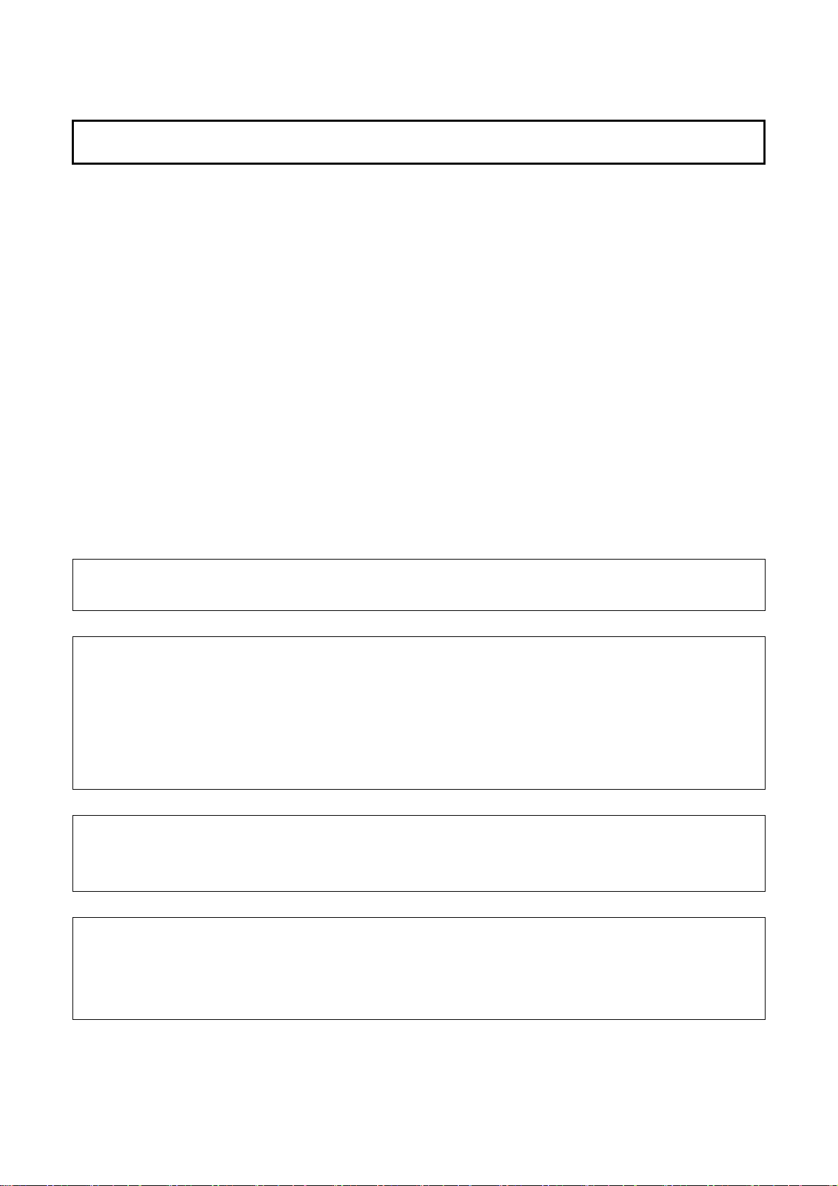
(3) Install a safety fence with a gate so that no user can enter the work area without passing through the
gate. Install an interlocking device, a safety plug, and so forth in the safety gate so that the robot is
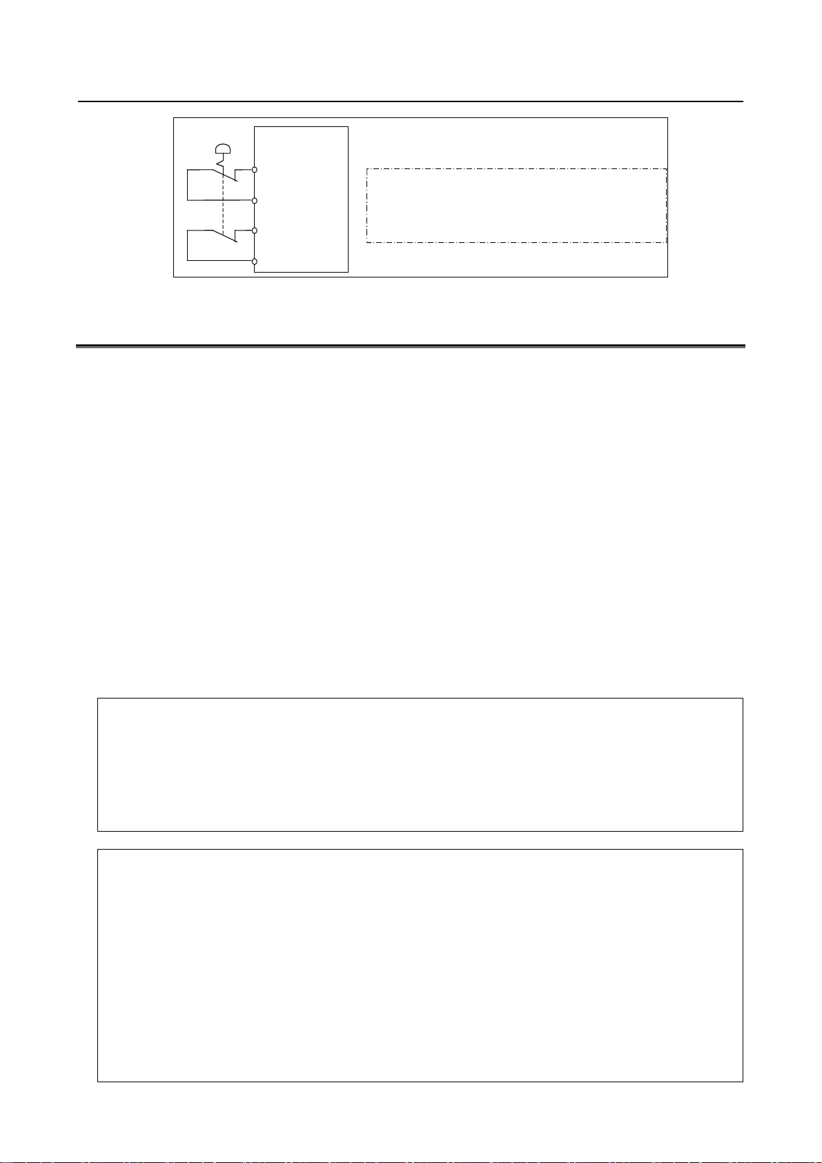
stopped as the safety gate is opened.
The controller is designed to receive this interlocking signal of the door switch. When the gate
is opened and this signal received, the controller stops the robot (Please refer to "STOP
TYPE OF ROBOT" in "SAFETY PRECAUTIONS" for detail of stop type). For connection,
see Fig. 3 (b).
(4) Provide the peripheral equipment with appropriate earth (Class A, Class B, Class C, and Class D).
(5) Try to install the peripheral equipment outside the robot operating space.
(6) Draw an outline on the floor, clearly indicating the range of the robot operating space, including the
tools such as a hand.
(7) Install a mat switch or photoelectric switch on the floor with an interlock to a visual or aural alarm
that stops the robot when a user enters the work area.
(8) If necessary, install a safety lock so that no one except the user in charge can turn on the power of
the robot.
The circuit breaker installed in the controller is designed to disable anyone from turning it on
when it is locked with a padlock.
(9) When adjusting each peripheral equipment independently, be sure to turn off the power of the robot.
(10) Operators should be ungloved while manipulating the operator panel or teach pendant. Operation
with gloved fingers could cause an operation error.
s-2
Page 5
B-83525EN/06 SAFETY PRECAUTIONS
(11) Programs, system variables, and other information can be saved on memory card or USB memories.
Be sure to save the data periodically in case the data is lost in an accident. (refer to Controller
OPERATOR’S MANUAL.)
(12) The robot should be transported and installed by accurately following the procedures recommended
by FANUC. Wrong transportation or installation may cause the robot to fall, resulting in severe
injury to workers.
(13) In the first operation of the robot after installation, the operation should be restricted to low speeds.
Then, the speed should be gradually increased to check the operation of the robot.
(14) Before the robot is started, it should be checked that no one is inside the safety fence. At the same
time, a check must be made to ensure that there is no risk of hazardous situations. If detected, such a
situation should be eliminated before the operation.
(15) When the robot is used, the following precautions should be taken. Otherwise, the robot and
peripheral equipment can be adversely affected, or workers can be severely injured.
- Avoid using the robot in a flammable environment.
- Avoid using the robot in an explosive environment.
- Avoid using the robot in an environment full of radiation.
- Avoid using the robot under water or at high humidity.
- Avoid using the robot to carry a person or animal.
- Avoid using the robot as a stepladder. (Never climb up on or hang from the robot.)
- Outdoor
(16) When connecting the peripheral equipment related to stop (safety fence etc.) and each signal
(external emergency, fence etc.) of robot, be sure to confirm the stop movement and do not take the
wrong connection.
(17) When preparing footstep, please consider security for installation and maintenance work in high
place
according to Fig. 3 (c). Please consider footstep and safety belt mounting position.
RP1
Pulsecoder
RI/RO,XHBK,XROT
RM1
Motor power/brake
EARTH
Interlocking device and safety plug that are activated if the gate is opened.
扉が開いたときに作動するインタロック装置および安全プラグ
Fig. 3 (a) Safety fence and safety gate
s-3
Safety fence
安全柵
Page 6
SAFETY PRECAUTIONS B-83525EN/06
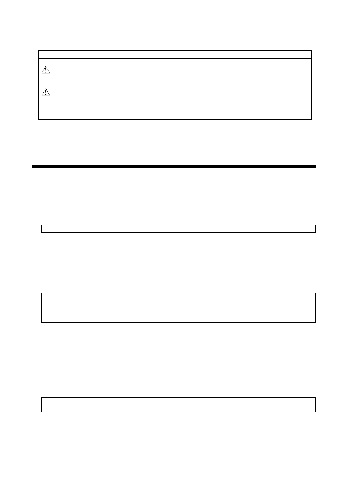
p
Emergency stop board
EAS1
EAS11
EAS2
EAS21
Fig.3 (b) Limit switch circuit diagram of the safety fence
Hook for safety belt
Fence
Steps
(Note)
Connect EAS1 and EAS11, EAS2 and EAS21.
T erminals EAS1,EA11,EAS2,EAS21 are on the emergency sto
board.
Pedestal
for maintenance
Trestle
Fig. 3 (c) Pedestal for maintenance
3.1 SAFETY OF THE OPERATOR
An operator refers to a person who turns on and off the robot system and starts a robot program from, for
example, the operator panel during daily operation.
Operators cannot work inside of the safety fence.
(1) If the robot does not need to be operated, turn off the robot controller power or press the
EMERGENCY STOP button during working.
(2) Operate the robot system outside the operating space of the robot.
(3) Install a safety fence or safety door to avoid the accidental entry of a person other than an operator in
charge or keep operator out from the hazardous place.
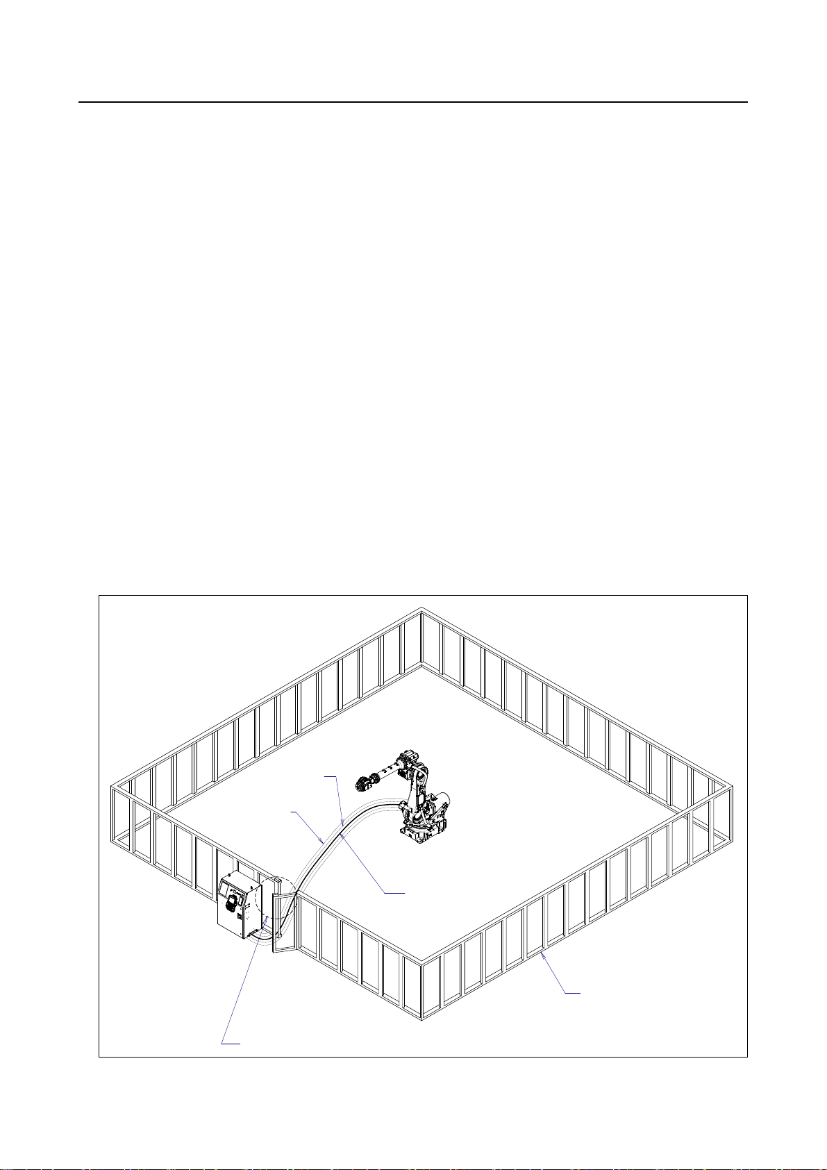
(4) Install one or more necessary quantity of EMERGENCY STOP button(s) within the operator’ s reach
in appropriate location(s) based on the system layout.
The robot controller is designed to be connected to an external EMERGENCY STOP button.
With this connection, the controller stops the robot operation (Please refer to "STOP TYPE
OF ROBOT" in "SAFETY PRECAUTIONS" for detail of stop type) when the external
EMERGENCY STOP button is pressed. See the diagram below for connection.
s-4
Page 7
B-83525EN/06 SAFETY PRECAUTIONS
y
External EMERGENCY
STOP button
Emergency stop board
EES1
EES11
EES2
EES21
Fig. 3.1 Connection diagram for external emergency stop button
(No te )
Connect EES1 and EES11, EES2 and EES21.
Terminals EES1,EES11,EES2,EES21 are on the emergenc
stop board.
3.2 SAFETY OF THE PROGRAMMER
While teaching the robot, the operator must enter the robot operation area. The programmer must ensure
the safety especially.
(1) Unless it is specifically necessary to enter the robot operating space, carry out all tasks outside the
operating space.
(2) Before teaching the robot, check that the robot and its peripheral equipment are all in the normal
operating condition.
(3) If it is inevitable to enter the robot operating space to teach the robot, check the locations, settings,
and other conditions of the safety devices (such as the EMERGENCY STOP button, the
DEADMAN switch on the teach pendant) before entering the area.
(4) The programmer must be extremely careful not to let anyone else enter the robot operating space.
(5) Programming should be done outside the area of the safety fence as far as possible. If programming
needs to be done inside the safety fence, the programmer should take the following precautions:
– Before entering the area of the safety fence, ensure that there is no risk of dangerous situations
in the area.
– Be prepared to press the emergency stop button whenever necessary.
– Robot motions should be made at low speeds.
– Before starting programming, check the whole robot system status to ensure that no remote
instruction to the peripheral equipment or motion would be dangerous to the user.
Our operator panel is provided with an emergency stop button and a key switch (mode switch) for selecting the
automatic operation (AUTO) and the teach modes (T1 and T2). Before entering the inside of the safety fence for
the purpose of teaching, set the switch to a teach mode, remove the key from the mode switch to prevent other
people from changing the operation mode carelessly, then open the safety gate. If the safety gate is opened with
the automatic operation set, the robot stops (Please refer to "STOP TYPE OF ROBOT" in "SAFETY
PRECAUTIONS" for detail of stop type). After the switch is set to a teach mode, the safety gate is disabled. The
programmer should understand that the safety gate is disabled and is responsible for keeping other people from
entering the inside of the safety fence.
Our teach pendant is provided with a DEADMAN switch as well as an emergency stop button. These button and
switch function as follows:
(1) Emergency stop button: Causes the stop of the robot (Please refer to "STOP TYPE OF ROBOT" in
"SAFETY PRECAUTIONS" for detail of stop type) when pressed.
(2) DEADMAN switch: Functions differently depending on the teach pendant enable/disable switch setting
status.
(a) Enable: Servo power is turned off when the operator releases the DEADMAN switch or when the
operator presses the switch strongly.
(b) Disable: The DEADMAN switch is disabled.
(Note) The DEADMAN switch is provided to stop the robot when the operator releases the teach pendant or
presses the pendant strongly in case of emergency. The R-30iB/R-30iB Mate employs a 3-position
DEADMAN switch, which allows the robot to operate when the 3-position DEADMAN switch is pressed
to its intermediate point. When the operator releases the DEADMAN switch or presses the switch
strongly, the robot stops immediately.
s-5
Page 8
SAFETY PRECAUTIONS B-83525EN/06
The operator’s intention of starting teaching is determined by the controller through the dual operation of setting the
teach pendant enable/disable switch to the enable position and pressing the DEADMAN switch. The operator
should make sure that the robot could operate in such conditions and be responsible in carrying out tasks safely.
Based on the risk assessment by FANUC, number of operation of DEADMAN SW should not exceed about 10000
times per year.
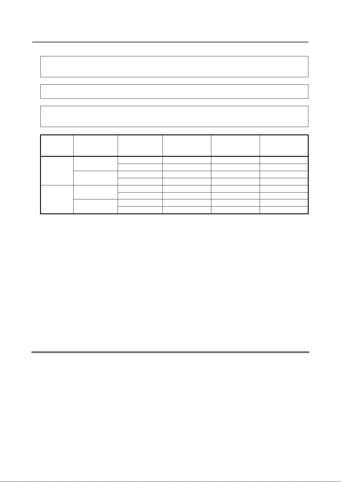
The teach pendant, operator panel, and peripheral equipment interface send each robot start signal. However the
validity of each signal changes as follows depending on the mode switch and the DEADMAN switch of the operator
panel, the teach pendant enable switch and the remote condition on the software.
Mode
AUTO
mode
T1, T2
mode
T1,T2 mode: DEADMAN switch is effective.
Teach pendant
enable switch
On
Off
On
Off
Software
remote
condition
Local Not allowed Not allowed Not allowed
Remote Not allowed Not allowed Not allowed
Local Not allowed Allowed to start Not allowed
Remote Not allowed Not allowed Allowed to start
Local Allowed to start Not allowed Not allowed
Remote Allowed to start Not allowed Not allowed
Local Not allowed Not allowed Not allowed
Remote Not allowed Not allowed Not allowed
Teach pendant Operator panel
(6) To start the system using the operator box or operator panel, make certain that nobody is the robot
operating space area and that there are no abnormalities in the robot operating space.
(7) When a program is completed, be sure to carry out a test operation according to the following
procedure.
(a) Run the program for at least one operation cycle in the single step mode at low speed.
(b) Run the program for at least one operation cycle in continuous operation at low speed.
(c) Run the program for one operation cycle in continuous operation at the intermediate speed and
check that no abnormalities occur due to a delay in timing.
(d) Run the program for one operation cycle in continuous operation at the normal operating speed
and check that the system operates automatically without trouble.
(e) After checking the completeness of the program through the test operation above, execute it in
the automatic operation.
(8) While operating the system in the automatic operation, the programmer should leave the safety
fence.
Peripheral
equipment
3.3 SAFETY OF THE MAINTENANCE ENGINEER
For the safety of maintenance engineer personnel, pay utmost attention to the following.
(1) During operation, never enter the robot operating space.
(2) A hazardous situation may arise when the robot or the system, are kept with their power-on during
maintenance operations. Therefore, for any maintenance operation, the robot and the system should
be put into the power-off state. If necessary, a lock should be in place in order to prevent any other
person from turning on the robot and/or the system. In case maintenance needs to be executed in the
power-on state, the emergency stop button must be pressed.
(3) If it becomes necessary to enter the robot operating space while the power is on, press the emergency
stop button on the operator box or operator panel, or the teach pendant before entering the range.
The maintenance worker must indicate that maintenance work is in progress and be careful not to
allow other people to operate the robot carelessly.
s-6
Page 9

B-83525EN/06 SAFETY PRECAUTIONS
(4) When entering the area enclosed by the safety fence, the worker must check the whole robot system
in order to make sure no dangerous situations exist. In case the worker needs to enter the safety area
whilst a dangerous situation exists, extreme care must be taken, and whole robot system status must
be carefully monitored.
(5) Before the maintenance of the pneumatic system is started, the supply pressure should be shut off
and the pressure in the piping should be reduced to zero.
(6) Before the start of maintenance work, check that the robot and its peripheral equipment are all in the
normal operating condition.
(7) Do not operate the robot in the automatic operation while anybody is in the robot operating space.
(8) When you maintain the robot alongside a wall or instrument, or when multiple users are working
nearby, make certain that their escape path is not obstructed.
(9) When a tool is mounted on the robot, or when any movable device other than the robot is installed,
such as belt conveyor, pay careful attention to its motion.
(10) If necessary, have a user who is familiar with the robot system stand beside the operator panel and
observe the work being performed. If any danger arises, the user should be ready to press the
EMERGENCY STOP button at any time.
(11) When replacing a part, please contact your local FANUC representative. If a wrong procedure is
followed, an accident may occur, causing damage to the robot and injury to the user.
(12) When replacing or reinstalling components, take care to prevent foreign material from entering the
system.
(13) When handling each unit or printed circuit board in the controller during inspection, turn off the
circuit breaker to protect against electric shock.
If there are two cabinets, turn off the both circuit breaker.
(14) A part should be replaced with a part recommended by FANUC. If other parts are used, malfunction
or damage would occur. Especially, a fuse that is not recommended by FANUC should not be used.
Such a fuse may cause a fire.
(15) When restarting the robot system after completing maintenance work, make sure in advance that
there is no person in the operating space and that the robot and the peripheral equipment are not
abnormal.
(16) When a motor or brake is removed, the robot arm should be supported with a crane or other
equipment beforehand so that the arm would not fall during the removal.
(17) Whenever grease is spilled on the floor, it should be removed as quickly as possible to prevent
dangerous falls.
(18) The following parts are heated. If a maintenance user needs to touch such a part in the heated state,
the user should wear heat-resistant gloves or use other protective tools.
- Servo motor
- Inside the controller
- Reducer
- Gearbox
- Wrist unit
(19) Maintenance should be done under suitable light. Care must be taken that the light would not cause
any danger.
(20) When a motor, reducer, or other heavy load is handled, a crane or other equipment should be used to
protect maintenance workers from excessive load. Otherwise, the maintenance workers would be
severely injured.
(21) The robot should not be stepped on or climbed up during maintenance. If it is attempted, the robot
would be adversely affected. In addition, a misstep can cause injury to the worker.
(22) When performing maintenance work in high place, secure a footstep and wear safety belt.
(23) After the maintenance is completed, spilled oil or water and metal chips should be removed from
the floor around the robot and within the safety fence.
(24) When a part is replaced, all bolts and other related components should put back into their original
places. A careful check must be given to ensure that no components are missing or left not mounted.
(25) In case robot motion is required during maintenance, the following precautions should be taken :
s-7
Page 10

SAFETY PRECAUTIONS B-83525EN/06
- Foresee an escape route. And during the maintenance motion itself, monitor continuously the
whole robot system so that your escape route will not become blocked by the robot, or by peripheral
equipment.
- Always pay attention to potentially dangerous situations, and be prepared to press the emergency
stop button whenever necessary.
(26) The robot should be periodically inspected. (Refer to the robot mechanical manual and controller
maintenance manual.) A failure to do the periodical inspection can adversely affect the performance
or service life of the robot and may cause an accident
(27) After a part is replaced, a test execution should be given for the robot according to a predetermined
method. (See TESTING section of “Controller operator’s manual”.) During the test execution, the
maintenance worker should work outside the safety fence.
4 SAFETY OF THE TOOLS AND
PERIPHERAL DEVICES
4.1 PRECAUTIONS IN PROGRAMMING
(1) Use a limit switch or other sensor to detect a dangerous condition and, if necessary, design the
program to stop the robot when the sensor signal is received.
(2) Design the program to stop the robot when an abnormality occurs in any other robots or peripheral
equipment, even though the robot itself is normal.
(3) For a system in which the robot and its peripheral equipment are in synchronous motion, particular
care must be taken in programming so that they do not interfere with each other.
(4) Provide a suitable interface between the robot and its peripheral equipment so that the robot can
detect the states of all devices in the system and can be stopped according to the states.
4.2 PRECAUTIONS FOR MECHANISM
(1) Keep the component cells of the robot system clean, operate the robot where insulated from the
influence of oil, water, and dust.
(2) Don’t use unconfirmed liquid for cutting fluid and cleaning fluid.
(3) Adopt limit switches or mechanical stoppers to limit the robot motion, and avoid the robot from
collisions against peripheral equipment or tools.
(4) Observe the following precautions about the mechanical unit cables. Failure to follow precautions
may cause problems.
• Use mechanical unit cable that have required user interface.
• Do not add user cable or hose to inside of the mechanical unit.
• Please do not obstruct the movement of the mechanical unit when cables are added to outside
of mechanical unit.
• In the case of the model that a cable is exposed, please do not perform remodeling (Adding a
protective cover and fix an outside cable more) obstructing the behavior of the outcrop of the
cable.
• When installing user peripheral equipment on the robot mechanical unit, please pay attention
that the device does not interfere with the robot itself.
(5) The frequent power-off stop for the robot during operation causes the trouble of the robot. Please
avoid the system construction that power-off stop would be operated routinely. (Refer to bad case
example.) Please perform power-off stop after reducing the speed of the robot and stopping it by
hold stop or cycle stop when it is not urgent. (Please refer to "STOP TYPE OF ROBOT" in
"SAFETY PRECAUTIONS" for detail of stop type.)
(Bad case example)
s-8
Page 11

B-83525EN/06 SAFETY PRECAUTIONS
• Whenever poor product is generated, a line stops by emergency stop and power-off of the robot
is incurred.
• When alteration is necessary, safety switch is operated by opening safety fence and power-off
stop is incurred for the robot during operation.
• An operator pushes the emergency stop button frequently, and a line stops.
• An area sensor or a mat switch connected to safety signal operates routinely and power-off stop
is incurred for the robot.
• Power-off stop is regularly incurred due to an inappropriate setting for Dual Check Safety
(DCS).
(6) Power-off stop of Robot is executed when collision detection alarm (SRVO-050) etc. occurs. Please
try to avoid unnecessary power-off stops. It may cause the trouble of the robot, too. So remove the
causes of the alarm.
5 SAFETY OF THE ROBOT MECHANISM
5.1 PRECAUTIONS IN OPERATION
(1) When operating the robot in the jog mode, set it at an appropriate speed so that the operator can
manage the robot in any eventuality.
(2) Before pressing the jog key, be sure you know in advance what motion the robot will perform in the
jog mode.
5.2 PRECAUTIONS IN PROGRAMMING
(1) When the operating spaces of robots overlap, make certain that the motions of the robots do not
interfere with each other.
(2) Be sure to specify the predetermined work origin in a motion program for the robot and program the
motion so that it starts from the origin and terminates at the origin. Make it possible for the operator
to easily distinguish at a glance that the robot motion has terminated.
5.3 PRECAUTIONS FOR MECHANISMS
Keep the robot operation area clean, and operate the robot in an environment free of grease, water, and
dust.
5.4 PROCEDURE TO MOVE ARM WITHOUT DRIVE POWER
IN EMERGENCY OR ABNORMAL SITUATIONS
For emergency or abnormal situations (e.g. persons trapped in or pinched by the robot), brake release unit
can be used to move the robot axes without drive power.
Please refer to controller maintenance manual and mechanical unit operator’s manual for using method of
brake release unit and method of supporting robot.
s-9
Page 12
SAFETY PRECAUTIONS B-83525EN/06
6 SAFETY OF THE END EFFECTOR
6.1 PRECAUTIONS IN PROGRAMMING
(1) To control the pneumatic, hydraulic and electric actuators, carefully consider the necessary time
delay after issuing each control command up to actual motion and ensure safe control.
(2) Provide the end effector with a limit switch, and control the robot system by monitoring the state of
the end effector.
7 STOP TYPE OF ROBOT
The following three robot stop types exist:
Power-Off Stop (Category 0 following IEC 60204-1)
Servo power is turned off and the robot stops immediately. Servo power is turned off when the robot is
moving, and the path of the deceleration is uncontrolled.
The following processing is performed at Power-Off stop.
- An alarm is generated and servo power is turned off.
- The robot operation is stopped immediately. Execution of the program is paused.
Frequent Power-Off stop of the robot during operation can cause failures of the robot.
Avoid system designs that require routine or frequent Power-Off stop conditions.
Controlled stop (Category 1 following IEC 60204-1)
The robot is decelerated until it stops, and servo power is turned off.
The following processing is performed at Controlled stop.
- The alarm "SRVO-199 Controlled stop" occurs along with a decelerated stop. Execution of the
program is paused.
- An alarm is generated and servo power is turned off.
Hold (Category 2 following IEC 60204-1)
The robot is decelerated until it stops, and servo power remains on.
The following processing is performed at Hold.
- The robot operation is decelerated until it stops. Execution of the program is paused.
WARNING
The stopping distance and stopping time of Controlled stop are longer than the
stopping distance and stopping time of Power-Off stop. A risk assessment for
the whole robot system, which takes into consideration the increased stopping
distance and stopping time, is necessary when Controlled stop is used.
When the emergency stop button is pressed or the FENCE is open, the stop type of robot is Power-Off
stop or Controlled stop. The configuration of stop type for each situation is called stop pattern. The stop
pattern is different according to the controller type or option configuration.
s-10
Page 13
B-83525EN/06 SAFETY PRECAUTIONS
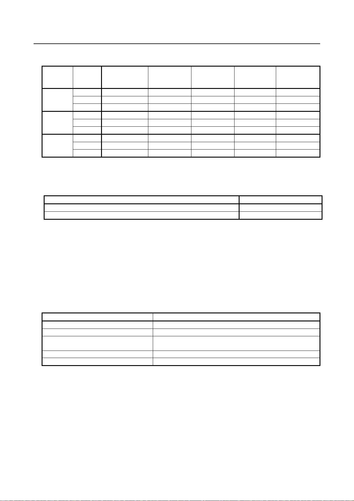
There are the following 3 Stop patterns.
Stop
pattern
AUTO P-Stop P-Stop C-Stop C-Stop P-Stop
A T1 P-Stop P-Stop - C-Stop P-Stop
T2 P-Stop P-Stop - C-Stop P-Stop
AUTO P-Stop P-Stop P-Stop P-Stop P-Stop
B T1 P-Stop P-Stop - P-Stop P-Stop
T2 P-Stop P-Stop - P-Stop P-Stop
AUTO C-Stop C-Stop C-Stop C-Stop C-Stop
C T1 P-Stop P-Stop - C-Stop P-Stop
T2 P-Stop P-Stop - C-Stop P-Stop
Mode
Emergency
stop
button
External
Emergency
stop
FENCE open SVOFF input
Servo
disconnect
P-Stop: Power-Off stop
C-Stop: Controlled stop
-: Disable
The following table indicates the Stop pattern according to the controller type or option configuration.
Option
Standard A (*)
Controlled stop by E-Stop (A05B-2600-J570) C (*)
R-30iB/ R-30iB Mate
(*) R-30iB / R-30iB Mate does not have servo disconnect. / R-30iB Mate does not have SVOFF
input.
The stop pattern of the controller is displayed in "Stop pattern" line in software version screen. Please
refer to "Software version" in operator's manual of controller for the detail of software version screen.
"Controlled stop by E-Stop" option
When "Controlled stop by E-Stop" (A05B-2600-J570) option is specified, the stop type of the following
alarms becomes
Controlled stop but only in AUTO mode. In T1 or T2 mode, the stop type is Power-Off stop which is
the normal operation of the system.
Alarm Condition
SRVO-001 Operator panel E-stop Operator panel emergency stop is pressed.
SRVO-002 Teach pendant E-stop Teach pendant emergency stop is pressed.
SRVO-007 External emergency stops External emergency stop input (EES1-EES11, EES2-EES21) is
open.
SRVO-408 DCS SSO Ext Emergency Stop In DCS Safe I/O connect function, SSO[3] is OFF.
SRVO-409 DCS SSO Servo Disconnect In DCS Safe I/O connect function, SSO[4] is OFF.
Controlled stop is different from Power-Off stop as follows:
- In Controlled stop, the robot is stopped on the program path. This function is effective for a system
where the robot can interfere with other devices if it deviates from the program path.
- In Controlled stop, physical impact is less than Power-Off stop. This function is effective for
systems where the physical impact to the mechanical unit or EOAT (End Of Arm Tool) should be
minimized.
- The stopping distance and stopping time of Controlled stop is longer than the stopping distance and
stopping time of Power-Off stop, depending on the robot model and axis. Please refer to the
operator's manual of a particular robot model for the data of stopping distance and stopping time.
When this option is loaded, this function cannot be disabled.
s-11
Page 14
SAFETY PRECAUTIONS B-83525EN/06
The stop type of DCS Position and Speed Check functions is not affected by the loading of this option.
WARNING
The stopping distance and stopping time of Controlled stop are longer than the
stopping distance and stopping time of Power-Off stop. A risk assessment for
the whole robot system, which takes into consideration the increased stopping
distance and stopping time, is necessary when this option is loaded.
8 WARNING & CAUTION LABEL
(1) Step-on prohibitive label
Fig.8 (a) Step-on prohibitive label
Description
Do not step on or climb the robot or controller as it may adversely affect the robot or controller
and you may get hurt if you lose your footing.
(2) High-temperature warning label
Fig.8 (b) High-Temperature warning label
Description
Be cautious about a section where this label is affixed, as the section generates heat. If y ou
must touch such a section when it is hot, use a protective provision such as heat-resistant
gloves.
s-12
Page 15

B-83525EN/06 SAFETY PRECAUTIONS
(3) High-voltage warning label
Fig.8 (c) High-voltage warning label
Description
A high voltage is applied to the places where this label is attached.
Before starting maintenance, turn the power to the controller off, and turn the circuit breaker
off to avoid electric shock hazards. Take additional precautions with the servo amplifier and
other equipment, because high-voltage remains in these units for a certain amounts of time
s-13
Page 16

Page 17
B-83525EN/06 PREFACE
PREFACE
This manual describes the following models (R-30iB Mate controller).
Model Abbreviation Controller Size
FANUC Robot LR Mate 200iD LR Mate 200iD
FANUC Robot LR Mate 200iD/4S LR Mate 200iD/4S
FANUC Robot LR Mate 200iD/7L LR Mate 200iD/7L
FANUC Robot LR Mate 200iD/7C LR Mate 200iD/7C
FANUC Robot LR Mate 200iD/4SC LR Mate 200iD/4SC
FANUC Robot LR Mate 200iD/7LC LR Mate 200iD/7LC
FANUC Robot LR Mate 200iD/7H LR Mate 200iD/7H
FANUC Robot LR Mate 200iD/4SH LR Mate 200iD/4SH
FANUC Robot LR Mate 200iD/7WP LR Mate 200iD/7WP
FANUC Robot M-1iA/0.5A M-1iA/0.5A
FANUC Robot M-1iA/0.5S M-1iA/0.5S
FANUC Robot M-1iA/1H M-1iA/1H
FANUC Robot M-1iA/0.5AL M-1iA/0.5AL
FANUC Robot M-1iA/0.5SL M-1iA/0.5SL
FANUC Robot M-1iA/1HL M-1iA/1HL
FANUC Robot M-2iA/3S M-2iA/3S
FANUC Robot M-2iA/3SL M-2iA/3SL
FANUC Robot M-2iA/6H M-2iA/6H
FANUC Robot M-2iA/6HL M-2iA/6HL
FANUC Robot M-2iA/3A M-2iA/3A
FANUC Robot M-2iA/3AL M-2iA/3AL
FANUC Robot M-3iA/6A M-3iA/6A
FANUC Robot M-3iA/6S M-3iA/6S
FANUC Robot M-3iA/12H M-3iA/12H
FANUC Robot M-10iA M-10iA
FANUC Robot M-10iA/6L M-10iA/6L
FANUC Robot M-10iA/7L M-10iA/7L
FANUC Robot M-10iA/8L M-10iA/8L
FANUC Robot M-10iA/10S M-10iA/10S
FANUC Robot M-10iA/10M M-10iA/10M
FANUC Robot M-10iA/10MS M-10iA/10MS
FANUC Robot M-10iA/12 M-10iA/12
FANUC Robot M-10iA/12S M-10iA/12S
FANUC Robot M-20iA M-20iA
FANUC Robot M-20iA/10L M-20iA/10L
FANUC Robot M-20iA/12L M-20iA/12L
FANUC Robot M-20iA/20M M-20iA/20M
FANUC Robot M-20iA/35M M-20iA/35M
FANUC Robot M-20iB/25 M-20iB/25 M-20iB
FANUC Robot ARC Mate 50iD ARC Mate 50iD
FANUC Robot ARC Mate 50iD/7L ARC Mate 50iD/7L
LR Mate 200iD
M-1iA
M-2iA
M-3iA
M-10iA
M-20iA
ARC Mate 50iD
Small
Small
Large
Large
Medium
Medium
Medium
Medium or Small
p-1
Page 18
PREFACE B-83525EN/06
Model Abbreviation Controller Size
FANUC Robot ARC Mate 100iC
FANUC ROBOWELD 100iC
FANUC Robot ARC Mate 100iC/6L
FANUC ROBOWELD 100iC/6L
FANUC Robot ARC Mate 100iC/7L ARC Mate 100iC/7L
FANUC Robot ARC Mate 100iC/8L ARC Mate 100iC/8L
FANUC Robot ARC Mate 100iC/10S ARC Mate 100iC/10S
FANUC Robot ARC Mate 100iC/12 ARC Mate 100iC/12
FANUC Robot ARC Mate 100iC/12S ARC Mate 100iC/12S
FANUC Robot ARC Mate 120iC
FANUC ROBOWELD 120iC
FANUC Robot ARC Mate 120iC/10L
FANUC ROBOWELD 120iC/10L
FANUC Robot ARC Mate 120iC/12L ARC Mate 120iC/12L
FANUC Robot ARC Mate 0iB ARC Mate 0iB ARC Mate 0iB
FANUC Robot R-0iB R-0iB R-0iB
FANUC Robot R-2000iC/125L R-2000iC/125L
FANUC Robot R-2000iC/165F R-2000iC/165F
FANUC Robot R-2000iC/165R R-2000iC/165R
FANUC Robot R-2000iC/210F R-2000iC/210F
FANUC Robot R-2000iC/210R R-2000iC/210R
FANUC Robot R-1000iA/80F R-1000iA/80F
FANUC Robot R-1000iA/100F R-1000iA/100F
FANUC Robot M-710iC/70 M-710iC/70
FANUC Robot M-710iC/70T M-710iC/70T
FANUC Robot M-710iC/50 M-710iC/50
FANUC Robot M-710iC/50S M-710iC/50S
FANUC Robot M-710iC/50T M-710iC/50T
FANUC Robot M-710iC/50E M-710iC/50E
FANUC Robot M-710iC/45M M-710iC/45M
FANUC Robot M-710iC/20L M-710iC/20L
FANUC Robot M-710iC/20M M-710iC/20M
FANUC Robot M-710iC/12L M-710iC/12L
Explanation of Controller size
Controller size
Small 400X470X322 Small 10A Single phase/Three phase
Medium 400X470X402 Large 20A Three phase
Large 400X470X402 Large 30A Three phase
Dimension
(Height X Width X Depth)
ARC Mate 100iC
ARC Mate 100iC/6L
ARC Mate 120iC
ARC Mate 120iC/10L
Discharge
resistor
ARC Mate 100iC
ARC Mate 120iC
R-2000iC
R-1000iA
M-710iC
Breaker
capacity
Medium
Medium
Medium
Medium
Large
Large
Large
Single phase/Three phase
p-2
Page 19

B-83525EN/06 TABLE OF CONTENTS
TABLE OF CONTENTS
SAFETY PRECAUTIONS............................................................................s-1
PREFACE....................................................................................................p-1
I. MAINTENANCE
1 OVERVIEW .............................................................................................3
2 CONFIGURATION .................................................................................. 4
2.1 EXTERNAL VIEW OF THE CONTROLLER .................................................. 4
2.2 COMPONENT FUNCTIONS.......................................................................... 8
2.3 CHECKS AND MAINTENANCE .................................................................... 9
3 TROUBLESHOOTING .......................................................................... 11
3.1 POWER CANNOT BE TURNED ON ........................................................... 11
3.1.1 When the Teach Pendant Cannot be Powered on...................................................11
3.1.2 When the Teach Pendant does not Change from the Initial Screen .......................12
3.2 ALARM OCCURRENCE SCREEN.............................................................. 13
3.3 STOP SIGNALS ..........................................................................................15
3.4 MASTERING ...............................................................................................16
3.5 TROUBLESHOOTING USING THE ALARM CODE.................................... 18
3.6 FUSE-BASED TROUBLESHOOTING......................................................... 63
3.7 TROUBLESHOOTING BASED ON LED INDICATIONS ............................. 67
3.7.1 Troubleshooting Using the LEDS On the Main Board ..........................................67
3.7.2 Troubleshooting by LEDs on the 6-Axis Servo Amplifier ....................................71
3.7.3 Troubleshooting by LED on the Emergency Stop Board.......................................72
3.7.4 Troubleshooting by Alarm LEDs on the Process I/O Board ..................................74
3.8 MANUAL OPERATION IMPOSSIBLE ......................................................... 74
3.9 LEDS ON UNITS SUPPORTING I/O LINK i ................................................ 75
3.9.1 Meanings of LEDs on Units Supporting I/O Link i ...............................................75
4 PRINTED CIRCUIT BOARDS...............................................................77
4.1 MAIN BOARD.............................................................................................. 77
4.2 EMERGENCY STOP BOARD (A20B-2005-0150)....................................... 80
4.3 BACKPLANE ............................................................................................... 80
4.4 PROCESS I/O BOARD MA (A20B-2004-0381)........................................... 81
4.5 PROCESS I/O BOARD MB (A20B-2101-0731)........................................... 82
4.6 CONNECTOR CONVERTER BOARD (A20B-2004-0411) .......................... 83
4.7 TERMINAL CONVERTER BOARD (A20B-1009-0690) ............................... 83
5 6-AXIS SERVO AMPLIFIERS............................................................... 84
5.1 LEDS OF 6-AXIS SERVO AMPLIFIER........................................................ 85
5.2 SETTING OF 6-AXIS SERVO AMPLIFIER ................................................. 86
5.3 6-AXIS SERVO AMPLIFIER SPECIFICATIONS ......................................... 87
6 POWER SUPPLY ..................................................................................88
6.1 BLOCK DIAGRAM OF THE POWER SUPPLY ........................................... 88
c - 1
Page 20

TABLE OF CONTENTS B-83525EN/06
7 REPLACING UNITS.............................................................................. 89
7.1 REPLACING THE PRINTED-CIRCUIT BOARDS ....................................... 89
7.1.1 Replacing the Backplane Board (Unit)...................................................................90
7.1.2 Replacing the Main Board......................................................................................91
7.2 REPLACING CARDS AND MODULES ON THE MAIN BOARD ................. 91
7.3 REPLACING THE EMERGENCY STOP UNIT............................................ 96
7.4 REPLACING THE EMERGENCY STOP BOARD ....................................... 96
7.5 REPLACING THE POWER SUPPLY UNIT................................................. 97
7.6 REPLACING THE REGENERATIVE RESISTOR UNIT .............................. 98
7.7 REPLACING THE 6-AXIS SERVO AMPLIFIER .......................................... 99
7.8 REPLACING THE TEACH PENDANT....................................................... 101
7.9 REPLACING THE CONTROL SECTION FAN MOTOR............................ 102
7.10 REPLACING THE AC FAN MOTOR ......................................................... 103
7.10.1 Replacing the Heat Exchanger and Door Fan Unit ..............................................103
7.11 REPLACING THE BATTERY .................................................................... 104
7.11.1 Battery for Memory Backup (3 VDC)..................................................................104
II. CONNECTIONS
1 OVERVIEW .........................................................................................109
2 BLOCK DIAGRAM ..............................................................................110
3 ELECTRICAL CONNECTIONS...........................................................111
3.1 CONNECTION DIAGRAM BETWEEN MECHANICAL UNITS .................. 111
3.2 CONNECTION TO FANUC I/O Link and FANUC I/O Link i ...................... 113
3.2.1 Connection of I/O Link and I/O Link i by Using JRS26 Connector ....................113
3.2.1.1 Connection of the I/O Link cable by using JRS26 connector.......................... 114
3.2.1.2 Cable connection diagram of the I/O Link cable by using JRS26 connector .. 115
3.2.2 Connection of JD44A Connector(Option)............................................................116
3.2.2.1 Connection of the I/O Link cable by using JD44A connector......................... 116
3.2.2.2 Cable connection diagram of the I/O Link cable by using JD44A connector . 117
3.3 EXTERNAL CABLE WIRING DIAGRAM................................................... 117
3.3.1 Robot Connection Cables .....................................................................................117
3.3.2 Teach Pendant Cable ............................................................................................120
3.3.3 Connecting the Input Power .................................................................................120
3.3.3.1 Connecting the input power cable ................................................................... 120
3.3.3.2 Isolated transformer......................................................................................... 121
3.3.3.3 Leakage breaker............................................................................................... 122
3.3.4 Connecting the External Emergency Stop............................................................123
3.3.5 Connecting the Auxiliary Axis Brake (CRR65 A/B) ...........................................129
3.3.6 Connecting the Auxiliary Axis Over Travel (CRM68) ........................................130
4 PERIPHERAL DEVICE, ARC WELDING, AND EE INTERFACES ....131
4.1 PERIPHERAL DEVICE INTERFACE BLOCK DIAGRAM.......................... 133
4.1.1 In Case of Main Board (CRMA15, CRMA16) ....................................................133
4.1.2 In the Case of the Process I/O Board MA ............................................................133
4.1.3 In the Case of the Process I/O Board MB ............................................................134
4.1.4 In the Case of the Connector Conversion Board ..................................................134
4.1.5 In the Case of the Terminal Converter Board.......................................................135
4.2 I/O SIGNALS OF MAIN BOARD................................................................ 136
c - 2
Page 21

B-83525EN/06 TABLE OF CONTENTS
4.3 INTERFACE FOR PERIPHERAL DEVICES.............................................. 138
4.3.1 Connection between the Main Board (CRMA15, CRMA16) and
Peripheral Devices................................................................................................138
4.3.2 Connection between the Connector Converter Board and Peripheral Devices ....144
4.3.3 Connection between the Terminal Converter Board and Peripheral Devices ......145
4.3.4 Connection between the Process I/O Board MA and Peripheral Devices ............146
4.4 INTERFACE FOR WELDING MACHINES ................................................ 150
4.4.1 Connection between the Process I/O Board MB and Welding Machines ............150
4.5 EE INTERFACE......................................................................................... 152
4.5.1 Connection between the Robot and End Effector ................................................152
4.6 DIGITAL I/O SIGNAL SPECIFICATIONS.................................................. 155
4.6.1 Peripheral Device Interface A ..............................................................................155
4.6.2 EE Interface ..........................................................................................................157
4.6.3 I/O Signal Specifications for ARC-Welding Interface
(A-cabinet/Process I/O Board MB) ......................................................................158
4.7 SPECIFICATIONS OF THE CABLES USED FOR
PERIPHERAL DEVICES AND WELDERS ................................................ 161
4.7.1 Peripheral Device Interface A1 Cable
(CRMA15: Tyco Electronics AMP, 40 pins) .......................................................161
4.7.2 Peripheral Device Interface A2 Cable
(CRMA16: Tyco Electronics AMP, 40 pins) .......................................................161
4.7.3 Peripheral Device Interface B1 and B2 Cables
(CRMA52; Tyco Electronics AMP, 30 pin).........................................................162
4.7.4 ARC Weld Connection Cables
(CRW11; Tyco Electronics AMP, 20 pin) ...........................................................162
4.8 CABLE CONNECTION FOR THE PERIPHERAL DEVICES, END
EFFECTORS, AND ARC WELDERS ........................................................ 163
4.8.1 Peripheral Device Connection Cable....................................................................163
4.8.2 Peripheral Device Cable Connector .....................................................................164
4.8.3 Recommended Cables ..........................................................................................166
4.9 CONNECTION OF HDI ............................................................................. 167
4.9.1 Connecting HDI ...................................................................................................167
4.9.2 Input Signal Rules for the High-speed Skip (HDI) ..............................................168
4.10 CONNECTING THE COMMUNICATION UNIT ......................................... 169
4.10.1 RS232C Interface .................................................................................................169
4.10.1.1 Interface ........................................................................................................... 169
4.10.1.2 RS232C interface signals................................................................................. 170
4.10.1.3 Connection between RS232C interface and I/O device................................... 170
4.10.2 Ethernet Interface .................................................................................................172
4.10.2.1 Connection to Ethernet ....................................................................................172
4.10.2.2 Routing of the Ethernet cable ..........................................................................173
4.10.2.3 100BASE-TX connector (CD38A, CD38B) pin assignments......................... 173
4.10.2.4 Twisted-pair cable specification...................................................................... 174
4.10.2.5 Electrical noise countermeasures..................................................................... 177
4.10.2.6 Check items at installation............................................................................... 180
5 TRANSPORTATION AND INSTALLATION ....................................... 181
5.1 TRANSPORTATION.................................................................................. 181
5.2 INSTALLATION ......................................................................................... 182
5.2.1 Installation Method...............................................................................................182
5.2.2 Assemble at Installation .......................................................................................184
5.3 INSTALLATION OF TEACH PENDANT HOOK (OPTION) ....................... 185
5.4 INSTALLATION CONDITION .................................................................... 186
c - 3
Page 22

TABLE OF CONTENTS B-83525EN/06
5.5 ADJUSTMENT AND CHECKS AT INSTALLATION .................................. 189
5.6 RESETTING OVERTRAVEL AND EMERGENCY STOP
AT INSTALLATION.................................................................................... 189
5.6.1 Peripheral Device Interface Processing ................................................................189
5.6.2 Resetting Overtravel .............................................................................................190
5.6.3 How to Disable/Enable HBK ...............................................................................190
5.6.4 How to Disable/Enable Pneumatic Pressure Alarm (PPABN).............................190
APPENDIX
A SPECIFICATION LIST ........................................................................ 193
B TOTAL CONNECTION DIAGRAM......................................................196
C SPECIFICATIONS OF PERIPHERAL DEVICE INTERFACE............. 220
C.1 SIGNAL .....................................................................................................220
C.2 SETTING COMMON VOLTAGE................................................................ 222
C.3 I/O SIGNALS ............................................................................................. 222
C.3.1 Input Signals.........................................................................................................222
C.3.2 Output Signals ......................................................................................................225
C.4 SPECIFICATIONS OF DIGITAL INPUT/OUTPUT.....................................228
C.4.1 Overview ..............................................................................................................228
C.4.2 Input/Output Hardware Usable in the R-30iB Mate Controller ...........................228
C.4.3 Software Specifications ........................................................................................229
D OPTICAL FIBER CABLE....................................................................230
E BRAKE RELEASE UNIT.....................................................................233
E.1 SAFETY PRECAUTIONS..........................................................................233
E.2 CONFIRMATIONS BEFORE OPERATION............................................... 233
E.3 OPERATION.............................................................................................. 234
E.3.1 In Case of Operating to the Robot........................................................................234
E.3.2 In Case of Operating to the Auxiliary Axis..........................................................236
E.4 HOW TO CONNECT THE PLUG TO THE POWER CABLE
(IN CASE OF NO POWER PLUG) ............................................................237
E.5 DIMENSION .............................................................................................. 238
E.6 FUSE ......................................................................................................... 239
E.7 SPECIFICATIONS..................................................................................... 240
F TEACH PENDANT DISCONNECT FUNCTION (OPTION).................241
F.1 CONFIGURATION..................................................................................... 241
F.2 PROCEDURE OF TEACH PENDANT DISCONNECT .............................. 241
F.2.1 Teach Pendant Disconnect ...................................................................................241
F.2.2 Teach Pendant Connect ........................................................................................242
G INSTRUCTION FOR TERMINAL BLOCK .......................................... 243
G.1 EXTERNAL EMERGENCY STOP SIGNAL INPUT/OUTPUT
TERMINAL BLOCK ...................................................................................243
G.2 TERMINAL CONVERTER BOARD TERMINAL BLOCK ........................... 245
H REPLACING THE PROTECTION SHEET .......................................... 246
c - 4
Page 23

B-83525EN/06 TABLE OF CONTENTS
I SEALING OF THE CABLE ENTRANCE OF THE CABINET .............247
I.1 CABLE ENTRANCE FOR Mate-CABINET ................................................ 247
I.2 HOLES OF CABLE SEAL BLOCK FOR CABLE ENTRANCE................... 248
I.3 SUITABLE CABLE DIAMETER ................................................................. 249
I.4 ADJUST THE CABLE DIAMETER ............................................................ 250
c - 5
Page 24

Page 25

I. MAINTENANCE
Page 26

Page 27
B-83525EN/06 MAINTENANCE 1. OVERVIEW
1 OVERVIEW
This manual is applied to R-30iB Mate controller (called R-30iB Mate).
R-30iB Mate has three variations depending on the required standards.
Basic controller : To meet Safety Standard and General electrical requirement
CE controller : To meet Machinery Directive, Low voltage Directive, EMC Directive to cover the
requirement of CE mark
NRTL controller : To meet UL/CSA standard
This manual covers these three variations of R-30iB Mate.
The difference of NRTL and CE controller from Basic controller is small as shown in Table 1 (ex. EMC
parts, Breakers).
And the specific descriptions of CE and NRTL controller have notifications in this manual.
Table 1. Applied standards
Basic
controller
CE
controller
NRTL
controller
Common
Standard
ISO 10218-1
ISO 13849-1
IEC 60204-1
IEC 61508
This manual describes the maintenance and connection of R-30iB Mate.
・Maintenance Part: Troubleshooting, and the setting, adjustment, and replacement of units
・Connection Part: Connection of R-30iB Mate to the robot mechanical unit and peripheral devices,
and installation of the controller
WARNING
Before you enter the robot working area, be sure to turn off the power to the
controller or press the EMERGENCY STOP button on the operator's panel or
teach pendant.
Otherwise, you could injure personnel or damage equipment.
EMC
Standard
- -
EN 55011
EN 61000-6-2
EN 61000-6-4
-
UL/CSA
Standard
-
UL1740
CAN/CSA Z434
NFPA79
Requirement Difference
Safety Standard
General electrical
requirement
CE Marking
•Europe
UL standard
CSA standard
•USA and Canada
•Noise filter
•EMC Cabinet
•Shielded cable
•UL listed main breaker
-
- 3 -
Page 28
2. CONFIGURATION MAINTENANCE B-83525EN/06
2 CONFIGURATION
2.1 EXTERNAL VIEW OF THE CONTROLLER
The appearance and components might slightly differ depending on the controlled robot, application, and
options used.
Fig.2.1 (a) shows the view of R-30iB Mate.
Fig.2.1 (b) to (d) show the construction of the R-30iB Mate controller.
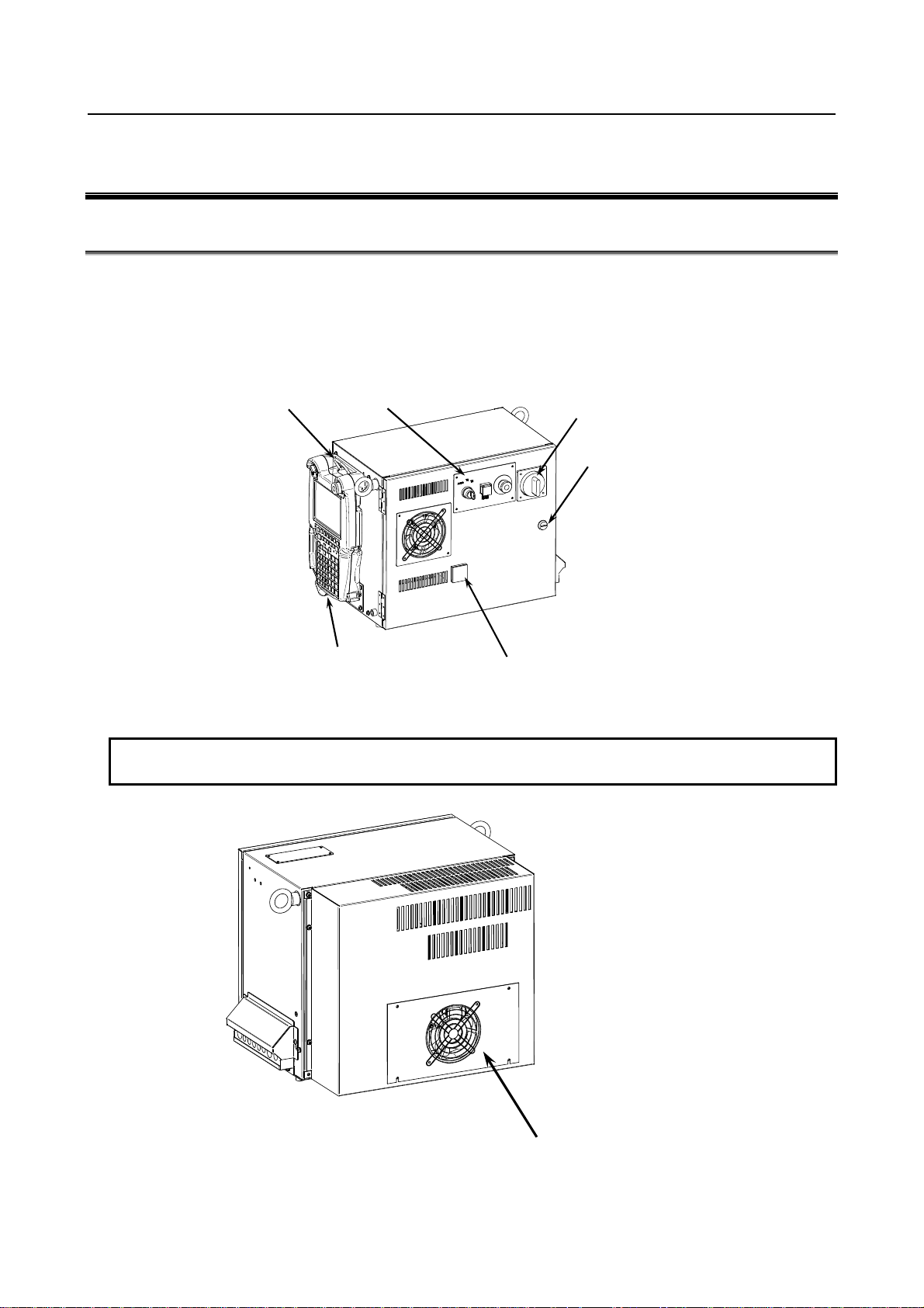
Fig.2.1 (e) to (g) show the external view of the operator’s panel and teach pendant.
Teach pendant hook
(Option)
Operator’s panel
Breaker
Key
Teach pendant
(iPendant)
Fig.2.1 (aa) External view of the R-30iB Mate controller
NOTE
Be sure to lock the key.
USB port (Option)
Rear fan unit
Fig.2.1 (ab) External view of the R-30iB Mate controller (Middle/Large size) (Rear)
- 4 -
Page 29
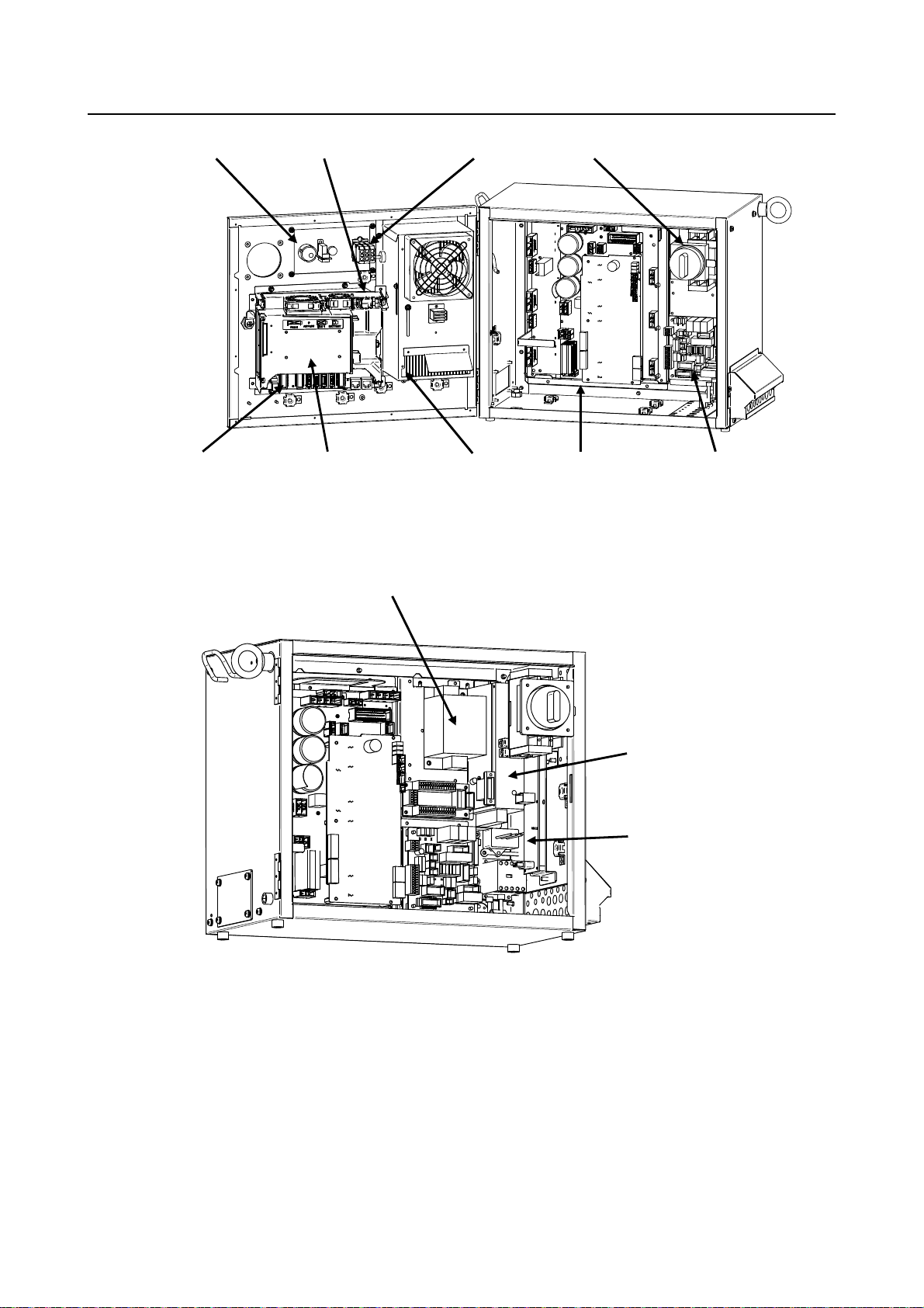
B-83525EN/06 MAINTENANCE 2. CONFIGURATION
Emergency stop button
Main board
Battery
Back plane unit
mode switch
Heat exchanger 6-Axis Servo amplifier
Fig.2.1 (b) R-30iB Mate cabinet interior (Front-1)
Noise Filter
(EMC Option)
Breaker
E-stop unit
Fig.2.1 (c) R-30iB Mate cabinet interior (Front-2)
Power supply unit
Process I/O board
(Option)
- 5 -
Page 30
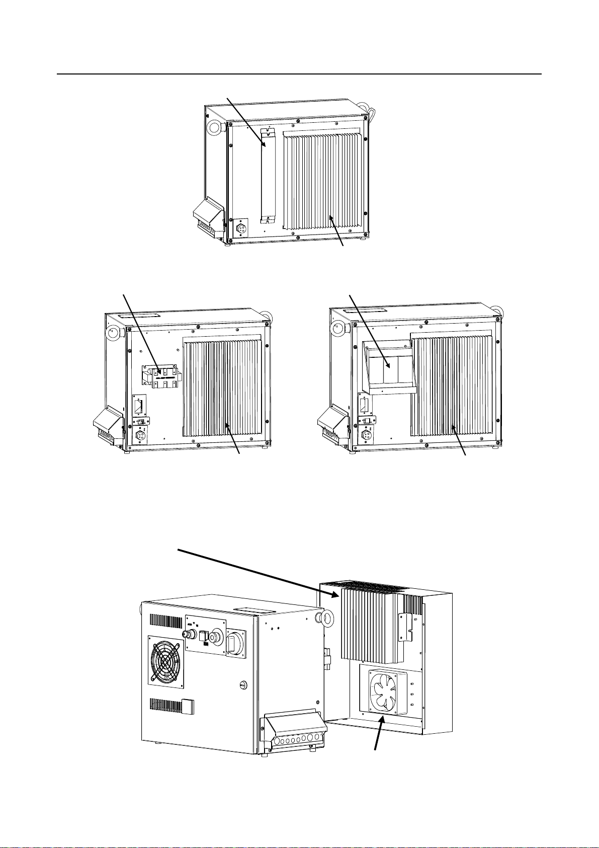
2. CONFIGURATION MAINTENANCE B-83525EN/06
Line filter
Regenerative resistor
(Small size)
6-Axis Servo amplifier (Rear side)
Line filter
6-Axis Servo amplifier (Rear side)
(Middle size) (Large size)
Fig.2.1 (da) R-30iB Mate cabinet interior (Rear)
Regenerative resistor
6-Axis Servo amplifier (Rear side)
Rear fan unit
Fig.2.1 (db) R-30iB Mate cabinet interior (Middle/Large size) (Rear)
- 6 -
Page 31

B-83525EN/06 MAINTENANCE 2. CONFIGURATION
NOTE
The number of fans on the fan unit (0,1,2) will vary depending on the robot type.
Mode switch
(In case of 3-mode switch)
Emergency Stop button
Enable/disable switch
CYCLE START button with LED(Green)
Fig.2.1 (e) R-30iB Mate operator’s panel
2 mo de sw itch 3 mode swit ch
Fig.2.1 (f) Mode switch
Emergency Stop button
USB port
Fig.2.1 (g) Teach pendant (iPendant)
- 7 -
Deadman sw it ch
Page 32

2. CONFIGURATION MAINTENANCE B-83525EN/06
2.2 COMPONENT FUNCTIONS
Fig.2.2 Block diagram of the R-30iB Mate
- 8 -
Page 33

B-83525EN/06 MAINTENANCE 2. CONFIGURATION
- Main board
The main board contains a microprocessor, its peripheral circuits, memory, and operator's panel
control circuit. The main CPU controls servo mechanism positioning.
- I/O printed circuit board
Various ty pes of printed circuit boards are provided for applications including process I/O board.
These are connected with FANUC I/O Link.
- E-stop unit
This unit controls the emergency stop system of the robot controller. It also has user interface
terminals of safety relevant signals, external on/off signals etc.
- Power supply unit
The power supply unit converts the AC power to various levels of DC power.
- Backplane printed circuit board
The various control printed circuit boards are mounted on the backplane printed circuit board.
- Teach pendant
All operations including robot programming are performed with this unit. The controller status and
data are indicated on the liquid-crystal display (LCD) on the pendant.
- 6-Axis Servo amplifier
The servo amplifier controls servomotor, Pulsecoder signal, brake control, overtravel and hand
broken.
- Operator's panel
Buttons and LEDs on the operator's panel are used to start the robot and to indicate the robot status.
- Fan unit, heat exchanger
These components cool the inside of the controller.
- Circuit breaker
If the electric system in the controller malfunctions, or if abnormal input power causes high current
in the system, the input power is connected to the circuit breaker to protect the equipment.
- Regenerative resistor
To discharge the counter electromotive force from the servomotor, connect a regenerative resistor to
the servo amplifier.
2.3 CHECKS AND MAINTENANCE
Daily maintenance and periodic maintenance/inspection ensure reliable robot performance for extended
periods of time.
(1) Daily maintenance
Before operating the system each day, clean each part of the system and check the system parts for
any damage or cracks. Also, check the following:
(a) Before operation
Check the cable connected to the teach pendant for excessive twisting. Check the controller
and peripheral devices for abnormalities.
(b) After operation
At the end of operation, return the robot to the specified position, and then turn off the
controller. Clean each part, and check for any damage or cracks. If the ventilation port of
the controller is dusty, clean it.
(2) Check after one month
Check that the fan is rotating normally. If the fan has dirt and dust built up, clean the fan according
to step (3) described below for inspection to be performed every 6 months.
(3) Periodic inspection performed every six months
Remove any dirt and dust from the inside of the cabinet. Wipe off dirt and dust from the fan.
(4) Battery daily check
Replace the battery on the front panel of the main board every 4 years. Please refer to the Section
7.11.
(5) Maintenance tools
- 9 -
Page 34

2. CONFIGURATION MAINTENANCE B-83525EN/06
The following maintenance tools are recommended:
(a) Measuring instruments
AC/DC voltmeter (A digital voltmeter is sometimes required.)
Oscilloscope with a frequency range of 5 MHz or higher, two channels
(b) Tools
Cross-head screwdrivers: Large, medium, and small
Straight-head screwdrivers: Large, medium, and small
Nut driver set (Metric)
Pliers
Needle-nose pliers
Diagonal cutting pliers
- 10 -
Page 35

B-83525EN/06 MAINTENANCE 3. TROUBLESHOOTING
3 TROUBLESHOOTING
This chapter describes the checking method and corrective action for each alarm code indicated if a
hardware alarm occurs. Refer to the R-30iB/R-30iB Mate OPERATOR’S MANUAL (ALARM CODE
LIST) (B-83284EN-1) to release program alarms.
3.1 POWER CANNOT BE TURNED ON
Check and Corrective action Figure
(Check 1) Check that the circuit
breaker is on and has not
tripped.
(Corrective
action)
a) If circuit breaker is OFF.
Turn on the circuit
breaker.
b) If the circuit breaker has
tripped, find the cause
by referencing the total
connection diagram
presented in the
appendix.
Circuit Breaker
3.1.1 When the Teach Pendant Cannot be Powered on
Inspection and action Illustration
(Inspection 1) Confirm that fuse (FUSE3) on the
emergency stop board is not
blown. When it is blown, the
LED on the emergency stop board
lights in red. When fuse
(FUSE3) is blown, carry out action
1 and replace the fuse.
(Inspection 2) When fuse (FUSE3) is not blown,
carry out action 2.
(Action 1) (a) Check the cable of the teach
pendant for failure and replace it as
necessary.
(b) Check the teach pendant for
failure and replace it as necessary.
(c) Replace the emergency stop
board.
(Action 2) When the LED on the main board
does not light, replace the
emergency stop unit. When the
LED on the main board lights, carry
out action 1.
Teach pendant
FUSE3
LED
(Red)
- 11 -
Page 36

3. TROUBLESHOOTING MAINTENANCE B-83525EN/06
3.1.2 When the Teach Pendant does not Change from the Initial
Screen
Inspection and action Illustration
(Inspection 1)
Check that the status display LED and
7-segment LED on the main board
operate normally.
(Action) Carry out an action according to the
LED status. For details, see
"TROUBLESHOOTING USING THE
LEDS ON THE MAIN BOARD".
7 Segment LED
(Inspection 2)
When the LED on the main board
does not light in inspection 1, check
if fuse (FUSE1) on the main board is
blown.
(a) When fuse (FUSE1) is blown
See action 1.
(b) When fuse (FUSE1) is not blown
See action 2.
(Action 1) (a) Replace the backplane board.
(b) Replace the main board.
(c) When an option board is installed
in the mini slot, replace the option
board.
(Action 2) (a) Replace the emergency stop
unit.
(b) Replace the cable between the
main board and the emergency stop
unit.
(c) Replace the boards indicated in
action 1.
Back plane
RLED1
LEDG1
LEDG2
LEDG3
LEDG4
(Red)
(Green)
FUSE1
Mini slot (2slot)
- 12 -
Page 37

B-83525EN/06 MAINTENANCE 3. TROUBLESHOOTING
A
A
A
A
d
M
A
3.2 ALARM OCCURRENCE SCREEN
The alarm occurrence screen displays only the alarm conditions that are currently active. If an alarm reset
signal is input to reset the alarm conditions, the alarm occurrence screen displays the message "PAUSE or
more serious alarm has not occurred."
The alarm occurrence screen displays only the alarm conditions (if any) that occur after the most recently
entered alarm reset signal. To erase all alarm displays from the alarm occurrence screen. Press the
CLEAR key (+ shift) on the alarm history screen.
The alarm occurrence screen is intended to display PAUSE or alarms that are more serious. It will not
display WARN, NONE, or a reset. It is possible to disable PAUSE and some of more serious alarms from
being displayed by setting the $ER_NOHIS system variable appropriately.
If two or more alarms have occurred, the display begins with the most recent alarm.
Up to 100 lines can be displayed.
If an alarm has a cause code, it is displayed below the line indicating the alarm.
Press the screen
selection key to select
[4 ALARM].
larm occurrence screen display
Press F3 [HIST]. Press F3 [ACTIVE].
larm history screen display
Fig.3.2 Alarm occurrence screen and alarm history screen display procedure
utomatic alarm display
upon occurrence
Displaying the alarm active/ alarm history/alarm detail information
Step
(1) Press the [MENU] key to display the screen menu.
(2) Select [ALARM].
You will see a screen similar to the following.
If an alarm has occurred, however, the alarm screen appears automatically.
larm : Active
1/2
1 INTP-224 (TEST1, 6) Jump label faile
MEMO-027 Specified line does not exi
[ TYPE ] [ VIEW ] HIST RES_1CH
INTP-224 (TEST1, 6)Jump label faile
EMO-027 Specified line does not exis JOINT
- 13 -
30%
larm detail code
Page 38

3. TROUBLESHOOTING MAINTENANCE B-83525EN/06
(3) To display the alarm history screen, press F3, [HIST].
Press F3 [ACTIVE] again, the alarm screen appears.
Alarm : Hist
1/25
1 INTP-224 (TEST1, 6) Jump label faile
2 R E S E T
3 SRVO-007 External emergency stop
4 SRVO-001 Operator panel E-stop
5 R E S E T
6 SRVO-001 Operator panel E-stop
7 SRVO-012 Power failure recovery
8 INTP-127 Power fail detected
9 SRVO-047 LVAL alarm (Group:1 Axis:5)
10 SRVO-047 LVAL alarm (Group:1 Axis:4)
11 SRVO-002 Teach pendant E-stop
[ TYPE ] [ VIEW ] ACTIVE CLEAR DETAIL
NOTE
The latest alarm is assigned number 1. To view messages that are currently
not on the screen, press the F5, HELP, and then press the right arrow key.
(4) To display the alarm detail screen, press F5, [HELP].
Alarm : Hist
DETAIL Alarm
INTP-224 (TEST1, 6) Jump label failed
MEMO-027 Specified line does not exist
STOP.L 21-NOV-11 12:16
Alarm : Hist
1 INTP-224 (TEST1, 6) Jump label faile
2 R E S E T
3 SRVO-007 External emergency stop
4 SRVO-001 Operator panel E-stop
5 R E S E T
6 SRVO-001 Operator panel E-stop
7 SRVO-012 Power failure recovery
[ TYPE ] [ VIEW ] ACTIVE CLEAR DETAIL
(5) To return to the alarm history screen, press the PREV key.
(6) To delete all the alarm histories, press and hold down the SHIFT key, then press F4, [CLEAR].
NOTE
When system variable $ER_NOHIS = 1, NONE alarms or WARN alarms are not
recorded. When $ER_NOHIS=2, resets are not recorded in the alarm history.
When $ER_NOHIS=3, resets, WARN alarms, and NONE alarms are not
recorded.
- 14 -
Page 39

B-83525EN/06 MAINTENANCE 3. TROUBLESHOOTING
The following map indicates teach pendant operations used to check an alarm.
4 ALARM
F1 [TYPE]
Alarm : Active
F1 [TYPE]
F3 HIST
Alarm : HIST
F1 [TYPE]
F3 [ACTIVE]
F4 CLEAR
F5 HELP
DETAIL Alarm
F1 [TYPE]
F3 [ACTIVE]
F4 CLEAR
F5 HELP
3.3 STOP SIGNALS
The stop signal screen indicates the state of signals related to stop.
To be specific, the screen indicates whether each stop signal is currently on. On this screen, it is
impossible to change the state of any stop signal.
Table 3.3 Stop signals
Stop signal Description
Operator’s panel
emergency stop
Teach pendant
emergency stop
External emergency stop This item indicates the state of the external emergency stop signal. If the
Fence open This item indicates the state of the safety fence. If the safety fence is open, the state is
DEADMAN switch This item indicates whether the DEADMAN switch on the teach pendant is grasped. If
Teach pendant operable This item indicates whether the teach pendant is operable. If the teach pendant is
Hand broken This item indicates the state of the hand safety joint. If the hand interferes with a
This item indicates the state of the emergency stop button on the operator’s panel. If
the EMERGENCY STOP button is pressed, the state is indicated as “TRUE”.
This item indicates the state of the emergency stop button on the teach pendant. If the
EMERGENCY STOP button is pressed, the state is indicated as “TRUE”.
EMERGENCY STOP signal is asserted, the state is indicated as “TRUE”.
indicated as “TRUE”.
the teach pendant is operable, and the DEADMAN switch is grasped correctly, the
state is indicated as “TRUE”. If the DEADMAN switch is released or is grasped tightly
when the teach pendant is operable, an alarm occurs, causing the servo power to be
switched off.
operable, the state is indicated as “TRUE”.
workpiece or anything like this, and the safety joint is opened, the state is indicated as
“TRUE”. In this case, an alarm occurs, causing the servo power to be switched off.
- 15 -
Page 40

3. TROUBLESHOOTING MAINTENANCE B-83525EN/06
Stop signal Description
Robot overtravel This item indicates whether the current position of the robot is out of the operation
range. If any robot articulation goes out of the operation range beyond the overtravel
switch, the state is indicated as “TRUE”. In this case, an alarm occurs, causing the
servo power to be switched off.
Abnormal air pressure This item indicates the state of the air pressure. The abnormal air pressure signal is
connected to the air pressure sensor. If the air pressure is not higher than the
specified value, the state is indicated as “TRUE”.
Step
(1) Press [MENU] key to display the screen menu.
(2) Select STATUS on the next page.
(3) Press F1, [TYPE] to display the screen switching menu.
(4) Select Stop Signal. You will see a screen similar to the following.
STATUS Stop Signal
SIGNAL NAME STATUS 1/12
1 SOP E-Stop: FALSE
2 TP E-STOP: FALSE
3 EXT E-STOP: FALSE
4 Fence Open: FALSE
5 TP Deadman: TRUE
6 TP Enable: TRUE
7 Hand Broken: FALSE
8 Overtravel: FALSE
9 Low Air Alarm: FALSE
10 Belt Broken: FALSE
11 SVOFF Input: FALSE
12 Non Teacher Enb. Dev.: FALSE
[ TYPE ]
3.4 MASTERING
Mastering is needed if:
(1) The SRVO-062 BZAL or SRVO-038 pulse mismatch alarm occurs, or
(2) The Pulsecoder is replaced.
Item (1) requires quick mastering, while item (2) requires single axis or fixture position mastering.
The mastering procedure is described below. For details, refer to an applicable maintenance manual of
mechanical unit or Mastering chapter of the Appendix B of the R-30iB/R-30iB Mate OPERATOR’S
MANUAL (BASIC OPERATION) (B-83284EN) .
Condition
System variable $MASTER_ENB must be set to 1 or 2.
SYSTEM Variables
272 $MASTER_ENB 1
Step
(1) Press the [MENU] key to display the screen menu.
(2) Select SYSTEM on the next page.
(3) Press F1, [TYPE] to display the screen switching menu.
(4) Select Master/Cal you will see a screen similar to the following.
- 16 -
Page 41

B-83525EN/06 MAINTENANCE 3. TROUBLESHOOTING
(5) Move the robot by jog feed to the mastering position. Release the brake on the manual brake control
screen if necessary.
SYSTEM Master/Cal
TORQUE = [ON ]
1 FIXTURE POSITION MASTER
2 ZERO POSITION MASTER
3 QUICK MASTER
4 QUICK MASTER FOR SINGLE AXIS
5 SINGLE AXIS MASTER
6 SET QUICK MASTER REF
7 CALIBRATE
Press ‘ENTER’ or number key to select.
[ TYPE ] LOAD RES_PCA DONE
NOTE
Mastering cannot be performed until axis is rotated enough to establish a pulse.
(6) Select "1 FIXTURE POSITION MASTER" and press the F4 key (yes). Mastering data is set.
SYSTEM Master/Cal
TORQUE = [ON ]
1 FIXTURE POSITION MASTER
2 ZERO POSITION MASTER
3 QUICK MASTER
4 QUICK MASTER FOR SINGLE AXIS
5 SINGLE AXIS MASTER
6 SET QUICK MASTER REF
7 CALIBRATE
Robot Mastered! Mastering Data:
<-3105333> <-13216881> <22995280>
<-1354153> <0> <0>
[ TYPE ] LOAD RES_PCA DONE
(7) Select "7 CALIBRATE" and press the F4 key (yes). Calibration is performed.
Alternatively, to perform positioning, turn the power off, and then turn it on again. Calibration is
performed whenever the power is turned on.
SYSTEM Master/Cal
TORQUE = [ON ]
1 FIXTURE POSITION MASTER
2 ZERO POSITION MASTER
3 QUICK MASTER
4 QUICK MASTER FOR SINGLE AXIS
5 SINGLE AXIS MASTER
6 SET QUICK MASTER REF
7 CALIBRATE
Robot Calibrated! Cur Jnt Ang(deg):
< 0.0000> < 24.6528> < -94.2241>
< 0.0000> < -85.7759> < 0.0000>
[ TYPE ] LOAD RES_PCA DONE
(8) Press F5 "DONE", after mastering.
(9) Restore the brake condition to its original condition.
- 17 -
Page 42

3. TROUBLESHOOTING MAINTENANCE B-83525EN/06
3.5 TROUBLESHOOTING USING THE ALARM CODE
SRVO-001 Operator panel E-stop
(Explanation) The emergency stop button on the operator's panel is pressed.
(Action 1) Release the emergency stop button pressed on the operator's panel.
(Action 2) Check the wires connecting between the emergency stop button and the emergency
stop board (CRT30) for continuity. If an open wire is found, replace the entire
harness.
(Action 3) Check the wires connecting between the teach pendant and the emergency stop board
(CRS36) for continuity. If an open wire is found, replace the entire harness.
(Action 4) With the emergency stop in the released position, check for continuity across the
terminals of the switch. If continuity is not found, the emergency stop button is
broken. Replace the emergency stop button or the operator's panel.
(Action 5) Replace the teach pendant.
(Action 6) Replace the emergency stop board.
Before executing the (Action 7), perform a complete controller back-up to save all your programs
and settings.
(Action 7) Replace the main board.
NOTE
If SRVO-001 is issued together with SRVO-213, a fuse may have blown. Take
the same actions as for SRVO-213.
Emergency stop
button
CRT30
CRS36
Fig.3.5 (a) SRVO-001 Operator panel E-stop
- 18 -
Page 43

B-83525EN/06 MAINTENANCE 3. TROUBLESHOOTING
SRVO-002 Teach pendant E-stop
(Explanation) The emergency stop button on the teach pendant was pressed.
(Action 1) Release the emergency stop button on the teach pendant.
(Action 2) Replace the teach pendant.
SRVO-003 Deadman switch released
(Explanation) The teach pendant is enabled, but the deadman switch is not pressed. Alternatively,
the deadman switch is pressed strongly.
(Action 1) Check the intermediate position of the deadman switch on the teach pendant.
(Action 2) Check that the mode switch on the operator's panel and the enable/disable switch on
the teach pendant are at the correct positions.
(Action 3) Replace the teach pendant.
(Action 4) Check the mode switch connection and operation. If trouble is found, replace the
mode switch.
(Action 5) Replace the emergency stop board.
Enable/disable
Emergency stop
button
(Teach pendant)
2 mode switch
(Mode switch)
Emergency stop board
Fig.3.5 (b) SRVO-002 Teach pendant E-stop
SRVO-003 Deadman switch released
Deadman switch
3 mode switch
- 19 -
Page 44

3. TROUBLESHOOTING MAINTENANCE B-83525EN/06
SRVO-004 Fence open
(Explanation) In the automatic operation mode, the safety fence contact connected to EAS1-EAS11
or EAS2-EAS21 of TBOP20 is open.
(Action 1) When a safety fence is connected, close the safety fence.
(Action 2) Check the cables and switches connected between EAS1 and EAS11 and between
EAS2 and EAS21 of the terminal block TBOP20 on the emergency stop board.
(Action 3) If the safety fence signal is not used, make a connection between EAS1 and EAS11
and between EAS2 and EAS21 of the terminal block TBOP20 on the emergency stop
board.
(Action 4) Check the mode switch. If trouble is found, replace the mode switch.
(Action 5) Replace the emergency stop board.
NOTE
If SRVO-004 is issued together with SRVO-213, a fuse may have blown. Take
the same actions as for SRVO-213.
2 mode switch
(Mode switch)
3 mode switch
TBOP20
No. Name
12 21
E-STOP
(ESPB)
11 2
10 11
9
8 21
FENCE
(EAS)
7 2
6 11
5
4 21
EMGIN
(EES)
3 2
2 11
1
1
1
1
Fig.3.5 (c) SRVO-004 Fence open
WARNING
In a system using the safety fence signal, it is very dangerous to disable the
signal when a connection is made between EAS1 and EAS11 and between
EAS2 and EAS21. Never make such an attempt. If a temporary connection is
needed for operation, separate safety measures must be taken.
- 20 -
Page 45

B-83525EN/06 MAINTENANCE 3. TROUBLESHOOTING
SRVO-005 Robot overtravel
(Explanation) The robot has moved beyond a hardware limit switch on the axes.
(Action 1) 1) Select [System OT release] on the overtravel release screen to release each robot
axis from the overtravel state.
2) Hold down the shift key, and press the alarm release button to reset the alarm
condition.
3) Still hold down the shift key, and jog to bring all axes into the movable range.
(Action 2) Replace the limit switch.
(Action 3) Check the FS2 fuse on the servo amplifier. If the SRVO-214 6ch amplifier fuse
blown alarm is also generated, the FS2 fuse has blown.
(Action 4) Check the EE connector.
(Action 5) Replace the 6-Axis servo amplifier.
(Action 6) Verify the following for connector RMP1, RP1 at the base of the robot:
1) There are no bent or dislocated pins in the male or female connectors.
2) The connector is securely connected.
Then verify that connectors CRF8 and CRM68 on the servo amplifier are securely
connected. Also, verify that the robot connection cable (RMP1, RP1) is in good
condition, and there are no cuts or kinks visible. Check the internal cable of the robot
for a short circuit or connection to ground.
NOTE
It is factory-placed in the overtravel state for packing purposes.
If the Overtravel signal is not in use, it may have been disabled by
short-circuiting in the mechanical unit.
SRVO-006 Hand broken
(Explanation) The safety joint (if in use) might have been broken. Alternatively, the HBK signal on
the robot connection cable might be a ground fault or a cable disconnection.
(Action 1) Hold down the shift key, and press the alarm release button to reset the alarm
condition. Still hold down the shift key, and jog the tool to the work area.
1) Replace the safety joint.
2) Check the safety joint cable.
(Action 2) Replace the 6-Axis servo amplifier.
(Action 3) Verify the following for connector RMP1, RP1 at the base of the robot:
1) There are no bent or dislocated pins in the male or female connectors.
2) The connector is securely connected.
Then verify that connectors CRF8 and CRM68 on the servo amplifier are securely
connected. Also, verify that the robot connection cable (RMP1, RP1) is in good
condition, and there are no cuts or kinks visible. Check the internal cable of the robot
for a short circuit or connection to ground.
NOTE
If the Hand broken signal is not in use, it can be disabled by software setting.
Refer to Subsection 5.6.3 in CONNECTIONS to disable the Hand broken signal.
- 21 -
Page 46

3. TROUBLESHOOTING MAINTENANCE B-83525EN/06
6-Axis servo amplifier
Connector(CRM68)
Con nector(CRF8)
FS2 (3.2A)
(6-Axis servo amplifier)
Fig.3.5 (d) SRVO-005 Robot overtravel
SRVO-006 Hand broken
- 22 -
Page 47

B-83525EN/06 MAINTENANCE 3. TROUBLESHOOTING
SRVO-007 External emergency stops
(Explanation) On the terminal block TBOP20 of the emergency stop board, no connection of
external emergency stop is made between EES1 and EES11, EES2 and EES21.
(Action 1) If an external emergency stop switch is connected, release the switch.
(Action 2) Check the switch and cable connected to EES1-EES11 and EES2-EES21 on
TBOP20 of the emergency stop board.
(Action 3) When this signal is not used, make a connection between EES1 and EES11, EES2
and EES21.
(Action 4) Replace the emergency stop board.
NOTE
If SRVO-007 is issued together with SRVO-213, a fuse may have blown. Take
the same actions as for SRVO-213.
TBOP20
No. Name
12 21
E-STOP
(ESPB)
11 2
10 11
9
8 21
FENCE
(EAS)
7 2
6 11
5
4 21
EMGIN
(EES)
3 2
2 11
1
Fig.3.5 (e) SRVO-007 External emergency stops
1
1
1
WARNING
In a system using the external emergency stop signal, it is very dangerous to
disable the signal when a connection is made between EES1 and EES11 and
between EES2 and EES21. Never make such an attempt. If a temporary
connection is needed for operation, separate safety measures must be taken.
- 23 -
Page 48

3. TROUBLESHOOTING MAINTENANCE B-83525EN/06
SRVO-009 Pneumatic pressure alarm
(Explanation) An abnormal air pressure was detected. The input signal is located on the end EE
interface of the robot. Refer to the manual of your robot.
(Action 1) If an abnormal air pressure is detected, check the cause.
(Action 2) Check the EE connector.
(Action 3) Check the robot connection cable (RMP1, RP1) and the internal cable of the robot
for a ground fault or a cable disconnection. If a fault or a disconnection is detected,
replace the cable.
(Action 4) Replace the 6-Axis servo amplifier.
(Action 5) Replace the internal cables of the robot.
NOTE
Pneumatic pressure alarm input is on the EE interface. Please refer to the
manual of your robot.
6-Axis servo amplifier
Fig.3.5 (f) SRVO-009 Pneumatic pressure alarm
- 24 -
Page 49

B-83525EN/06 MAINTENANCE 3. TROUBLESHOOTING
SRVO-014 Fan motor abnormal (n), CPU STOP
(Explanation) When a fan motor stops on backplane unit, Teach pendant shows the following
message. In one minutes from occurring of alarm, robot stops and cannot be operated
from TP. The robot can be recovered by replacing a fan motor. Number in the
bracket indicates which fan is abnormal.
(1): FAN0
(2): FAN1
(3): both fans
(Action 1) Check the fan motor and its cables. Replace them if necessary.
(Action 2) Replace the fan board.
Before executing the (Action 3), perform a complete controller back up to save all your programs
and settings.
(Action 3) Replace the main board.
NOTE
The controller will stop operation after 1 minutes of this alarm.
Fan motor (FAN0)
Fan motor (FAN1)
Main board
Fig.3.5 (g) SRVO-014 Fan motor abnormal
- 25 -
Page 50

3. TROUBLESHOOTING MAINTENANCE B-83525EN/06
SRVO-015 System over heat
(Explanation) The temperature in the controller exceeds the specified value. In one minutes from
occurring of alarm, robot stops and cannot be operated from TP.
(Action 1) If the ambient temperature is higher than specified (45°C), cool down the ambient
temperature.
(Action 2) If the fan motor is not running, check it, its cables and related fuses. Replace them if
necessary.
Before executing the (Action 3), perform a complete controller backup to save all your programs and
settings.
(Action 3) Replace the main board. (The thermostat on the main board may be faulty.)
NOTE
The controller will stop operation after 1 minutes of this alarm.
Door fan
Fan motor
Main board
Fig.3.5 (h) SRVO-015 System over heat
Heat exchanger
Rear fan
- 26 -
Page 51

B-83525EN/06 MAINTENANCE 3. TROUBLESHOOTING
SRVO-018 Brake abnormal (G:i A:j)
(Explanation) An excessive brake current is detected. The ALM LED (SVALM) on the 6-Axis
servo amplifier is lit.
(Action 1) Check the robot connection cable (RMP1, RP1) and the internal cable of the robot
and motor brakes connected to CRR88 connector on the 6-Axis servo amplifier.
If a short-circuit or grounding fault is found, replace the failed part.
(Action 2) Check the cables and motor brakes connected to CRR65A, CRR65B connector on
the 6-Axis servo amplifier. If a short-circuit or grounding fault is found, replace the
failed part.
(Action 3) Replace the 6-Axis servo amplifier.
CAUTION
This error can be caused by the optional brake release unit if the on/off switch is
left in on position while the operator attempts to jog the robot. To recover, turn
the brake release unit off and cycle the controller power.
SRVO-021 SRDY off (Group:i Axis:j)
(Explanation) The HRDY is on and the SRDY is off, although there is no other cause of an alarm.
(HRDY is a signal with which the host detects the servo system whether to turn on or
off the servo amplifier magnetic contactor. SRDY is a signal with which the servo
system informs the host whether the magnetic contactor is turned on.)
If the servo amplifier magnetic contactor cannot be turned on when directed so, it is
most likely that a servo amplifier alarm has occurred. If a servo amplifier alarm has
been detected, the host will not issue this alarm (SRDY off). Therefore, this alarm
indicates that the magnetic contactor cannot be turned on for an unknown reason.
(Action 1) Make sure that the emergency stop board connectors CP5A, CRMA92, CRMB22,
and 6-Axis servo amplifier CRMA91 are securely attached to the servo amplifier.
In case of using aux. axis amplifier, make sure that the connectors CXA2A (6-axis
amplifier) or CXA2B (aux. axis amplifier) are securely attached to the servo
amplifier.
(Action 2) It is possible that an instant disconnection of power source causes this alarm. Check
whether an instant disconnection occurred.
(Action 3) Replace the E-stop unit.
(Action 4) Replace the servo amplifier.
SRVO-022 SRDY on (Group:i Axis:j)
(Explanation) When the HRDY is about to go on, the SRDY is already on. (HRDY is a signal
with which the host directs the servo system whether to turn on or off the servo
amplifier magnetic contactor. SRDY is a signal with which the servo system
informs the host whether the magnetic contactor is turned on.)
(Action 1) Replace the servo amplifier as the alarm message.
SRVO-023 Stop error excess (G:i A:j)
(Explanation) When the servo is at stop, the position error is abnormally large.
Check whether the brake is released through the clack sound of the brake or
vibration.
In case that the brake is not released.
(Action 1) If the brake is not released, check the continuity of the brake line in the robot
connection cable and the mechanical unit cable.
(Action 2) If the disconnection is not found, replace the 6-Axis servo amplifier or the servo
motor.
In case that the brake is released.
(Action 1) Check whether the obstacle disturbs the robot motion.
- 27 -
Page 52

3. TROUBLESHOOTING MAINTENANCE B-83525EN/06
(Action 2) Make sure that connectors CNJ1A-CNJ6 are securely attached to the 6-Axis servo
amplifier.
(Action 3) Check the continuity of the robot connection cable and the internal robot power
cable.
(Action 4) Check to see if the load is greater than the rating. If greater, reduce it to within the
rating. (If the load is too great, the torque required for acceleration / deceleration
becomes higher than the capacity of the motor.
As a result, the motor becomes unable to follow the command, and an alarm is
issued.)
(Action 5) Check the input voltage to the controller is within the rated voltage and no phase is
lack.
Check each phase voltage of the CRR38A or CRR38B connector of the three-phase
power (200 VAC) input to the 6-Axis servo amplifier. If it is 210 VAC or lower,
check the line voltage. (If the voltage input to the 6-Axis servo amplifier becomes
low, the torque output also becomes low. As a result, the motor may become unable
to follow the command, hence possibly causing an alarm.).
(Action 6) Replace the servo amplifier.
(Action 7) Replace the motor of the alarm axis.
NOTE
Incorrect setting of the brake number causes this alarm.
6-Axis servo amplifier
Fig.3.5 (i) SRVO-018 Brake abnormal
SRVO-021 SRDY off
SRVO-022 SRDY on
SRVO-023 Stop error excess
SRVO-024 Move error excess (G:i A:j)
(Explanation) When the robot is running, its position error is greater than a specified value
($PARAM _ GROUP. $MOVER _ OFFST). It is likely that the robot cannot
follow the speed specified by program.
(Action 1) Take the same actions as SRVO-023.
SRVO-027 Robot not mastered (Group:i)
(Explanation) An attempt was made to calibrate the robot, but the necessary adjustment had not
been completed.
(Action) Check whether the mastering is valid. If the mastering is invalid, master the robot.
- 28 -
Page 53

B-83525EN/06 MAINTENANCE 3. TROUBLESHOOTING
WARNING
If the position data is incorrect, the robot or additional axis can operate
abnormally, set the position data correctly. Otherwise, you could injure personnel
or damage equipment.
SRVO-030 Brake on hold (Group:i)
(Explanation) If the temporary halt alarm function is enabled ($SCR.$BRKHOLD ENB=1),
SRVO-030 is issued when a temporary halt occurs. When this function is not used,
disable the setting.
(Action) Disable [Servo-off in temporary halt] on the general item setting screen [6 General
Setting Items].
SRVO-033 Robot not calibrated (Group:i)
(Explanation) An attempt was made to set up a reference point for quick mastering, but the robot
had not been calibrated.
(Action) Calibrate the robot.
1. Supply power.
2. Set up a quick mastering reference point using [Positioning] on the positioning menu.
SRVO-034 Ref pos not set (Group:i)
(Explanation) An attempt was made to perform quick mastering, but the reference point had not
been set up.
(Action) Set up a quick mastering reference point on the positioning menu.
SRVO-036 Inpos time over (G:i A:j)
(Explanation) The robot did not get to the effective area ($PARAM _ GROUP.$ STOPTOL) even
after the position check monitoring time ($PARAM _ GROUP. $INPOS _ TIME)
elapsed.
(Action) Take the same actions as for SRVO-023 (large position error at a stop).
SRVO-037 IMSTP input (Group:i)
(Explanation) The *IMSTP signal for a peripheral device interface was input.
(Action) Turn on the *IMSTP signal.
SRVO-038 Pulse mismatch (Group:i Axis:j)
(Explanation) The pulse count obtained when power is turned off does not match the pulse count
obtained when power is applied. This alarm is asserted after exchange the
Pulsecoder or battery for back up of the Pulsecoder data or loading back up data to
the Main Board.
Check the alarm history.
(Action 1) If the brake number is set to the non-brake motors, this alarm may occur. Check the
software setting of the brake number.
(Action 2) In case the robot has been moved by using the brake release unit while the power is
off or when restoring the back-up data to the main board, this alarm may occur.
Remaster the robot.
(Action 3) If the robot has been moved because the brake failed, this alarm may occur. Check
the cause of the brake trouble. Then remaster the robot.
(Action 4) Replace the Pulsecoder and master the robot.
SRVO-043 DCAL alarm (Group:i Axis:j)
(Explanation) The regenerative discharge energy was too high to be dissipated as heat. (To run
the robot, the servo amplifier supplies energy to the robot. When going down the
- 29 -
Page 54

3. TROUBLESHOOTING MAINTENANCE B-83525EN/06
vertical axis, the robot operates from the potential energy. If a reduction in the
potential energy is higher than the energy needed for acceleration, the servo amplifier
receives energy from the motor. A similar phenomenon occurs even when no
gravity is applied, for example, at deceleration on a horizontal axis. The energy that
the servo amplifier receives from the motor is called the regenerative energy. The
servo amplifier dissipates this energy as heat. If the regenerative energy is higher
than the energy dissipated as heat, the difference is stored in the servo amplifier,
causing an alarm.)
(Action 1) This alarm may occur if the axis is subjected to frequent acceleration/deceleration or
if the axis is vertical and generates a large amount of regenerative energy.
If this alarm has occurred, relax the service conditions.
(Action 2) Check fuse (FS3) in the 6-Axis servo amplifier. If it has blown, remove the cause,
and replace the fuse.
(Action 3) The ambient temperature is excessively high. Or the regenerative resistor can't be
cooled effectively. Check the external fan unit and related fuses. Clean up the fun
unit, the regenerative resistor and the louver if they are dirty.
(Action 4) Make sure that the 6-Axis servo amplifier CRR63A and CRR63B connectors are
connected tightly. Then detach the cable from CRR63A and CRR63B connectors on
the 6-Axis servo amplifier, and check for continuity between pins 1 and 2 of the
cable-end connector. If there is no continuity between the pins, replace the
regenerative resistor.
(Action 5) Make sure that the 6-Axis servo amplifier CRRA11A and CRRA11B are connected
tightly, then detach the cables from CRRA11A and CRRA11B on the 6-Axis servo
amplifier and check the resistance between pins 1 and 3 of each cable end connector.
If the resistance is not 6.5Ω, replace the regenerative resistor. CRRA11B may not
be used depending on the robot model.
(Action 6) Replace the 6-Axis servo amplifier.
Regenerative resistor
(Small size) (Middle/Large size)
Fig.3.5 (ja) SRVO-043 DCAL alarm
6-Axis servo amplifier E-stop unit
Fig.3.5 (jb) SRVO-043 DCAL alarm
Regenerative resistor
- 30 -
Page 55

B-83525EN/06 MAINTENANCE 3. TROUBLESHOOTING
SRVO-044 DCHVAL%s alarm (G:i A:j)
(Explanation) The DC voltage (DC link voltage) of the main circuit power supply is abnormally
high.
(Action 1) Check the input voltage to the controller is within the rated voltage. And check the
setting of the transformer is correct.
(Action 2) Check the three-phase input voltage at the 6-Axis servo amplifier. If it is 240 VAC
or higher, check the line voltage. (If the three-phase input voltage is higher than
240 VAC, high acceleration/deceleration can cause in this alarm.)
(Action 3) Check that the load weight is within the rating. If it is higher than the rating, reduce
it to within the rating. (If the machine load is higher than the rating, the
accumulation of regenerative energy might result in the HVAL alarm even when the
three-phase input voltage is within the rating.)
(Action 4) Check that the CRRA11A and CRRA11B connectors of the 6-Axis servo amplifier
are attached firmly. Next, detach the cables then check the continuity between pins.
If the resistance is not 6.5Ω, replace the regenerative resistor. CRRA11B may not be
used depending on the robot model.
(Action 5) Replace the 6-Axis servo amplifier.
SRVO-045 HCAL alarm (Group:i Axis:j)
(Explanation) Abnormally high current flowed in the main circuit of the servo amplifier.
(Action 1) Turn off the power, and disconnect the power cable from the servo amplifier
indicated by the alarm message. (And disconnect the brake cable (CRR88 on the
6-Axis servo amplifier) to avoid the axis falling unexpectedly.) Supply power and
see if the alarm occurs again. If the alarm occurs again, replace the servo amplifier.
(Action 2) Turn off the power and disconnect the power cable from the servo amplifier
indicated by the alarm message, and check the insulation of their U, V, W and the
GND lines each other. If there is a short-circuit, replace the power cable.
(Action 3) Turn off the power and disconnect the power cable from the servo amplifier by the
alarm message, and measure the resistance between their U and V, V and W and W
and U with an ohmmeter that has a very low resistance range. If the resistances at the
three places are different from each other, the motor, the power cable is defective.
Check each item in detail and replace it if necessary.
SRVO-046 OVC alarm (Group:i Axis:j)
(Explanation) This alarm is issued to prevent the motor from thermal damage that might occur
when the root meant square current calculated within the servo system is out of the
allowable range.
(Action 1) Check the operating condition for the robot and relax the service condition if possible.
If the load or operating condition has exceeded the rating, reduce the load or relax
the operating condition to meet the rating.
(Action 2) Check whether the voltage input to the controller is within the rated voltage.
(Action 3) Check whether the brake of the corresponding axis is released.
(Action 4) Check whether there is a factor that has increased the mechanical load on the
corresponding axis.
(Action 5) Replace the servo amplifier.
(Action 6) Replace the motor of the corresponding axis.
(Action 7) Replace the E-stop unit
(Action 8) Replace the motor power line (robot connection cable) of the corresponding axis.
(Action 9) Replace the motor power line and brake line (internal cable of the robot) of the
corresponding axis.
- 31 -
Page 56

3. TROUBLESHOOTING MAINTENANCE B-83525EN/06
6-Axis servo amplifier
Fig.3.5(k) SRVO-044 HVAL alarm
SRVO-045 HCAL alarm
SRVO-046 OVC alarm
Reference
Relationships among the OVC, OHAL, and HC alarms
- Overview
This section points out the differences among the OVC, OHAL, and HC alarms and describes the purpose
of each alarm.
- Alarm detection section
Abbreviation Designation Detection section
OVC Overcurrent alarm Servo software
OHAL Overheat alarm Thermal relay in the motor
Thermal relay in the servo amplifier
Thermal relay in the separate regenerative resister
HC High current alarm Servo amplifier
- Purpose of each alarm
1) HC alarm (high current alarm)
If high current flow in a power transistor momentarily due to abnormality or noise in the control
circuit, the power transistor and rectifier diodes might be damaged, or the magnet of the motor might
be degaussed. The HC alarm is intended to prevent such failures.
2) OVC and OHAL alarms (overcurrent and overload alarms)
The OVC and OHAL alarms are intended to prevent overheat that may lead to the burnout of the
motor winding, the breakdown of the servo amplifier transistor, and the separate regenerative
resistor.
The OHAL alarm occurs when each built-in thermal relay detects a temperature higher than the rated
value. However, this method is not necessarily perfect to prevent these failures. For example, if
the motor frequently repeats to start and stop, the thermal time constant of the motor, which has a
large mass, becomes higher than the time constant of the thermal relay, because these two
components are different in material, structure, and dimension. Therefore, if the motor continues to
start and stop within a short time as shown in Fig. 3.5 (l), the temperature rise in the motor is steeper
than that in the thermal relay, thus causing the motor to burn before the thermal relay detects an
abnormally high temperature.
- 32 -
Page 57

B-83525EN/06 MAINTENANCE 3. TROUBLESHOOTING
Temperature
Start StartStartStop Stop
Thermal time constant of the
Temperature at
which the winding
starts to burn
motor is high.
Thermal time constant of the
thermal relay is low.
Time
Fig.3.5 (l) Relationship between the temperatures of the motor and thermal relay on start/stop cycles
To prevent the above defects, software is used to monitor the current in the motor constantly in order to
estimate the temperature of the motor. The OVC alarm is issued based on this estimated temperature.
This method estimates the motor temperature with substantial accuracy, so it can prevent the failures
described above.
To sum up, a double protection method is used; the OVC alarm is used for protection from a short-time
overcurrent, and the OHAL alarm is used for protection from long-term overload. The relationship
between the OVC and OHAL alarms is shown in Fig.3.5 (m).
Current
Protection area for
the motor and ser vo
amplifier
Protecti on by the OHAL
Lim it c urrent
Protection
by the OVC
Rated continuous cur r ent
ime
Fig.3.5 (m) Relationship between the OVC and OHAL alarms
NOTE
The relationship shown in Fig.3.5 (m) is taken into consideration for the OVC
alarm. The motor might not be hot even if the OVC alarm has occurred. In
this case, do not change the parameters to relax protection.
- 33 -
Page 58

3. TROUBLESHOOTING MAINTENANCE B-83525EN/06
SRVO-047 LVAL alarm (Group:i Axis:j)
(Explanation) The control power supply voltage (+5 V, etc.) supplied from the power supply circuit
in the servo amplifier is abnormally low.
(Action 1) Replace the servo amplifier.
(Action 2) Replace the power supply unit.
6-Axis servo amplifier
Fig.3.5 (n) SRVO-047 LVAL alarm
Power supply unit
SRVO-049 OHAL1 alarm (Grp:i Ax:j)
(Explanation) The 6-Axis servo amplifier detects transformer overheat signal.
(Action 1) Check that a connection is made between the 6-Axis servo amplifier CRMA91.
(Action 2) Check whether no phase occurs.
(Action 3) Replace the E-stop unit.
(Action 4) Replace the 6-Axis servo amplifier.
SRVO-050 Collision Detect alarm (G:i A:j)
(Explanation) The disturbance torque estimated by the servo software is abnormally high. (A
collision has been detected.)
(Action 1) Check whether the robot has collided and also check whether there is a factor that
has increased the mechanical load on the corresponding axis.
(Action 2) Check whether the load settings are valid.
(Action 3) Check whether the brake of the corresponding axis is released.
(Action 4) If the load weight exceeds the rated range, decrease it to within the limit.
(Action 5) Check whether the voltage input to the controller is within the rated voltage.
(Action 6) Replace the servo amplifier.
(Action 7) Replace the motor of the corresponding axis.
(Action 8) Replace the E-stop unit.
(Action 9) Replace the motor power line (robot connection cable) of the corresponding axis.
(Action 10) Replace the motor power line and brake line (internal cable of the robot) of the
corresponding axis.
- 34 -
Page 59

B-83525EN/06 MAINTENANCE 3. TROUBLESHOOTING
SRVO-051 CUER alarm (Group:i Axis:j)
(Explanation) The offset of the current feedback value is abnormally high.
(Action) Replace the servo amplifier.
6-Axis servo amplifier E-stop unit
Fig.3.5 (o) SRVO-049 OHAL1 alarm
SRVO-050 CLALM alarm
SRVO-051 CUER alarm
SRVO-055 FSSB com error 1 (G:i A:j)
(Explanation) A communication error has occurred between the main board and servo amplifier.
(Action 1) Check the optical fiber cable between the axis control card and servo amplifier.
Replace it if it is faulty.
(Action 2) Replace the axis control card on the main board.
(Action 3) Replace the servo amplifier.
SRVO-056 FSSB com error 2 (G:i A:j)
(Explanation) A communication error has occurred between the main board and servo amplifier.
(Action 1) Check the optical fiber cable between the axis control card and servo amplifier.
Replace it if it is faulty.
(Action 2) Replace the axis control card on the main board.
(Action 3) Replace the servo amplifier.
SRVO-057 FSSB disconnect (G:i A:j)
(Explanation) Communication was interrupted between the main board and servo amplifier.
(Action 1) Check whether fuse (FS1) on the 6-Axis servo amplifier has blown. If the fuse has
blown, replace the 6-Axis servo amplifier including the fuse.
(Action 2) Check the optical fiber cable between the axis control card and servo amplifier.
Replace it if it is faulty.
(Action 3) Replace the axis control card on the main board.
(Action 4) Replace the servo amplifier.
(Action 5) Check for a point where the robot connection cable (RMP1, RP1) or an internal cable
running to each Pulsecoder through the robot mechanical section is grounded.
Before continuing to the next step, perform a complete controller back up to save all your programs
and settings.
(Action 6) Replace the main board.
SRVO-058 FSSB xx init error (yy)
(Explanation) Communication was interrupted between the main board and servo amplifier.
(Action 1) Check whether fuse (FS1) on the 6-Axis servo amplifier has blown. If the fuse has
blown, replace the 6-Axis servo amplifier including the fuse.
- 35 -
Page 60

3. TROUBLESHOOTING MAINTENANCE B-83525EN/06
A
(Action 2) Turn off the power and disconnect the CRF8 connector on the 6-Axis servo amplifier.
Then check whether this alarm occurs again. (Ignore the alarm SRVO-068 because of
disconnecting the CRF8 connector.)
If this alarm does not occur, the robot connection cable (RMP1, RP1) or the internal
cable of the robot may be short-circuited to the ground. Check the cables and replace
it if necessary.
(Action 3) Check whether the LED (P5V and P3.3V) on the 6-Axis servo amplifier is lit. If they
are not lit, the DC power is not supplied to the 6-Axis servo amplifier.
Make sure the connector CP5 on the power supply unit and the connector CXA2B on
the 6-Axis servo amplifier are connected tightly. If they are connected tightly,
replace the 6-Axis servo amplifier.
(Action 4) Check the optical fiber cable between the axis control card and servo amplifier.
Replace it if it is faulty.
(Action 5) Replace the axis control card on the main board.
(Action 6) Replace the 6-Axis servo amplifier.
(Action 7) If the other units (the servo amplifier for the auxiliary axis and the line tracking
interface) are connected in the FSSB optical communication, disconnect these units
and connect only 6-Axis servo amplifier for the robot. Then turn on the power. If this
alarm does not occur, search the failed unit and replace it.
Before executing the (Action 8), perform a complete controller back up to save all your programs
and settings.
(Action 8) Replace the main board.
6-Axis servo amplifierMain board
xis control card
(Main board)
Fig.3.5 (p) SRVO-055 FSSB com error 1
SRVO-056 FSSB com error 2
SRVO-057 FSSB disconnect
SRVO-058 FSSB init error
- 36 -
Page 61

B-83525EN/06 MAINTENANCE 3. TROUBLESHOOTING
SRVO-059 Servo amp init error (G:i A:j)
(Explanation) Servo amplifier initialization is failed.
(Action 1) Check the optical fiber cable between the axis control card on the main board servo
amplifier. Replace it if it is faulty.
(Action 2) Turn off the power and disconnect the CRF8 connector on the 6-Axis servo amplifier.
Then check whether this alarm occurs again. (Ignore the alarm SRVO-068 because of
disconnecting the CRF8 connector.)
If this alarm does not occur, the robot connection cable (RMP1, RP1) or the internal
cable of the robot (Pulsecoder cable) may be short-circuited to the ground. Check the
cables and replace it if necessary.
(Action 3) Check whether the LED (P5V and P3.3V) on the 6-Axis servo amplifier is lit. If they
are not lit, the DC power is not supplied to the servo amplifier.
Make sure the connector CP5 on the power supply unit and the connector CXA2B on
the 6-Axis servo amplifier are connected tightly. If they are connected tightly,
replace the 6-Axis servo amplifier.
(Action 4) Replace the servo amplifier.
(Action 5) Replace the line tracking board (If installed).
(Action 6) Replace the Pulsecoder
SRVO-062 BZAL alarm (Group:i Axis:j)
(Explanation) This alarm occurs if battery for Pulsecoder absolute-position backup is empty.
A probable cause is a broken battery cable or no batteries in the robot.
(Action 1) Replace the battery in the battery box of the robot base.
(Action 2) Replace the Pulsecoder with which an alarm has been issued.
(Action 3) Check whether the mechanical unit cable for feeding power from the battery to the
Pulsecoder is not disconnected and grounded. If an abnormality is found, replace
the cable.
CAUTION
After correcting the cause of this alarm, set the system variable
($MCR.$SPC_RESET) to TRUE then turn on the power again. Mastering is
needed.
SRVO-064 PHAL alarm (Group:i Axis:j)
(Explanation) This alarm occurs if the phase of the pulses generated in the Pulsecoder is abnormal.
(Action) Replace the Pulsecoder with which an alarm has been issued.
NOTE
This alarm might accompany the DTERR, CRCERR, or STBERR alarm. In this
case, however, there may be no actual condition for this alarm.
SRVO-065 BLAL alarm (Group:i Axis:j)
(Explanation) The battery voltage for the Pulsecoder is lower than the rating.
(Action) Replace the battery.
(If this alarm occurs, turn on the power and replace the battery as soon as possible. A
delay in battery replacement may result in the BZAL alarm being detected. In this
case, the position data will be lost. Once the position data is lost, mastering will
become necessary.
SRVO-067 OHAL2 alarm (Grp:i Ax:j)
(Explanation) The temperature inside the Pulsecoder or motor is abnormally high, and the built-in
thermostat has operated.
- 37 -
Page 62

3. TROUBLESHOOTING MAINTENANCE B-83525EN/06
(Action 1) Check the robot operating conditions. If a condition such as the duty cycle and load
weight has exceeded the rating, relax the robot load condition to meet the allowable
range.
(Action 2) When power is supplied to the motor after it has become sufficiently cool, if the
alarm still occurs, replace the motor.
SRVO-068 DTERR alarm (Grp:i Ax:j)
(Explanation) The serial Pulsecoder does not return serial data in response to a request signal.
(Action 1) Make sure that the robot connection cable (RMP1, RP1) connector (CRF8) of 6-Axis
servo amplifier and the connector (motor side) are connected tightly.
(Action 2) Check that the shielding of the robot connection cable (RMP1, RP1) is grounded
securely in the cabinet.
(Action 3) Replace the Pulsecoder.
(Action 4) Replace the servo amplifier.
(Action 5) Replace the robot connection cable (RMP1, RP1, RM1).
(Action 6) Replace the internal cable of the robot (for the Pulsecoder, For the Motor).
SRVO-069 CRCERR alarm (Grp:i Ax:j)
(Explanation) The serial data has disturbed during communication.
(Action) See actions on SRVO-068
SRVO-070 STBERR alarm (Grp:i Ax:j)
(Explanation) The start and stop bits of the serial data are abnormal.
(Action) See actions on SRVO-068
6-Axis servo amplifier
Fig.3.5 (q) SRVO-059 Servo amp init error
SRVO-070 STBERR alarm
SRVO-071 SPHAL alarm (Grp:i Ax:j)
(Explanation) The feedback speed is abnormally high.
(Action) Action as same as the SRVO-068.
NOTE
If this alarm occurs together with the PHAL alarm (SRVO-064), this alarm does
not correspond to the major cause of the failure.
SRVO-072 PMAL alarm (Group:i Axis:j)
(Explanation) It is likely that the Pulsecoder is abnormal.
(Action) Replace the Pulsecoder and remaster the robot.
- 38 -
Page 63

B-83525EN/06 MAINTENANCE 3. TROUBLESHOOTING
SRVO-073 CMAL alarm (Group:i Axis:j)
(Explanation) It is likely that the Pulsecoder is abnormal or the Pulsecoder has malfunctioned due
to noise.
(Action 1) Check whether the connection of the controller earth is good. Check the earth cable
connection between controller and robot connection cables are connected securely to
the grounding plate.
(Action 2) Reinforce the earth of the motor flange. (In case of Auxiliary axis)
(Action 3) Reset the Pulse count.
(Action 4) Replace the Pulsecoder.
(Action 5) Replace the robot connection cable (RMP1, RM1, RP1).
(Action 6) Replace the internal cable of the robot (for the Pulsecoder, For the Motor).
SRVO-074 LDAL alarm (Group:i Axis:j)
(Explanation) The LED in the Pulsecoder is broken.
(Action) Replace the Pulsecoder, and remaster the robot.
SRVO-075 Pulse not established (G:i A:j)
(Explanation) The absolute position of the Pulsecoder cannot be established.
(Action) Reset the alarm, and jog the axis on which the alarm has occurred until the same
alarm will not occur again.
SRVO-076 Tip Stick Detection (G:i A:j)
(Explanation) An excessive disturbance was assumed in servo software at the start of operation.
(An abnormal load was detected. The cause may be welding.)
(Action 1) Check whether the robot has collided. Or check whether the machinery load of the
corresponding axis is increased.
(Action 2) Check whether the load settings are valid.
(Action 3) Check whether the brake of the corresponding axis is released.
(Action 4) Check whether the load weight is within the rated range. If the weight exceeds the
upper limit, decrease it to the limit.
(Action 5) Check whether the voltage input to the controller is within the rated voltage.
(Action 6) Replace the servo amplifier.
(Action 7) Replace the corresponding servo motor.
(Action 8) Replace the E-stop unit.
(Action 9) Replace the power cable of the robot connection cable in which the corresponding
axis is connected.
(Action 10) Replace the internal cable of the robot (power/brake) in which the corresponding axis
is connected.
6-Axis servo amplifier
Fig.3.5 (r) SRVO-076 Tip stick detection
E-stop unit
- 39 -
Page 64

3. TROUBLESHOOTING MAINTENANCE B-83525EN/06
SRVO-081 EROFL alarm (Track enc:i)
(Explanation) The pulse counter for line tracking has overflowed.
(Action 1) Check whether the condition of the line tracking exceeds the limitation.
(Action 2) Replace the Pulsecoder.
(Action 3) Replace the line tracking board.
SRVO-082 DAL alarm (Track encoder:i)
(Explanation) The line tracking Pulsecoder has not been connected.
(Action 1) Check the connection cable at each end (the line tracking board and the motor side)
(Action 2) Check whether the shielding of the connection cable is connected securely to the
grounding plate.
(Action 3) Replace the line tracking cable.
(Action 4) Replace the Pulsecoder.
(Action 5) Replace the line tracking board.
SRVO-084 BZAL alarm (Track enc:i)
(Explanation) This alarm occurs if the backup battery for the absolute position of the Pulsecoder
has not been connected. See the description about the BZAL alarm (SRVO-062).
SRVO-087 BLAL alarm (Track enc:i)
(Explanation) This alarm occurs if the voltage of the backup battery for the absolute position of the
Pulsecoder is low. See the description about the BLAL alarm (SRVO-065).
SRVO-089 OHAL2 alarm (Track enc:i)
(Explanation) The motor has overheated. When power is supplied to the Pulsecoder after it has
become sufficiently cool, if the alarm still occurs. See the description about the
OHAL2 alarm (SRVO-067).
SRVO-090 DTERR alarm (Track enc:i)
(Explanation) Communication between the Pulsecoder and line tracking board is abnormal. See
the SRVO-068 DTERR alarm.
(Action 1) Check the connection cable at each end (the line tracking board and the Pulsecoder)
(Action 2) Check whether the shielding of the connection cable is connected securely to the
grounding plate.
(Action 3) Replace the Pulsecoder.
(Action 4) Replace the line tracking cable.
(Action 5) Replace the line tracking board.
SRVO-091 CRCERR alarm (Track enc:i)
(Explanation) Communication between the Pulsecoder and line tracking board is abnormal.
(Action) Action as same as the SRVO-090.
SRVO-092 STBERR alarm (Track enc:i)
(Explanation) Communication between the Pulsecoder and line tracking board is abnormal.
(Action) Action as same as the SRVO-090.
SRVO-093 SPHAL alarm (Track enc:i)
(Explanation) This alarm occurs if the current position data from the Pulsecoder is higher than the
previous position data.
(Action) Action as same as the SRVO-090.
- 40 -
Page 65

B-83525EN/06 MAINTENANCE 3. TROUBLESHOOTING
SRVO-094 PMAL alarm (Track enc:i)
(Explanation) It is likely that the Pulsecoder is abnormal. See the description about the PMAL
alarm (SRVO-072).
(Action) Replace the Pulsecoder.
SRVO-095 CMAL alarm (Track enc:i)
(Explanation) It is likely that the Pulsecoder is abnormal or the Pulsecoder has malfunctioned due
to noise. See the description about the CMAL alarm (SRVO-073).
(Action 1) Reinforce the earth of the flange of the Pulsecoder.
(Action 2) Reset the Pulse count.
(Action 3) Replace the Pulsecoder.
SRVO-096 LDAL alarm (Track enc:i)
(Explanation) The LED in the Pulsecoder is broken. See the description about the LDAL alarm
(SRVO-074).
SRVO-097 Pulse not established (Enc:i)
(Explanation) The absolute position of the Pulsecoder cannot be established. See the description
about (SRVO-075). Pulse not established.
(Action 1) Reset the alarm, and jog the axis on which the alarm has occurred until the same
alarm does not occur again. (Jog one motor revolution)
SRVO-105 Door open or E.Stop
(Explanation) The cabinet door is open.
- When the door switch is not mounted skip Action 1 and 2 and start from Action 3
(Action 1) If the auxiliary cabinet (option) is installed, check whether the door of the auxiliary
cabinet is open. When the door is open, close it
(Action 2) If the auxiliary cabinet (option) is installed, check the door switch and its wiring. If
the switch or wiring is faulty, replace it.
(Action 3) Check that the CRMA92, CRMB8 connectors on the E-STOP unit and CRMA91 on
the 6-Axis servo amplifier are connected securely.
(Action 4) Replace the emergency stop board.
(Action 5) Replace the 6- Axis servo amplifier.
6-Axis servo amplifier
Fig.3.5 (s) SRVO-105 Door open or E-stop
- 41 -
E-stop unit
(Emergency stop board)
Page 66

3. TROUBLESHOOTING MAINTENANCE B-83525EN/06
SRVO-123 Fan motor rev slow down(i)
(Explanation) The rotation speed of fan motor is slow down.
(Action 1) Check the fan motor and its cables. Replace them if necessary.
(Action 2) Replace the backplane unit.
Before executing the (Action 3), perform a complete controller back up to save all your programs
and settings.
(Action 3) Replace the main board.
Fan motor
Main board
Fig.3.5 (t) SRVO-123 Fan motor rev slow down(i)
SRVO-134 DCLVAL alarm (G:i A:j)
(Explanation) The DC voltage (DC link voltage) of the main circuit power supply for the servo
amplifier is abnormally low.
(Action 1) It is possible that an instant disconnection of power source causes this alarm. Check
whether an instant disconnection occurred.
(Action 2) Check the input voltage to the controller is within the rated voltage.
(Action 3) Modify the program in order that robot and the auxiliary axis do not accelerate
simultaneously in the system with the auxiliary axis.
(Action 4) Replace the E-stop unit.
(Action 5) Replace the servo amplifier.
SRVO-156 IPMAL alarm (G:i A:j)
(Explanation) Abnormally high current flowed through the main circuit of the servo amplifier.
(Action 1) Turn off the power, and disconnect the power cable from the servo amplifier
indicated by the alarm message. (And disconnect the brake cable (CRR88 on the
servo amplifier) to avoid the axis falling unexpectedly.) Turn on the power, and if the
alarm occurs again, replace the servo amplifier.
(Action 2) Turn off the power and disconnect the power cable from the servo amplifier
indicated by the alarm message, and check the insulation of their U, V, W and the
GND lines each other. If there is a short-circuit, replace the power cable.
(Action 3) Turn off the power and disconnect the power cable from the servo amplifier by the
alarm message, and measure the resistance between their U and V, V and W and W
and U with an ohmmeter that has a very low resistance range. If the resistances at the
three places are different from each other, the motor, the power cable is defective.
Check each item in detail and replace it if necessary.
- 42 -
Page 67

B-83525EN/06 MAINTENANCE 3. TROUBLESHOOTING
SRVO-157 CHGAL alarm (G:i A:j)
(Explanation) The capacitor on the servo amplifier was not charged properly within the specified
time when the servo power is on.
(Action 1) Check the input voltage to the controller is within the rated voltage.
(Action 2) Make sure that the 6-axis servo amplifier CRRA12 and emergency stop board
CRRA12 connector are connected tightly.
In case of single phase, make sure that the connectors CRRB14 is securely attached
to the servo amplifier.
(Action 3) Replace the 6-axis servo amplifier.
(Action 4) Replace the E-stop unit.
6-Axis servo amplifier
Fig.3.5 (u) SRVO-156 IPMAL alarm
SRVO-157 CHGAL alarm
E-stop unit
(Emergency stop board)
- 43 -
Page 68

3. TROUBLESHOOTING MAINTENANCE B-83525EN/06
SRVO-204 External (SVEMG abnormal) E-stop
(Explanation) The switch connected across EES1 – EES11 and EES2 – EES21 on the TBOP20 on
the emergency stop board was pressed, but the EMERGENCY STOP line was not
disconnected.
(Action 1) Check the switch and cable connected to EES1 – EES11 and EES2 – EES21 on the
TBOP20. If the cable is abnormal, replace it.
Before executing the (Action 2), perform a complete controller back up to save all your programs
and settings.
(Action 2) Replace the main board.
(Action 3) Replace the emergency stop board.
(Action 4) Replace the 6-Axis servo amplifier.
6-Axis servo amplifier
E-stop unit
(Emergency stop board)
TBOP20
No. Name
12 21
E-STOP
(ESPB)
11 2
10 11
9
8 21
FENCE
(EAS)
7 2
6 11
5
4 21
EMGIN
(EES)
3 2
2 11
1
1
1
1
(Emergency stop board)
Fig.3.5 (v) SRVO-204 External (SVEMG abnormal) E-stop
- 44 -
Page 69

B-83525EN/06 MAINTENANCE 3. TROUBLESHOOTING
SRVO-205 Fence open (SVEMG abnormal)
(Explanation) The switch connected across EAS1 – EAS11 and EAS2 – EAS21 on the TBOP20 on
the emergency stop board was opened, but the EMERGENCY STOP line was not
disconnected.
(Action 1) Check the switch and cable connected to EAS1 – EAS11 and EAS2 – EAS21 on the
TBOP20. If the cable is abnormal, replace it.
Before executing the (Action 2), perform a complete controller back up to save all your programs
and settings.
(Action 2) Replace the main board.
(Action 3) Replace the emergency stop board.
(Action 4) Replace the 6-Axis servo amplifier.
6-Axis servo amplifier
TBOP20
No. Name
12 21
E-STOP
(ESPB)
11 2
10 11
9
8 21
FENCE
(EAS)
7 2
6 11
5
4 21
EMGIN
(EES)
3 2
2 11
1
1
1
1
(Emergency stop board)
Fig.3.5 (w) SRVO-205 Fence open (SVEMG abnormal)
E-stop unit
(Emergency stop board)
- 45 -
Page 70

3. TROUBLESHOOTING MAINTENANCE B-83525EN/06
SRVO-206 Deadman switch (SVEMG abnormal)
(Explanation) When the teach pendant was enabled, the DEADMAN switch was released or
pressed strongly, but the emergency stop line was not disconnected.
(Action 1) Replace the teach pendant.
(Action 2) Check the teach pendant cable. If it is inferior, replace the cable.
Before executing the (Action 3), perform a complete controller back up to save all your programs
and settings.
(Action 3) Replace the main board.
(Action 4) Replace the emergency stop board.
(Action 5) Replace the 6-Axis servo amplifier.
SRVO-213 E-STOP Board FUSE2 blown
(Explanation) A fuse (FUSE2) on the emergency stop board has blown, or no voltage is supplied to
EXT24V.
(Action 1) Check whether the fuse (FUSE2) on the emergency stop board has blown. If the
fuse has blown, 24EXT may be short-circuited to 0EXT. Take Action 2. If FUSE2
has not blown, take Action 3 and up.
(Action 2) Disconnect the connection destinations of 24EXT that can cause grounding then
check that the fuse (FUSE2) does not blow. Disconnect the following on the
emergency stop board then turn on the power:
- CRS36
- CRT30
- TBOP20: EES1, EES11, EAS1, EAS11
If the fuse (FUSE2) does not blow in this state, 24EXT and 0EXT may be
short-circuited at any of the connection destinations above. Isolate the faulty
location then take action.
If the fuse (FUSE2) blows even when the connection destinations above are detached,
replace the emergency stop board.
(Action 3) Check whether 24 V is applied to between EXT24V and EXT0V of TBOP19. If
not, check the external power supply circuit.
If no external power supply is used, check whether the terminals above are connected
to the INT24V and INT0V terminals, respectively.
(Action 4) Replace the emergency stop board.
(Action 5) Replace the teach pendant cable.
(Action 6) Replace the teach pendant.
(Action 7) Replace the operator’s panel cable (CRT30).
- 46 -
Page 71

B-83525EN/06 MAINTENANCE 3. TROUBLESHOOTING
TBOP19
No. Name
4 EXT0V
3 INT0V
2 INT24V
1 EXT24V
TBOP20
No. Name
12 21
E-STOP
(ESPB)
11 2
10 11
9
8 21
FENCE
(EAS)
7 2
6 11
5
4 21
EMGIN
(EES)
3 2
2 11
1
1
1
1
(Emergency stop board)
FUSE2
CRT30
CRS36
6-Axis servo amplifier
E-stop unit
(Emergency stop board)
Fig.3.5 (x) SRVO-206 DEADMAN switch (SVEMG abnormal)
SRVO-213 E-STOP Board FUSE2 blown
SRVO-214 6ch amplifier fuse blown (Robot:i)
(Explanation) A fuse (FS2 or FS3) in the 6-Axis servo amplifier has blown.
(Action 1) A fuse (FS2 or FS3) is blown, eliminate the cause, and then replace the fuse. (See
Section 3.6)
(Action 2) Replace the 6-Axis servo amplifier.
SRVO-216 OVC (total) (Robot:i)
(Explanation) The current (total current for six axes) flowing through the motor is too large.
(Action 1) Slow the motion of the robot where possible. Check the robot operation conditions. If
the robot is used with a condition exceeding the duty or load weight robot rating,
reduce the load condition value to the specification range.
(Action 2) Check the input voltage to the controller is within the rated voltage.
(Action 3) Replace the 6-Axis servo amplifier.
- 47 -
Page 72

3. TROUBLESHOOTING MAINTENANCE B-83525EN/06
SRVO-221 Lack of DSP (G:i A:j)
(Explanation) A controlled axis card corresponding to the set number of axes is not mounted.
(Action 1) Check whether the set number of axes is valid. If the number is invalid, set the
correct number.
(Action 2) Replace the axis control card with a card corresponding to the set number of axes.
SRVO-223 DSP dry run (a,b)
(Explanation) A servo DSP initialization failure occurred due to hardware failure or wrong software
setting. Then, the software entered DSP dry run mode. The first number indicates the
cause of the failure. The second number is extra information.
(Action) Perform an action according to the first number that is displayed in the alarm
message.
1: This is a warning due to $scr.$startup_cnd=12.
2,3,4,7: Replace a servo card.
5: Invalid ATR setting. Software axis config (FSSB line number, hardware start axis
number, amplifier number, and amplifier type) might be wrong.
6: SRVO-180 occurs simultaneously. Controllable axis does not exist on any group.
Execute aux axis setting to add axis at controlled start.
8,10: SRVO-058 (FSSB init error) occurs simultaneously. Follow the remedy of
SRVO-058.
9: There is no amplifier that is connected to the servo card.
•Check the hardware connection.
•Check the optical fiber cable.
•In case of using aux. axis amplifier, make sure that the connectors CXA2A
(6-axis amplifier) or CXA2B (aux. axis amplifier) are securely attached to the
servo amplifier.
•Check whether the servo amplifier power is supplied.
•Check whether the fuse on the servo amplifier has blown.
•Replace the optical fiber cable.
•Replace the servo amplifier
11: Invalid axisorder setting. Non-existing axis number is specified. Software axis
config (FSSB line number) might be wrong or auxiliary axis board is necessary.
12: SRVO-059 (Servo amp init error) occurs simultaneously. Follow the remedy of
SRVO-059.
13,14,15: Document the events that led to the error, and contact your FANUC
technical representative.
- 48 -
Page 73

B-83525EN/06 MAINTENANCE 3. TROUBLESHOOTING
Main board
Axis control card
(Main board)
Fig.3.5 (y) SRVO-214 6ch amplifier fuse blown (Panel PCB)
SRVO-216 OVC (total)
SRVO-221 Lack of DSP
SRVO-223 DSP dry run (a,b)
6-Axis servo amplifier
- 49 -
Page 74

3. TROUBLESHOOTING MAINTENANCE B-83525EN/06
SRVO-230 Chain 1 abnormal a, b
SRVO-231 Chain 2 abnormal a, b
(Explanation) A mismatch occurred between duplicate safety signals.
SRVO-230 is issued if such a mismatch that a contact connected on the chain 1 side
(between EES1 and EES11, between EAS1 and EAS11, and so forth) is closed, and a
contact on the chain 2 side (between EES2 and EES21, between EAS2 and EAS21,
and so forth) is open occurs. SRVO-231 is issued if such a mismatch that a contact
on the chain 1 side is open, and a contact on the chain 2 side is closed occurs.
If a chain error is detected, correct the cause of the alarm then reset the alarm
according to the method described later.
(Action) Check the alarms issued at the same time in order to identify with which signal the
mismatch occurred.
SRVO-266 through SRVO-275 and SRVO-370 through SRVO-385 are issued at the
same time. Take the action(s) described for each item.
WARNING
If this alarm is issued, do not reset the chain error alarm until the failure is
identified and repaired. If robot use is continued with one of the duplicate
circuits being faulty, safety may not be guaranteed when the other circuit fails.
CAUTION
1 The state of this alarm is preserved by software. After correcting the cause of the
alarm, reset the chain error alarm according to the chain error reset procedure
described later.
2 Until a chain error is reset, no ordinary reset operation must be performed. If
an ordinary reset operation is performed before chain error resetting, the
message "SRVO-237 Chain error cannot be reset" is displayed on the teach
pendant.
6-Axis servo amplifier
Fig.3.5 (z) SRVO-230 Chain 1 (+24V) abnormal a, b
SRVO-231 Chain 2 (0V) abnormal a, b
E-stop unit
(Emergency stop board)
- 50 -
Page 75

B-83525EN/06 MAINTENANCE 3. TROUBLESHOOTING
Alarm history display method
1. Press the screen selection key on the teach pendant.
2. Select [4 ALARM] on the teach pendant.
3. Press F3 [HIST] on the teach pendant.
Chain error reset procedure
CAUTION
Do not perform this operation until the cause of the alarm is corrected.
<Method 1>
1. Press the emergency stop button.
2. Press the screen selection key on the teach pendant.
3. Select [0 NEXT PAGE] on the teach pendant.
4. Press [6 SYSTEM] on the teach pendant.
5. Press [7 SYSTEM SETTING] on the teach pendant.
6. Find "28" Chain Error Reset Execution.
7. Press F3 on the teach pendant to reset "Chain Error".
<Method 2>
1. Press the screen selection key on the teach pendant.
2. Select [4 ALARM] on the teach pendant.
3. Press F4 [CHAIN RESET] on the teach pendant.
SRVO-233 TP OFF in T1/ T2
(Explanation) Teach pendant is disabled when the mode switch is T1 or T2.
Or controller door is opened.
(Action 1) Enable the teach pendant in teaching operation. In other case the mode switch should
be AUTO mode.
(Action 2) Close the controller door, if open.
(Action 3) Replace the teach pendant.
(Action 4) Replace the teach pendant cable.
(Action 5) Replace the mode switch.
(Action 6) Replace the emergency stop board.
(Action 7) Replace the 6-Axis servo amplifier.
SRVO-235 Short term Chain abnormal
(Explanation) Short term single chain failure condition is detected.
• Cause of this alarm is;
- Half release of DEADMAN switch
- Half operation of emergency stop switch.
(Action 1) Cause the same error to occur again, and then perform resetting.
(Action 2) Replace the emergency stop board.
(Action 3) Replace the 6-Axis servo amplifier.
SRVO-251 DB relay abnormal (G:i A:j)
(Explanation) An abnormality was detected in the internal relay (DB relay) of the servo amplifier.
(Action 1) Replace the servo amplifier.
(Action 2) Replace the E-stop unit.
- 51 -
Page 76

3. TROUBLESHOOTING MAINTENANCE B-83525EN/06
SRVO-252 Current detect abnl (G:i A:j)
(Explanation) An abnormality was detected in the current detection circuit inside the servo
amplifier.
(Action) Replace the servo amplifier.
SRVO-253 Amp internal over heat (G:i A:j)
(Explanation) An overheat was detected inside the servo amplifier.
(Action) Replace the servo amplifier.
6-Axis servo amplifier
2 mode switch
(Mode switch)
Fig.3.5 (aa) SRVO-233 TP OFF in T1, T2
SRVO-235 Short term Chain abnormal
SRVO-251 DB relay abnormal
SRVO-252 Current detect abnl
SRVO-253 Amp internal over heat
E-stop unit
(Emergency stop board)
3 mode switch
- 52 -
Page 77

B-83525EN/06 MAINTENANCE 3. TROUBLESHOOTING
SRVO-266 FENCE1 status abnormal
SRVO-267 FENCE2 status abnormal
(Explanation) A chain alarm was detected with the EAS (FENCE) signal.
(Action 1) Check whether the circuitry connected to the dual input signal (EAS) is faulty.
(Action 2) Check whether the timing of the dual input signal (EAS) satisfies the timing
specification (See Subsection 3.2.5, Table 3.2.5 in CONNECTIONS).
Before executing the (Action 3), perform a complete controller back up to save all your programs
and settings.
(Action 3) Replace the main board.
(Action 4) Replace the emergency stop board.
WARNING
If this alarm is issued, do not reset the chain error alarm until the failure is
identified and repaired. If robot use is continued with one of the duplicate
circuits being faulty, safety may not be guaranteed when the other circuit fails.
NOTE
For the procedure of recovery from this alarm, see the descriptions of SRVO-230
and SRVO-231.
TBOP20
No. Name
12 21
E-STOP
(ESPB)
11 2
10 11
9
FENCE
8 21
(EAS)
7 2
6 11
5
4 21
EMGIN
(EES)
3 2
2 11
1
Fig.3.5 (ab) SRVO-266 FENCE1 status abnormal
1
1
1
(Emergency stop board)
SRVO-267 FENCE2 status abnormal
- 53 -
Page 78

3. TROUBLESHOOTING MAINTENANCE B-83525EN/06
SRVO-270 EXEMG1 status abnormal
SRVO-271 EXEMG2 status abnormal
(Explanation) A chain alarm was detected with the EES (EXEMG) signal.
(Action 1) Check whether the circuitry connected to the dual input signal (EES) is faulty.
(Action 2) Check whether the timing of the dual input signal (EES) satisfies the timing
specification (See Subsection 3.2.5, Fig 3.2.5(c) in CONNECTIONS).
(Action 3) Replace the teach pendant cable.
(Action 4) Replace the teach pendant.
(Action 5) Replace the emergency stop board.
(Action 6) Replace the emergency stop switch on the operator's panel (or replace entire
operator’s panel).
Before executing the (Action 7), perform a complete controller back up to save all your programs
and settings.
(Action 7) Replace the main board.
WARNING
If this alarm is issued, do not reset the chain error alarm until the failure is
identified and repaired. If robot use is continued with one of the duplicate
circuits being faulty, safety may not be guaranteed when the other circuit fails.
NOTE
For the procedure of recovery from this alarm, see the descriptions of SRVO-230
and SRVO-231.
TBOP20
No. Name
12 21
E-STOP
(ESPB)
11 2
10 11
9
8 21
FENCE
(EAS)
7 2
6 11
5
EMGIN
4 21
(EES)
3 2
2 11
1
Fig.3.5 (ac) SRVO-270 EXEMG1 status abnormal
1
1
1
(Emergency stop board)
SRVO-271 EXEMG2 status abnormal
- 54 -
Page 79

B-83525EN/06 MAINTENANCE 3. TROUBLESHOOTING
SRVO-274 NTED1 status abnormal
SRVO-275 NTED2 status abnormal
(Explanation) A chain alarm was detected with the NTED signal.
(Action 1) This alarm may be issued when the DEADMAN switch is pressed to a proper
position or is operated very slowly. In such a case, release the DEADMAN switch
once completely then press the DEADMAN switch again.
(Action 2) Check whether the circuitry connected to the dual input signal (NTED) is faulty.
(Action 3) Check whether the timing of the dual input signal (NTED) satisfies the timing
specification
(See Subsection 3.2.5, Fig 3.2.5(c) in CONNECTIONS).
(Action 4) Replace the teach pendant cable.
(Action 5) Replace the teach pendant.
(Action 6) Replace the emergency stop board.
(Action 7) Replace the mode switch on the operator's panel.
Before executing the (Action 8), perform a complete controller back up to save all your programs
and settings.
(Action 8) Replace the main board.
WARNING
If this alarm is issued, do not reset the chain error alarm until the failure is
identified and repaired. If robot use is continued with one of the duplicate
circuits being faulty, safety may not be guaranteed when the other circuit fails.
NOTE
For the procedure of recovery from this alarm, see the descriptions of SRVO-230
and SRVO-231.
SRVO-277 Panel E-stop (SVEMG abnormal)
(Explanation) The emergency stop line was not disconnected although the emergency stop button
on the operator's panel was pressed.
Before executing the (Action 1), perform a complete controller back up to save all your programs
and settings.
(Action 1) Replace the main board.
(Action 2) Replace the emergency stop board.
(Action 3) Replace the 6-Axis servo amplifier.
- 55 -
Page 80

3. TROUBLESHOOTING MAINTENANCE B-83525EN/06
SRVO-278 TP E-stop (SVEMG abnormal)
(Explanation) The emergency stop line was not disconnected although the emergency stop button
on the teach pendant was pressed.
(Action 1) Replace the teach pendant.
(Action 2) Replace the teach pendant cable.
Before executing the (Action 3), perform a complete controller back up to save all your programs
and settings.
(Action 3) Replace the main board.
(Action 4) Replace the emergency stop board.
(Action 5) Replace the 6-Axis servo amplifier.
NOTE
This alarm may be issued if the emergency stop button is pressed very slowly.
6-Axis servo amplifier
2 mode switch
(Mode switch)
Fig.3.5 (ad) SRVO-274 NTED1 status abnormal
SRVO-275 NTED2 status abnormal
SRVO-277 Panel E-stop (SVEMG abnormal)
SRVO-278 TP E-stop (SVEMG abnormal)
E-stop unit
(Emergency stop board)
3 mode switch
- 56 -
Page 81

B-83525EN/06 MAINTENANCE 3. TROUBLESHOOTING
SRVO-291 IPM over heat (G:i A:j)
(Explanation) IPM on the servo amplifier is overheated.
(Action 1) Check whether the vent hole is clogged. If necessary, clean them.
(Action 2) If SRVO-291 is issued when the robot operating condition is severe, check the robot
operating condition then relax the condition when possible.
(Action 3) If SRVO-291 is issued frequently, replace the servo amplifier.
SRVO- 295 Amp com error(G:i A:j)
(Explanation) A communication error occurred in the 6-axis servo amplifier.
(Action 1) Replace the 6-axis servo amplifier.
SRVO- 297 Improper input power (G:i A:j)
(Explanation) The 6-axis servo amplifier has detected the input voltage phase lack.
(Action 1) Check the input voltage of the controller whether phase is not lack.
(Action 2) Measure the secondary voltage between each phase at the main breaker, if phase lack
is detected, replace the main breaker.
(Action 3) Replace the E-stop unit.
(Action 4) Replace the 6-axis servo amplifier.
SRVO-300 Hand broken/HBK disabled
SRVO-302 Set Hand broken to ENABLE
(Explanation) Although HBK was disabled, the HBK signal was input.
(Action 1) Press RESET on the teach pendant to release the alarm.
(Action 2) Check whether the hand broken signal is connected to the robot. When the hand
broken signal circuit is connected, enable hand broken.
(See Subsection 5.6.3 in CONNECTIONS)
SRVO-335 DCS OFFCHK alarm a, b
(Explanation) A failure was detected in the safety signal input circuit.
Before executing the (Action 1), perform a complete controller back up to save all your programs
and settings.
(Action 1) Replace the main board.
SRVO-348 DCS MCC OFF alarm a, b
(Explanation) A command was issued to turn off the magnetic contactor, but the magnetic contactor
was not turned off.
(Action 1) If a signal is connected to the E-stop unit CRMB8, check whether there is a problem
in the connection destination. Make sure that the connector CRMB16 (6-axis
amplifier) is securely attached to the servo amplifier.
(Action 2) Replace the E-stop unit.
Before executing the (Action 3), perform a complete controller back up to save all your programs
and settings.
(Action 3) Replace the main board.
(Action 4) Replace the 6-Axis servo amplifier.
SRVO-349 DCS MCC ON alarm a, b
(Explanation) A command was issued to turn on the magnetic contactor, but the magnetic contactor
was not turned on.
(Action 1) Replace the E-stop unit.
Before executing the (Action 2), perform a complete controller back up to save all your programs
and settings.
- 57 -
Page 82

3. TROUBLESHOOTING MAINTENANCE B-83525EN/06
(Action 2) Replace the main board.
(Action 3) Replace the 6-Axis servo amplifier.
SRVO-370 SVON1 status abnormal
SRVO-371 SVON2 status abnormal
(Explanation) A chain alarm was detected with the main board internal signal (SVON).
Before executing the (Action 1), perform a complete controller back up to save all your programs
and settings.
(Action 1) Replace the main board.
(Action 2) Replace the 6-Axis servo amplifier.
(Action 3) Replace the emergency stop board.
WARNING
If this alarm is issued, do not reset the chain error alarm until the failure is
identified and repaired. If robot use is continued with one of the duplicate
circuits being faulty, safety may not be guaranteed when the other circuit fails.
NOTE
For the procedure of recovery from this alarm, see the descriptions of SRVO-230
and SRVO-231.
6-Axis servo amplifir
Main board
Fig.3.5 (ae) SRVO-291 IPM over heat
SRVO-295 Amp com error
SRVO-297 Improper input power
SRVO-335 DCS OFFCHK alarm a, b
SRVO-348 DCS MCC OFF alarm a, b
SRVO-349 DCS MCC ON alarm a, b
SRVO-370 SVON1 status abnormal
SRVO-371 SVON2 status abnormal
E-stop unit
(Emergency stop board)
- 58 -
Page 83

B-83525EN/06 MAINTENANCE 3. TROUBLESHOOTING
SRVO-372 OPEMG1 status abnormal
SRVO-373 OPEMG2 status abnormal
(Explanation) A chain alarm was detected with the emergency stop button on the operator's panel.
(Action 1) Replace the emergency stop board.
(Action 2) Replace the teach pendant cable.
(Action 3) Replace the teach pendant.
(Action 4) Replace the emergency stop button on the operator's panel.
Before executing the (Action 5), perform a complete controller back up to save all your programs
and settings.
(Action 5) Replace the main board.
WARNING
If this alarm is issued, do not reset the chain error alarm until the failure is
identified and repaired. If robot use is continued with one of the duplicate
circuits being faulty, safety may not be guaranteed when the other circuit fails.
NOTE
For the procedure of recovery from this alarm, see the descriptions of SRVO-230
and SRVO-231.
SRVO-374 MODE11 status abnormal
SRVO-375 MODE12 status abnormal
SRVO-376 MODE21 status abnormal
SRVO-377 MODE22 status abnormal
(Explanation) A chain alarm was detected with the mode switch signal.
(Action 1) Check the mode switch and its cable. Replace them if a defect is found.
(Action 2) Replace the emergency stop board.
Before executing the (Action 3), perform a complete controller back up to save all your programs
and settings.
(Action 3) Replace the main board.
WARNING
If this alarm is issued, do not reset the chain error alarm until the failure is
identified and repaired. If robot use is continued with one of the duplicate
circuits being faulty, safety may not be guaranteed when the other circuit fails.
NOTE
For the procedure of recovery from this alarm, see the descriptions of SRVO-230
and SRVO-231.
- 59 -
Page 84

3. TROUBLESHOOTING MAINTENANCE B-83525EN/06
E-stop unit
(Emergency stop board)
2 mode switch
3 mode switch
(Mode switch)
(Yellow)
(Red)
(Emergency stop button)
Fig.3.5 (af) SRVO-372 OPEMG1 status abnormal
SRVO-373 OPEMG2 status abnormal
SRVO-374 MODE11 status abnormal
SRVO-375 MODE12 status abnormal
SRVO-376 MODE21 status abnormal
SRVO-377 MODE22 status abnormal
- 60 -
Page 85

B-83525EN/06 MAINTENANCE 3. TROUBLESHOOTING
SRVO-378 SFDIxx status abnormal
(Explanation) A chain alarm was detected with the SFDI signal. xx shows signal name.
(Action 1) Check whether the circuitry connected to the dual input signal (SFDI) is faulty.
(Action 2) Check whether the timing of the dual input signal (SFDI) satisfies the timing
specification. (See Subsection 3.3.4, Fig 3.3.4(c) in CONNECTIONS).
WARNING
If this alarm is issued, do not reset the chain error alarm until the failure is
identified and repaired. If robot use is continued with one of the duplicate
circuits being faulty, safety may not be guaranteed when the other circuit fails.
NOTE
For the procedure of recovery from this alarm, see the descriptions of SRVO-230
and SRVO-231.
E-stop unit
(Emergency stop board)
Fig.3.5 (ag) SRVO-378 SFDIxx status abnormal
SRVO-450 Drvoff circuit fail(G:i A:j)
(Explanation) The two drive off inputs are not in the same status.
(Action 1) Check the line of the two drive off inputs.
(Action 2) Make sure that the connector CRMB16 (6-axis amplifier) is securely attached to the
servo amplifier.
(Action 3) Replace the servo amplifier.
SRVO-451 Internal S-BUS fail(G:i A:j)
(Explanation) An error is found in the serial bus communication in the servo amplifier.
(Action 1) Replace the servo amplifier.
SRVO-452 ROM data failure (G:i A:j)
(Explanation) An error is found in the ROM data in the servo amplifier.
(Action 1) Replace the servo amplifier.
SRVO-453 Low volt driver (G:i A:j)
(Explanation) Driver supply voltage in the servo amplifier is low.
(Action 1) Replace the servo amplifier.
- 61 -
Page 86

3. TROUBLESHOOTING MAINTENANCE B-83525EN/06
SRVO-454 CPU BUS failure (G:i A:j)
(Explanation) An error was found in CPU bus data in the amplifier.
(Action 1) Replace the servo amplifier.
SRVO-455 CPU watch dog (G:i A:j)
(Explanation) An error occurred in CPU operation in the amplifier.
(Action 1) Replace the servo amplifier.
SRVO-456 Ground fault (G:i A:j)
(Explanation) An error is found in the motor current detection data in the servo amplifier.
(Action 1) Replace the servo amplifier.
SRVO-459 Excess regeneration2%s (G:i A:j)
(Explanation) An error is found in the discharge circuit in the servo amplifier.
(Action 1) Replace the servo amplifier.
SRVO-460 Illegal parameter%s (G:i A:j)
(Explanation) An error is found in the setting of the parameters in the servo amplifier.
(Action 1) Replace the servo amplifier.
SRVO-461 Hardware error%s (G:i A:j)
(Explanation) An error is found in the circuit in the servo amplifier.
(Action 1) Replace the servo amplifier.
PRIO-095 Overload <Connector>
(Explanation) The DO of the specified connector might be grounded.
(Action 1) Check the connection of the DO of the specified connector.
Before executing the (Action 2), perform a complete controller back-up to save all your programs
and settings.
(Action 2) Replace the main board.
Main board
Fig.3.5 (ah) PRIO-095 Overload
- 62 -
Page 87

B-83525EN/06 MAINTENANCE 3. TROUBLESHOOTING
3.6 FUSE-BASED TROUBLESHOOTING
This section describes the alarms and symptoms generated and actions required when the fuses installed
on the printed circuit boards and units have blown.
(1) Fuses on the main board
FUSE1: For protecting the +24 V output of the peripheral device interface
(A60L-0001-0290#LM10C)
Name Symptom observed when fuse has blown Action
FUSE1 An alarm (SRVO-220) is displayed on the teach
pendant.
1. 24SDI and 0 V may be short-circuited. Check the
peripheral device cable for any abnormality, and
replace it if necessary.
2. Disconnect CRS40. If fuse (FUSE3) still blows,
replace the main board.
3. Replace the cable between the emergency stop
unit and the servo amplifier.
4. Replace the cable between the main board and
the emergency stop unit.
5. Replace the emergency stop unit.
6. Replace the servo amplifier.
CRS40 FUS E1 (1.0A)
Fig.3.6(a) Fuse on the main board
- 63 -
Page 88

3. TROUBLESHOOTING MAINTENANCE B-83525EN/06
(2) Servo amplifier fuse
FS1: For generation of the power to the amplifier control circuit (A60L-0001-0290#LM32C)
FS2: For protection of the 24V output to the end effector, XROT,
XHBK, and the fan motor inside the robot (M-3iA, option). (A60L-0001-0290#LM32C)
FS3: For protection of the 24V output to the regenerative resister (A60L-0001-0290#LM32C)
Name Symptom observed when fuse has
blown
FS1 All LEDs on the servo amplifier go out.
The FSSB disconnection alarm
(SRVO-057) or FSSB initialization alarm
(SRVO-058) is displayed on the teach
pendant.
FS2 The 6-Axis servo amplifier fuse blown
(SRVO-214), Hand broken (SRVO-006),
and Robot overtravel (SRVO-005) are
displayed on the teach pendant.
FS3 The 6-Axis servo amplifier fuse blown
(SRVO-214), DCAL alarm (SRVO-043) are
displayed on the teach pendant.
Replace the 6-Axis servo amplifier.
1 Check +24VF used by the end effector for a ground fault.
2 Check the robot connection cable and the robot’s internal
cable.
3 Replace the 6-Axis servo amplifier.
4 In case of M-3iA, check the fan motor inside the robot
(option).
1 Check the regenerative resister, and replace it if
required.
2 Replace the 6-Axis servo amplifier.
Action
Fig.3.6(b) Fuse on the servo amplifier
FS1 (3.2A)
FS3 (3.2A)
FS2 (3.2A)
- 64 -
Page 89

B-83525EN/06 MAINTENANCE 3. TROUBLESHOOTING
(3) Emergency stop board fuses
FUSE2: For emergency stop circuit (A60L-0001-0290#LM10C)
FUSE3: For teach pendant power supply circuit (A60L-0001-0290#LM10C)
FUSE4: For +24V protection (A60L-0001-0290#LM20C)
FUSE5: For +24V of mainboard protection (A60L-0001-0290#LM50C)
FUSE6,FUSE7: For AC200V of fans protection (door/rear) (A60L-0001-0175#3.2A)
Name Symptom observed when fuse has blown Action
FUSE2 Alarm (SRVO-007) is displayed on the teach
pendant, and the red LED (24EXT) on the
emergency stop board lights.
FUSE3 The display on the teach pendant disappears,
and the red LED (24T) on the emergency
stop board lights.
FUSE4 An alarm relating to an input signal that
causes an emergency stop is issued, and the
red LED (24V2) on the emergency stop board
lights.
FUSE5 The teach pendant can not be operated and
the red LED (24V3) on the emergency stop
board lights.
FUSE6
FUSE7
The fan stops.
1. Check the voltage between EXT24V and EXT0V
(TBOP19). If no external power supply is used,
check the jumper pin between EXT24V and INT24V
or between EXT0V and INT0V.
2. Check the 24EXT (emergency stop line) for a short
circuit or connection to ground.
3. Replace the emergency stop board.
4. Check the teach pendant and replace it if necessary.
1. Check the teach pendant cable and replace it if
necessary.
2. Check the cable between the emergency stop
board (CRS40) and the main board (CRS40) , and
replace it if necessary.
3. Check the teach pendant and replace it if
necessary.
4. Replace the emergency stop board.
5. Replace the main board. (*)
1. Check the connection on TROP20.
2. Check the cable between the emergency stop
board (CRS40) and the main board (CRS40), and
replace it if necessary.
3. Check the cable between the emergency stop
board (CRMA92) and the 6-Axis servo amplifier
(CRMA91), and replace it if necessary.
4. If the cable between the emergency stop board
(CRMB22) and the 6-Axis servo amplifier
(CRMB16) exist. Check this cable and replace it if
necessary.
5. Replace the emergency stop board.
6. Replace the E-stop unit.
7. Replace the main board. (*)
8. Replace the 6-Axis servo amplifier.
1. Check the cable between the emergency stop
board (CRS40) and the main board (CRS40), and
replace it if necessary.
2. Check the cable between the emergency stop
board (CRMA92) and the 6-Axis servo amplifier
(CRMA91), and replace it if necessary.
3. Replace the back plane board.
4. Replace the main board. (*)
5. Replace the emergency stop board.
6. Replace the 6-Axis servo amplifier.
1. Check the fan cable and replace it if necessary.
2. Replace the fan unit.
3. Replace the emergency stop board.
* If the main board or FROM/SRAM module is replaced, the contents of memory (parameters,
specified data, etc.) will be lost. Before you replace the unit, therefore, make a backup copy of the
data.
If an alarm is issued, data backup may be disabled. So, back up the contents of memory routinely.
- 65 -
Page 90

3. TROUBLESHOOTING MAINTENANCE B-83525EN/06
LED:24EXT(Red)
LED:24T(Red)
FUSE4 (2A) FUSE5 (5A) FUSE2 (1A)
TBOP19
TBO P20
FUSE3 (1A)
LED:24V2(Red)
LED:24V3(Red)
LED:SVON2(Green)
FUSE6 (3.2A)
FUSE7 (3.2A)
LED:SVON1(Green)
Fig.3.6 (c) Fuse on the emergency stop board
(4) Fuse on the process I/O MA,MB
FUSE1: Fuse for +24E (A60L-0001-0046#1.0)
Name
Symptom observed when fuse has
blown
FUSE1 The LED (ALM1 or FALM) the process I/O
board lights.
LED:ALM1(Red)
1. Check if the cables and peripheral devices connected
to the process I/O board are normal.
2. Replace the process I/O board.
Action
LED:FALM(Red)
FUSE1 (1A)
Fig.3.6 (d) Fuse on the process I/O board MA
LED:FALM (Red)
LE D:A LM1 (Red)
FUSE1 (1A)
Fig.3.6 (e) Fuse on the process I/O board MB
- 66 -
Page 91

B-83525EN/06 MAINTENANCE 3. TROUBLESHOOTING
3.7 TROUBLESHOOTING BASED ON LED INDICATIONS
The printed circuit boards and servo amplifier are provided with alarm LEDs and status LEDs. The
LED status and corresponding troubleshooting procedures are described below.
Main board
6-Axis servo amplifier
Fig.3.7 Troubleshooting based on LED indication
Emergency stop board
3.7.1 Troubleshooting Using the LEDS on the Main Board
(1) Troubleshooting using the status display LED
To troubleshoot an alarm that arises before the teach pendant is ready to display, check the status
LEDs (green) on the main board at power-on. After power-on, the LEDs light as described in steps
1 to end, in the order described. If an alarm is detected, the step in which the alarm occurred can be
determined from which LEDs are lit.
7-segment LED
RLED1
LEDG1
LEDG2
LEDG3
LEDG4
Fig. 3.7.1 Troubleshooting Using the LEDS On the Main Board
(Red)
(Green)
- 67 -
Page 92

3. TROUBLESHOOTING MAINTENANCE B-83525EN/06
Step LED Action to be taken
LEDG1
1: After power-on, all
LEDs are lit.
2: Software operation
start-up.
3: The initialization of
dram on the CPU
card is completed.
LEDG2
LEDG3
LEDG4
LEDG1
LEDG2
LEDG3
LEDG4
LEDG1
LEDG2
LEDG3
LEDG4
[Action 1] Replace the CPU card.
* [Action 2] Replace the main board.
[Action 1] Replace the CPU card.
* [Action 2] Replace the main board.
[Action 1] Replace the CPU card.
* [Action 2] Replace the main board.
4: The initialization of
DPRAM on the
communication IC is
completed.
5: The initialization of
the communication IC
is completed.
6: The loading of the
basic software is
completed.
7: Basic software
start-up.
8: Start-up of
communication with
the teach pendant.
LEDG1
LEDG2
LEDG3
LEDG4
LEDG1
LEDG2
LEDG3
LEDG4
LEDG1
LEDG2
LEDG3
LEDG4
LEDG1
LEDG2
LEDG3
LEDG4
LEDG1
LEDG2
LEDG3
LEDG4
[Action 1] Replace the CPU card.
* [Action 2] Replace the main board.
* [Action 3] Replace the FROM/SRAM module.
[Action 1] Replace the CPU card.
* [Action 2] Replace the main board.
* [Action 3] Replace the FROM/SRAM module.
* [Action 1] Replace the main board.
* [Action 2] Replace the FROM/SRAM module.
* [Action 1] Replace the main board.
* [Action 2] Replace the FROM/SRAM module.
* [Action3] Replace the power supply unit.
* [Action 1] Replace the main board.
[Action 2] Replace the FROM/SRAM module.
9: The loading of optional
software is completed.
10: DI/DO initialization
LEDG1
LEDG2
LEDG3
LEDG4
LEDG1
LEDG2
LEDG3
LEDG4
* [Action 1] Replace the main board.
[Action 2] Replace the process I/O board.
[Action 1] Replace the FROM/SRAM module.
[Action 2] Replace the main board.
- 68 -
Page 93

B-83525EN/06 MAINTENANCE 3. TROUBLESHOOTING
Step LED Action to be taken
LEDG1
11: The preparation of the
SRAM module is
completed.
LEDG2
LEDG3
LEDG4
[Action 1] Replace the axis control card.
* [Action 2] Replace the main board.
[Action 3] Replace the servo amplifier.
LEDG1
12: Axis control card
initialization
LEDG2
LEDG3
LEDG4
[Action 1] Replace the axis control card.
* [Action 2] Replace the main board.
[Action 3] Replace the servo amplifier.
LEDG1
13: Calibration is
completed.
LEDG2
LEDG3
LEDG4
[Action 1] Replace the axis control card.
* [Action 2] Replace the main board.
[Action 3] Replace the servo amplifier.
LEDG1
14: Start-up of power
application for the
servo system
LEDG2
LEDG3
LEDG4
* [Action 1] Replace the main board.
LEDG1
15: Program execution
LEDG2
LEDG3
LEDG4
* [Action 1] Replace the main board.
[Action 2] Replace the process I/O board.
LEDG1
LEDG2
16: DI/DO output start-up.
LEDG3
LEDG4
* [Action 1] Replace the main board.
LEDG1
17: Initialization is
terminated.
LEDG2
LEDG3
LEDG4
Initialization has ended normally.
LEDG1
18: Normal status
LEDG2
LEDG3
LEDG4
Status LEDs 1 and 2 blink when the system is operating
normally.
* If the main board or FROM/SRAM module is replaced, the contents of memory (parameters,
specified data, etc.) will be lost. Before you replace the unit, therefore, make a backup copy of the
data.
If an alarm is issued, data backup may be disabled. So, back up the contents of memory routinely.
LED indication Description
RLED1
(Red)
[Description] CPU card is not working.
[Action 1] Replace the CPU card.
- 69 -
Page 94

3. TROUBLESHOOTING MAINTENANCE B-83525EN/06
(2) TROUBLESHOOTING BY 7-SEGMENT LED INDICATOR
7-segment LED
indicator
[Description] A parity alarm condition has occurred in DRAM on the CPU card installed on
[Action1] Replace the CPU card.3.7
* [Action2] Replace the main board.
[Description] A parity alarm condition has occurred in SRAM on the FROM/SRAM module
[Action1] Replace the FROM/SRAM module.
* [Action2] Replace the main board.
[Description] A bus error has occurred in the communication controller.
* [Action] Replace the main board.
[Description] A parity alarm condition has occurred in DRAM controlled by the
* [Action] Replace the main board.
[Description] A servo alarm condition has occurred on the main board.
[Action1] Replace the axis control card.
* [Action2] Replace the main board.
[Action3] If an option board is installed, replace the option board.
[Description] The SYSEMG alarm has occurred.
[Action1] Replace the axis control card.
[Action2] Replace the CPU card.
* [Action3] Replace the main board.
[Description] The SYSFAIL alarm has occurred.
[Action1] Replace the axis control card.
[Action2] Replace the CPU card.
* [Action3] Replace the main board.
[Action4] If an option board is installed, replace the option board.
[Description] 5V is supplied to Main board. Above alarms do not occur.
the main board.
installed on the main board.
communication controller.
* If the main board or FROM/SRAM module is replaced, the contents of memory (parameters,
specified data, etc.) will be lost. Before you replace the unit, therefore, make a backup copy of the
data.
If an alarm is issued, data backup may be disabled. So, back up the contents of memory routinely.
Description
- 70 -
Page 95

B-83525EN/06 MAINTENANCE 3. TROUBLESHOOTING
3.7.2 Troubleshooting by LEDs on the 6-Axis Servo Amplifier
The 6-Axis servo amplifier has alarm LEDs. Troubleshoot the alarm indicated by the LEDs, referring
also to the alarm indication on the teach pendant.
Check that the voltage is not higher than 50V.
LED: V4 (R)
LED:
SVALM (R)
SVEMG (R)
DRDY (G)
OPEN (G)
P5V (G)
P3.3V(G)
Fig.3.7.2 LEDs on the 6-Axis servo amplifier
WARNING
Before touching the 6-Axis servo amplifier, check the DC link voltage with the
screws located above the LED "V4". By using a DC voltage tester, check that
the voltage is 50 V or less.
LED Color Description
V4 Red Lights when the DCLINK circuit inside the servo amplifier is charged to reach the specified
voltage.
If the LED does not light after pre-charge is finished:
[Action 1] The DC Link may be short-circuited. Check for connection.
[Action 2] The charge current control resistor may be defective. Replace the
emergency stop unit.
[Action 3] Replace the servo amplifier.
SVALM Red Lights when the servo amplifier detects an alarm.
If the LED lights when there is no alarm condition in the machine:
[Action] Replace the servo amplifier.
If the LED does not light when there is an alarm condition in the machine:
[Action] Replace the servo amplifier.
- 71 -
Page 96

3. TROUBLESHOOTING MAINTENANCE B-83525EN/06
LED Color Description
SVEMG Red Lights when an emergency stop signal is input to the servo amplifier.
If the LED lights when the machine is not at an emergency stop:
[Action] Replace the servo amplifier.
If the LED does light when the machine is at an emergency stop:
[Action] Replace the servo amplifier.
DRDY Green Lights when the servo amplifier is ready to drive the servo motor.
If the LED does not light when the motor is activated:
[Action] Replace the servo amplifier.
OPEN Green Lights when the communication between the servo amplifier and the main board is normal.
If the LED does not light:
[Action 1] Check for the connection of the FSSB optical cable.
[Action 2] Replace the servo card.
[Action 3] Replace the servo amplifier.
P5V Green Lights when the power supply circuit inside the servo amplifier outputs a voltage of +5 V
normally.
If the LED does not light:
[Action 1] Check the robot connection cable (RP1/RMP1) to see if there is a ground
fault in the +5V wire.
[Action 2] Replace the servo amplifier.
P3.3V Green Lights when the power supply circuit inside the servo amplifier outputs a voltage of +3.3 V
normally.
If the LED does not light:
[Action] Replace the servo amplifier.
3.7.3 Troubleshooting by LED on the Emergency Stop Board
LED indication Failure description and required measure
[Description] When the LED (red) turned on, the fuse (FUSE2) is brown. 24EXT for
the emergency stop circuit is not supplied.
[Action 1] If the fuse (FUSE2) has not brown in this state, check the voltage
between EXT24V and EXT0V (TBOP19). If no external power supply
24EXT
(Red)
24T
(Red)
[Action 2] Check the 24EXT (emergency stop line) for a short circuit or
[Action 3] Replace the emergency stop board.
[Action 4] Check the teach pendant, and replace it if required.
[Description] When the LED (red) turned on, the fuse (FUSE3) is brown. 24T for the
[Action 1] Check the teach pendant cable (CRS36), and replace it if required.
[Action 2] Check the cable between the emergency stop board (CRS40) and the
[Action 3] Check the teach pendant, and replace it if required.
[Action 4] Replace the emergency stop board.
*[Action 5] Replace the main board.
is used, check the jumper pin between EXT24V and INT24V or
between EXT0V and INT0V.
connection to ground.
teach pendant is not supplied.
main board (CRS40), and replace it if necessary.
- 72 -
Page 97

B-83525EN/06 MAINTENANCE 3. TROUBLESHOOTING
LED indication Failure description and required measure
[Description] When the LED (red) turned on, the fuse (FUSE4) is brown. 24V-2 for
the emergency stop input signal is not supplied.
[Action 1] Check the connection of TBOP20.
[Action 2] Check the cable between the emergency stop board (CRS40) and the
main board (CRS40), and replace it if necessary.
[Action 3] Check the cable between the emergency stop board (CRMA92) and
24V2
(Red)
[Action 4] If the cable between the emergency stop board (CRMB22) and the
the 6-Axis servo amplifier (CRMA91), and replace it if necessary.
6-Axis servo amplifier (CRMB16) exist. Check this cable and replace it
if necessary.
[Action 5] Replace the emergency stop board.
[Action 6] Replace the E-stop unit.
*[Action 7] Replace the main board.
[Action 8] Replace the 6-Axis servo amplifier.
[Description] When the LED (red) turned on, the fuse (FUSE5) is brown. 24V-3 for
the main board is not supplied.
[Action 1] Check the cable between the emergency stop board (CRS40) and the
main board (CRS40), and replace it if necessary.
24V3
(Red)
[Action 2] Check the cable between the emergency stop board (CRMA92) and
the 6-Axis servo amplifier (CRMA91), and replace it if necessary.
[Action 3] Replace the backplane board.
*[Action 4] Replace the main board.
[Action 5] Replace the emergency stop board.
[Action 6] Replace the 6-Axis servo amplifier.
[Description] These LEDs (green) indicate the status of SVON1/SVON2 signals
SVON1/SVON2
(Green)
from the emergency stop board to the servo amplifier. When the
SVON1 and SVON2 (green) turned on, the servo amplifier is ready to
energize.
* If the main board or FROM/SRAM module is replaced, the contents of memory (parameters,
specified data, etc.) will be lost. Before you replace the unit, therefore, make a backup copy of the
data.
If an alarm is issued, data backup may be disabled. So, back up the contents of memory routinely.
LED:24EXT(Red)
FUSE4 (2A) FUSE5 (5A) FUSE2 (1A)
LED:24V2(Red)
LED:24V3(Red)
TBOP19
LED:24T(Red)
TBO P20
FUSE3 (1A)
LED:SVON2(Green)
FUSE6 (3.2A)
FUSE7 (3.2A)
LED:SVON1(Green)
Fig.3.7.3 LEDs on the emergency stop board
- 73 -
Page 98

3. TROUBLESHOOTING MAINTENANCE B-83525EN/06
3.7.4 Troubleshooting by Alarm LEDs on the Process I/O Board
Process I/O MA,MB
LED Color Description
[Description] An alarm was issued during communication between the main board and
the process I/O board.
ALM1 Red
FALM Red
LED:ALM1(Red)
[Action 1] Replace the process I/O board.
[Action 2] Replace the I/O link connection cable.
[Action 3] Replace the main board.
[Description] The fuse on the process I/O board was blown.
[Action1] Replace the fuse on the process I/O board.
[Action2] Check the cables and peripheral units connected to the process I/O board
and replace the defective units.
[Action3] Replace the process I/O board.
LED:FALM(Red)
LED:FALM (Red)
LED:ALM1 (Red)
FUSE1 (1A)
Fig.3.7.4 (a) LEDs on the process I/O board MA
FUSE1 (1A)
Fig.3.7.4 (b) LEDs on the process I/O board MB
3.8 MANUAL OPERATION IMPOSSIBLE
The following explains checking and corrective action required if the robot cannot be operated manually
after the controller is turned on:
(1) Check and corrective action to be made if manual operation is impossible
(Check 1) Check whether the teach pendant is enabled.
(Corrective action)
Turn on the teach pendant "enable".
(Check 2) Check whether the teach pendant is handled correctly.
(Corrective action)
To move an axis by manual operation, press the axis selection key and shift key at
the same time.
- 74 -
Page 99

B-83525EN/06 MAINTENANCE 3. TROUBLESHOOTING
Set the override for manual feed to a position other than the FINE and VFINE
positions.
(Check 3) Check whether the ENBL signal of the peripheral device control interface is set to
on.
(Corrective action)
Place the peripheral device control interface in the ENBL status.
(Check 4) Check whether the HOLD signal of the peripheral device control interface (hold
status). (Check whether the hold lamp on the teach pendant is on.)
(Corrective action)
Turn off the HOLD signal of the peripheral device control interface.
(Check 5) Check whether the previous manual operation has been completed.
(Corrective action)
If the robot cannot be placed in the effective area because of the offset of the speed
command voltage preventing the previous operation from being completed, check the
position deviation on the status screen, and change the setting.
(Check 6) Check whether the controller is in the alarm status.
(Corrective action)
Release the alarm.
(2) Check and corrective action to be taken if the program cannot be executed
(Check 1) Check whether the ENBL signal for the peripheral-device control interface is on.
(Corrective action)
Put the peripheral-device control interface in the ENBL state.
(Check 2) Check whether the HOLD signal for the peripheral-device control interface is on.
Also check whether the HOLD lamp on the teach pendant is on.
(Corrective action)
If the HOLD signal of the peripheral device control interface is on, turn it off.
(Check 3) Check whether the previous manual operation has been completed.
(Corrective action)
If the robot cannot be placed in the effective area because of the offset of the speed
command voltage, which prevents the previous operation from being completed,
check the position deviation on the status screen, then change the setting.
(Check 4) Check whether the controller is in the alarm status.
(Corrective action)
Release the alarm.
3.9 LEDS ON UNITS SUPPORTING I/O LINK i
3.9.1 Meanings of LEDs on Units Supporting I/O Link i
The standard I/O Link i incorporates three LEDs, “LINK” (green), “ALM” (red), and “FUSE” (red) for
each unit separately. These LEDs indicate the states of the units.
The following table lists the ON/OFF states of the LEDs and their meanings.
LED ON/OFF state ON and OFF duration
Steadily OFF
Steadily ON
Blink (1:1) ON = approx. 0.5 sec, OFF = approx. 0.5 sec
Blink (3:1) ON = approx. 1.5 sec, OFF = approx. 0.5 sec
Blink (1:3) ON = approx. 0.5 sec, OFF = approx. 1.5 sec
Blink (1:1 at high speed) ON = approx. 0.25 sec, OFF = approx. 0.25 sec
- 75 -
Page 100

3. TROUBLESHOOTING MAINTENANCE B-83525EN/06
LED「LINK」(green)
The “LINK” (green) LED indicates the state of communication. The following table lists the meanings of
LED states.
Operation
mode
Common
I/O Link Blink (1:3) Communication in progress
I/O Link i
LED state Meaning Fault location and action
OFF Power OFF
ON
Blink
(1:1
at high speed)
Blink (1:1) Communication in progress
Blink (3:1)
Power ON
(before communication start)
Communication at halt
Communication in progress
(Dual check safety in use)
Communication is at halt because of an alarm.
Identify the cause according to the states of
the red LED stated below or information
displayed on the CNC screen.
LED「ALM」(red)
The “ALM” (red) LED indicates an alarm in the unit of interest or a unit subsequent to it. The following
table lists the meanings of LED states.
Operation
mode
Common OFF Normal state or power OFF
I/O Link ON Alarm
I/O Link i
LED state Meaning Fault location and action
It is likely that the hardware may be defective.
Replace the unit.
ON Alarm
Broken wire between the unit
Blink (1:1)
Blink (3:1)
Blink (1:3) Status alarm
of interest and a unit
subsequent to it
Power failure (including
instantaneous power failure)
in a unit subsequent to the
unit of interest
It is likely that the hardware may be defective.
Replace the unit.
Check for a defective cable or a poor cable
connection between JD1A on the unit of
interest and JD1B on a unit subsequent to that
unit. Alternatively, it is likely that there may be
noise. Check to see if there is noise around
the cable.
Identify and remove the cause of a power
failure in a unit subsequent to the unit of
interest.
A status alarm, such as a DO ground fault, has
occurred. Identify and remove the cause of the
alarm.
- 76 -
 Loading...