

Page 1

FANUC Series 0
+
OPERATOR'S MANUAL
-PD
B-64554EN/01
Page 2

• No part of this manual may be reproduced in any form.
• All specifications and designs are subject to change without notice.
The products in this manual are controlled based on Japan’s “Foreign Exchange and
Foreign Trade Law”. The export from Japan may be subject to an export license by the
government of Japan. Further, re-export to another country may be subject to the license
of the government of the country from where the product is re-exported. Furthermore, the
product may also be controlled by re-export regulations of the United States government.
Should you wish to export or re-export these products, please contact FANUC for advice.
The products in this manual are manufactured under strict quality control. However, when
using any of the products in a facility in which a serious accident or loss is predicted due to
a failure of the product, install a safety device.
In this manual we have tried as much as possible to describe all the various matters.
However, we cannot describe all the matters which must not be done, or which cannot be
done, because there are so many possibilities.
Therefore, matters which are not especially described as possible in this manual should be
regarded as ”impossible”.
This manual contains the program names or device names of other companies, some of
which are registered trademarks of respective owners. However, these names are not
followed by ® or ™ in the main body.
Page 3

B-64554EN/01 SAFETY PRECAUTIONS
SAFETY PRECAUTIONS
This section describes the safety precautions related to the use of CNC units.
It is essential that these precautions be observed by users to ensure the safe operation of machines
equipped with a CNC unit (all descriptions in this section assume this configuration). Note that some
precautions are related only to specific functions, and thus may not be applicable to certain CNC units.
Users must also observe the safety precautions related to the machine, as described in the relevant manual
supplied by the machine tool builder. Before attempting to operate the machine or create a program to
control the operation of the machine, the operator must become fully familiar with the contents of this
manual and relevant manual supplied by the machine tool builder.
CONTENTS
DEFINITION OF WARNING, CAUTION, AND NOTE.........................................................................s-1
GENERAL WARNINGS AND CAUTIONS............................................................................................s-2
WARNINGS AND CAUTIONS RELATED TO PROGRAMMING.......................................................s-3
WARNINGS AND CAUTIONS RELATED TO HANDLING ................................................................s-4
WARNINGS RELATED TO DAILY MAINTENANCE .........................................................................s-6
DEFINITION OF WARNING, CAUTION, AND NOTE
This manual includes safety precautions for protecting the user and preventing damage to the machine.
Precautions are classified into Warning and Caution according to their bearing on safety. Also,
supplementary information is described as a Note. Read the Warning, Caution, and Note thoroughly
before attempting to use the machine.
WARNING
Applied when there is a danger of the user being injured or when there is a
danger of both the user being injured and the equipment being damaged if the
approved procedure is not observed.
CAUTION
Applied when there is a danger of the equipment being damaged, if the
approved procedure is not observed.
NOTE
The Note is used to indicate supplementary information other than Warning and
Caution.
• Read this manual carefully, and store it in a safe place.
s-1
Page 4

SAFETY PRECAUTIONS B-64554EN/01
GENERAL WARNINGS AND CAUTIONS
WARNING
1 Never attempt to machine a workpiece without first checking the operation of the
machine. Before starting a production run, ensure that the machine is operating
correctly by performing a trial run using, for example, the single block, feedrate
override, or machine lock function or by operating the machine with neither a tool
nor workpiece mounted. Failure to confirm the correct operation of the machine
may result in the machine behaving unexpectedly, possibly causing damage to
the workpiece and/or machine itself, or injury to the user.
2 Before operating the machine, thoroughly check the entered data.
Operating the machine with incorrectly specified data may result in the machine
behaving unexpectedly, possibly causing damage to the workpiece and/or
machine itself, or injury to the user.
3 Ensure that the specified feedrate is appropriate for the intended operation.
Generally, for each machine, there is a maximum allowable feedrate.
The appropriate feedrate varies with the intended operation. Refer to the manual
provided with the machine to determine the maximum allowable feedrate.
If a machine is run at other than the correct speed, it may behave unexpectedly,
possibly causing damage to the workpiece and/or machine itself, or injury to the
user.
4 When using a tool compensation function, thoroughly check the direction and
amount of compensation.
Operating the machine with incorrectly specified data may result in the machine
behaving unexpectedly, possibly causing damage to the workpiece and/or
machine itself, or injury to the user.
5 The parameters for the CNC and PMC are factory-set. Usually, there is not need
to change them. When, however, there is not alternative other than to change a
parameter, ensure that you fully understand the function of the parameter before
making any change.
Failure to set a parameter correctly may result in the machine behaving
unexpectedly, possibly causing damage to the workpiece and/or machine itself,
or injury to the user.
CAUTION
1 Immediately after switching on the power, do not touch any of the keys on the
MDI panel until the position display or alarm screen appears on the CNC unit.
Some of the keys on the MDI panel are dedicated to maintenance or other
special operations. Pressing any of these keys may place the CNC unit in other
than its normal state. Starting the machine in this state may cause it to behave
unexpectedly.
2 The OPERATOR’S MANUAL and programming manual supplied with a CNC
unit provide an overall description of the machine's functions, including any
optional functions. Note that the optional functions will vary from one machine
model to another. Therefore, some functions described in the manuals may not
actually be available for a particular model. Check the specification of the
machine if in doubt.
s-2
Page 5

B-64554EN/01 SAFETY PRECAUTIONS
CAUTION
3 Some functions may have been implemented at the request of the machine-tool
builder. When using such functions, refer to the manual supplied by the
machine-tool builder for details of their use and any related cautions.
4 The liquid-crystal display is manufactured with very precise fabrication
technology. Some pixels may not be turned on or may remain on. This
phenomenon is a common attribute of LCDs and is not a defect.
NOTE
Programs, parameters, and macro variables are stored in nonvolatile memory in
the CNC unit. Usually, they are retained even if the power is turned off.
Such data may be deleted inadvertently, however, or it may prove necessary to
delete all data from nonvolatile memory as part of error recovery.
To guard against the occurrence of the above, and assure quick restoration of
deleted data, backup all vital data, and keep the backup copy in a safe place.
WARNINGS AND CAUTIONS RELATED TO PROGRAMMING
This section covers the major safety precautions related to programming. Before attempting to perform
programming, read the supplied OPERATOR’S MANUAL carefully such that you are fully familiar with
their contents.
WARNING
1
Coordinate system setting
If a coordinate system is established incorrectly, the machine may behave
unexpectedly as a result of the program issuing an otherwise valid move
command. Such an unexpected operation may damage the tool, the machine
itself, the workpiece, or cause injury to the user.
2
Positioning by nonlinear interpolation
When performing positioning by nonlinear interpolation (positioning by nonlinear
movement between the start and end points), the tool path must be carefully
confirmed before performing programming. Positioning involves rapid traverse. If
the tool collides with the workpiece, it may damage the tool, the machine itself,
the workpiece, or cause injury to the user.
3
Function involving a rotation axis
When programming normal-direction (perpendicular) control, pay careful
attention to the speed of the rotation axis. Incorrect programming may result in
the rotation axis speed becoming excessively high, such that centrifugal force
causes the chuck to lose its grip on the workpiece if the latter is not mounted
securely. Such mishap is likely to damage the tool, the machine itself, the
workpiece, or cause injury to the user.
4
Inch/metric conversion
Switching between inch and metric inputs does not convert the measurement
units of data such as the workpiece origin offset, parameter, and current
position. Before starting the machine, therefore, determine which measurement
units are being used. Attempting to perform an operation with invalid data
specified may damage the tool, the machine itself, the workpiece, or cause injury
to the user.
s-3
Page 6

SAFETY PRECAUTIONS B-64554EN/01
WARNING
5
Stroke check
After switching on the power, perform a manual reference position return as
required. Stroke check is not possible before manual reference position return is
performed. Note that when stroke check is disabled, an alarm is not issued even
if a stroke limit is exceeded, possibly damaging the tool, the machine itself, the
workpiece, or causing injury to the user.
CAUTION
1
Absolute/incremental mode
If a program created with absolute values is run in incremental mode, or vice
versa, the machine may behave unexpectedly.
2
Plane selection
If an incorrect plane is specified for circular interpolation, helical interpolation, or
a canned cycle, the machine may behave unexpectedly. Refer to the
descriptions of the respective functions for details.
3
Torque limit skip
Before attempting a torque limit skip, apply the torque limit. If a torque limit skip
is specified without the torque limit actually being applied, a move command will
be executed without performing a skip.
4
Compensation function
If a command based on the machine coordinate system or a reference position
return command is issued in compensation function mode, compensation is
temporarily canceled, resulting in the unexpected behavior of the machine.
Before issuing any of the above commands, therefore, always cancel
compensation function mode.
WARNINGS AND CAUTIONS RELATED TO HANDLING
This section presents safety precautions related to the handling of machine tools. Before attempting to
operate your machine, read the supplied OPERATOR’S MANUAL carefully, such that you are fully
familiar with their contents.
WARNING
1
Manual operation
When operating the machine manually, determine the current position of the tool
and workpiece, and ensure that the movement axis, direction, and feedrate have
been specified correctly. Incorrect operation of the machine may damage the
tool, the machine itself, the workpiece, or cause injury to the operator.
2
Manual reference position return
After switching on the power, perform manual reference position return as
required.
If the machine is operated without first performing manual reference position
return, it may behave unexpectedly. Stroke check is not possible before manual
reference position return is performed.
An unexpected operation of the machine may damage the tool, the machine
itself, the workpiece, or cause injury to the user.
s-4
Page 7

B-64554EN/01 SAFETY PRECAUTIONS
WARNING
3
Manual handle feed
In manual handle feed, rotating the handle with a large scale factor, such as 100,
applied causes the tool and table to move rapidly. Careless handling may
damage the tool and/or machine, or cause injury to the user.
4
Disabled override
If override is disabled (according to the specification in a macro variable), the
speed cannot be predicted, possibly damaging the tool, the machine itself, the
workpiece, or causing injury to the operator.
5
Origin/preset operation
Basically, never attempt an origin/preset operation when the machine is
operating under the control of a program. Otherwise, the machine may behave
unexpectedly, possibly damaging the tool, the machine itself, the tool, or causing
injury to the user.
6
Workpiece coordinate system shift
Manual intervention, machine lock, or mirror imaging may shift the workpiece
coordinate system. Before attempting to operate the machine under the control
of a program, confirm the coordinate system carefully.
If the machine is operated under the control of a program without making
allowances for any shift in the workpiece coordinate system, the machine may
behave unexpectedly, possibly damaging the tool, the machine itself, the
workpiece, or causing injury to the operator.
7
Software operator's panel and menu switches
Using the software operator's panel and menu switches, in combination with the
MDI panel, it is possible to specify operations not supported by the machine
operator's panel, such as mode change, override value change, and jog feed
commands.
Note, however, that if the MDI panel keys are operated inadvertently, the
machine may behave unexpectedly, possibly damaging the tool, the machine
itself, the workpiece, or causing injury to the user.
8
RESET key
Pressing the RESET key stops the currently running program. As a result, the
servo axes are stopped. However, the RESET key may fail to function for
reasons such as an MDI panel problem. So, when the motors must be stopped,
use the emergency stop button instead of the RESET key to ensure security.
CAUTION
1
Manual intervention
If manual intervention is performed during programmed operation of the
machine, the tool path may vary when the machine is restarted. Before restarting
the machine after manual intervention, therefore, confirm the settings of
parameters, and absolute/incremental command mode.
2
Feed hold, override, and single block
The feed hold, feedrate override, and single block functions can be disabled
using custom macro system variable #3004. Be careful when operating the
machine in this case.
s-5
Page 8

SAFETY PRECAUTIONS B-64554EN/01
CAUTION
3
Dry run
Usually, a dry run is used to confirm the operation of the machine. During a dry
run, the machine operates at dry run speed, which differs from the
corresponding programmed feedrate. Note that the dry run speed may
sometimes be higher than the programmed feed rate.
4
Cutter radius compensation in MDI mode
Pay careful attention to a tool path specified by a command in MDI mode,
because cutter radius compensation is not applied. When a command is entered
from the MDI to interrupt in automatic operation in cutter radius compensation
mode, pay particular attention to the tool path when automatic operation is
subsequently resumed. Refer to the descriptions of the corresponding functions
for details.
5
Program editing
If the machine is stopped, after which the machining program is edited
(modification, insertion, or deletion), the machine may behave unexpectedly if
machining is resumed under the control of that program. Basically, do not
modify, insert, or delete commands from a machining program while it is in use.
WARNINGS RELATED TO DAILY MAINTENANCE
WARNING
1
Memory backup battery replacement
When replacing the memory backup batteries, keep the power to the machine
(CNC) turned on, and apply an emergency stop to the machine. Because this
work is performed with the power on and the cabinet open, only those personnel
who have received approved safety and maintenance training may perform this
work.
When replacing the batteries, be careful not to touch the high-voltage circuits
(marked and fitted with an insulating cover).
Touching the uncovered high-voltage circuits presents an extremely dangerous
electric shock hazard.
NOTE
The CNC uses batteries to preserve the contents of its memory, because it must
retain data such as programs, offsets, and parameters even while external
power is not applied.
If the battery voltage drops, a low battery voltage alarm is displayed on the
machine operator's panel or screen.
When a low battery voltage alarm is displayed, replace the batteries within a
week. Otherwise, the contents of the CNC's memory will be lost.
Refer to the Section “IV. MAINTENANCE - Method of replacing battery” in the
OPERATOR’S MANUAL for details of the battery replacement procedure.
s-6
Page 9

B-64554EN/01 SAFETY PRECAUTIONS
WARNING
2
Absolute pulse coder battery replacement
When replacing the memory backup batteries, keep the power to the machine
(CNC) turned on, and apply an emergency stop to the machine. Because this
work is performed with the power on and the cabinet open, only those personnel
who have received approved safety and maintenance training may perform this
work.
When replacing the batteries, be careful not to touch the high-voltage circuits
(marked and fitted with an insulating cover).
Touching the uncovered high-voltage circuits presents an extremely dangerous
electric shock hazard.
NOTE
The absolute pulse coder uses batteries to preserve its absolute position.
If the battery voltage drops, a low battery voltage alarm is displayed on the
machine operator's panel or screen.
When a low battery voltage alarm is displayed, replace the batteries within a
week. Otherwise, the absolute position data held by the pulse coder will be lost.
Refer to the Section “IV. MAINTENANCE - Method of replacing battery” in the
OPERATOR’S MANUAL for details of the battery replacement procedure.
WARNING
3
Fuse replacement
Before replacing a blown fuse, however, it is necessary to locate and remove the
cause of the blown fuse.
For this reason, only those personnel who have received approved safety and
maintenance training may perform this work.
When replacing a fuse with the cabinet open, be careful not to touch the
high-voltage circuits (marked and fitted with an insulating cover).
Touching an uncovered high-voltage circuit presents an extremely dangerous
electric shock hazard.
s-7
Page 10

Page 11

B-64554EN/01 TABLE OF CONTENTS
TABLE OF CONTENTS
SAFETY PRECAUTIONS............................................................................s-1
DEFINITION OF WARNING, CAUTION, AND NOTE.............................................s-1
GENERAL WARNINGS AND CAUTIONS...............................................................s-2
WARNINGS AND CAUTIONS RELATED TO PROGRAMMING ............................s-3
WARNINGS AND CAUTIONS RELATED TO HANDLING......................................s-4
WARNINGS RELATED TO DAILY MAINTENANCE...............................................s-6
I. GENERAL
1 GENERAL...............................................................................................3
1.1 NOTES ON READING THIS MANUAL..........................................................5
1.2 NOTES ON VARIOUS KINDS OF DATA ......................................................5
II. PROGRAMMING
1 GENERAL...............................................................................................9
1.1 TOOL MOVEMENT ALONG WORKPIECE PARTS
FIGURE-INTERPOLATION.........................................................................10
1.2 FEED-FEED FUNCTION.............................................................................12
1.3 PART DRAWING AND TOOL MOVEMENT................................................12
1.3.1 Reference Position (Machine-specific Position) ....................................................12
1.3.2 Coordinate System on Part Drawing and Coordinate System Specified by CNC -
Coordinate System .................................................................................................13
1.3.3 How to Indicate Command Dimensions for Moving the Tool (Absolute and
Incremental Programming).....................................................................................15
1.4 SELECTION OF TOOL USED FOR VARIOUS MACHINING - TOOL
FUNCTION..................................................................................................16
1.5 COMMAND FOR MACHINE OPERATIONS - AUXILIARY FUNCTION......16
1.6 PROGRAM CONFIGURATION...................................................................17
1.7 TOOL MOVEMENT RANGE - STROKE......................................................19
2 CONTROLLED AXES...........................................................................20
2.1 NUMBER OF CONTROLLED AXES...........................................................20
2.2 NAMES OF AXES .......................................................................................20
2.3 INCREMENT SYSTEM................................................................................20
2.4 MAXIMUM STROKE....................................................................................21
3 PREPARATORY FUNCTION (G FUNCTION)......................................22
3.1 G CODE LIST..............................................................................................23
4 INTERPOLATION FUNCTIONS............................................................25
4.1 POSITIONING (G00)...................................................................................25
4.2 LINEAR INTERPOLATION (G01)................................................................26
4.3 CIRCULAR INTERPOLATION (G02, G03)..................................................28
4.4 HELICAL INTERPOLATION (G02, G03).....................................................32
4.5 SKIP FUNCTION (G33)...............................................................................33
c-1
Page 12

TABLE OF CONTENTS B-64554EN/01
4.6 MULTI-STEP SKIP (G33)............................................................................35
4.7 HIGH-SPEED SKIP SIGNAL (G33).............................................................36
4.8 SKIP POSITION MACRO VARIABLE IMPROVEMENT..............................36
4.9 TORQUE LIMIT SKIP..................................................................................36
5 FEED FUNCTIONS ...............................................................................40
5.1 OVERVIEW .................................................................................................40
5.2 RAPID TRAVERSE .....................................................................................41
5.2.1 Rapid Traverse Rate by F Command .....................................................................41
5.2.2 F1-digit (Programmable Rapid Traverse Override) ...............................................42
5.3 CUTTING FEED..........................................................................................42
5.4 CUTTING FEEDRATE CONTROL..............................................................43
5.4.1 Exact Stop (G09, G61), Cutting Mode (G64) ........................................................44
5.4.2 Automatic Corner Override....................................................................................45
5.4.2.1 Automatic override for inner corners (G62)......................................................45
5.4.2.2 Internal circular cutting feedrate change ........................................................... 47
5.5 FEEDRATE INSTRUCTION ON IMAGINARY CIRCLE FOR A ROTARY
AXIS ............................................................................................................47
5.6 DWELL........................................................................................................50
6 REFERENCE POSITION.......................................................................52
6.1 REFERENCE POSITION RETURN.............................................................52
7 COORDINATE SYSTEM.......................................................................56
7.1 MACHINE COORDINATE SYSTEM............................................................56
7.2 WORKPIECE COORDINATE SYSTEM ......................................................58
7.2.1 Setting a Workpiece Coordinate System................................................................58
7.2.2 Selecting a Workpiece Coordinate System ............................................................59
7.2.3 Changing Workpiece Coordinate System ..............................................................60
7.2.4 Workpiece Coordinate System Preset (G92.1).......................................................61
7.2.5 Automatic Coordinate System Setting ...................................................................63
7.3 LOCAL COORDINATE SYSTEM ................................................................63
7.4 PLANE SELECTION....................................................................................65
8 COORDINATE VALUE AND DIMENSION ...........................................66
8.1 ABSOLUTE AND INCREMENTAL PROGRAMMING (G90, G91)...............66
8.2 INCH/METRIC CONVERSION (G20, G21).................................................66
8.3 DECIMAL POINT PROGRAMMING............................................................69
9 PRESS FUNCTION...............................................................................71
9.1 PUNCH FUNCTION (1-CYCLE PRESSING)...............................................71
9.1.1 Block in which Punching is Made..........................................................................71
9.2 POSITIONING & PRESSING OFF (G70)....................................................73
9.3 NIBBLING FUNCTION ................................................................................73
9.3.1 Circular Nibbling (G68) .........................................................................................75
9.3.2 Linear Nibbling (G69)............................................................................................79
9.3.3 Notes on Circular Nibbling (G68) and Linear Nibbling (G69)..............................80
9.4 NIBBLING BY M FUNCTION.......................................................................82
9.4.1 G00 Command in Nibbling Mode..........................................................................82
9.4.2 G01, G02, and G03 Commands in Nibbling Mode................................................83
9.4.3 Notes on Nibbling by M Function..........................................................................86
c-2
Page 13

B-64554EN/01 TABLE OF CONTENTS
9.5 EXTERNAL MOTION FUNCTION...............................................................86
10 S FUNCTION.........................................................................................87
10.1 SPECIFYING THE S CODE WITH A BINARY CODE.................................87
11 TOOL FUNCTION (T FUNCTION)........................................................88
11.1 TOOL SELECTION FUNCTION..................................................................88
11.2 T COMMAND NEGLECT.............................................................................89
11.3 TOOL OFFSET............................................................................................90
11.4 CONTROLLING THE TURRET-AXIS (T-AXIS)...........................................90
11.5 MULTIPLE TOOL CONTROL......................................................................90
11.5.1 Tool Number ..........................................................................................................91
11.5.2 Relationship between the Multiple–Tool System and the C Axis..........................92
11.5.3 Tool Compensation ................................................................................................92
11.5.4 Operational Notes...................................................................................................93
11.6 TOOL LIFE MANAGEMENT FUNCTION....................................................93
11.6.1 Tool Life Management Data ..................................................................................93
11.6.2 Register and Change of Tool Life Management Data............................................93
11.6.3 Tool Life.................................................................................................................94
12 AUXILIARY FUNCTION........................................................................95
12.1 AUXILIARY FUNCTION (M FUNCTION).....................................................95
12.2 MULTIPLE M COMMANDS IN A SINGLE BLOCK......................................97
12.3 SECOND AUXILIARY FUNCTIONS (B CODES) ........................................98
12.4 M COMMAND FOR SWITCHING THE PUNCH AND LASER MODE.......100
13 PROGRAM MANAGEMENT...............................................................101
13.1 PROGRAM ATTRIBUTES.........................................................................101
13.2 RELATED PARAMETERS.........................................................................101
13.3 PART PROGRAM STORAGE SIZE / NUMBER OF REGISTERABLE
PROGRAMS..............................................................................................102
14 PROGRAM CONFIGURATION...........................................................103
14.1 PROGRAM COMPONENTS OTHER THAN PROGRAM SECTIONS.......104
14.2 PROGRAM SECTION CONFIGURATION................................................106
14.3 SUBPROGRAM (M98, M99) .....................................................................112
15 FUNCTIONS TO SIMPLIFY PROGRAMMING ...................................116
15.1 PATTERN FUNCTION ..............................................................................116
15.1.1 Base Point Command (G72).................................................................................117
15.1.2 Bolt Hole Circle (G26).........................................................................................118
15.1.3 Line at Angle (G76) .............................................................................................120
15.1.4 Arc (G77) .............................................................................................................121
15.1.5 Grid (G78, G79)...................................................................................................122
15.1.6 Share Proofs (G86)...............................................................................................125
15.1.7 Square (G87) ........................................................................................................127
15.1.8 Radius (G88) ........................................................................................................129
15.1.9 Cut at Angle (G89)...............................................................................................130
15.1.10 Incremental Command Just After Pattern Function .............................................130
15.1.11 Notes on Pattern Functions...................................................................................133
15.2 MEMORY AND CALL BY A/B MACRO.....................................................134
c-3
Page 14

TABLE OF CONTENTS B-64554EN/01
15.3 AUTOMATIC REPOSITIONING (G75)......................................................135
15.4 U/V/W MACRO FUNCTION ......................................................................141
15.4.1 Storage of Macros ................................................................................................141
15.4.2 Macro Call............................................................................................................142
15.4.3 Nesting Call of Macros.........................................................................................143
15.4.4 Macro Storage Capacity.......................................................................................144
15.4.5 Storage and Call of Multiple Macros (Macro Numbers 90 to 99)........................144
15.4.6 Deletion of Stored Macros ...................................................................................145
15.5 MULTI–PIECE MACHINING FUNCTION ..................................................145
15.5.1 Base Point Command of Multi-Piece Machining (G98)......................................145
15.5.2 Multi–Piece Machining Commands (G73, G74)..................................................148
15.5.3 Setting of Machining Method for Multi–Piece Machining..................................149
15.5.4 Command for Restarting Machining Multiple Products......................................150
15.6 BENDING COMPENSATION (G38, G39) .................................................152
15.7 LINEAR AND CIRCULAR PUNCH COMMAND ........................................154
15.7.1 Linear Punch Command (G45) ............................................................................154
15.7.2 Circular Punch Commands (G46 and G47)..........................................................157
15.7.3 Controlling the C–axis..........................................................................................158
15.8 Y–AXIS CRACK CANCEL.........................................................................159
16 COMPENSATION FUNCTION............................................................160
16.1 SCALING (G50, G51)................................................................................160
16.2 NORMAL DIRECTION CONTROL (G40.1,G41.1,G42.1, or G150,G151,
G152).........................................................................................................166
16.3 OVERVIEW OF TOOL COMPENSATION (G40-G42)...............................170
16.4 DETAILS OF TOOL RADIUS COMPENSATION.......................................175
16.4.1 Overview..............................................................................................................175
16.4.2 Tool Movement in Start-up..................................................................................179
16.4.3 Tool Movement in Offset Mode...........................................................................184
16.4.4 Tool Movement in Offset Mode Cancel...............................................................202
16.4.5 Prevention of Overcutting Due to Tool Radius Compensation............................208
16.4.6 Interference Check ...............................................................................................211
16.4.6.1 Operation to be performed if an interference is judged to occur..................... 214
16.4.6.2 Interference check alarm function ...................................................................215
16.4.6.3 Interference check avoidance function ............................................................216
16.4.7 Tool Radius Compensation for Input from MDI..................................................222
16.5 TOOL COMPENSATION VALUES, NUMBER OF COMPENSATION
VALUES, AND ENTERING VALUES FROM THE PROGRAM (G10).......223
16.6 COORDINATE SYSTEM ROTATION (G84, G85).....................................224
17 CUSTOM MACRO...............................................................................231
17.1 VARIABLES...............................................................................................231
17.2 SYSTEM VARIABLES...............................................................................236
17.3 ARITHMETIC AND LOGIC OPERATION..................................................256
17.4 READING PARAMETERS.........................................................................262
17.5 MACRO STATEMENTS AND NC STATEMENTS.....................................263
17.6 BRANCH AND REPETITION.....................................................................264
17.6.1 Unconditional Branch (GOTO Statement)...........................................................264
17.6.2 GOTO Statement Using Stored Sequence Numbers............................................264
17.6.3 Conditional Branch (IF Statement) ......................................................................265
17.6.4 Repetition (WHILE Statement)............................................................................266
c-4
Page 15

B-64554EN/01 TABLE OF CONTENTS
17.7 MACRO CALL ...........................................................................................268
17.7.1 Simple Call (G65) ................................................................................................269
17.7.2 Modal Call: Call After the Move Command (G66) .............................................272
17.7.3 Macro Call Using a G Code.................................................................................273
17.7.4 Macro Call Using a G Code (Specification of Multiple Definitions)...................275
17.7.5 Macro Call Using an M Code...............................................................................275
17.7.6 Macro Call Using an M Code (Specification of Multiple Definitions)................276
17.7.7 Subprogram Call Using an M Code.....................................................................277
17.7.8 Subprogram Call Using an M Code (Specification of Multiple Definitions).......278
17.7.9 Subprogram Calls Using a T Code.......................................................................278
17.7.10 Subprogram Call Using a Specific Address.........................................................279
17.8 PROCESSING MACRO STATEMENTS ...................................................281
17.9 REGISTERING CUSTOM MACRO PROGRAMS .....................................283
17.10 CODES AND RESERVED WORDS USED IN CUSTOM MACROS .........283
17.11 EXTERNAL OUTPUT COMMANDS..........................................................284
17.12 RESTRICTIONS........................................................................................287
17.13 INTERRUPTION TYPE CUSTOM MACRO...............................................288
17.13.1 Specification Method ...........................................................................................289
17.13.2 Details of Functions..............................................................................................290
18 PROGRAMMABLE PARAMETER INPUT (G10)................................296
18.1 PROGRAMMABLE PARAMETER INPUT.................................................296
18.2 TOOL DATA INPUT...................................................................................298
19 HIGH-SPEED CUTTING FUNCTIONS................................................300
19.1 AI ADVANCED PREVIEW CONTROL (G05.1) .........................................300
20 AXIS CONTROL FUNCTIONS............................................................311
20.1 AXIS SYNCHRONOUS CONTROL...........................................................311
20.1.1 Axis Configuration for Axis Synchronous Control..............................................311
20.1.2 Synchronous Establishment .................................................................................314
20.1.3 Automatic Setting for Grid Position Matching ....................................................315
20.1.4 Synchronous Error Check ....................................................................................316
20.1.5 Methods of Alarm Recovery by Synchronous Error Check.................................317
20.1.6 Axis Synchronous Control Torque Difference Alarm..........................................318
20.2 ROTARY AXIS ROLL-OVER.....................................................................320
20.2.1 Rotary Axis Roll-over..........................................................................................320
20.3 TANDEM CONTROL.................................................................................321
20.4 C AXIS CONTROL (DIE ANGLE INDEXING)............................................321
20.4.1 Simultaneously Controlled Axes..........................................................................322
20.4.2 Increment System.................................................................................................322
20.4.3 Maximum Programmable Dimension ..................................................................322
20.4.4 Automatic Acceleration/Deceleration ..................................................................322
20.4.5 Manual Continuous Feed, Incremental Feed, Manual Reference Point Return...322
20.4.6 Relationship with Absolute/Incremental Command (G90/G91)..........................323
20.4.7 Positioning in Smaller Angle Rotating Direction.................................................323
20.4.8 Blocks Where C–axis Command is Possible........................................................323
20.4.9 C–axis Command and its Operation.....................................................................323
20.4.10 Pattern Function, Nibbling Function and C–axis Command................................324
20.4.11 C–axis Command in Nibbling Mode....................................................................325
20.4.12 T–axis Command Ignore Signal TNG and C–axis Command .............................325
20.4.13 Compensating the Position of the C–axis.............................................................326
20.4.14 Compensating Backlash Along the C–axis for Each Tool Group........................326
c-5
Page 16

TABLE OF CONTENTS B-64554EN/01
20.5 RAM-AXIS CONTROL...............................................................................326
20.5.1 Setting RAM-axis Motion Pattern........................................................................326
20.5.2 Press Motion by RAM-axis Control.....................................................................327
20.5.3 RAM-axis Up Motion ..........................................................................................327
III. OPERATION
1 GENERAL...........................................................................................331
1.1 MANUAL OPERATION..............................................................................331
1.2 TOOL MOVEMENT BY PROGRAMING - AUTOMATIC OPERATION .....332
1.3 AUTOMATIC OPERATION .......................................................................333
1.4 TESTING A PROGRAM............................................................................334
1.4.1 Check by Running the Machine ...........................................................................334
1.4.2 How to View the Position Display Change without Running the Machine .........336
1.5 EDITING A PROGRAM.............................................................................336
1.6 DISPLAYING AND SETTING DATA..........................................................336
1.7 DISPLAY ...................................................................................................339
1.7.1 Program Display...................................................................................................339
1.7.2 Current Position Display ......................................................................................340
1.7.3 Alarm Display ......................................................................................................341
1.7.4 Parts Count Display, Run Time Display ..............................................................341
2 OPERATIONAL DEVICES..................................................................343
2.1 POWER ON/OFF.......................................................................................343
2.1.1 Turning on the Power...........................................................................................343
2.1.2 Power Disconnection............................................................................................344
2.2 SETTING AND DISPLAY UNITS...............................................................344
2.2.1 8.4" LCD/MDI .....................................................................................................345
2.2.2 10.4" LCD ............................................................................................................346
2.2.3 Standard MDI Unit (ONG Key)...........................................................................347
2.2.4 Small MDI Unit (ONG Key)................................................................................347
2.3 EXPLANATION OF THE MDI UNIT...........................................................349
2.4 FUNCTION KEYS AND SOFT KEYS........................................................350
2.4.1 General Screen Operations...................................................................................350
2.4.2 Function Keys ......................................................................................................351
2.4.3 Soft Keys..............................................................................................................352
2.4.4 Key Input and Input Buffer ..................................................................................359
2.4.5 Warning Messages ...............................................................................................360
2.5 EXTERNAL I/O DEVICES .........................................................................360
3 MANUAL OPERATION.......................................................................362
3.1 MANUAL REFERENCE POSITION RETURN...........................................362
3.2 JOG FEED (JOG)......................................................................................363
3.3 INCREMENTAL FEED ..............................................................................364
3.4 MANUAL HANDLE FEED..........................................................................365
3.5 MANUAL ABSOLUTE ON .........................................................................368
3.6 DISTANCE CODED LINEAR SCALE INTERFACE...................................372
3.6.1 Procedure for Reference Position Establishment .................................................372
3.6.2 Reference Position Return....................................................................................373
3.6.3 Distance Coded Rotary Encoder ..........................................................................374
3.6.4 Axis Synchronization Control..............................................................................374
c-6
Page 17

B-64554EN/01 TABLE OF CONTENTS
3.6.5 Axis Control by PMC...........................................................................................375
3.6.6 Note......................................................................................................................375
3.7 LINEAR SCALE WITH DISTANCE-CODED REFERENCE MARKS
(SERIAL) ...................................................................................................376
4 AUTOMATIC OPERATION.................................................................380
4.1 MEMORY OPERATION ............................................................................380
4.2 MDI OPERATION......................................................................................382
4.3 DNC OPERATION.....................................................................................385
4.4 SCHEDULE OPERATION.........................................................................387
4.5 EXTERNAL SUBPROGRAM CALL (M198) ...............................................391
4.6 MANUAL HANDLE INTERRUPTION ........................................................393
4.7 MIRROR IMAGE........................................................................................399
5 TEST OPERATION .............................................................................401
5.1 MACHINE LOCK AND AUXILIARY FUNCTION LOCK.............................401
5.2 FEEDRATE OVERRIDE............................................................................402
5.3 RAPID TRAVERSE OVERRIDE................................................................403
5.4 DRY RUN ..................................................................................................404
5.5 SINGLE BLOCK ........................................................................................405
5.6 PUNCH......................................................................................................406
5.7 MANUAL PUNCH......................................................................................407
6 SAFETY FUNCTIONS .........................................................................408
6.1 EMERGENCY STOP.................................................................................408
6.2 OVERTRAVEL...........................................................................................408
6.3 STORED STROKE CHECK.......................................................................409
6.4 STROKE LIMIT CHECK BEFORE MOVE.................................................412
6.5 WRONG OPERATION PREVENTION FUNCTIONS ................................414
6.5.1 Functions that are Used When Data is Set ...........................................................415
6.5.1.1 Input data range check.....................................................................................415
6.5.1.2 Confirmation of incremental input ..................................................................416
6.5.1.3 Prohibition of the absolute input by the soft key.............................................417
6.5.1.4 Confirmation of the deletion of the program...................................................417
6.5.1.5 Confirmation of the deletion of all data........................................................... 418
6.5.1.6 Confirmation of a data update during the data setting process........................418
6.5.2 Functions that are Used when the Program is Executed ......................................418
6.5.2.1 Display of updated modal information............................................................ 419
6.5.2.2 Start check signal.............................................................................................419
6.5.2.3 Axis status display........................................................................................... 420
6.5.2.4 Confirmation of the start from a middle block................................................420
6.5.2.5 Data range check ............................................................................................. 421
6.5.2.6 Maximum incremental value check.................................................................421
6.5.2.7 Warning display during a reset in program operation .....................................422
6.5.3 Setting Screen.......................................................................................................422
6.5.3.1 Operation confirmation function setting screen...............................................423
6.5.3.2 Tool offset range setting screen.......................................................................424
6.5.3.3 Workpiece origin offset range setting screen .................................................. 426
6.6 SAFETY ZONE CHECK ............................................................................427
6.6.1 Punch Forbidden Area and Approach Forbidden Area (Type A) ........................428
6.6.2 Punch Forbidden Area and Approach Forbidden Area (Type B).........................429
6.6.3 Setting the Safety Zone ........................................................................................430
c-7
Page 18

TABLE OF CONTENTS B-64554EN/01
6.6.4 Setting the Tool Shape Area.................................................................................430
6.6.5 Automatic Setting of the Safety Zone ..................................................................431
6.6.6 Displaying the Safety Zones and Tool Zone........................................................432
7 ALARM AND SELF-DIAGNOSIS FUNCTIONS..................................434
7.1 ALARM DISPLAY......................................................................................434
7.2 ALARM HISTORY DISPLAY .....................................................................436
7.3 CHECKING BY DIAGNOSTIC DISPLAY...................................................437
7.4 RETURN FROM THE ALARM SCREEN...................................................438
8 DATA INPUT/OUTPUT .......................................................................440
8.1 OVERWRITING FILES ON A MEMORY CARD........................................441
8.2 INPUT/OUTPUT ON EACH SCREEN.......................................................443
8.2.1 Inputting and Outputting a Program.....................................................................443
8.2.1.1 Inputting a program.........................................................................................443
8.2.1.2 Outputting a program.......................................................................................444
8.2.2 Inputting and Outputting Parameters....................................................................445
8.2.2.1 Inputting parameters........................................................................................ 445
8.2.2.2 Outputting parameters .....................................................................................445
8.2.3 Inputting and Outputting Offset Data...................................................................446
8.2.3.1 Inputting offset data.........................................................................................446
8.2.3.2 Outputting offset data......................................................................................447
8.2.4 Inputting and Outputting Pitch Error Compensation Data...................................447
8.2.4.1 Inputting pitch error compensation data.......................................................... 447
8.2.4.2 Outputting pitch error compensation data .......................................................448
8.2.4.3 Input/output format of pitch error compensation data..................................... 448
8.2.5 Inputting and Outputting Custom Macro Common Variables .............................449
8.2.5.1 Inputting custom macro common variables..................................................... 449
8.2.5.2 Outputting custom macro common variables.................................................. 450
8.2.6 Inputting and Outputting Workpiece Coordinates System Data ..........................451
8.2.6.1 Inputting workpiece coordinate system data....................................................451
8.2.6.2 Outputting workpiece coordinate system data.................................................452
8.2.7 Inputting and Outputting Operation History Data................................................452
8.2.7.1 Outputting operation history data.................................................................... 452
8.2.8 Inputting Outputting Tool Data............................................................................453
8.2.8.1 Inputting tool data............................................................................................ 453
8.2.8.2 Outputting tool data......................................................................................... 453
8.2.8.3 Output format of tool data ...............................................................................454
8.3 INPUT/OUTPUT ON THE ALL IO SCREEN..............................................454
8.3.1 Inputting/Outputting a Program ...........................................................................455
8.3.2 Inputting and Outputting Parameters....................................................................456
8.3.3 Inputting and Outputting Offset Data...................................................................457
8.3.4 Inputting/Outputting Pitch Error Compensation Data..........................................458
8.3.5 Inputting/Outputting Custom Macro Common Variables....................................459
8.3.6 Inputting and Outputting Workpiece Coordinates System Data ..........................460
8.3.7 Inputting and Outputting Operation History Data................................................460
8.3.8 File Format...........................................................................................................461
8.4 MEMORY CARD SCREEN........................................................................461
8.4.1 Displaying the Memory Card Screen ...................................................................461
8.4.2 Displaying and Operating the File List ................................................................462
8.4.3 Inputting/Outputting a File...................................................................................463
8.5 EMBEDDED ETHERNET OPERATIONS..................................................465
8.5.1 FTP File Transfer Function ..................................................................................465
8.6 FLOPPY CASSETTE SCREEN.................................................................469
c-8
Page 19

B-64554EN/01 TABLE OF CONTENTS
8.6.1 Displaying the Floppy Cassette Screen................................................................469
8.6.2 Displaying and Operating the File List ................................................................469
8.6.3 Inputting/Outputting a File...................................................................................470
8.7 SCREEN HARD COPY FUNCTION..........................................................471
9 CREATING PROGRAMS....................................................................473
9.1 CREATING PROGRAMS USING THE MDI PANEL..................................473
9.2 AUTOMATIC INSERTION OF SEQUENCE NUMBERS ...........................474
9.3 CONVERSATIONAL PROGRAMMING WITH GRAPHIC FUNCTION......475
10 EDITING PROGRAMS........................................................................480
10.1 EDIT DISABLE ATTRIBUTE......................................................................480
10.2 INSERTING, ALTERING AND DELETING A WORD................................481
10.2.1 Word Search.........................................................................................................482
10.2.2 Heading a Program...............................................................................................483
10.2.3 Inserting a Word...................................................................................................484
10.2.4 Altering a Word....................................................................................................485
10.2.5 Deleting a Word ...................................................................................................485
10.3 DELETING BLOCKS.................................................................................486
10.3.1 Deleting a Block...................................................................................................486
10.3.2 Deleting Multiple Blocks .....................................................................................486
10.4 PROGRAM SEARCH................................................................................487
10.5 SEQUENCE NUMBER SEARCH..............................................................488
10.6 DELETING PROGRAMS...........................................................................490
10.6.1 Deleting One Program..........................................................................................490
10.6.2 Deleting All Programs..........................................................................................490
10.7 COPYING/MOVING PROGRAMS.............................................................491
10.7.1 Copying a Part of a Program................................................................................491
10.7.2 Moving a Part of a Program.................................................................................494
10.7.3 Copying an Entire Program..................................................................................497
10.7.4 Moving an Entire Program...................................................................................499
10.7.5 Copy Specifying a Program Number ...................................................................501
10.7.6 Copying/Moving to the Key-in Buffer.................................................................502
10.8 REPLACING..............................................................................................503
10.9 EDITING OF CUSTOM MACROS.............................................................503
10.10 PASSWORD FUNCTION..........................................................................504
10.11 COMPACT-TYPE MDI KEY INPUT...........................................................505
11 PROGRAM MANAGEMENT...............................................................508
11.1 SELECTING A DEVICE.............................................................................508
11.1.1 Selecting a Memory Card Program as a Device...................................................509
11.1.2 Selecting a From Cassette as a Device.................................................................512
11.2 DELETING A PROGRAM..........................................................................513
11.3 CHANGING PROGRAM ATTRIBUTES.....................................................513
11.4 SELECTING A MAIN PROGRAM..............................................................514
11.5 MAKING A PROGRAM COMPACT...........................................................514
12 SETTING AND DISPLAYING DATA...................................................516
12.1 SCREENS DISPLAYED BY FUNCTION KEY ...................................526
12.1.1 Position Display in the Workpiece Coordinate System .......................................526
12.1.2 Position Display in the Relative Coordinate System............................................527
c-9
Page 20

TABLE OF CONTENTS B-64554EN/01
12.1.3 Overall Position Display ......................................................................................529
12.1.4 Workpiece Coordinate System Preset..................................................................530
12.1.5 Actual Feedrate Display.......................................................................................531
12.1.6 Display of Run Time and Parts Count..................................................................533
12.1.7 Operating Monitor Display ..................................................................................534
12.2 SCREENS DISPLAYED BY FUNCTION KEY ...................................535
12.2.1 Program Contents Display....................................................................................535
12.2.2 Editing a Program.................................................................................................536
12.2.3 Program Screen for MDI Operation.....................................................................538
12.2.4 Program List Screen.............................................................................................538
12.2.5 Next Block Display Screen .................................................................................. 539
12.2.6 Program Check Screen.........................................................................................540
12.2.7 Current Block Display Screen (Only for the 8.4-Inch Display Unit)...................541
12.2.8 Graphical Conversational Programming Screen ..................................................541
12.2.9 Background Editing..............................................................................................543
12.3 SCREENS DISPLAYED BY FUNCTION KEY ...................................547
12.3.1 Setting and Displaying the Tool Compensation Value ........................................547
12.3.2 Displaying and Entering Setting Data..................................................................549
12.3.3 Sequence Number Comparison and Stop.............................................................551
12.3.4 Displaying and Setting Run Time, Parts Count, and Time ..................................553
12.3.5 Displaying and Setting the Workpiece Origin Offset Value................................555
12.3.6 Direct Input of Workpiece Origin Offset Value Measured..................................555
12.3.7 Displaying and Setting Custom Macro Common Variables.................................557
12.3.8 Displaying and Setting the Software Operator’s Panel........................................558
12.3.9 Displaying and Switching the Display Language ................................................561
12.3.10 Protection of Data at Eight Levels........................................................................562
12.3.10.1 Operation level setting.....................................................................................562
12.3.10.2 Password modification.....................................................................................564
12.3.10.3 Protection level setting .................................................................................... 565
12.3.11 Displaying and Setting Items on the Tool Registration Screens..........................567
12.3.11.1 Displaying and setting items on the initial tool registration screen.................567
12.3.11.2 Displaying and setting items on the tool number registration screen..............569
12.3.11.3 Displaying and setting items on the screen for the number of press
operations.........................................................................................................570
12.3.11.4 Displaying and setting items on the tool figure registration screen (for
drawing figures)............................................................................................... 572
12.3.12 Displaying and Setting Items on the Tool Registration Screen for Multiple
Tools.....................................................................................................................574
12.3.12.1 Displaying and setting items on the tool number registration screen for
multiple tools................................................................................................... 574
12.3.12.2 Displaying and setting items on the tool figure registration screen for
multiple tools (for drawing figures)................................................................. 575
12.3.13 Displaying and Setting Items on the Safety Zone Setting Screen........................578
12.4 SCREENS DISPLAYED BY FUNCTION KEY ...................................582
12.4.1 Displaying and Setting Parameters.......................................................................582
12.4.2 Displaying and Setting Pitch Error Compensation Data......................................584
12.4.3 Servo Setting ........................................................................................................587
12.4.4 Servo Tuning........................................................................................................590
12.4.5 Color Setting Screen.............................................................................................591
12.4.6 Parameter Setting Support Screen........................................................................593
12.4.6.1 Displaying the menu screen and selecting a menu item ..................................593
12.4.6.2 Displaying and setting the axis setting screen .................................................596
12.4.6.3 Displaying and setting the FSSB amplifier setting screen...............................597
c-10
Page 21

B-64554EN/01 TABLE OF CONTENTS
12.4.6.4 Displaying and setting the FSSB axis setting screen....................................... 598
12.4.6.5 Displaying and setting the servo setting screen............................................... 599
12.4.6.6 Displaying and setting the servo setting screen............................................... 599
12.4.6.7 Displaying and setting the servo gain tuning screen........................................ 601
12.4.6.8 Displaying and setting the high-precision setting screen................................. 611
12.4.6.9 Displaying and setting the miscellaneous setting screen.................................613
12.4.6.10 Displaying and setting the servo tuning screen ............................................... 613
12.4.7 Periodic Maintenance Screen...............................................................................615
12.4.8 System Configuration Screen...............................................................................622
12.4.9 Overview of the History Function........................................................................624
12.4.9.1 Operation history............................................................................................. 624
12.4.9.2 Selecting operation history signals.................................................................. 629
12.4.9.3 Outputting all history data ...............................................................................630
12.5 SCREENS DISPLAYED BY FUNCTION KEY ...................................633
12.6 DISPLAYING THE PROGRAM NUMBER, SEQUENCE NUMBER, AND
STATUS, AND WARNING MESSAGES FOR DATA SETTING OR
INPUT/OUTPUT OPERATION..................................................................633
12.6.1 Displaying the Program Number, and Sequence Number....................................633
12.6.2 Displaying the Status and Warning for Data Setting or Input/Output Operation.634
12.7 SCREEN ERASURE FUNCTION AND AUTOMATIC SCREEN
ERASURE FUNCTION..............................................................................636
13 GRAPHIC FUNCTION .........................................................................638
13.1 OPERATION..............................................................................................639
13.2 REGISTERING THE TOOL FIGURE.........................................................639
13.3 SPECIFYING DRAWING PARAMETERS.................................................640
13.4 GRAPHIC DISPLAY SCREEN AND DRAWING........................................644
13.5 EXAMPLE..................................................................................................647
14 VIRTUAL MDI KEY FUNCTION..........................................................650
14.1 VIRTUAL MDI KEY....................................................................................650
14.1.1 Limitations............................................................................................................653
IV. MAINTENANCE
1 ROUTINE MAINTENANCE.................................................................657
1.1 ACTION TO BE TAKEN WHEN A PROBLEM OCCURRED.....................658
1.2 BACKING UP VARIOUS DATA ITEMS.....................................................659
1.3 METHOD OF REPLACING BATTERY......................................................660
1.3.1 Replacing Battery for CNC Control Unit.............................................................660
1.3.2 Battery in the PANEL i (3 VDC) .........................................................................664
1.3.3 Replacing Battery for Absolute Pulsecoders........................................................665
1.3.3.1 Overview ......................................................................................................... 665
1.3.3.2 Replacing batteries...........................................................................................666
1.3.3.3 Replacing the batteries in a separate battery case............................................666
1.3.3.4 Replacing the battery built into the servo amplifier.........................................667
APPENDIX
A PARAMETERS....................................................................................671
A.1 DESCRIPTION OF PARAMETERS...........................................................671
A.2 DATA TYPE...............................................................................................781
c-11
Page 22

TABLE OF CONTENTS B-64554EN/01
A.3 STANDARD PARAMETER SETTING TABLES.........................................783
B PROGRAM CODE LIST......................................................................784
C LIST OF FUNCTIONS AND PROGRAM FORMAT............................786
D RANGE OF COMMAND VALUE.........................................................791
E NOMOGRAPHS ..................................................................................793
E.1 TOOL PATH AT CORNER ........................................................................793
E.2 RADIUS DIRECTION ERROR AT CIRCLE CUTTING..............................796
F SETTINGS AT POWER-ON, IN THE CLEAR STATE, OR IN
THE RESET STATE............................................................................797
G CHARACTER-TO-CODES CORRESPONDENCE TABLE ................799
G.1 CHARACTER-TO-CODES CORRESPONDENCE TABLE........................799
G.2 FANUC DOUBLE-BYTE CHARACTER CODE TABLE .............................800
H ALARM LIST.......................................................................................806
I PC TOOL FOR MEMORY CARD PROGRAM
OPERATION/EDITING........................................................................831
I.1 PC TOOL FOR MEMORY CARD PROGRAM OPERATION/EDITING.....831
I.1.1 Usage Notes..........................................................................................................831
I.1.2 List of Functions of PC Tool................................................................................831
I.1.3 Explanation of Operations....................................................................................832
I.2 NAMING RULES .......................................................................................840
I.2.1 Naming Rules of Program File.............................................................................840
I.2.2 Naming Rules of Folder.......................................................................................841
I.3 RULES OF CHARACTERS IN PROGRAM FILE.......................................841
I.3.1 Usable Characters in Program File.......................................................................841
I.4 ERROR MESSAGE AND NOTE................................................................843
I.4.1 List of Error Message...........................................................................................843
I.4.2 Note......................................................................................................................844
J ISO/ASCII CODE CONVERSION TOOL.............................................845
K DIFFERENCES FROM SERIES 0i-PC ...............................................848
K.1 CIRCULAR INTERPOLATION...................................................................849
K.1.1 Differences in Specifications................................................................................849
K.1.2 Differences in Diagnosis Display.........................................................................849
K.2 HELICAL INTERPOLATION......................................................................850
K.2.1 Differences in Specifications................................................................................850
K.2.2 Differences in Diagnosis Display.........................................................................850
K.3 SKIP FUNCTION.......................................................................................851
K.3.1 Differences in Specifications................................................................................851
K.3.2 Differences in Diagnosis Display.........................................................................852
K.4 MANUAL REFERENCE POSITION RETURN...........................................853
K.4.1 Differences in Specifications................................................................................853
K.4.2 Differences in Diagnosis Display.........................................................................855
K.5 WORKPIECE COORDINATE SYSTEM ....................................................855
K.5.1 Differences in Specifications................................................................................855
c-12
Page 23

B-64554EN/01 TABLE OF CONTENTS
K.5.2 Differences in Diagnosis Display.........................................................................855
K.6 LOCAL COORDINATE SYSTEM ..............................................................856
K.6.1 Differences in Specifications................................................................................856
K.6.2 Differences in Diagnosis Display.........................................................................857
K.7 TOOL COMPENSATION MEMORY..........................................................857
K.7.1 Differences in Specifications................................................................................857
K.7.2 Differences in Diagnosis Display.........................................................................858
K.8 CUSTOM MACRO.....................................................................................858
K.8.1 Differences in Specifications................................................................................858
K.8.2 Differences in Diagnosis Display.........................................................................860
K.8.3 Miscellaneous.......................................................................................................860
K.9 INTERRUPTION TYPE CUSTOM MACRO...............................................860
K.9.1 Differences in Specifications................................................................................860
K.9.2 Differences in Diagnosis Display.........................................................................860
K.10 PROGRAMMABLE PARAMETER INPUT (G10).......................................860
K.10.1 Differences in Specifications................................................................................860
K.10.2 Differences in Diagnosis Display.........................................................................861
K.11 AI ADVANCED PREVIEW CONTROL ......................................................861
K.11.1 Differences in Specifications................................................................................861
K.11.2 Differences in Diagnosis Display.........................................................................862
K.12 AXIS SYNCHRONOUS CONTROL...........................................................862
K.12.1 Differences in Specifications................................................................................862
K.12.2 Differences in Diagnosis Display.........................................................................866
K.13 RUN HOUR AND PARTS COUNT DISPLAY............................................867
K.13.1 Differences in Specifications................................................................................867
K.13.2 Differences in Diagnosis Display.........................................................................867
K.14 MANUAL HANDLE FEED..........................................................................867
K.14.1 Differences in Specifications................................................................................867
K.14.2 Differences in Diagnosis Display.........................................................................868
K.15 PMC AXIS CONTROL...............................................................................868
K.15.1 Differences in Specifications................................................................................868
K.15.2 Differences in Diagnosis Display.........................................................................872
K.16 EXTERNAL SUBPROGRAM CALL (M198)...............................................872
K.16.1 Differences in Specifications................................................................................872
K.16.2 Differences in Diagnosis Display.........................................................................873
K.17 SEQUENCE NUMBER SEARCH..............................................................873
K.17.1 Differences in Specifications................................................................................873
K.17.2 Differences in Diagnosis Display.........................................................................873
K.18 STORED STROKE CHECK.......................................................................874
K.18.1 Differences in Specifications................................................................................874
K.18.2 Differences in Diagnosis Display.........................................................................875
K.19 STORED PITCH ERROR COMPENSATION............................................876
K.19.1 Differences in Specifications................................................................................876
K.19.2 Differences in Diagnosis Display.........................................................................876
K.20 SCREEN ERASURE FUNCTION AND AUTOMATIC SCREEN
ERASURE FUNCTION..............................................................................877
K.20.1 Differences in Specifications................................................................................877
K.20.2 Differences in Diagnosis Display.........................................................................877
K.21 RESET AND REWIND...............................................................................878
K.21.1 Differences in Specifications................................................................................878
K.21.2 Differences in Diagnosis Display.........................................................................878
c-13
Page 24

TABLE OF CONTENTS B-64554EN/01
K.22 MANUAL ABSOLUTE ON.........................................................................878
K.22.1 Differences in Specifications................................................................................878
K.22.2 Differences in Diagnosis Display.........................................................................879
K.23 EXTERNAL DATA INPUT..........................................................................879
K.23.1 Differences in Specifications................................................................................879
K.23.2 Differences in Diagnosis Display.........................................................................881
K.24 DATA SERVER FUNCTION......................................................................881
K.24.1 Differences in Specifications................................................................................881
K.24.2 Differences in Diagnosis Display.........................................................................881
K.25 POWER MATE CNC MANAGER ..............................................................882
K.25.1 Differences in Specifications................................................................................882
K.25.2 Differences in Diagnosis Display.........................................................................882
K.26 CUTTER COMPENSATION......................................................................882
K.26.1 Differences in Specifications................................................................................882
K.26.2 Differences in Diagnosis Display.........................................................................886
K.27 RAPID TRAVERSE OVERRIDE................................................................887
K.27.1 Differences in Specifications................................................................................887
K.27.2 Differences in Diagnosis Display.........................................................................887
K.28 POSITIONING BY OPTIMUM ACCELERATIONS....................................887
K.28.1 Differences in Specifications................................................................................887
K.28.2 Differences in Diagnosis Display.........................................................................888
K.29 CONSTANT CONTROL OF POSITIONING TIME.....................................888
K.29.1 Differences in Specifications................................................................................888
K.29.2 Differences in Diagnosis Display.........................................................................889
c-14
Page 25

I. GENERAL
Page 26

Page 27
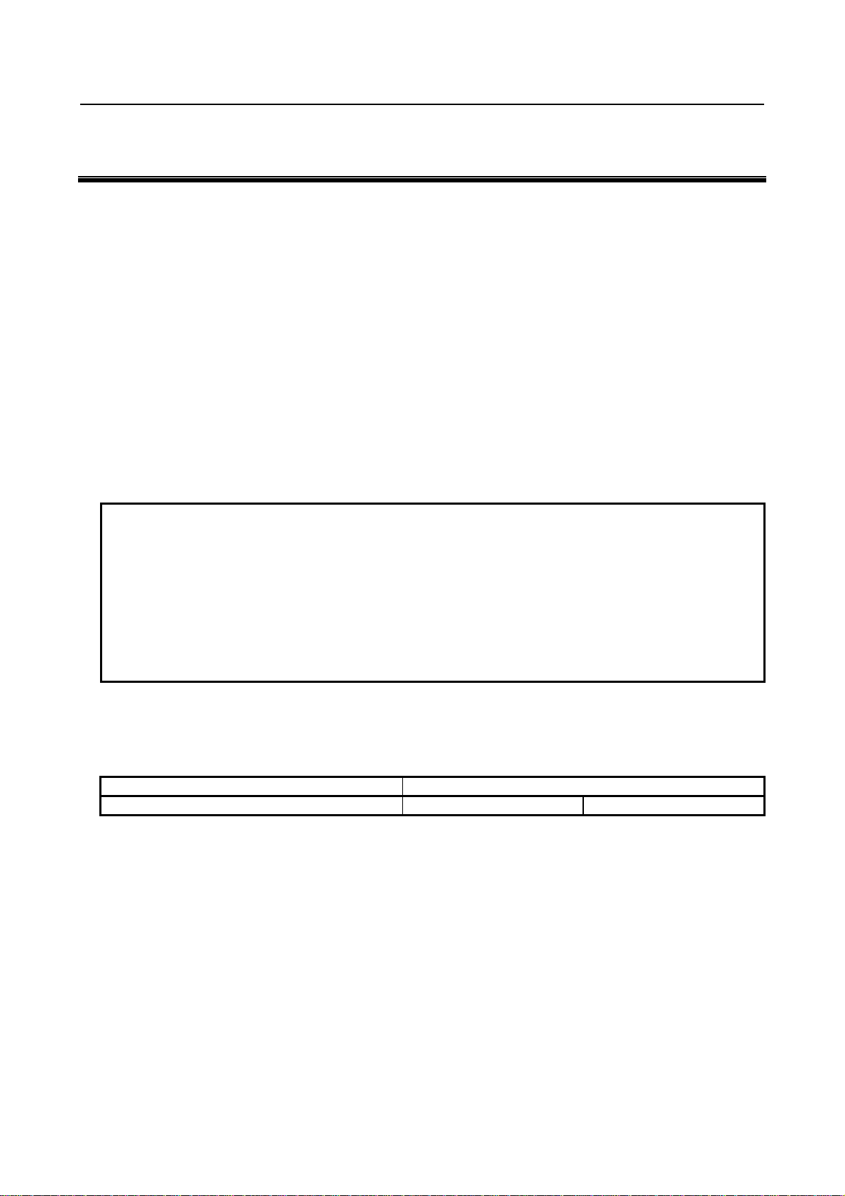
B-64554EN/01 GENERAL 1.GENERAL
1 GENERAL
This manual consists of the following parts:
About this manual
I. GENERAL
Describes chapter organization, applicable models, related manuals, and notes for reading this
manual.
II. PROGRAMMING
Describes each function: Format used to program functions in the NC language, explanations, and
limitations.
III. OPERATION
Describes the manual operation and automatic operation of a machine, procedures for inputting and
outputting data, and procedures for editing a program.
IV. MAINTENANCE
Describes procedures for daily maintenance and replacing batteries.
APPENDIX
Lists parameters, valid data ranges, and alarms.
NOTE
1 This manual does not detail the parameters not mentioned in the text. For details
of those parameters, refer to the Parameter Manual (B-64310EN, B-64560EN).
Parameters are used to set functions and operating conditions of a CNC
machine tool, and frequently-used values in advance. Usually, the machine tool
builder factory-sets parameters so that the user can use the machine tool easily.
2 This manual describes not only basic functions but also optional functions. Look
up the options incorporated into your system in the manual written by the
machine tool builder.
Applicable models
This manual describes the model indicated in the table below.
In the text, the abbreviations indicated below may be used.
Model name Abbreviation
FANUC Series 0i -PD 0i -PD Series 0i -PD
Special symbols
This manual uses the following symbols:
- IP
Indicates a combination of axes such as X_ Y_ Z_
In the underlined position following each address, a numeric value such as a coordinate value is placed
(used in PROGRAMMING.).
- ;
Indicates the end of a block. It actually corresponds to the ISO code LF or EIA code CR.
- 3 -
Page 28
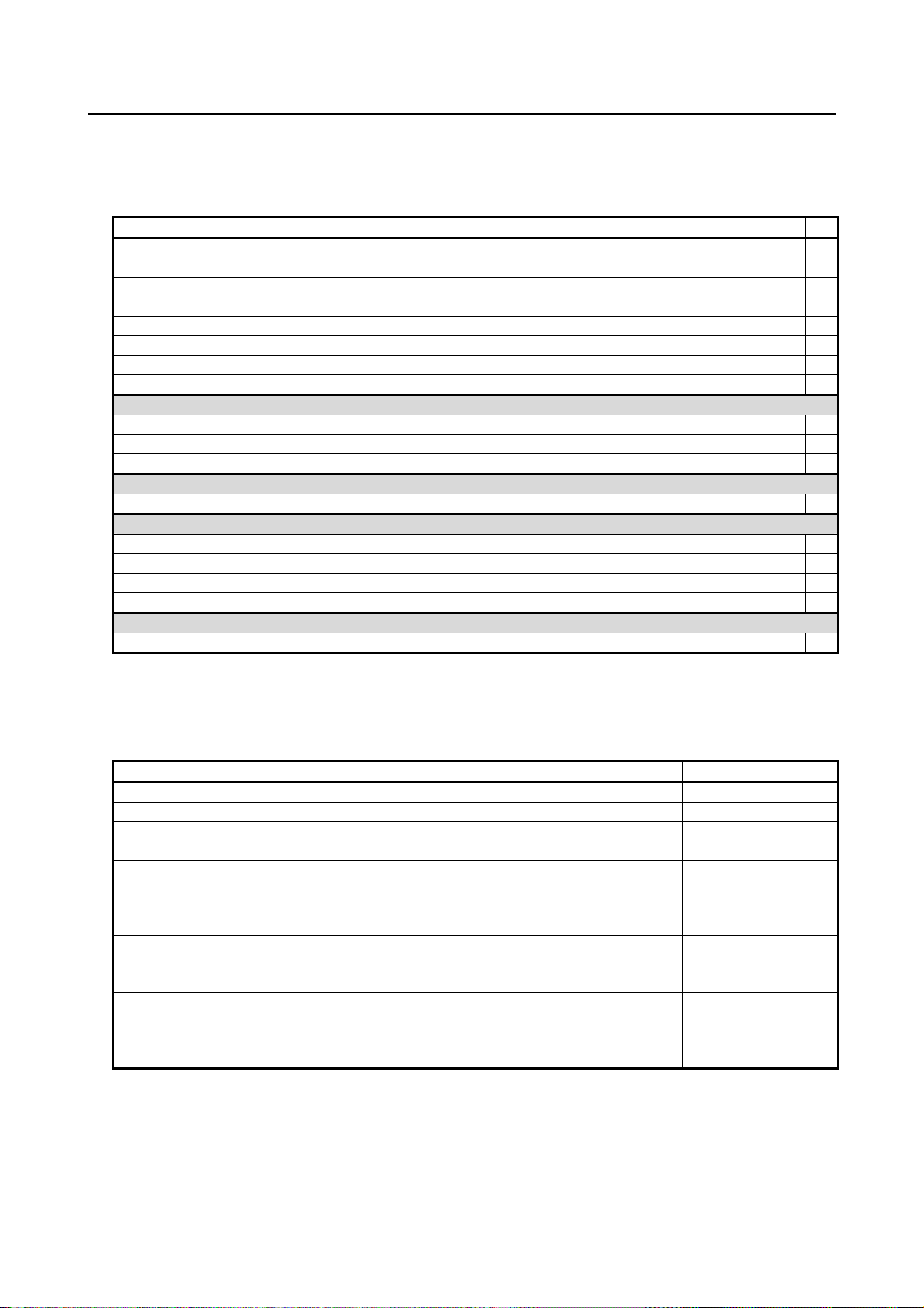
1.GENERAL GENERAL B-64554EN/01
Related manuals of Series 0i-PD
The following table lists the manuals related to Series 0i-PD. This manual is indicated by an asterisk(*).
Table 1 Related manuals
Manual name Specification number
FANUC Series 0i-D / 0i Mate-D DESCRIPTIONS
FANUC Series 0i-D / 0i Mate-D CONNECTION MANUAL (HARDWARE)
FANUC Series 0i-D / 0i Mate-D CONNECTION MANUAL (FUNCTION)
FANUC Series 0i-PD CONNECTION MANUAL (FUNCTION)
FANUC Series 0i-PD OPERATOR’S MANUAL
FANUC Series 0i-D / 0i Mate-D MAINTENANCE MANUAL
FANUC Series 0i-D / 0i Mate-D PARAMETER MANUAL
FANUC Series 0i-PD PARAMETER MANUAL
Programming
Macro Executor PROGRAMMING MANUAL B-64303EN-2
Macro Compiler PROGRAMMING MANUAL B-64303EN-5
C Language Executor PROGRAMMING MANUAL B-64303EN-3
PMC
PMC PROGRAMMING MANUAL B-64393EN
Network
PROFIBUS-DP Board CONNECTION MANUAL B-64403EN
Fast Ethernet / Fast Data Server OPERATOR’S MANUAL B-64414EN
DeviceNet Board CONNECTION MANUAL B-64443EN
FL-net Board CONNECTION MANUAL B-64453EN
Dual Check Safety
Dual Check Safety CONNECTION MANUAL B-64303EN-4
B-64302EN
B-64303EN
B-64303EN-1
B-64553EN
B-64554EN *
B-64305EN
B-64310EN
B-64560EN
Related manuals of SERVO MOTOR αi/βi series
The following table lists the manuals related to SERVO MOTOR αi/βi series
Table 2 Related manuals
Manual name Specification number
FANUC AC SERVO MOTOR αi series DESCRIPTIONS
FANUC AC SERVO MOTOR βi series DESCRIPTIONS
FANUC SERVO AMPLIFIER αi series DESCRIPTIONS
FANUC SERVO AMPLIFIER βi series DESCRIPTIONS
FANUC AC SERVO MOTOR αis series
FANUC AC SERVO MOTOR αi series
FANUC AC SPINDLE MOTOR αi series
FANUC SERVO AMPLIFIER αi series MAINTENANCE MANUAL
FANUC AC SERVO MOTOR βis series
FANUC AC SPINDLE MOTOR βi series
FANUC SERVO AMPLIFIER βi series MAINTENANCE MANUAL
FANUC AC SERVO MOTOR αi series
FANUC AC SERVO MOTOR βi series
FANUC LINEAR MOTOR LiS series
FANUC SYNCHRONOUS BUILT-IN SERVO MOTOR DiS series PARAMETER MANUAL
CNCs that are described in this manual can be connected to above servo motors.
This manual mainly assumes that the FANUC SERVO MOTOR αi series of servo motor is used. For
servo motor information, refer to the manuals for the servo motor that are actually connected.
B-65262EN
B-65302EN
B-65282EN
B-65322EN
B-65285EN
B-65325EN
B-65270EN
- 4 -
Page 29

B-64554EN/01 GENERAL 1.GENERAL
1.1 NOTES ON READING THIS MANUAL
CAUTION
1 The function of an CNC machine tool system depends not only on the CNC, but
on the combination of the machine tool, its magnetic cabinet, the servo system,
the CNC, the operator's panels, etc. It is too difficult to describe the function,
programming, and operation relating to all combinations. This manual generally
describes these from the stand-point of the CNC. So, for details on a particular
CNC machine tool, refer to the manual issued by the machine tool builder, which
should take precedence over this manual.
2 In the header field of each page of this manual, a chapter title is indicated so that
the reader can reference necessary information easily.
By finding a desired title first, the reader can reference necessary parts only.
3 This manual describes as many reasonable variations in equipment usage as
possible. It cannot address every combination of features, options and commands
that should not be attempted.
If a particular combination of operations is not described, it should not be attempted.
1.2 NOTES ON VARIOUS KINDS OF DATA
CAUTION
Machining programs, parameters, offset data, etc. are stored in the CNC unit
internal non-volatile memory. In general, these contents are not lost by the
switching ON/OFF of the power. However, it is possible that a state can occur
where precious data stored in the non-volatile memory has to be deleted,
because of deletions from a maloperation, or by a failure restoration. In order to
restore rapidly when this kind of mishap occurs, it is recommended that you
create a copy of the various kinds of data beforehand.
- 5 -
Page 30

Page 31

II. PROGRAMMING
Page 32

Page 33

B-64554EN/01 PROGRAMMING 1.GENERAL
1 GENERAL
Chapter 1, "GENERAL", consists of the following sections:
1.1 TOOL MOVEMENT ALONG WORKPIECE PARTS FIGURE-INTERPOLATION.....................10
1.2 FEED-FEED FUNCTION ..................................................................................................................12
1.3 PART DRAWING AND TOOL MOVEMENT.................................................................................12
1.4 SELECTION OF TOOL USED FOR VARIOUS MACHINING - TOOL FUNCTION...................16
1.5 COMMAND FOR MACHINE OPERATIONS - AUXILIARY FUNCTION...................................16
1.6 PROGRAM CONFIGURATION.......................................................................................................17
1.7 TOOL MOVEMENT RANGE - STROKE ........................................................................................19
(1) Punching is performed after positioning
..............Punching function
Punching
Tool T01
(2) Continuous, repetitive punching can be performed without halting the pressing process after
positioning
.............Nibbling function
Punching
Tool T02
Program command
G00 X_ Y_ T01 ;
X_ T02 ;
Program command
M12 ;
G00 X_ Q_ ;
X_ Y_ ;
:
:
M13 ;
- 9 -
Page 34

1.GENERAL PROGRAMMING B-64554EN/01
Y
(3) By giving commands for block, it is possible to perform at multiple positions in a given profile.
.............Pattern function
#1 to #n:The order of punching operation
#(n−1)
#n
d
#2
#1
θ
In case of line at angle (G76)
#3
Program command
G76 I_ J_ K_ ;
+X
This CNC supports the eight different patterns that will be used most frequently.
1.1 TOOL MOVEMENT ALONG WORKPIECE PARTS FIGURE-
INTERPOLATION
The tool moves along straight lines and arcs constituting the workpiece parts figure (See Chapter,
“INTERPOLATION FUNCTIONS”).
Explanation
The function of moving the tool along straight lines and arcs is called the interpolation.
- Tool movement along a straight line
Program
G01X_Y_T_;
X_;
Tool
Workpiece
X
Fig. 1.1 (a) Tool movement along a straight line
- 10 -
Page 35

B-64554EN/01 PROGRAMMING 1.GENERAL
Y
- Tool movement along an arc
Program
G03X_Y_R_;
Tool
Workpiece
X
Fig. 1.1 (b) Tool movement along an arc
The term interpolation refers to an operation in which the tool moves along a straight line or arc in the
way described above.
Symbols of the programmed commands G01, G02, ... are called the preparatory function and specify the
type of interpolation conducted in the control unit.
(a) Movement along straight line
G01 Y_ ;
X_ Y_ ;
CNC
(b) Movement along arc
G03X_ Y_ R_ ;
X axis
Interpolation
Y axis
a)Movement
along straight
line
b)Movement
along arc
Fig. 1.1 (c) Interpolation function
Tool
movement
NOTE
Some machines move tables instead of tools but this manual assumes that tools
are moved against workpieces.
- 11 -
Page 36

1.GENERAL PROGRAMMING B-64554EN/01
y
1.2 FEED-FEED FUNCTION
Movement of the tool at a specified speed for punching a workpiece is called the feed.
mm/min
F
Workpiece
Tool
Fig. 1.2 (a) Feed function
For example, to feed the tool at a rate of 150 mm/min (feed per minute), specify the following in the
program:
F150.0
The function of deciding the feed rate is called the feed function (See Chapter, “FEED FUNCTIONS”).
1.3 PART DRAWING AND TOOL MOVEMENT
1.3.1 Reference Position (Machine-specific Position)
A CNC machine tool is provided with a fixed position. Normally, tool change and programming of
absolute zero point as described later are performed at this position. This position is called the reference
position.
End lo cator
Distance between reference point
and workpiece holder is intrinsicall
determined according to machines.
Workpiece holder
The distance between the
reference point and the end
locator is intrinsically
determined according to
machines.
Fig. 1.3.1 (a) Reference position
Reference point
- 12 -
Page 37

B-64554EN/01 PROGRAMMING 1.GENERAL
Explanation
The tool can be moved to the reference position in two ways:
1. Manual reference position return (See Section, “MANUAL REFERENCE POSITION RETURN”)
Reference position return is performed by manual button operation.
2. Automatic reference position return (See Section, “REFERENCE POSITION RETURN”)
In general, manual reference position return is performed first after the power is turned on. In order
to move the tool to the reference position for tool change thereafter, the function of automatic
reference position return is used.
1.3.2 Coordinate System on Part Drawing and Coordinate System
Specified by CNC - Coordinate System
Z
Y
Program
Z
Y
X
Part drawing
Fig. 1.3.2 (a) Coordinate system
X
Tool
Z
Workpiece
Machine tool
Coordinate system
CNC
Command
Tool
Y
X
Explanation
- Coordinate system
The following two coordinate systems are specified at different locations:
(See Chapter, “ COORDINATE SYSTEM”)
1 Coordinate system on part drawing
The coordinate system is written on the part drawing. As the program data, the coordinate values on
this coordinate system are used.
2. Coordinate system specified by the CNC
The coordinate system is prepared on the actual machine tool table. This can be achieved by
programming the distance from the current position of the tool to the zero point of the coordinate
system to be set.
- 13 -
Page 38

1.GENERAL PROGRAMMING B-64554EN/01
X
r
A
Program
origin
Fig. 1.3.2 (b) Coordinate system specified by the CNC
Y
230
300
Present tool position
Distance to the zero point of a coordinate system to be set
Concrete programming methods for setting coordinate systems specified by the CNC are explained in
Chapter, “ COORDINATE SYSTEM”
The positional relation between these two coordinate systems is determined when a workpiece is set on
the table.
The tool moves on the coordinate system specified by the CNC in accordance with the command program
generated with respect to the coordinate system on the part drawing, and cuts a workpiece into a shape on
the drawing.
Therefore, in order to correctly cut the workpiece as specified on the drawing, the two coordinate systems
must be set at the same position.
Methods of setting the two coordinate systems in the same position
When a workpiece is set on the table, these two coordinate systems lay as follows:
The tool moves on the coordinate system specified by the CNC in accordance with the command program
generated with respect to the coordinate system on the part drawing, and cut a workpiece into a shape on
the drawing.
Therefore, in order to correctly cut the workpiece as specified on the drawing, the two coordinate systems
must be set at the same position.
To set the two coordinate systems at the same position, when setting a workpiece to be machined to
general turret punch press, the workpiece is held by the workpiece holders after positioning it by applying
the end face of the workpiece to the end locator and workpiece holders mounted on the machine as
illustrated below.
Y
Face B
End locator
Workpiece holde
図1.3.2 (c)
Face
Workpiece
- 14 -
X
Page 39

B-64554EN/01 PROGRAMMING 1.GENERAL
A
A
Generally, the distance between the reference point and the and locator as well as the distance between
the reference point and the workpiece holders are intrinsically determined according to machines, and
they are separated from each other by a fixed distance.
1.3.3 How to Indicate Command Dimensions for Moving the Tool
(Absolute and Incremental Programming)
Explanation
Command for moving the tool can be indicated by absolute command or incremental command (See
Section, “ABSOLUTE AND INCREMENTAL PROGRAMMING”).
- Absolute command
The tool moves to a point at "the distance from zero point of the coordinate system" that is to the position
of the coordinate values.
Y
Tool
B(10,30)
Command specifying movement
from point A to point B
G90 X10.0 Y30.0 ;
Coordinates of point B
- Incremental command
Specify the distance from the previous tool position to the next tool position.
Tool
Y
Y=-30
X=40
B
X
X
Command specifying movement
from point A to point B
G91 X40.0 Y-30.0 ;
Distance and direction for movement
along each axis
- 15 -
Page 40

1.GENERAL PROGRAMMING B-64554EN/01
r
1.4 SELECTION OF TOOL USED FOR VARIOUS MACHINING -
TOOL FUNCTION
When drilling, tapping, or the like, is performed, it is necessary to select a suitable tool. When a number
is assigned to each tool and the number is specified in the program, the corresponding tool is selected.
03
04
05
06
07
<When No.01 is assigned to a punching tool>
When the tool is stored at location 01 in the turret, the tool can be selected by specifying T01. This is
called the tool function (See Chapter, “TOOL FUNCTION (T FUNCTION)”).
08
02
01
Turret
Tool number
1.5 COMMAND FOR MACHINE OPERATIONS - AUXILIARY
FUNCTION
During machining, on–off operation of workpiece holder and clamper is performed.
For this purpose, on–off operations of workpiece holder and clamper should be controlled.
Workpiece
Clampe
The function of specifying the on–off operations of the components of the machine is called the
miscellaneous function. In general, the function is specified by and M code.
Workpiece holder
- 16 -
Page 41

B-64554EN/01 PROGRAMMING 1.GENERAL
A
1.6 PROGRAM CONFIGURATION
A group of commands given to the CNC for operating the machine is called the program. By specifying
the commands, the tool is moved along a straight line or an arc.
In the program, specify the commands in the sequence of actual tool movements.
Block
Block
Tool movement
Block
sequence
Program
Fig. 1.6 (a) Program configuration
Block
:
:
:
:
Block
A group of commands at each step of the sequence is called the block. The program consists of a group of
blocks for a series of machining. The number for discriminating each block is called the sequence number,
and the number for discriminating each program is called the program number (See Chapter,
“PROGRAM CONFIGURATION”).
Explanation
The block and the program have the following configurations.
- Block
1 block
Nxxxxx Gxx Xxxx.x Yxxx.x Mxx Sxx Txx ;
Sequence
number
Preparatory
function
Dimension word
Fig. 1.6 (b) Block configuration
uxiliary
function
S
function
Tool
function
End of block
A block starts with a sequence number to identify the block and ends with an end-of-block code.
This manual indicates the end-of-block code by; (LF in the ISO code and CR in the EIA code).
The contents of the dimension word depend on the preparatory function. In this manual, the portion of the
dimension word may be represent as IP_.
- 17 -
Page 42

1.GENERAL PROGRAMMING B-64554EN/01
- Program
;
Oxxxxx ;
Program number
Block
Block
Block
:
:
:
M30 ;
:
:
:
End of program
Fig. 1.6 (c) Program configuration
Normally, a program number is specified after the end-of-block (;) code at the beginning of the program,
and a program end code (M02 or M30) is specified at the end of the program.
- Main program and subprogram
When machining of the same pattern appears at many portions of a program, a program for the pattern is
created. This is called the subprogram. On the other hand, the original program is called the main
program. When a subprogram execution command appears during execution of the main program,
commands of the subprogram are executed. When execution of the subprogram is finished, the sequence
returns to the main program.
Main program
:
:
M98P1001
:
:
:
Subprogram #1
O1001
M98P1002
:
:
M98P1001
:
:
:
M99
Subprogram #2
O1002
M99
Fig. 1.6 (d) Subprogram execution
- 18 -
Page 43
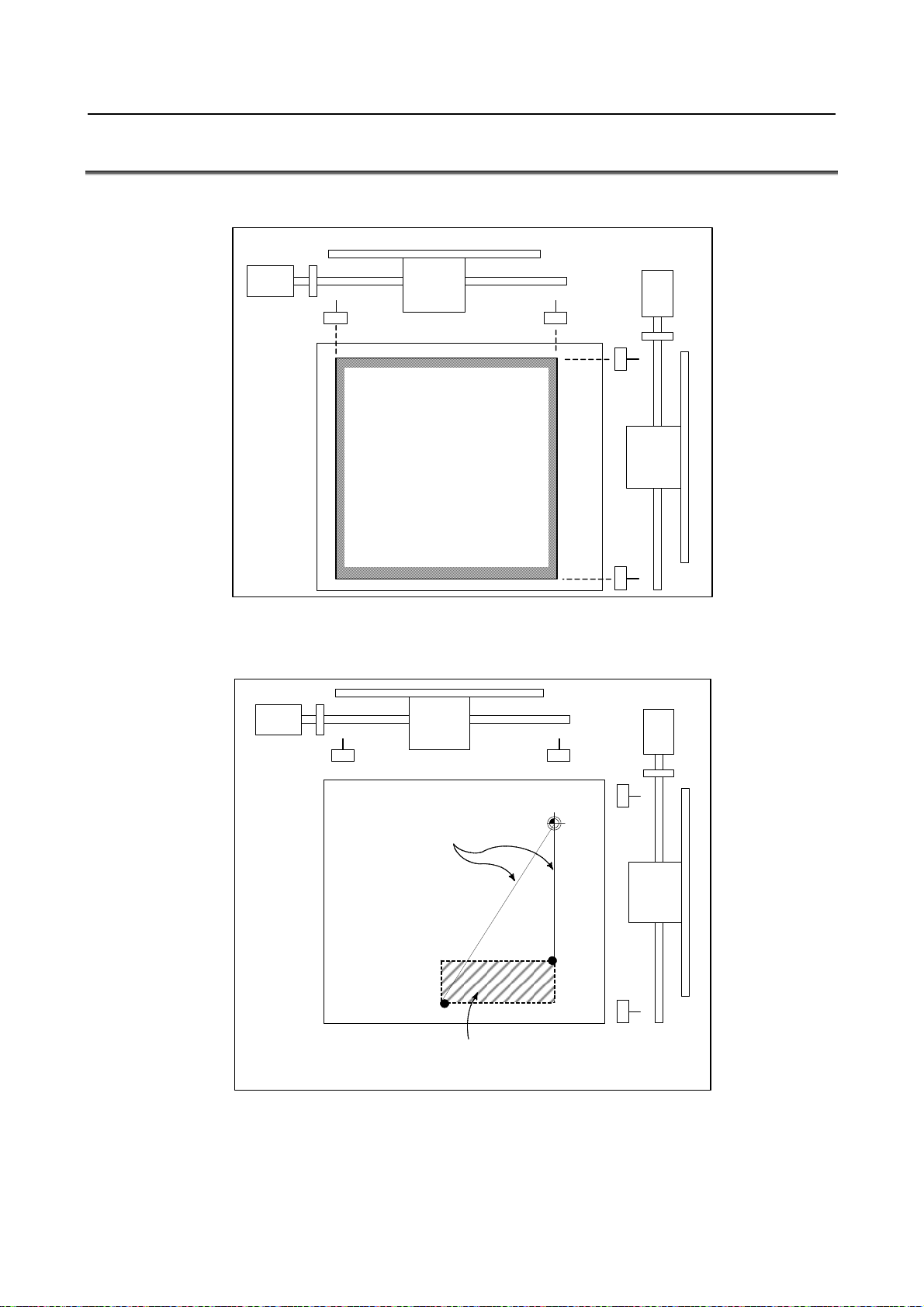
B-64554EN/01 PROGRAMMING 1.GENERAL
y
1.7 TOOL MOVEMENT RANGE - STROKE
Limit switches are installed at the ends of each axis on the machine to prevent tools from moving beyond
the ends. The range in which tools can move is called the stroke.
Machine zero point
Motor
Limit
switch
Stroke area
Besides strokes defined with limit switches, the operator can define an area which the tool cannot enter
using a program or data in memory. This function is called stroke check (See Section, “STORED
STROKE CHECK”).
Motor
Limit
switch
Machine zero point
these distances.
Specif
Tools cannot enter this area. The area is
specified by data in memory or a program.
- 19 -
Page 44

2.CONTROLLED AXES PROGRAMMING B-64554EN/01
2 CONTROLLED AXES
Chapter 2, "CONTROLLED AXES", consists of the following sections:
2.1 NUMBER OF CONTROLLED AXES...............................................................................................20
2.2 NAMES OF AXES.............................................................................................................................20
2.3 INCREMENT SYSTEM.....................................................................................................................20
2.4 MAXIMUM STROKE........................................................................................................................21
2.1 NUMBER OF CONTROLLED AXES
Explanation
The number of controlled axes used with this NC system is as indicated below.
Controlled paths 1 path
Total number of controlled axes Max. 7 axes
Feed axes Max. 7 axes
Simultaneously controlled axes Max. 4 axes
Axis control by PMC Max. 4 axes at a time
NOTE
1 The maximum number of controlled axes that can be used is limited depending
on the option configuration. Refer to the manual provided by the machine tool
builder for details.
2 The number of simultaneously controllable axes for manual operation (jog feed,
manual reference position return, or manual rapid traverse) is 1 or 3 (1 when bit
0 (JAX) of parameter No. 1002 is set to 0 and 3 when it is set to 1).
Series 0i-PD
2.2 NAMES OF AXES
Explanation
The move axes of machine tools are assigned names. These names are referred to as addresses or axis
names. Axis names are determined according to the machine tool. The naming rules comply with
standards such as the ISO standards.
NOTE
Axis names are predetermined according to the machine used. Refer to the
manual supplied by the machine tool builder.
2.3 INCREMENT SYSTEM
Explanation
The increment system consists of the least input increment (for input) and least command increment (for
output). The least input increment is the least increment for programming the travel distance. The least
command increment is the least increment for moving the tool on the machine. Both increments are
represented in mm, inches, or deg.
- 20 -
Page 45

B-64554EN/01 PROGRAMMING 2.CONTROLLED AXES
Two types of increment systems are available as indicated in Table 2.3 (a). For each axis, an increment
system can be set using a bit from bit 0 (ISA) of parameter No. 1013.
Table 2.3 (a) Increment system
Name of increment system Least input increment Least command increment
0.01 mm 0.01 mm
IS-A
IS-B
0.001 inch 0.001 inch
0.01 deg 0.01 deg
0.001 mm 0.001 mm
0.0001 inch 0.0001 inch
0.001 deg 0.001 deg
The least command increment is either metric or inch depending on the machine tool. Set metric or inch
to the bit 0 (INM) of parameter No. 0100.
For selection between metric and inch for the least input increment, G code (G20 or G21) or a setting
parameter selects it.
Combined use of the inch system and the metric system is not allowed. There are functions that cannot be
used between axes with different unit systems (circular interpolation, cutter compensation, etc.). For the
increment system, see the machine tool builder's manual.
2.4 MAXIMUM STROKE
Explanation
The maximum stroke controlled by this CNC is shown in the table below:
Maximum stroke = Least command increment × 999999999 (99999999 for IS-A)
Commands that exceed the maximum stroke are not permitted.
Table 2.4 (a) Maximum strokes
Name of increment system Least input increment Maximum stroke
0.01 mm ±999999.99 mm
IS-A
IS-B
NOTE
The actual stroke depends on the machine tool.
0.001 inch ±99999.999 inch
0.01 deg ±999999.99 deg
0.001 mm ±999999.999 mm
0.0001 inch ±99999.9999 inch
0.001 deg ±999999.999 deg
- 21 -
Page 46

3. PREPARATORY FUNCTION
(G FUNCTION)
PROGRAMMING B-64554EN/01
3 PREPARATORY FUNCTION (G FUNCTION)
A number following address G determines the meaning of the command for the concerned block.
G codes are divided into the following two types.
Type Meaning
One-shot G code The G code is effective only in the block in which it is specified.
Modal G code The G code is effective until another G code of the same group is specified.
(Example)
G01 and G00 are modal G codes in group 01.
G01 X_ ;
Y_ ; G01 is effective in this range.
X_ ;
G00 Y_ ;
:
Explanation
1. When the clear state (bit 6 (CLR) of parameter No. 3402) is set at power-up or reset, the modal G
codes are placed in the states described below.
(1) The modal G codes are placed in the states marked with
(2) G20 and G21 remain unchanged when the clear state is set at power-up or reset.
(3) Which status G22 or G23 at power on is set by bit 7 (G23) of parameter No. 3402. However,
G22 and G23 remain unchanged when the clear state is set at reset.
(4) The user can select G00 or G01 by setting bit 0 (G01) of parameter No. 3402.
(5) The user can select G90 or G91 by setting bit 3 (G91) of parameter No. 3402.
(6) In the machining center system, the user can select G17, G18, or G19 by setting bits 1 (G18)
and 2 (G19) of parameter No. 3401.
2. G codes other than G10 and G11 are one-shot G codes.
3. When a G code not listed in the G code list is specified, or a G code that has no corresponding
option is specified, alarm PS0010 occurs.
4. Multiple G codes can be specified in the same block if each G code belongs to a different g roup. If
multiple G codes that belong to the same group are specified in the same block, only the last G code
specified is valid.
5. G codes are indicated by group.
6. There are two G code systems in the FANUC Series 0i-PD (Table3.1 (a)). Select a G code system
using bit 6 (GSB) of parameter No. 3401.
as indicated in Table3.1 (a).
- 22 -
Page 47

3.PREPARATORY FUNCTION
B-64554EN/01 PROGRAMMING
(G FUNCTION)
3.1 G CODE LIST
Table3.1 (a) G code list
G code system
A B
G00 G00 Positioning (rapid traverse)
G01 G01 Linear interpolation (cutting feed)
G02 G02 Circular interpolation CW or helical interpolation CW
G03 G03
G04 G04 Dwell
G05.1 G05.1 AI advanced preview control (*1)
G05.4 G05.4 High-speed HRV current control on/off
G09 G09 Exact stop
G10 G10 Programmable data input
G11 G11
G17 G17 XpYp plane selection
G18 G18 ZpXp plane selection
G19 G19
G20 G20 Input in inch
G21 G21
G22 G22 Stored stroke check function on
G23 G23
G26 G26 Bolt hole circle
G28 G50 Automatic reference point return
G32 G32 Automatic safety zone setting
G33 G33 Skip function
G38 G38 Bending compensation X
G39 G39
G40 G40 Tool radius compensation : cancel
G41 G41 Tool radius compensation : left
G42 G42
G40.1(G150) G40.1(G150) Normal direction control cancel mode
G41.1(G151) G41.1(G151) Normal direction control on : left
G42.1(G152) G42.1(G152)
G45 G45 Linear punching
G46 G46 Circular punching (CW)
G47 G47
G50 G34 Scaling cancel
G51 G35
G52 G93 Local coordinate system setting
G53 G53
G54 G54 Workpiece coordinate system 1 selection
G55 G55 Workpiece coordinate system 2 selection
G56 G56 Workpiece coordinate system 3 selection
G57 G57 Workpiece coordinate system 4 selection
G58 G58 Workpiece coordinate system 5 selection
G59 G59
G61 G61 Exact stop mode
G62 G62 Automatic corner override
G64 G64
G65 G95 00 Macro call
G66 G96 Macro modal call
G67 G97
Group Function
01
Circular interpolation CCW or helical interpolation CCW
00
Programmable data input mode cancel
Xp: X axis or its parallel axis
02
YpZp plane selection
06
Input in mm
04
Stored stroke check function off
00
Bending compensation X
07
Tool radius compensation : right
18
Normal direction control on : right
00
Circular punching (CCW)
11
Scaling
00
Machine coordinate system setting
14
Workpiece coordinate system 6 selection
15
Cutting mode
12
Macro modal call cancel
Yp: Y axis or its parallel axis
Zp: Z axis or its parallel axis
- 23 -
Page 48

3. PREPARATORY FUNCTION
(G FUNCTION)
PROGRAMMING B-64554EN/01
G code system
A B
G68 G68 Circular nibbling
G69 G69 Linear nibbling
G70 G70 Positioning & press off
G72 G72 Standard point command
G73 G75 Multi–piece machining command X
G74 G76 Multi–piece machining command Y
G75 G27 Automatic repositioning
G76 G28 Line at angle
G77 G29 Arc
G78 G36
G79 G37
G84 G84 Coordinate system rotation start
G85 G85
G86 G66 Share proof
G87 G67 Square
G88 G78 Radius
G89 G79
G90 G90 Absolute programming
G91 G91
G91.1 G91.1 Checking the maximum incremental amount specified
G92 G92 Setting for workpiece coordinate system
G92.1 G92.1 Workpiece coordinate system preset
G98 G98
*1: In punching mode, AI Advanced Preview Control I function cannot be used.
Group Function
00
GridⅠ
GridⅡ
16
Coordinate system rotation cancel
00
Cut at angle
03
Incremental programming
00
Coordinate system setting (Multi–piece machining)
- 24 -
Page 49

B-64554EN/01 PROGRAMMING 4.INTERPOLATION FUNCTIONS
4 INTERPOLATION FUNCTIONS
Interpolation functions specify the way to make an axis movement (in other words, a movement of the
tool with respect to the workpiece or table).
Chapter 4, "INTERPOLATION FUNCTIONS", consists of the following sections:
4.1 POSITIONING (G00).........................................................................................................................25
4.2 LINEAR INTERPOLATION (G01)...................................................................................................26
4.3 CIRCULAR INTERPOLATION (G02, G03).....................................................................................28
4.4 HELICAL INTERPOLATION (G02, G03)........................................................................................32
4.5 SKIP FUNCTION (G33) ....................................................................................................................33
4.6 MULTI-STEP SKIP (G33).................................................................................................................35
4.7 HIGH-SPEED SKIP SIGNAL (G33) .................................................................................................36
4.8 SKIP POSITION MACRO VARIABLE IMPROVEMENT..............................................................36
4.9 TORQUE LIMIT SKIP.......................................................................................................................36
4.1 POSITIONING (G00)
The G00 command moves a tool to the position in the workpiece system specified with an absolute or an
incremental programming at a rapid traverse rate.
In the absolute programming, coordinate value of the end point is programmed.
In the incremental programming the distance the tool moves is programmed.
Format
G00 IP_ ;
IP_ : For an absolute programming, the coordinates of an end point, and for an
incremental programming, the distance the tool moves.
Explanation
Either of the following tool paths can be selected according to bit 1 (LRP) of parameter No. 1401.
• Nonlinear interpolation type positioning
The tool is positioned with the rapid traverse rate for each axis separately. The tool path is normally
straight.
• Linear interpolation type positioning
The tool is positioned within the shortest possible time at a speed that is not more than the rapid
traverse rate for each axis.
Linear interpolation type positioning
Start position
End position
The rapid traverse rate in G00 command is set to the parameter No. 1420 for each axis independently by
the machine tool builder. In the positioning mode actuated by G00, the tool is accelerated to a
predetermined speed at the start of a block and is decelerated at the end of a block. Execution proceeds to
the next block after confirming the in-position.
Non linear interpolation type positioning
- 25 -
Page 50

4.INTERPOLATION FUNCTIONS PROGRAMMING B-64554EN/01
"In-position " means that the feed motor is within the specified range.
This range is determined by the machine tool builder by setting to parameter No. 1826.
When G00X_Y_T ; is specified in a machine having a turret axis (T–axis), the X and Y axes move to the
specified positions at rapid traverse rate and also the T–axis moves at the predetermined rapid traverse
rate in such a way as to select a specified tool number.
In a machine provided with a die angle index (C–axis), if “G00X_Y_ ; ” is specified, the X, Y, and C axes
move simultaneously at the predetermined rapid traverse rate.
Refer to “C axis control” for the details.
Since this control system treats the turret punch press as a controlled system, the tool moves to the
commanded position as fast as possible for punching as the basic principle.
Accordingly, the tool is positioned at rapid traverse, punching is done after axis movement in the G00
mode, in principle.
Refer to “Punch function” for details.
CAUTION
For T– or C–axis command blocks, nonlinear interpolation positioning is
performed, even if linear interpolation positioning is specified.
And, for block including G28 or G53 command, nonlinear interpolation
positioning is performed.
Please pay attention for the interference between tool and workpiece.
4.2 LINEAR INTERPOLATION (G01)
Tools can move along a line.
Format
G01 IP_ F_ ;
IP_ : For an absolute programming, the coordinates of an end point, and for an incremental
programming, the distance the tool moves.
F_ : Speed of tool feed (Feedrate)
Explanation
A tools move along a line to the specified position at the feedrate specified in F.
The feedrate specified in F is effective until a new value is specified. It need not be specified for each
block.
The feedrate commanded by the F code is measured along the tool path. If the F code is not commanded,
the feedrate is regarded as zero.
The feedrate of each axis direction is as follows.
- 26 -
Page 51

B-64554EN/01 PROGRAMMING 4.INTERPOLATION FUNCTIONS
α
β
γ
G01
α
β
Feed rate of α axis direction : f
Feed rate of β axis direction :
Feed rate of γ axis direction :
Feed rate of ζ axis direction :
ζ
Ff ;
γ
ζ
α
α
2222
ζγβα
+++=L
F ×=
β
F ×=
γ
γ
f
F ×=
ζ
f
F ×=
L
β
f
L
L
ζ
L
The feedrate of the rotary axis is commanded in the unit of deg/min (the unit is decimal point position).
When the straight line axis α (such as X, Y, or Z) and the rotating axis β (such as A, B, or C) are linearly
interpolated, the feedrate is that in which the tangential feedrate in the α and β Cartesian coordinate
system is commanded by F (mm/min).
β-axis feedrate is obtained ; at first, the time required for distribution is calculated by using the above
formula, then the β-axis feedrate unit is changed to deg/min.
A calculation example is as follows.
G91 G01 X20.0B40.0 F300.0 ;
This changes the unit of the C axis from 40.0 deg to 40mm with metric input.
The time required for distribution is calculated as follows:
22
+
300
4020
)(14907.0 mm
The feedrate for the C axis is
40
14907.0
mindeg/3.268
In simultaneous 3 axes control, the feedrate is calculated the same way as in 2 axes control.
Limitations
• Punching (1–cycle pressing) is not performed in G01 mode. However, when bit 7 (CPF) of
parameter No.16001 is set to 1, punching can be performed on the end point in G01 mode.
• T code can’t be specified in G01 mode. If specified, an alarm (PS 4600) occurs.
However, when T code is specified independently and bit 0 (NMG) of parameter No.16181 is set, an
alarm does not occur.
Example
- Linear interpolation
(G91) G01X200.0Y100.0F200.0;
Y axis
100.0
0 (Start point)
(End point)
200.0
X axis
- 27 -
Page 52

4.INTERPOLATION FUNCTIONS PROGRAMMING B-64554EN/01
- Feedrate for the rotary axis
G91G01C-90.0 F300.0 ;Feed rate of 300deg/min
(Start point)
90
°
(End point)
Feedrate is 300 deg/min
4.3 CIRCULAR INTERPOLATION (G02, G03)
The command below will move a tool along a circular arc.
Format
Arc in the XpYp plane
G17
G03
Xp_ Yp_
R_
F_ ;
Arc in the ZpXp plane
G02 I_ K_
G02 I_ J_
G18
G03
Zp_ Xp_
R_
F_ ;
Arc in the YpZp plane
G02 J_ K_
G19
G03
Command Description
G17 Specification of arc on XpYp plane
G18 Specification of arc on ZpXp plane
G19 Specification of arc on YpZp plane
G02 Circular Interpolation : Clockwise direction (CW)
G03 Circular Interpolation : Counterclockwise direction (CCW)
Xp_ Command values of X axis or its parallel axis (set by parameter No. 1022)
Yp
_
Zp
_
I_ Xp axis distance from the start point to the center of an arc with sign
J_ Yp axis distance from the start point to the center of an arc with sign
K_ Zp axis distance from the start point to the center of an arc with sign
R_ Arc radius (with sign, radius value for lathe cutting)
F_ Feedrate along the arc
Yp_ Zp_
F_ ;
R_
Command values of Y axis or its parallel axis (set by parameter No. 1022)
Command values of Z axis or its parallel axis (set by parameter No. 1022)
Explanation
- Direction of the circular interpolation
"Clockwise"(G02) and "counterclockwise"(G03) on the XpYp plane (ZpXp plane or YpZp plane) are
defined when the XpYp plane is viewed in the positive-to-negative direction of the Zp axis (Yp axis or
Xp axis, respectively) in the Cartesian coordinate system. See the figure below (Fig. 4.3 (a)).
- 28 -
Page 53

B-64554EN/01 PROGRAMMING 4.INTERPOLATION FUNCTIONS
Y
j
j
G03
G02
G17
X
X
G03
G02
G18
Fig. 4.3 (a)
Z
G02
G19
G03
YZ
- Distance moved on an arc
The end point of an arc is specified by address Xp, Yp or Zp, and is expressed as an absolute or
incremental value according to G90 or G91. For the incremental value, the distance of the end point
which is viewed from the start point of the arc is specified with sign.
- Distance from the start point to the center of arc
The arc center is specified by addresses I, J, and K for the Xp, Yp, and Zp axes, respectively. The
numerical value following I, J, or K, however, is a vector component in which the arc center is seen from
the start point, and is always specified as an incremental value irrespective of G90 and G91, as shown
below (Fig. 4.3 (b)).
I, J, and K must be signed according to the direction.
End point (x,y)
y
x
End point (z,x)
x
Start
i
point
z
k
Start
point
End point (y,z)
z
y
Start
point
Center
Center
i
Center
Fig. 4.3 (b)
k
I0, J0, and K0 can be omitted.
When X
p, Yp , and Zp are omitted (the end point is the same as the start point) and the center is specified
with I, J, and K, a 360° arc (circle) is specified.
G02I; Command for a circle
If the difference between the radius at the start point and that at the end point exceeds the value in a
parameter (No.3410), an alarm (PS0020) occurs.
- Arc radius
The distance between an arc and the center of a circle that contains the arc can be specified using the
radius, R, of the circle instead of I, J, and K.
In this case, one arc is less than 180°, and the other is more than 180° are considered. When an arc
exceeding 180° is commanded, the radius must be specified with a negative value. If Xp, Yp, and Zp are
all omitted, if the end point is located at the same position as the start point and when R is used, an arc of
0° is programmed
G02R_ ; (The cutter does not move.)
- 29 -
Page 54

4.INTERPOLATION FUNCTIONS PROGRAMMING B-64554EN/01
For arc <1> (less than 180°)
G91 G02 XP60.0 YP55.0 R50.0
For arc <2> (greater than 180°)
G91 G02 XP60.0 YP55.0 R-50.0
F300.0 ;
F300.0 ;
<2>
r=50mm
End point
<1>
Start point
r=50mm
Y
X
- Feedrate
The feedrate in circular interpolation is equal to the feedrate specified by the F code, and the feedrate
along the arc (the tangential feedrate of the arc) is controlled to be the specified feedrate.
The error between the specified feedrate and the actual tool feedrate is ±2% or less. However, this
feedrate is measured along the arc after the tool radius compensation is applied
Limitation
- Simultaneously specifying R with I, J, and K
If I, J, K, and R addresses are specified simultaneously, the arc specified by address R takes precedence
and the other are ignored.
- Specifying an axis that is not contained in the specified plane
If an axis not comprising the specified plane is commanded, an alarm PS0021 occurs.
For example, if the X-axis and a U-axis parallel to the X-axis are specified when the XY plane is
specified
- Specifying a semicircle with R
When an arc having a center angle approaching 180° is specified, the calculated center coordinates may
contain an error. In such a case, specify the center of the arc with I, J, and K.
- Difference in the radius between the start and end points
If the difference in the radius between the start and end points of the arc exceeds the value specified in
parameter No. 3410, alarm PS0020 is generated.
When an end point does not lie on the arc, a spiral results, as shown below.
- 30 -
Page 55

B-64554EN/01 PROGRAMMING 4.INTERPOLATION FUNCTIONS
Start point
s
γ
e
γ
Radius
Start point
End point
e
γ
(t)
γ
θ
(t)
θ
s
γ
Center
End point
θ
Center
s(t)
+=
θ
ts)e(
)(θγγγγ−
θ
The arc radius changes linearly with the center angle θ(t). Spiral interpolation is performed using a
circular command that specifies one arc radius for the start point and another arc radius for the end point.
To use spiral interpolation, set a large value in parameter No. 3410, used to specify the limit on the arc
radius error.
- Punching operation
Punching (1–cycle pressing) is not performed in G02 and G03 mode. However, when bit 7 (CPF) of
parameter No.16001 is set to 1, punching can be performed on the end point in G02 or G03 mode.
- T code
If T command is specified in G02 and G03 mode, however, when T code is specified independently and
bit 0 (NMG) of parameter No. 16181 is set, an alarm (PS 4600) doesn’t occur.
Example
Y axis
100
60
40
0
The above tool path can be programmed as follows;
(1) In absolute programming
G92X200.0 Y40.0 Z0 ;
G90 G03 X140.0 Y100.0 R60.0 F300. ;
G02 X120.0 Y60.0 R50.0 ;
or
G92X200.0 Y40.0Z0 ;
G90 G03 X140.0 Y100.0I-60.0 F300. ;
G02 X120.0 Y60.0I-50.0 ;
- 31 -
50
90 120 140
60
200
X axis
Page 56

4.INTERPOLATION FUNCTIONS PROGRAMMING B-64554EN/01
T
s
(2) In incremental programming
G91 G03 X-60.0 Y60.0 R60.0 F300. ;
G02 X-20.0 Y-40.0 R50.0 ;
or
G91 G03 X-60.0 Y60.0 I-60.0 F300. ;
G02 X-20.0 Y-40.0 I-50.0 ;
4.4 HELICAL INTERPOLATION (G02, G03)
Helical interpolation which moved helically is enabled by specifying up to two other axes which move
synchronously with the circular interpolation by circular commands.
Format
Arc in the XpYp plane
G17
G03
Xp_ Yp_
R_
α_ (β_) F_ ;
Arc in the ZpXp plane
G02 K_ I_
G02 I_ J_
G18
G03
Zp_ Xp_
R_
α_ (β_) F_ ;
Arc in the YpZp plane
G02 J_ K_
G19
G03
α, β : Any one axis where circular interpolation is not applied.
Up to two other axes can be specified.
Yp_ Zp_
R_
α_ (β_) F_ ;
Explanation
A tangential velocity of an arc in a specified plane or a tangential velocity about the linear axis can be
specified as the feedrate, depending on the setting of bit 5 (HTG) of parameter No.1403.
An F command specifies a feedrate along a circular arc, when HTG is specified to 0. Therefore, the
feedrate of the linear axis is as follows:
Length of linear axis
F ×
Length of circular arc
Determine the feedrate so the linear axis feedrate does not exceed any of the various limit values.
Z
Tool path
X
he feedrate along the circumference of two circular interpolated axes is the
pecified feedrate.
If HTG is set to 1, specify a feedrate along the tool path about the linear axis. Therefore, the tangential
velocity of the arc is expressed as follows:
- 32 -
Y
Page 57

B-64554EN/01 PROGRAMMING 4.INTERPOLATION FUNCTIONS
F ×
(Length of arc)
Length of arc
2
+ (Length of linear axis)2
The velocity along the linear axis is expressed as follows:
F ×
(Length of arc)
Length of linear axis
2
+ (Length of linear axis)2
X
The feedrate along the tool path is specified.
Z
Tool path
Y
Limitation
• Tool radius compensation is applied only for a circular arc.
• T-axis command cannot be specified in a block in which a helical interpolation is commanded.
4.5 SKIP FUNCTION (G33)
Linear interpolation can be commanded by specifying axial move following the G33 command, like G01.
If an external skip signal is input during the execution of this command, execution of the command is
interrupted and the next block is executed.
The skip function is used when the end of machining is not programmed but specified with a signal from
the machine. It is used also for measuring the dimensions of a workpiece.
Format
G33 IP ;
G33 : One-shot G code (If is effective only in the block in which it is specified)
Explanation
The coordinate values when the skip signal is turned on can be used in a custom macro because they are
stored in the custom macro system variable #100151 to #100157, as follows. FS0i-PC compatible system
variables (#5061 to #5067) may also be used.
#100151 (#5061) : First axis coordinate value
#100152 (#5062) : Second axis coordinate value
:
#100157 (#5067) : 7th axis coordinate value
- 33 -
Page 58
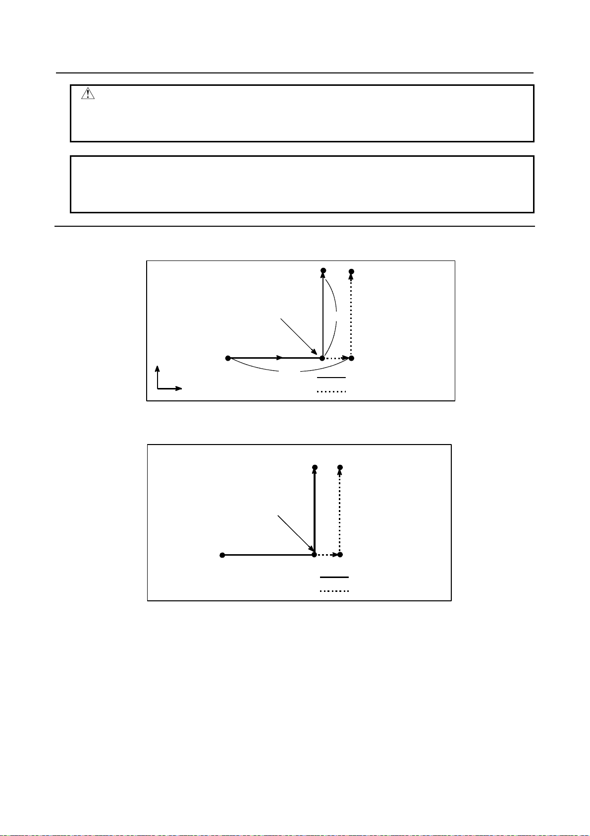
4.INTERPOLATION FUNCTIONS PROGRAMMING B-64554EN/01
A
A
CAUTION
Disable feedrate override, dry run, and automatic acceleration/deceleration
(however, these become available by setting bit 7 (SKF) of parameter No.6200
to 1.), allowing for an error in the position of the tool when a skip signal is input.
NOTE
If G33 command is issued while tool radius compensation is applied, an alarm
PS0035 is displayed. Cancel the tool radius compensation with the G40
command before the G33 command is specified.
Example
- The next block to G33 is an incremental programming
G33 G91 X100.0 F100;
Y50.0;
Skip signal is input here
Y
100.0
X
Fig. 4.5 (a) The next block is an incremental programming
50.0
ctual motion
Motion without skip signal
- The next block to G33 is an absolute programming for 1 axis
G33 G90 X200.0 F100;
Y100.0;
Skip signal is input here
Fig. 4.5 (b) The next block is an absolute programming for 1 axis
Y100.0
X200.0
ctual motion
Motion without skip signal
- 34 -
Page 59

B-64554EN/01 PROGRAMMING 4.INTERPOLATION FUNCTIONS
A
- The next block to G33 is an absolute programming for 2 axes
G33 G90 X200.0 F100;
X300.0 Y100.0;
Y
Skip signal is input here
100
(300,100)
ctual motion
Motion without skip signal
100 200 300
Fig. 4.5 (c) The next block is an absolute programming for 2 axes
X
4.6 MULTI-STEP SKIP (G33)
In a block specifying P1 to P4 after G33, the multi-step skip function stores coordinates in a custom
macro variable when a skip signal (4-point or 8-point ; 8-point when a high-speed skip signal is used) is
turned on. In the block where Q1 to Q4 are specified after G04, dwell can be skipped when skip signals
(four or eight signals, or eight signals when high-speed skip signals are used) are input.
A skip signal from equipment such as a fixed-dimension size measuring instrument can be used to skip
programs being executed.
For the usage of this function, refer to the manual supplied by the machine tool builder.
Format
Move command
_ F_ P_ ;
IP
G33
IP_ : End point
F_ : Feedrate
P_ : P1 to P4
Dwell
G04X(P)_ (Q_ );
X(P)_ : Dwell time
Q_ : Q1 to Q4
Explanation
Multi-step skip is caused by specifying P1, P2, P3, or P4 in a G33 block. For an explanation of selecting
(P1, P2, P3, or P4), refer to the manual supplied by the machine tool builder.
Specifying Q1, Q2, Q3, or Q4 in G04 (dwell command) enables dwell skip in a similar way to specifying
G33. A skip may occur even if Q is not specified. For an explanation of selecting (Q1, Q2, Q3, or Q4),
refer to the manual supplied by the machine tool builder.
- Correspondence to skip signals
Parameters Nos. 6202 to 6205 can be used to specify whether the 4-point or 8-point skip signal is used
(when a high-speed skip signal is used). Specification is not limited to one-to-one correspondence. It is
possible to specify that one skip signal correspond to two or more Pn's or Qn's (n=1, 2, 3, 4). Also, bits 0
(DS1) and 7 (DS8) parameter No.6206 can be used to specify dwell.
- 35 -
Page 60

4.INTERPOLATION FUNCTIONS PROGRAMMING B-64554EN/01
CAUTION
Dwell is not skipped when Qn is not specified and bits 0 (DS1) and 7 (DS8)
parameter No.6206 are not set.
4.7 HIGH-SPEED SKIP SIGNAL (G33)
The skip function operates based on a high-speed skip signal (connected directly to the NC; not via the
PMC) instead of an ordinary skip signal. In this case, up to eight signals can be input.
Delay and error of skip signal input is 0 - 2 msec at the NC side (not considering those at the PMC side).
This high-speed skip signal input function keeps this value to 0.1 msec or less, thus allowing high
precision measurement.
For details, refer to the appropriate manual supplied from the machine tool builder.
Format
G33 IP ;
G33; One-shot G code (If is effective only in the block in which it is specified)
4.8 SKIP POSITION MACRO VARIABLE IMPROVEMENT
Overview
The macro variables #100151 to #100157 (#5061 to #5067) for reading the skip position when executing
the skip command (G33) is improved.
By setting bit 7 (SKM) of parameter No. 6007 to 1, it is possible to read the skip position in the
workpiece coordinate system at the time a skip is made even if the workpiece coordinate system
setting/selection command is executed after the skip command is executed.
By setting bit 7 (SKM) of parameter No. 6007 to 0, it is possible to read the skip position that reflects the
workpiece coordinate system at the time it is read, as usual, if the workpiece coordinate system
setting/selection command is executed after the skip command is executed.
Macro variable
The following are the macro variables that can read the position at the time a skip is made even if the
workpiece coordinate system setting/selection command is executed after the skip command is executed,
by setting bit 7 (SKM) of parameter No. 6007 to 1.
System variable
number
#5061 to #5067 Skip position (workpiece coordinate system)
#100151 to #100157
#5421 to #5427 Skip position (workpiece coordinate system, detection unit)
#100701 to #100707
System variable
name
[#_ABSKP[n]] R
[#_SKPDTC[n]] R
Attribute Description
Note) Subscript n represents an axis number (1 to 7).
The numbers to the left can also be used.
Note) Subscript n represents an axis number (1 to 7).
Note) Subscript n represents an axis number (1 to 7).
The numbers to the left can also be used.
Note) Subscript n represents an axis number (1 to 7).
4.9 TORQUE LIMIT SKIP
Overview
Executing the move command following G33P99 (or G33P98) while overriding the torque limit*1 on the
servo motor enables cutting feed in to be performed in the same way as in linear interpolation (G01). If,
- 36 -
Page 61

B-64554EN/01 PROGRAMMING 4.INTERPOLATION FUNCTIONS
A
A
during the movement with this command, the torque of the servo motor reaches the torque limit value
(torque limit on the servo motor multiplied by the override) due to pressing or other causes or a skip
signal (including a high-speed skip signal) is input, any remaining move commands will be canceled, and
the next block is executed. (The operation of canceling any remaining move commands and executing the
next block is called a skip operation in the remainder of this document.)
It is possible to override the torque limit on the servo motor with the following command methods:
• Execute the torque limit override command in the PMC window.
Execute the torque limit command in the PMC window in advance. If the torque limit override command
is not set in advance, alarm PS0035 is issued. If the command falls outside the range, alarm PS0036 is
issued.
*1 : The torque limit on the servo motor is automatically set to a value conforming to the motor type
setting.
Format
G33 P98 α_ F_
G33 P99 α_ F_
G33 : Skip command (one-shot G code)
P98 : Performs a skip operation if the torque of the servo motor reaches the limit value.
P99 : Performs a skip operation if the torque of the servo motor reaches the limit value or if
a skip signal is input.
α : Axis address on any one axis
F : Feedrate
- Conditions for performing a skip operation
Condition
The torque limit value is reached. A skip operation is performed. A skip operation is performed.
A skip signal is input. No skip operation is performed. A skip operation is performed.
G33P98 G33P99
- Operation during a torque limit skip
(Example)
N1 G33 P99 Y400.0 F100.0 ;
N2 G01 X300.0 F500.0 ;
X
300.0
N2
: Machine stop position
B : Current position of the CNC when the
torque limit is reached
C : N1 command end point position
Command
200.0
Error amount
100.0
N1
100.0 200.0
B
300.0 400.0
C
Y
- 37 -
Page 62

4.INTERPOLATION FUNCTIONS PROGRAMMING B-64554EN/01
A torque limit skip presses a specified axis against a previously prepared part or other item while the
torque limit command is being executed on the servo motor, and then performs a skip operation when the
servo motor reaches the torque limit value. A skip operation is performed with the fact that the torque
limit value as detected in the servo motor is reached. It is, therefore, not necessary to input a skip signal
using a separate sensor or other device unlike with normal skip functions.
(1) At point A, the machine comes in contact with the object under measurement and stops. At this time,
because the torque limit value is not reached, no skip operation is performed, move commands are
continuously output, and the current position of the CNC is updated.
(2) Because move commands are output but the machine remains stopped, there occurs a difference
(error amount) between the current position of the CNC and the machine position, and torque is
applied to the servo motor.
(3) When the torque limit value is reached, a skip operation is performed at machine stop position, point
A, and the N2 command is executed. Assuming that the current position of the CNC when the torque
limit is reached is point B, the error amount during the torque limit skip is (A - B).
- Torque limit command
If, with the torque limit skip command, no torque limit command is issued from the PMC window, alarm
PS0035 is issued.
When no toque limit command is issued, the torque limit override value is either 0% or 100%.
A torque limit is to be specified as in the program example below.
(Program example)
O0012
:
Mxx (Specify a torque limit from the PMC via the window)
:
G33 P99 X200. F100.(Torque limit skip command)
:
G01 X100. F500.(Move command with the torque limit being still effective)
:
Myy (Cancel the torque limit from the PMC)
:
M30
- Positional deviation limit during the torque limit command
While the torque limit skip command is being executed, the positional deviation limit check with the
settings of parameters Nos. 1828 and 1829 is not performed. Instead, the positional deviation limit check
with the settings of parameter No. 6287 is performed. If the positional deviation exceeds the limit, alarm
SV0004 is issued and an instantaneous stop occurs.
- Custom macro variables
When the torque limit skip command is executed, the custom macro system variables #5061 to #5067 or
#100151 to #100157 (skip signal position) store the coordinate position assumed at the end of the skip. In
reality, there is a deviation due to the delay of the servo system between the machine position and the
current position of the CNC when a skip operation is executed. This deviation can be determined from the
positional deviation of the servo. By setting bit 2 (TSE) of parameter No. 6201, it is possible to select
whether or not the skip signal position to be stored in system variables should be compensated for with
the error (positional deviation) of the servo system.
- 38 -
Page 63

B-64554EN/01 PROGRAMMING 4.INTERPOLATION FUNCTIONS
y
Position during a skip operation
Current position of the CNC
Machine position
Coordinate origin
Position compensated for by
reflecting the delay
Position not reflecting the dela
Error
Stop point
NOTE
1 Specify only a single axis with the torque limit skip command. If no axis is
specified or an attempt is made to specify more than one, alarm PS0369 is
issued.
2 Do not issue the torque limit skip command in G41 or G42 mode. Otherwise,
alarm PS0035 is issued.
3 A torque limit arrival signal is output regardless of the torque limit skip command.
4 Do not issue the torque limit skip command for an axis being synchronized with
synchronous control.
5 Do not specify the torque limit skip command in a continuous block.
6 The higher the movement speed, the larger the error between the position at
which the machine stops and the position at which a skip is actually detected.
Also, the error increases as the speed is varied during movement. Do not vary
the speed with override and so on.
- 39 -
Page 64

5.FEED FUNCTIONS PROGRAMMING B-64554EN/01
5 FEED FUNCTIONS
Chapter 5, "FEED FUNCTIONS", consists of the following sections:
5.1 OVERVIEW .......................................................................................................................................40
5.2 RAPID TRAVERSE...........................................................................................................................41
5.3 CUTTING FEED................................................................................................................................42
5.4 CUTTING FEEDRATE CONTROL..................................................................................................43
5.5 FEEDRATE INSTRUCTION ON IMAGINARY CIRCLE FOR A ROTARY AXIS ......................47
5.6 DWELL...............................................................................................................................................50
5.1 OVERVIEW
The feed functions control the feedrate of the tool. The following two feed functions are available:
- Feed functions
1. Rapid traverse
When the positioning command (G00) is specified, the tool moves at a rapid traverse feedrate set in
the CNC (parameter No. 1420).
2. Cutting feed
The tool moves at a programmed cutting feedrate.
- Override
Override can be applied to a rapid traverse rate or cutting feedrate using the switch on the machine
operator's panel.
- Automatic acceleration/deceleration
To prevent a mechanical shock, acceleration/deceleration is automatically applied when the tool starts and
ends its movement (Fig. 5.1 (a)).
Rapid traverse rate
F
: Rapid traverse
F
R
0
T
T
R
Feedrate
FC
0
T
T
C
Fig. 5.1 (a) Automatic acceleration/deceleration (example)
R
C
R
rate
: Deceleration time
T
R
constant for rapid
traverse rate
Time
FC : Feedrate
: Acceleration/
T
C
deceleration time
constant for a
cutting feedrate
Time
- 40 -
Page 65

B-64554EN/01 PROGRAMMING 5.FEED FUNCTIONS
A
A
- Tool path in a cutting feed
When the movement direction changes between a specified block and the next block during cutting feed,
the tool path may be rounded because of the relationship between the time constant and feedrate (Fig. 5.1
(b)).
Y
Programmed path
ctual tool path
0
Fig. 5.1 (b) Example of tool path between two blocks
X
In circular interpolation, a radial error occurs (Fig. 5.1 (c)).
Y
0
Fig. 5.1 (c) Example of radial error in circular interpolation
Δr : Error
Programmed path
ctual tool path
r
X
The rounded-corner path shown in Fig. 5.1 (b) and the error shown in Fig. 5.1 (c) depend on the feedrate.
So, the feedrate needs to be controlled for the tool to move as programmed.
5.2 RAPID TRAVERSE
Format
G00 IP_ ;
G00 : G code (group 01) for positioning (rapid traverse)
IP_ : Dimension word for the end point
Explanation
The positioning command (G00) positions the tool by rapid traverse and punching is performed. In rapid
traverse, the next block is executed after the specified feedrate becomes 0 and the servo motor reaches a
certain range set by the machine tool builder (in-position check).
A rapid traverse rate is set for each axis by parameter No. 1420, so no rapid traverse feedrate need be
programmed.
The following overrides can be applied to a rapid traverse rate with the switch on the machine operator's
panel: 25, 50, 75, 100 %
5.2.1 Rapid Traverse Rate by F Command
Each axis rapid traverse rate of rapid traverse command (G00) are set independently to parameter by
machine tool builders.
Whereas, by setting bit 0 (G0F) of parameter No. 16050 to 1, the rapid traverse rate of X and Y axes to
rapid traverse command (G00) can be designated by F code. Refer to the manual issued by a machine tool
builder for this function.
- 41 -
Page 66

5.FEED FUNCTIONS PROGRAMMING B-64554EN/01
There are following specifications notices for this function.
(1) The feedrate specified by F code is the each axis rapid traverse rate of X and Y axes.
(2) 4-step rapid traverse override can be applied to the rapid traverse rate designated by F code, using
signals (ROV2, ROV1) from the machine side.
(3) When axial move of rapid traverse (G00) is specified in the DNC, memory and MDI modes, the
rapid traverse rate may not specified by F code or when the speed command is 0, an alarm (PS 0011)
occurs.
(4) In circular nibbling (G68), linear nibbling (G69) and nibbling by M function, the speed to nibbling
pitch after the first punch point corresponds to the rapid traverse rate preset by the parameter (No.
1420).
(5) F1-digit function for programmable rapid traverse override is ineffective.
(6) When the rapid traverse rate designated by F code exceeds the speed preset by a parameter (set by a
machine tool builder), it is clamped to the speed preset by the parameter (No. 1420).
5.2.2 F1-digit (Programmable Rapid Traverse Override)
By specifying one-digit number from 1 to 4 following address F, and override can be applied to the rapid
traverse rate in automatic operation.
F1-digit command Rapid traverse override
F1 100%
F2 75%
F3 50%
F4 25%
An override can be applied to the rapid traverse rate by the switch on the machine operator’s panel as well
as by F1-digit command in automatic operation.
Either rapid traverse override being set by the switch or the F1-digit command, whichever lower,
becomes effective.
NOTE
F1-digit (Programmable rapid traverse override) cannot be used together with
the Rapid traverse rate by F command.
5.3 CUTTING FEED
Overview
Feedrate of linear interpolation (G01), circular interpolation (G02, G03), etc. are commanded with
numbers after the F code.
In cutting feed, the next block is executed so that the feedrate change from the previous block is
minimized.
The feed of FANUC Series 0i-PD is performed at feed per minute always.
Format
Feed per minute
F_ ; Feedrate command (mm/min or inch/min)
- 42 -
Page 67

B-64554EN/01 PROGRAMMING 5.FEED FUNCTIONS
Explanation
- Direction of the cutting feedrate
Cutting feed is controlled so that the tangential feedrate is always set at a specified feedrate.
YY
Start
End point
point
F
Start
point
Linear interpolation
Fig. 5.3 (a) Tangential feedrate (F)
Center
X
Circular interpolation
F
End
X
- Feed per minute
An override from 0% to 254% (in 1% steps) can be applied to feed per minute with the switch on the
machine operator's panel. For detailed information, see the appropriate manual of the machine tool
builder.
Feed amount per minute
(mm/min or inch/ min)
Tool
ワーク
Fig. 5.3 (b) Feed per minute
CAUTION
Cutting feed is invalid for the turret axis (T–axis) and C–axis.
T–axis and C–axis commands, therefore, cannot be specified in linear
interpolation (G01) mode and circular interpolation (G02, G03) mode. However,
when bit 5 (CIP) of parameter No.16360 is set to 1, C–axis can be specified.
Reference
See Appendix D for range of feedrate command value.
5.4 CUTTING FEEDRATE CONTROL
Cutting feedrate can be controlled, as indicated in Table 5.4 (a).
- 43 -
Page 68

5.FEED FUNCTIONS PROGRAMMING B-64554EN/01
Table 5.4 (a) Cutting Feedrate Control
Function name G code Validity of G code Description
The tool is decelerated at the end point of a
block, then an in-position check is made.
Then the next block is executed.
The tool is decelerated at the end point of a
block, then an in-position check is made.
Then the next block is executed.
The tool is not decelerated at the end point
of a block, but the next block is executed.
When the tool moves along an inner corner
during tool radius compensation, override is
applied to the cutting feedrate to suppress
the amount of cutting per unit of time so
that a good surface finish can be produced.
The internal circular cutting feedrate is
changed.
Exact stop G09
Exact stop mode G61
Cutting mode G64
Automatic
Automatic
corner
override
override for
inner corners
Internal circular
cutting feedrate
change
G62
-
This function is valid for
specified blocks only.
Once specified, this
function is valid until G62,
G63, or G64 is specified.
Once specified, this
function is valid until G61,
G62, or G63 is specified.
Once specified, this
function is valid until G61,
G63, or G64 is specified.
This function is valid in
the tool radius
compensation mode,
regardless of the G code.
NOTE
1 The purpose of in-position check is to check that the servo motor has reached
within a specified range (specified with a parameter by the machine tool builder).
In-position check is not performed when bit 5 (NCI) of parameter No. 1601 is set
to 1.
2 Inner corner angle θ: 2° < θ ≤ α ≤ 178°
(α is a set value)
Workpiece
θ
Tool
Format
Exact stop G09 IP_ ;
Exact stop mode G61 ;
Cutting mode G64 ;
Automatic corner override G62 ;
5.4.1 Exact Stop (G09, G61), Cutting Mode (G64)
Explanation
The inter-block paths followed by the tool in the exact stop mode, and cutting mode are different (Fig.
5.4.1 (a)).
Y
(2)
(1)
0
In-position check
Tool path in the exact stop mode
Tool path in the cutting mode
X
- 44 -
Page 69

B-64554EN/01 PROGRAMMING 5.FEED FUNCTIONS
Fig. 5.4.1 (a) Example of tool paths from block (1) to block (2)
CAUTION
The cutting mode (G64 mode) is set at power-on or system clear.
5.4.2 Automatic Corner Override
When tool radius compensation is performed, the movement of the tool is automatically decelerated at an
inner corner and internal circular area. This reduces the load on the tool and produces a smoothly
machined surface.
5.4.2.1 Automatic override for inner corners (G62)
Explanation
- Override condition
When G62 is specified, and the tool path with tool radius compensation applied forms an inner corner, the
feedrate is automatically overridden at both ends of the corner.
There are four types of inner corners (Fig. 5.4.2 (a)).
2°≤θ≤θp≤178° in Fig. 5.4.2 (a) is a value set with parameter No. 1711. When θ is approximately equal to
θp, the inner corner is determined with an error of 0.001° or less.
: Tool
1. Straight line-straight line 2. Straight line-arc
: Programmed path
: Tool center path
θ
3. Arc-straight line 4. Arc-arc
θ
Fig. 5.4.2 (a) Inner corner
θ
θ
- Override range
When a corner is determined to be an inner corner, the feedrate is overridden before and after the inner
corner. The distances Ls and Le, where the feedrate is overridden, are distances from points on the tool
center path to the corner (Fig. 5.4.2 (b), Fig. 5.4.2 (c), Fig. 5.4.2 (d)). Ls and Le are set with parameters
Nos. 1713 and 1714.
Programmed path
Le
a
Tool center path
The feedrate is overridden from point a to point b.
Fig. 5.4.2 (b) Override Range (Straight Line to Straight Line)
Ls
- 45 -
b
Page 70

5.FEED FUNCTIONS PROGRAMMING B-64554EN/01
p
×
When a programmed path consists of two arcs, the feedrate is overridden if the start and end points are in
the same quadrant or in adjacent quadrants (Fig. 5.4.2 (c)).
Programmed path
Tool center path
The feedrate is overridden from
Fig. 5.4.2 (c) Override Range (Arc to Arc)
oint a to b.
Regarding program (2) of an arc, the feedrate is overridden from point a to point b and from point c to
point d (Fig. 5.4.2 (d)).
Programmed path
a
Ls Le
c
Tool
Fig. 5.4.2 (d) Override Range (Straight Line to Arc, Arc to Straight Line)
LsLe
b
(2)
Tool center path
- Override value
An override value is set with parameter No. 1712. An override value is valid even for dry run.
In the feed per minute mode, the actual feedrate is as follows:
=F
override) (feedratecorners)inner for override (automatic
Limitation
- Acceleration/deceleration before interpolation
Override for inner corners is disabled during acceleration/deceleration before interpolation.
- Start-up/G41, G42
Override for inner corners is disabled if the corner is preceded by a start-up block or followed by a block
including G41 or G42.
- Offset
Override for inner corners is not performed if the offset is zero.
- 46 -
Page 71
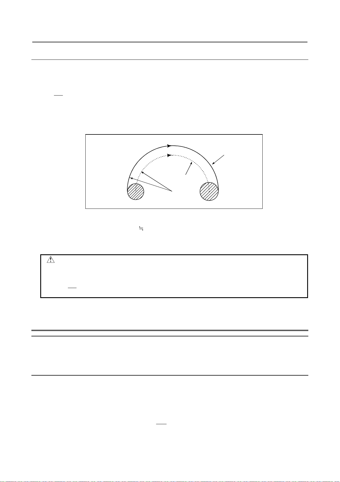
B-64554EN/01 PROGRAMMING 5.FEED FUNCTIONS
Δ
5.4.2.2 Internal circular cutting feedrate change
For internally offset circular cutting, the feedrate on a programmed path is set to a specified feedrate (F)
by specifying the circular cutting feedrate with respect to F, as indicated below (Fig. 5.4.2 (e)). This
function is valid in the tool radius compensation mode, regardless of the G62 code.
Rc
F =
Rp
Rc : Tool center path radius
Rp : Programmed radius
It is also valid for the dry run and the one-digit F code feed command.
Programmed
Tool center
Rc
Rp
path
Fig. 5.4.2 (e) Internal circular cutting feedrate change
If Rc is much smaller than Rp, Rc/Rp
specified with parameter No. 1710. When Rc/Rp≤MDR, the feedrate of the tool is (F×MDR).
If parameter No. 1710 is 0, the minimum deceleration ratio (MDR) is at 100%.
0; the tool stops. A minimum deceleration ratio (MDR) is to be
CAUTION
When internal circular cutting must be performed together with override for inner
corners, the feedrate of the tool is as follows:
Rc
F
override) (feedratecorners)inner for the (override ×××
Rp
5.5 FEEDRATE INSTRUCTION ON IMAGINARY CIRCLE FOR
A ROTARY AXIS
Overview
For the feedrate instruction on imaginary circle for a rotary axis, a circle with the radius specified with
parameter No. 1465 (which is referred to as an imaginary circle) is considered, and the feedrate of the
rotary axis is set to the feedrate on its circumference.
Explanation
- Cutting feedrate
Conventional method
Usually, the feedrate of a rotary axis is set to the rotation feedrate (deg/mm).
Feedrate of liner axis(X axis)
X
×=
FF
()
L
minmmX
/
- 47 -
Page 72

5.FEED FUNCTIONS PROGRAMMING B-64554EN/01
Δ
Δ
Δ
′
Feedrate of rotary axis(C axis)
Synthetic movement distance
Movement time
T =
L
F
C
×=
FF
()
L
)(min
mindegC
/
2222
CZYXL
Δ+Δ+Δ+Δ=
()
mm
Feedrate instruction on imaginary circle of a rotary axis
For the feedrate instruction on imaginary circle for a rotary axis, the feedrate of the rotary axis is set to
the movement feedrate on an imaginary circle with the radius specified with parameter No. 1465.
By setting the imaginary radius to 0, the rotary axis can be excluded from feedrate calculation.
Imaginary
radius
Feedrate of liner axis(X axis)
Feedrate of rotary axis(C axis)
Synthetic movement distance
Movement time
Rotary axis feedrate
Y
Program example
N1G91G01X10.F10.
N2C10.
N2
C
N1
FF
FF
′
X
Imaginary circle
X
×=
()
minmmX
/
′
L
C
×=
()
mindegC
/
′
L
π
⎛
222
ZYXL
+Δ+Δ+Δ=
⎜
⎝
L
′
=
T
lC : imaginary radius(parameter No.1465)
()
min
F
C
180
2
Cl
Δ××
⎞
⎟
()
mm
⎠
For the feedrate instruction on imaginary circle for a rotary axis, due to the difference in how to determine
the movement distance, if a particularly small value is set for the imaginary radius, the movement on the
axis will be fast. Pay careful attention to the input to the parameter.
The cutting feedrate is clamped on the basis of the maximum cutting feedrate parameter for each axis
No.1430 and the feedrate of the actual axis (data before this function is converted). It is, therefore,
possible to specify a command with a feedrate greater than the setting of the maximum cutting feedrate by
setting a large value as the imaginary radius parameter No. 1465. By setting a small value as an imaginary
radius, the cutting feedrate is clamped at the feedrate less than the setting of the maximum cutting
feedrate.
The feedrate instruction on imaginary circle for a rotary axis is also effective to a dry run.
- AI Advanced Preview Control
AI advanced preview control is performed on the movement feedrate on an imaginary circle. The
movement feedrate may, therefore, not be the feedrate for the calculation in the feedrate instruction on
imaginary circle for a rotary axis if the feedrate is changed with the feedrate control of AI advanced
preview control. The feedrate during AI advanced preview control is clamped with parameter No.1432. If
parameter No. 8465 is not 0, it is also clamped with parameter No. 8465.
- 48 -
Page 73

B-64554EN/01 PROGRAMMING 5.FEED FUNCTIONS
- 0mm in imaginary radius
When an imaginary radius is assumed 0mm, synthesized distance is as follows because the movement
distance of a rotary axis becomes 0mm.
′
222
ZYXL Δ+Δ+Δ=
A movement feedrate of a linear axis can be instruction feedrate F by excluding feedrate element of a
rotary axis.
Moreover, it moves at the maximum cutting feedrate in case of this setting and instruction only in a rotary
axis.
Examples
When the following block is instructed on IS-B,
G91 G01 C10. F10. ;
The calculation is as follows, when 10.000(10mm) is set in an imaginary radius(parameter No.1465).
C
180
min/
7453292.1
10
Δ××
⎞
⎟
⎠
×=
7453292.1
minmm
π
⎛
′
L
=
⎜
⎝
F
10
()
mmC
′
L
′
T
=
=
F
2
Bl
=
10
)/(
π
⎛
⎜
⎜
⎝
)(
deg
⋅⋅⋅
⋅⋅⋅
)(
mm
mm
)(
180
××
1010
2957795.57
Therefore, the movement time becomes about 10.472(sec), and the rotation feedrate becomes about
57.296(deg/min). The feedrate on 10.000mm in an imaginary radius becomes 10.000mm/min at
instruction feedrate in Fig. 5.5 (a).
The calculation is as follows, when 36.000(36mm) is set in an imaginary radius(parameter No.1465).
2
π
π
⎛
′
L
=
⎜
⎝
F
10
()
′
L
′
T
=
=
F
180
/
minmmC
Bl
Δ××
C
×=
28318530.6
28318530.6
10
⎛
⎞
⎜
=
⎟
⎜
⎠
⎝
10
)(
deg
⋅⋅⋅
)(
mm
)/(
minmm
××
1036
180
9154943.15
⋅⋅⋅
)(
mm
Therefore, the movement time becomes about 37.700(sec), and the rotation feedrate becomes about
15.915(deg/min). The feedrate on 36.000mm in an imaginary radius becomes 10.000mm/min at
instruction feedrate in Fig. 5.5 (a).
2
⎞
)()(
degmm
⎟
⎟
⎠
2
⎞
)()(
degmm
⎟
⎟
⎠
Rotation feedrate when
10mm setting.:(1)
7453292.1
⋅⋅⋅=
mindeg
4719755.1017453292.0
28318530.6
⋅⋅⋅=
)/(
mindeg
6991118.37628318530.0
⋅⋅⋅=
)(
mm
)/(
⋅⋅⋅=⋅⋅⋅=
)()(
secmin
⋅⋅⋅=
)(
mm
⋅⋅⋅=⋅⋅⋅=
)()(
secmin
Instruction feedrate
F=10mm/min
Rotation feedrate when
36mm setting.:(2)
10mm
36mm
- 49 -
Page 74

5.FEED FUNCTIONS PROGRAMMING B-64554EN/01
Fig. 5.5 (a)
Limitation
This function corresponds only the linear interpolation(G01).
However, it doesn't correspond to the following functions.
• Normal direction control
• Axis control by PMC
NOTE
1 When the bit 0 (ROTx) of parameter No. 1006 and the bit 0 (RFDx) of parameter
No. 1408 are 1, this function becomes effective.
2 The bit 0 (RFDx) of parameter No. 1408 and an imaginary radius (parameter
No.1465) of this function can be rewriting by the programmable parameter
input(G10).
3 It moves at the maximum cutting feedrate when this function effectively and sets
0 in an imaginary radius (parameter No.1465) and it instructs only a rotary axis.
4 Note setting bit 0 (RFDx) of parameter No. 1408 and an imaginary radius
(parameter No.1465) enough. Especially, a movement of axis quickens
compared with this function unused when small value is set to an imaginary
radius.
5 In this function, the same value as the parameter value (No.1408, No.1465) of a
master axis is used with a slave axis, when it uses axis synchronous control.
5.6 DWELL
Format
G04 X_; or G04 P_;
X_ : Specify a time (decimal point permitted)
P_ : Specify a time (decimal point not permitted)
Explanation
By specifying a dwell, the execution of the next block is delayed by the specified time. (Dwell per
second)
Table 5.6 (a) Command value range of the dwell time (Command by X)
Increment system Command value range Dwell time unit
IS-A 0.01 to 999999.99
IS-B 0.001 to 99999.999
Table 5.6 (b) Command value range of the dwell time (Command by P)
Increment system Command value range Dwell time unit
IS-A 1 to 99999999 0.01 s
IS-B 1 to 99999999 0.001 s
In the case of dwell per second, the specification unit for dwell time specified with P can be fixed at 0.001
second by setting bit 7 (DWT) of parameter No. 1015 to 1.
s
- 50 -
Page 75

B-64554EN/01 PROGRAMMING 5.FEED FUNCTIONS
NOTE
1 When X, or P is specified without a decimal point, the specification unit depends
on the increment system of the X-axis, and it does not depend on inch/metric
input.
2 When P is specified, bit 7 (IPR) of parameter No. 1004 exercises no influence.
While dwell is being executed, “1” is set for diagnosis display No. 0002.
Specify dwell also to make an exact check in the cutting mode (G64 mode).
If the specification of P and X is omitted, an exact stop occurs.
Diagnosis display
2 Dwell execution status
While dwell is being executed, “1” is displayed.
- 51 -
Page 76

6.REFERENCE POSITION PROGRAMMING B-64554EN/01
6 REFERENCE POSITION
A CNC machine tool has a special position where, generally, the tool is exchanged or the coordinate
system is set, as described later. This position is referred to as a reference position.
Chapter 6, "REFERENCE POSITION", consists of the following sections:
6.1 REFERENCE POSITION RETURN..................................................................................................52
6.1 REFERENCE POSITION RETURN
Overview
- Reference position
The reference position is a fixed position on a machine tool to which the tool can easily be moved by the
reference position return function.
When setting a workpiece to be machined to general turret punch press, the workpiece is held by the
workpiece holders after positioning it by applying the end face of the workpiece to the end locator and
workpiece holders mounted on the machine as illustrated below.
Face B
Workpiece
Y
Workpiece holderEnd locator
Fase B
End locator
Apply face A to workpiece holder.
Workpiece
Face A
Apply face B to the end locator.
Workpiece
Face A
Workpiece holder
X
- 52 -
Page 77

B-64554EN/01 PROGRAMMING 6.REFERENCE POSITION
A
A
Generally, the distance between the reference position and the end locator as well as the distance between
the reference position and the workpiece holders are intrinsically determined according to machines, and
they are separated from each other by a fixed distance.
Distance between reference position
and workpiece holder is intrinsicall y
determined according to machines.
Reference position
End locator
The distance between the reference
positionand the end locator is
intrinsically determined acc ording to
machines.
Workpiece holder
For example, if the start point is at the reference position and the point located at the left lower side of the
workpiece is presumed as the zero point of the workpiece coordinate system. The tool position at the start
point can be taught to NC as a position in the workpiece coordinate system by giving the following
command at the initial stage of programming.
G92X xR Y yR;
where, x
y
R : Distance from end locator to reference position along X-axis
R : Distance from workpiece holder to reference position along Y-axis
- Reference position return
Tools are automatically moved to the reference position. When reference position return is completed, the
lamp for indicating the completion of return goes on.
Setting bit 0 (SZR) of parameter No.16205 allows specifying whether to pass through the intermediate
point or not when the axis is returned to reference position.
utomatic reference position return
A→R
Reference position
R (
)
Start position for reference position return
(
)
- 53 -
Page 78

6.REFERENCE POSITION PROGRAMMING B-64554EN/01
A
A
utomatic reference position return A→Intermediate posit io n→R
Intermediate
(Start position for reference position
R (Reference position)
Format
- Return to the reference position without passing through the intermediate
point
G28_; Reference position return
- Return to the reference position via the intermediate point
G28 IP_; Reference position return
IP : Specify the intermediate position in the absolute coordinate system.
(absolute/incremental programming)
Explanation
- Return to the reference position without passing through the intermediate
point (G28)
Reference positions are performed at the rapid traverse rate of each axis.
Therefore, for safety, the compensation functions, such as the tool radius compensation, should be
cancelled before executing this command.
(Example)
G28 M30 ;
- Return to the reference position via the intermediate point
Positioning to the intermediate or reference positions are performed at the rapid traverse rate of each axis.
Therefore, for safety, the compensation functions, such as the tool radius compensation, should be
cancelled before executing this command.
(Example)
G28 X100.0 Y150.0 ;
Limitation
- Status the machine lock being turned on
The lamp for indicating the completion of reference position return does not go on when the machine lock
is turned on, even when the tool has automatically returned to the reference position
- First return to the reference position after the power has been turned on
(without an absolute position detector)
When the G28 command is specified when manual return to the reference position has not been
performed after the power has been turned on, the movement from the intermediate point is the same as in
manual return to the reference position.
- 54 -
Page 79

B-64554EN/01 PROGRAMMING 6.REFERENCE POSITION
In this case, the tool moves in the direction for reference position return specified in parameter ZMIx (bit
5 of No. 1006).
- Lighting the lamp when the programmed position does not coincide with the
reference position
When the machine tool system is an inch system with metric input, the reference position return lamp
may also light up even if the programmed position is shifted from the reference position by 1μ. This is
because the least input increment of the machine tool system is smaller than its least command increment.
Reference item
- Manual reference position return
See III–3.1 MANUAL REFERENCE POSITION RETURN.
- 55 -
Page 80

7.COORDINATE SYSTEM PROGRAMMING B-64554EN/01
Y
7 COORDINATE SYSTEM
By teaching the CNC a desired tool position, the tool can be moved to the position. Such a tool position is
represented by coordinates in a coordinate system. Coordinates are specified using program axes.
When two program axes, the X-axis and Y-axis are used, coordinates are specified as follows:
X_Y_
This command is referred to as a dimension word.
• Tool position specified by X40.0Y50.0
Tool
50.0
40.0
X
Coordinates are specified in one of following three coordinate systems:
(1) Machine coordinate system
(2) Workpiece coordinate system
(3) Local coordinate system
The number of the axes of a coordinate system varies from one machine to another. So, in this manual, a
dimension word is represented as IP_.
7.1 MACHINE COORDINATE SYSTEM
The point that is specific to a machine and serves as the reference of the machine is referred to as the
machine zero point. A machine tool builder sets a machine zero point for each machine.
A coordinate system with a machine zero point set as its origin is referred to as a machine coordinate
system.
A machine coordinate system is set by performing manual reference position return after power-on (see
Section, “MANUAL REFERENCE POSITION RETURN”). A machine coordinate system, once set,
remains unchanged until the power is turned off.
The reference position is not always the origin of the machine coordinate system.
(See "Reference - Setting a machine coordinate system" described later.)
Format
(G90)G53 IP _ P1;
IP_ : Absolute command dimension word
P1 : Enables the high-speed G53 function.
- 56 -
Page 81

B-64554EN/01 PROGRAMMING 7.COORDINATE SYSTEM
Explanation
- Selecting a machine coordinate system (G53)
When a command is specified the position on a machine coordinate system, the tool moves to the position
by rapid traverse. G53, which is used to select a machine coordinate system, is a one-shot G code; that is,
it is valid only in the block in which it is specified on a machine coordinate system. Specify an absolute
command for G53. When an incremental command is specified, the G53 command is ignored. When the
tool is to be moved to a machine-specific position such as a tool change position, program the movement
in a machine coordinate system based on G53.
- High-speed G53 function
This function enables the inter-rapid traverse block overlap function between machine coordinate
selection command (G53) and positioning (rapid traverse) command (G00) blocks, thus making it
possible to execute the next rapid traverse command (G00) without decelerating to a stop at the end of the
machine coordinate selection command (G53). Therefore, high-speed positioning is available even when
the machine coordinate selection command (G53) is used.
Specifying P1 in a G53 block enables the high-speed G53 function.
Limitation
- Cancel of the compensation function
When the G53 command is specified, cancel the compensation functions such as the tool radius
compensation beforehand.
- G53 command immediately after power supply turning on
The Reference point by the manual Reference point return or G28 command should return once after
turning on the power supply because it should set the machine coordinate system before it instructs in
G53.
However, the operation is unnecessary for the machine with the absolute-position detector.
- Specification in the same block
Commands G50/G51 (Scaling), and G84/G85 (Rotation) cannot be specified in the same block where the
G53 command is specified.
Note
NOTE
G53 is a G code for disabling buffering.
Reference
- Setting a machine coordinate system
When manual reference position return is performed after power-on, a machine coordinate system is set
so that the reference position is at the coordinate values of (α, β) set using parameter No.1240.
Machine coordinate system
Machine zero point
β
α
Reference position
- 57 -
Page 82

7.COORDINATE SYSTEM PROGRAMMING B-64554EN/01
7.2 WORKPIECE COORDINATE SYSTEM
Overview
A coordinate system used for machining a workpiece is referred to as a workpiece coordinate system. A
workpiece coordinate system is to be set with the CNC beforehand (setting a workpiece coordinate
system).
A machining program sets a workpiece coordinate system (selecting a workpiece coordinate system).
A set workpiece coordinate system can be changed by shifting its origin (changing a workpiece
coordinate system).
7.2.1 Setting a Workpiece Coordinate System
A workpiece coordinate system can be set using one of three methods:
(1) Method using a workpiece coordinate system setting G code
A workpiece coordinate system is set by specifying a value in the program after a workpiece
coordinate system setting G code.
(2) Automatic setting
If bit 0 (ZPR) of parameter No. 1201 is set to 1, a workpiece coordinate sy stem is automatically set
when manual reference position return is performed. (See Section, “MANUAL REFERENCE
POSITION RETURN”.)
This function is, however, disabled when the workpiece coordinate system option is being used.
(3) Method using a workpiece coordinate system selection G code
Six workpiece coordinate systems can be set beforehand using the MDI unit. Program commands
G54 to G59 can be used to select the workpiece axis to be used. (See Subsection, “Displaying and
Setting the Workpiece Origin Offset Value”.)
When using an absolute command, establish the workpiece coordinate system in any of the above ways.
Format
- Setting a workpiece coordinate system
(G90) G92 IP_
Explanation
A workpiece coordinate system is set so that a point on the tool, such as the tool center, is at specified
coordinates.
Cutter compensation is cancelled temporarily with G92.
- 58 -
Page 83

B-64554EN/01 PROGRAMMING 7.COORDINATE SYSTEM
Example
Setting the coordinate system by the
G92 X25.2 Y23.0 ; command
Y
23.0
0
Meet the programming start
point with a center of the tool
and command G92 at the start
of program.
25.2
X
7.2.2 Selecting a Workpiece Coordinate System
The user can choose from set workpiece coordinate systems as described below. (For information about
the methods of setting, see Subsection, “Setting a Workpiece Coordinate System”.)
(1) Once a workpiece coordinate system is set by a workpiece coordinate system setting G code or by
automatic workpiece coordinate system setting, absolute commands indicate positions in the
workpiece coordinate system.
(2) Choosing from six workpiece coordinate systems set using the MDI unit
By specifying a G code from G54 to G59, one of the workpiece coordinate systems 1 to 6 can be
selected.
G54 : Workpiece coordinate system 1 G55 : Workpiece coordinate system 2
G56 : Workpiece coordinate system 3 G57 : Workpiece coordinate system 4
G58 : Workpiece coordinate system 5 G59 : Workpiece coordinate system 6
Workpiece coordinate sy stem 1 to 6 are established after reference position return after the power is
turned on. When the power is turned on, G54 coordinate system is selected.
When bit 2 (G92) of parameter No. 1202 is set to 1, executing the workpiece coordinate system setting
G92 code command results in the issue of an alarm PS0010. This is designed to prevent the user from
confusing coordinate systems.
Example
G90 G55 G00 X40.0 Y100.0 ;
Y
Workpiece coordinate system 2 (G55)
100.0
40.0
In this example, positioning is made to
positions (X=40.0, Y=100.0) in workpiece
coordinate system 2.
X
Fig. 7.2.2 (a)
- 59 -
Page 84

7.COORDINATE SYSTEM PROGRAMMING B-64554EN/01
7.2.3 Changing Workpiece Coordinate System
The six workpiece coordinate systems specified with G54 to G59 can be changed by changing an external
workpiece origin offset value or workpiece origin offset value.
Three methods are available to change an external workpiece origin offset value or workpiece origin
offset value.
(1) Inputting from the MDI unit (see Subsection, “Displaying and Setting the Workpiece Origin Offset
Value”.)
(2) Programming (using a programmable data input G code or a workpiece coordinate system setting G
code)
(3) Using the external data input function
An external workpiece origin offset value can be changed by input signal to CNC. Refer to machine
tool builder's manual for details.
Workpiece
coordinate system 1
(G54)
Workpiece
coordinate system 2
(G55)
Workpiece
coordinate syste m 3
(G56)
Workpiece
coordinate system 4
(G57)
ZOFS2
ZOFS1
EXOFS
Machine zero point
EXOFS : External workpiece origin offset value
ZOFS1 to ZOFS6 : Workpiece origin offset value
Fig. 7.2.3 (a) Changing an external workpiece o rigin offset value or workpiece origin offset value
ZOFS3
ZOFS6
ZOFS4
ZOFS5
Workpiece coordinate
system 5 (G58)
Workpiece coordinate
system 6 (G59)
Format
- Changing by inputting programmable data
G10 L2 Pp IP_;
p=0 : External workpiece origin offset value
p=1 to 6 : Workpiece origin offset value correspond to workpiece coordinate system 1 to 6
IP_ : For an absolute command, workpiece origin offset for each axis.
For an incremental command, value to be added to the set workpiece origin offset for
each axis (the result of addition becomes the new workpiece origin offset).
- Changing by setting a workpiece coordinate system
G92 IP_ ;
Explanation
- Changing by inputting programmable data
By specifying a programmable data input G code, the workpiece origin offset value can be changed for
each workpiece coordinate system.
- Changing by setting a workpiece coordinate system
By specifying a workpiece coordinate system setting G code, the workpiece coordinate system (selected
with a code from G54 to G59) is shifted to set a new workpiece coordinate system so that the current tool
position matches the specified coordinates (IP_).
Then, the amount of coordinate system shift is added to all the workpiece origin offset values. This means
that all the workpiece coordinate systems are shifted by the same amount.
- 60 -
Page 85

B-64554EN/01 PROGRAMMING 7.COORDINATE SYSTEM
A
CAUTION
When a coordinate system is set with workpiece coordinate system setting G92
code command after an external workpiece origin offset value is set, the
coordinate system is not affected by the external workpiece origin offset value.
When G92X100.0Y80.0; is specified, for example, the coordinate system having
its current tool reference position at X = 100.0 and Y = 80.0 is set.
Example
Y
Y’
G54 workpiece coordinate system
160
60
100
100
100
200
Tool position
X’
X
New workpiece coordinate system
Original workpiece coordinate system
If G92X100Y100; is commanded when the tool is positioned
at (200, 160) in G54 mode, workpiece coordinate system 1
(X' - Y') shifted by vector A is created.
7.2.4 Workpiece Coordinate System Preset (G92.1)
The workpiece coordinate system preset function presets a workpiece coordinate system shifted by
manual intervention to the pre-shift workpiece coordinate system. The latter system is displaced from the
machine zero point by a workpiece origin offset value.
There are two methods for using the workpiece coordinate system preset function. One method uses a
programmed command. The other uses MDI operations on the absolute position display screen, relative
position display screen, and overall position display screen (see Subsection, “Workpiece Coordinate
System Preset”).
Format
G92.1 IP 0 ;
IP 0 : Specifies axis addresses subject to the workpiece coordinate system preset
operation. Axes that are not specified are not subject to the preset operation.
Explanation
When manual reference position return operation is performed in the reset state, a workpiece coordinate
system is shifted by the workpiece origin offset value from the machine coordinate system zero point.
Suppose that the manual reference position return operation is performed when a workpiece coordinate
system is selected with G54. In this case, a workpiece coordinate system is automatically set which has its
origin displaced from the machine zero point by the G54 workpiece origin offset value; the distance from
the origin of the workpiece coordinate system to the reference position represents the current position in
the workpiece coordinate system.
- 61 -
Page 86

7.COORDINATE SYSTEM PROGRAMMING B-64554EN/01
A
G54 workpiece coordinate system
G54 workpiece
origin offset value
Machine zero point
Workpiece origin
Reference positi o n
Manual reference position return
If an absolute position detector is provided, the workpiece coordinate system automatically set at
power-up has its origin displaced from the machine zero point by the G54 workpiece origin offset value.
The machine position at the time of power-up is read from the absolute position detector and the current
position in the workpiece coordinate system is set by subtracting the G54 workpiece origin offset value
from this machine position. The workpiece coordinate system set by these operations is shifted from the
machine coordinate system using the commands and operations listed below.
(a) Move command executed in the machine lock state
(b) Movement by handle interruption
(c) Operation using the mirror image function
(d) Shifting the workpiece coordinate system by setting the local coordinate system or workpiece
coordinate system
In the case of (b) above, the workpiece coordinate system is shifted by the amount of handle interruption.
Po
mount of
movement during
handle interruption
Workpiece origin
offset value
G54 workpiece
coordinate system before
handle interruption
WZo
G54 workpiece
coordinate system after
handle interruption
Machine zero point
WZn
-
Pn
In the operation above, a workpiece coordinate system once shifted can be preset using G code (G92.1)
specification or MDI operation to a workpiece coordinate system displaced by a workpiece origin offset
value from the machine zero point.
Bit 3 (PPD) of parameter No. 3104 specifies whether to preset relative coordinates (RELATIVE) as well
as absolute coordinates.
When no workpiece coordinate system option (G54 to G59) is selected, the workpiece coordinate system
is preset to the coordinate system with its origin placed at the reference position.
Limitation
- Tool radius compensation
When using the workpiece coordinate system preset function, cancel compensation modes: Tool radius
compensation. If the function is executed without canceling these modes, compensation vectors are
cancelled.
- Prohibited modes
Do not use the workpiece coordinate system preset function when the scaling, coordinate system rotation
is set.
- 62 -
Page 87

B-64554EN/01 PROGRAMMING 7.COORDINATE SYSTEM
7.2.5 Automatic Coordinate System Setting
When bit 0 (ZPR) of parameter No. 1201 for automatic coordinate system setting is 1, a coordinate
system is automatically determined when manual reference position return is performed.
Once α and β are set with parameter No. 1250, a workpiece coordinate system is set upon reference
position return so that the base point on the tool holder or the tip of the basic tool is positioned at X = α
and Y = β.
This processing occurs as if the following are specified at the reference position:
G92Xα
This function cannot be used, however, when the workpiece coordinate system is applied.
Yβ;
7.3 LOCAL COORDINATE SYSTEM
When a program is created in a workpiece coordinate system, a child workpiece coordinate system can be
set for easier programming. Such a child coordinate system is referred to as a local coordinate system.
Format
G52 IP_; Setting the local coordinate system
:
G52 IP 0 ; Canceling of the local coordinate system
IP_ : Origin of the local coordinate system
Explanation
By specifying G52 IP_;, a local coordinate system can be set in all the workpiece coordinate systems
(G54 to G59). The origin of each local coordinate system is set at the position specified by IP_ in the
workpiece coordinate system.
Once a local coordinate system is established, the coordinates in the local coordinate system are used in
an axis shift command. The local coordinate system can be changed by specifying the G52 command with
the origin of a new local coordinate system in the workpiece coordinate system.
To cancel the local coordinate system or specify the coordinate value in the workpiece coordinate system,
match the origin of the local coordinate system with that of the workpiece coordinate system.
- 63 -
Page 88

7.COORDINATE SYSTEM PROGRAMMING B-64554EN/01
IP_
(Local coordinate system)
(G54: Workpiece coordinate system 1)
Machine coordinate system zero point
Reference position
G55
G56
G57
G58
(Machine coordinate system)
Fig. 7.3 (a) Setting the local coordinate system
IP_
(Local coordinate system)
(G59: Workpiece coordinate
system 6)
CAUTION
1 When ZCL (bit 2 of parameter No.1201) is set to 1 and an axis returns to the
reference position by the manual reference position return function, the origin of
the local coordinate system of the axis matches that of the workpiece coordinate
system. The same is true when the following command is issued:
G52α0;
α: Axis which returns to the reference position
2 The local coordinate system setting does not change the workpiece and machine
coordinate systems.
3 Whether the local coordinate system is canceled at reset depends on the
parameter setting. The local coordinate system is canceled when either bit 6
(CLR) of parameter No.3402 or bit 3 (RLC) of parameter No.1202 is set to 1
4 When a workpiece coordinate system is set with the G92 command, the local
coordinate system is canceled. However, the local coordinate system of an axis
for which no coordinate system is specified in a G92 block remains unchanged.
5 G52 cancels the offset temporarily in tool radius compensation.
6 The incremental programming after the G52 block is not regarded as the
incremental distance from the current tool position. This programming is
regarded the incremental distance from origin of the local coordinate system
specified.
However, When the bit 0 (LIP) of parameter No. 16201 is set to 1, the
incremental programming after the G52 block is regarded as the incremental
distance from the current tool position.
- 64 -
Page 89

B-64554EN/01 PROGRAMMING 7.COORDINATE SYSTEM
7.4 PLANE SELECTION
Select the planes for circular interpolation, tool radius compensation, and coordinate system rotation.
The following table lists G-codes and the planes selected by them.
Explanation
Table 7.4 (a) Plane selected by G code
G code Selected plane Xp Yp Zp
G17 Xp Yp plane
G18 Zp Xp plane
G19 Yp Zp plane
Xp, Yp, Zp are determined by the axis address appeared in the block in which G17, G18 or G19 is
commanded.
When an axis address is omitted in G17, G18 or G19 block, it is assumed that the addresses of basic three
axes are omitted.
Parameter No. 1022 is used to specify that an optional axis be parallel to the each axis of the X-, Y-, and
Z-axes as the basic three axes.
The plane is unchanged in the block in which G17, G18 or G19 is not commanded.
The movement instruction is irrelevant to the plane selection.
When the power is turned on or the CNC is reset, G17 (XY plane), G18 (ZX plane), or G19 (YZ plane) is
selected by bits 1 (G18) and 2 (G19) of parameter No. 3402).
Example
Plane selection when the X-axis is parallel with the U-axis.
G17 X_Y_ ; XY plane,
G17 U_Y_ ; UY plane
G18 X_Z_ ; ZX plane
X_Y_ ; Plane is unchanged (ZX plane)
G17 ; XY plane
G18 ; ZX plane
G17 U_ ; UY plane
G18Y_ ; ZX plane, Y axis moves regardless without any relation to the plane.
X-axis or an axis
parallel to it
Y-axis or an axis
parallel to it
Z-axis or an axis
parallel to it
- 65 -
Page 90
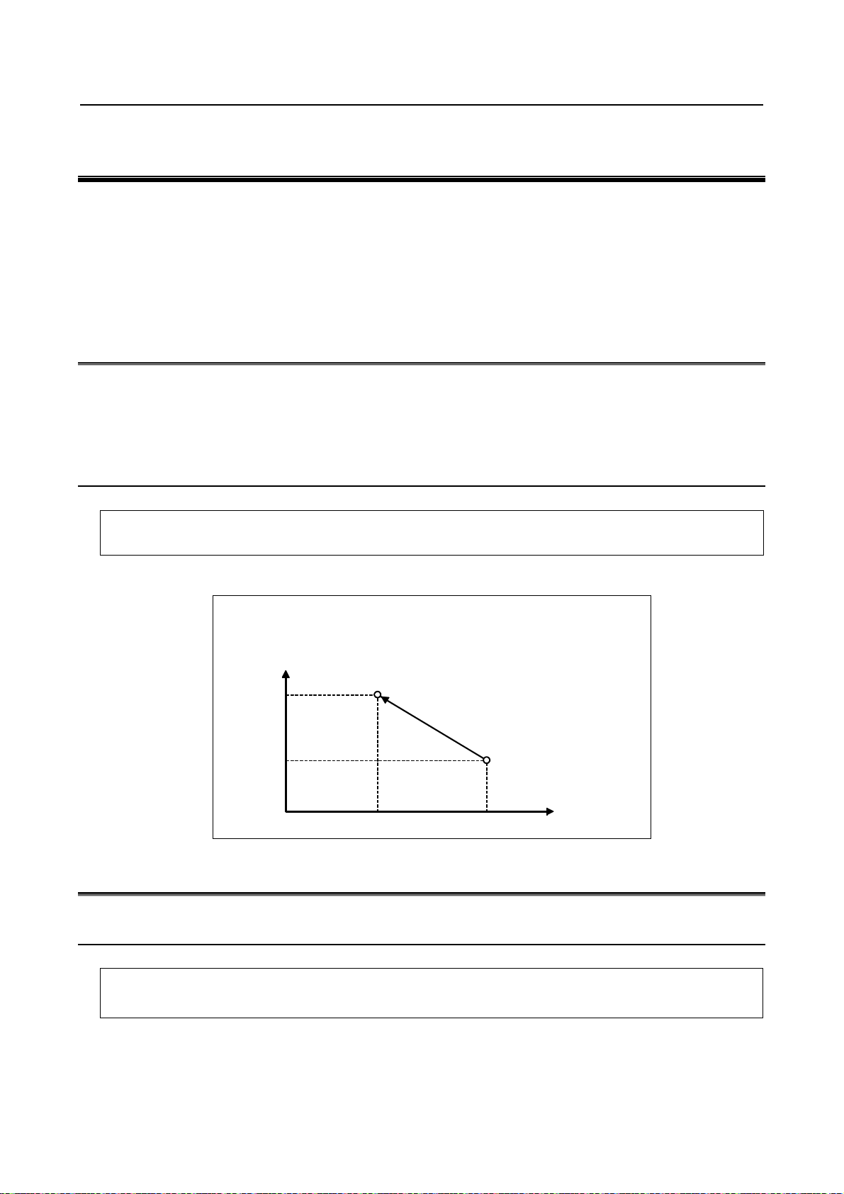
8. COORDINATE VALUE AND
A
DIMENSION
PROGRAMMING B-64554EN/01
8 COORDINATE VALUE AND DIMENSION
Chapter 8, "COORDINATE VALUE AND DIMENSION", consists of the following sections:
8.1 ABSOLUTE AND INCREMENTAL PROGRAMMING (G90, G91)..............................................66
8.2 INCH/METRIC CONVERSION (G20, G21).....................................................................................66
8.3 DECIMAL POINT PROGRAMMING ..............................................................................................69
8.1 ABSOLUTE AND INCREMENTAL PROGRAMMING (G90,
G91)
There are two ways to command travels of the tool; the absolute programming, and the incremental
programming. In the absolute programming, coordinate value of the end position is programmed. The
incremental programming is used to program the amount of a tool movement.
G90 and G91 are used to programming absolute or incremental programming, respectively.
Format
Absolute programming G90 IP_ ;
Incremental programming G91 IP_ ;
Example
G90 X40.0 Y70.0 ;
G91 X-60.0 Y40.0 ;
70.0
30.0
bsolute programming
Incremental programming
End point
40.0 100.0
Start point
X
8.2 INCH/METRIC CONVERSION (G20, G21)
Either inch or metric input (least input increment) can be selected by G code.
Format
G20 ; Inch input
G21 ; Metric input
This G code must be specified in an independent block before setting the coordinate system at the
beginning of the program. After the G code for inch/metric conversion is specified, the unit of input data
is switched to the least inch or metric input increment of increment system (see Section, “INCREMENT
- 66 -
Page 91

8.COORDINATE VALUE AND
B-64554EN/01 PROGRAMMING
SYSTEM”). The unit of data input for degrees remains unchanged. The unit systems for the following
values are changed after inch/metric conversion:
• Feedrate commanded by F code
• Positional command
• Workpiece origin offset value
• Tool compensation value
• Unit of scale for manual pulse generator
• Movement distance in incremental feed
• Some parameters
When the power is turned on, the G code is the same as that held before the power was turned off.
DIMENSION
WARNING
G20 and G21 must not be switched during a program.
NOTE
1 When the least input increment and the least command increment systems are
different, the maximum error is half of the least command increment. This error
is not accumulated.
2 The inch and metric input can also be switched using settings (see Subsection,
“Displaying and Entering Setting Data”).
3 If a function selected using bit 2 (IRF) of parameter No. 14000 or bit 0 (NIM) of
parameter No. 11222 is not used, be sure to perform inch/metric conversion at
the reference position (machine coordinate system origin).
Performing inch/metric conversion in the reference position (parameter No.
1240 is not 0)
Conventionally, inch/metric conversion must be performed at the machine coordinate system origin.
However, setting bit 2 (IRF) of parameter No. 14000 to 1 enables inch/metric conversion to be performed
in the reference position (parameter No. 1240).
If an attempt is made to perform inch/metric conversion when an axis with this function enabled is not in
the reference position, alarm PS5362, “CONVERT INCH/MM AT REF-POS” is issued to cancel the
attempt.
Before trying to perform inch/metric conversion, be sure to set the axis of interest to the reference
position, using the G28 command, for example.
In addition, if the workpiece coordinate system has been shifted from the machine coordinate system,
using the following commands or operations, bit 1 (CIM) of parameter No. 11222 can be used to select
whether to issue alarm PS1298 or to clear the offset.
• Move command issued with the machine locked
• Move command issued using a handle interrupt
• Mirror image-based operation
• Workpiece coordinate system shift caused by local coordinate system setting (G52) or workpiece
coordinate system setting (G92)
Switching conditions
Performing inch/metric conversion in any position other than the reference position requires satisfying all
of the following conditions. Failing to satisfy any of the conditions results in alarm PS1298, “ILLEGAL
INCH/METRIC CONVERSION” being issued
• Positioning or linear interpolation
• Tool radius compensation cancel
• Normal direction control cancel
- 67 -
Page 92

8. COORDINATE VALUE AND
DIMENSION
PROGRAMMING B-64554EN/01
• Scaling cancel
• Macro modal call cancel
• Coordinate system rotation mode off
In addition, performing inch/metric conversion in any position other than the reference position requires
the following options.
• Inch/metric conversion
• Workpiece coordinate system
Restrictions
When performing the following operations, make sure that the axis of interest is in the reference position
(machine coordinate system origin).
• Inch/metric conversion based on bit 2 (INI) of setting parameter No. 0
• Inch/metric conversion based on programmable parameter input (G10)
• Inch/metric conversion based on custom macro variable No. 3005
Performing inch/metric conversion in positions other than the reference
position
Setting bit 0 (NIM) of parameter No. 11222 enables inch/metric conversion to be performed even in
positions other than the reference position.
In addition, if the workpiece coordinate system has been shifted from the machine coordinate system,
using the following commands or operations, bit 1 (CIM) of parameter No. 11222 can be used to select
whether to issue alarm PS1298 or to clear the offset.
• Move command issued with the machine locked
• Move command issued using a handle interrupt
• Mirror image-based operation
• Workpiece coordinate system shift caused by local coordinate system setting (G52) or workpiece
coordinate system setting (G92)
If an axis is under any of the following controls, however, no automatic coordinate system conversion
based on this function can be carried out for the axis.
• Axis control by PMC
• Axis synchronous control (for slave axes when the master axis is a PMC axis)
Switching conditions
Performing inch/metric conversion in any position other than the reference position requires satisfying all
of the following conditions. Failing to satisfy any of the conditions results in alarm PS1298 being issued.
• Positioning or linear interpolation
• Tool radius compensation cancel
• Normal direction control cancel
• Scaling cancel
• Macro modal call cancel
• Coordinate system rotation mode off
In addition, performing inch/metric conversion in any position other than the reference position requires
the following options.
• Inch/metric conversion
• Workpiece coordinate system
• Workpiece coordinate system preset
- 68 -
Page 93

8.COORDINATE VALUE AND
B-64554EN/01 PROGRAMMING
DIMENSION
Restrictions
When performing the following operations, make sure that the axis of interest is in the reference position
(machine coordinate system origin).
• Inch/metric conversion based on bit 2 (INI) of setting parameter No. 0
• Inch/metric conversion based on programmable parameter input (G10)
• Inch/metric conversion based on custom macro variable No. 3005
8.3 DECIMAL POINT PROGRAMMING
Numerical values can be entered with a decimal point. A decimal point can be used when entering a
distance, time, or speed. Decimal points can be specified with the following addresses:
X, Y, Z, U, V, W, A, B, C, I, J, K, Q, R, F
Explanation
There are two types of decimal point notation: calculator-type notation and standard notation.
When calculator-type decimal notation is used, a value without decimal point is considered to be
specified in millimeters inch, or deg. When standard decimal notation is used, such a value is considered
to be specified in least input increments. Select either calculator-type or standard decimal notation by
using the bit 0 (DPI) of parameter No.3401.Values can be specified both with and without decimal point
in a single program.
Example
Program command
X1000
Command value without decimal point
X1000.0
Command value with decimal point
Pocket calculator type decimal
point programming
1000mm
Unit :mm
1000mm
Unit :mm
CAUTION
When specifying a dimension word for a command G code in a block, be sure to
place the dimension word after the command G code.
NOTE
1 A specified value less than the minimum unit is treated as described below.
Example 1)
When a value is specified directly at an address (in the case of 1/1000mm
IS-B)
X1.2345 ; Treated as X1.235
X-1.2345 ; Treated as X-1.234
Example 2)
When a value is assigned to a macro variable (in the case of 1/1000mm IS-B)
#100=1.2345;
X#100 ; Treated as X1.235
#100=-1.2345;
X#100 ; Treated as X-1.234
Standard type decimal point
programming
1mm
Unit : Least input increment (0.001mm)
1000mm
Unit :mm
- 69 -
Page 94

8. COORDINATE VALUE AND
DIMENSION
PROGRAMMING B-64554EN/01
NOTE
2 When more than eight digits are specified, an alarm occurs. If a value is entered
with a decimal point, the number of digits is also checked after the value is
converted to an integer according to the least input increment.
Examples:
X1.23456789;
Alarm PS0003, “TOO MANY DIGIT” occurs because more than eight digits
are specified.
X123456.7;
If the least input increment is 0.001 mm, the value is converted to integer
123456700. Because the integer has more than eight digits, an alarm
occurs.
- 70 -
Page 95

B-64554EN/01 PROGRAMMING 9.PRESS FUNCTION
9 PRESS FUNCTION
Chapter 9, "PRESS FUNCTION", consists of the following sections:
9.1 PUNCH FUNCTION (1-CYCLE PRESSING) ..................................................................................71
9.2 POSITIONING & PRESSING OFF (G70).........................................................................................73
9.3 NIBBLING FUNCTION ....................................................................................................................73
9.4 NIBBLING BY M FUNCTION .........................................................................................................82
9.5 EXTERNAL MOTION FUNCTION..................................................................................................86
9.1 PUNCH FUNCTION (1-CYCLE PRESSING)
This control sends a signal “Start press and punch” to the machine after moving a tool to the position
commanded in a predetermined block.
When the machine receives this signal, it starts pressing. As a result, punching is made on a workpiece by
the selected tool. After punching, the press motion stops, and a signal returns to the NC to indicate that
“punch has finished”.
Thus, NC proceeds to the execution of the next block. In this manner, punching on a workpiece by press
motion is executed by data transfer between the NC and the machine, and it is necessary to know the
blocks to be punched, in advance.
This description is made from the viewpoints of the NC side. Since details may differ depending upon the
machine tool builders, refer to the machine tool builder’s manual without fail.
NOTE
This section covers one-cycle punch only. For nibbling (punching by sequential
repeated press motion), refer to “9.3 NIBBLING FUNCTION”.
9.1.1 Block in which Punching is Made
Punching is made in a block where the X-axis or Y-axis is positioned at rapid traverse, in principle. In
other words, punching is not done in a block where the X-axis or Y-axis
is not positioned at rapid traverse. Blocks where punching is done are as follows:
(1) Block where X-axis or Y-axis is positioned in the positioning mode (G00)
CAUTION
If the same position as the present tool position is commanded by address X or
Y, positioning is not done, but punching is executed. (This is regarded as the
positioning command with movement amount 0)
G00G91X0; . . . Punching is made.
This applies to such a case that punching is done at the same position using a
different tool.
- 71 -
Page 96

9.PRESS FUNCTION PROGRAMMING B-64554EN/01
Tool 01 profile
Tool 02 profile
N711G00G90X50.0Y30.0T02;
N712X50.0Y30.0T01;
The punch profile at (50, 30) position is as shown below.
No punching is made in case of N712T01;, N712T01C50.01;
. . .
. . .
Punching is done using tool 02
Punching is made using tool 01
CAUTION
Punching is not done in T single block where the X-axis or Y-axis moves for tool
offset.
(2) Block where pattern function G26, G76, G77, G78, G79, G86, G87 or G89 was commanded
Punching is made after positioning to respective points on a pattern.
Punching is not done in the following cases, even if the block corresponds to (1) or (2).
(a) MDI mode is selected.
(b) M code is commanded.
(c) Blocks inserted between M code of workpiece clamp and M code of workpiece unclamp which
are employed for repositioning of workpiece.
(d) Block where positioning & punch off (G70) was commanded.
CAUTION
Punching is not done even in G00 mode if the block is irrespective of positioning
such as coordinate system setting (G92), local coordinate system setting (G52),
standard point command (G72), dwell (G04), etc.
- 72 -
Page 97

B-64554EN/01 PROGRAMMING 9.PRESS FUNCTION
9.2 POSITIONING & PRESSING OFF (G70)
Punching is made in a block where the X-axis or Y-axis if positioned at rapid traverse, in principle.
Command the following code, if it is not desired to punch a workpiece after positioning a tool to the
commanded position at rapid traverse.
G70X__Y__;
CAUTION
1 G70 is an one–shot G code.
2 Rapid traverse is made in a G70 block even if in G01, G02 or G03 mode.
9.3 NIBBLING FUNCTION
Nibbling means sequential repeated punching without stopping press motion.
Assume Tt be the time required for one-cycle press motion. The remaining time obtained by subtracting
punching time Tp from Tt (or, Ti = Tt – Tp) is the time allowable for positioning.
Flywheel
Position of tool
Crank mechanism
Tool f o r
punching
Upper dead
point
workpiece
Lower dead
point
Position
Time
Fig.9.3
Tp
Tt
Tt : One cycle in press motion
Tp : Processing time of press motion
Ti : Positioning time for the workpiece
Ti
The maximum distance (maximum pitch) which can be positioned in time Ti is limited by various
conditions, such as machine, servo motor, and others as well as time Ti.
In this NC, the maximum nibbling pitch determined by these conditions is preset as a parameter. On the
other hand, the nibbling pitch is commanded by a program. If the commanded pitch exceeds the
maximum pitch preset by the parameter, an alarm is produced.
Since this pitch can be specified directly, programming can be done, while taking the scallop into
consideration.
- 73 -
Page 98

9.PRESS FUNCTION PROGRAMMING B-64554EN/01
Scallop s
p
The relation between pitch p and scallop s is as shown below in case of linear
nibbling
2 ssdp −=
where d: Tool diameter
2
The following functions are prepared for nibbling.
Function Description
Punching at constant intervals
(distance) along the Circular arc for
Circular nibbling (G68)
Linear nibbling (G69)
Nibbling by M function
a specified angle.
G68 I r
Punching at constant intervals
(distance) along the straight line for
a specified distance.
G69 I l
M## ← M code of nibbling mode(
‥‥‥‥‥
‥‥‥‥‥ The route and the pitch are specified according to these
‥‥‥‥‥ command
M$$ ← M code of nibbling mode cancel
(
J θ K Δθ P d Q p
J θ P d Q p
d
Set value of parameter No.16183)
Set value of parameter No.16184)
#n
d
r
Δθ
l
p
θ
#2
#1
#2
#1
p
θ
d
#n
- 74 -
Page 99

B-64554EN/01 PROGRAMMING 9.PRESS FUNCTION
Δ
θ
θ
9.3.1 Circular Nibbling (G68)
Circular nibbling (G68) specifies punching at constant pitch (distance) on the circular arc with a start
point specified by G72 or the current tool position as the center of the circle.
Format
G68 I
r J θ K Δθ P d Q p
r : Radius of arc (Valid data range : 1 to 999999999)
Unit of data : Input unit (inch/mm)
-Should be specified by positive number.
: Angle formed between the first punch point and the + X axis
θ
(Valid data range : When the increment system is IS-B, −359999 to 359999)
Unit of data : minimum unit of data (deg)
-The counterclockwise direction is commanded by a positive number.
: Incremental angle from the first punch point to the least punch point
Δθ
(Valid data range : −999999999~999999999)
Unit of data : minimum unit of data (deg)
-Counterclockwise nibbling is made when this angle is commanded by a positive
number.
d : Tool diameter value (Valid data range : −999999999 to 999999999)
Unit of data : Input unit (inch/mm)
-Nibbling is made outside the arc when this value is positive, inside the arc when this
value is negative, and on the circumference when this value is 0.
-Actual tool path is the arc having radius r+d/2.
p :Pitch (Valid data range : 1 to 999999999)
Unit of data : Input unit (inch/mm)
-Should be specified by positive number.
-This pitch is specified as an arc length.
Nibbling is made at pitch p using a tool having diameter d, starting with the point which forms angle θ
with reference to the X-axis on the circumference having radius r, with the preset tool position or the
position specified by G72 being set as the circle center, to the point which forms angle θ + Δθ with
reference to the X-axis.
When θ>0, Δθ>0, and d>0
#1 to #n :Order of punch motion
#(n−1)
#n
#3
r
p
Center of circle
(Pattern base point)
#2
#1
d
+X
- 75 -
Page 100

9.PRESS FUNCTION PROGRAMMING B-64554EN/01
Example 1
N1111 G90 G00 X50. Y97.
N1112 G72 X50. Y100.
N1113 G68 I4. J−60. K90. P−1. Q0.8
Coordinates are expressed by IS-B
#1 to #9
:Order of punch motion in
N1113
:Path of tool
1.000
N1112
(50.000,100.000)
N1111:(50.000,97.000)
4.000
90°
−60°
#1:(51.750,96.969)
#2:(52.308,97.369)
0.800 → Actual pitch=0.785
#9:(53.031,101.750)
#8:(53.314,101.125)
#7:(53.470,100.457)
+X
#6:(53.493,99.771)
#5:(53.381,99.094)
#4:(53.139,98.452)
#3:(52.777,97.869)
- 76 -
 Loading...