

Page 1
Gibbs and Associates
323 Science Drive
Moorpark, CA 93021
(805) 523-0004
March, 1999
MILL/TURN
Page 2

Proprietary Notice
This document contains propriety information of Gibbs and Associates and is to be used only pursuant to and in conjunction with the license granted to the licensee with respect to the accompanying Gibbs and Associates licensed software. Except as expressly permitted in the license, no part of
this document may be reproduced, transmitted, transcribed, stored in a retrieval system, or translated
into any language or computer language, in any form or by any means, electronic, magnetic, optical,
chemical, manual or otherwise, without the prior expressed written permission from Gibbs and
Associates or a duly authorized representative thereof.
It is strongly advised that users carefully review the license in order to understand the rights and
obligations related to this licensed software and the accompanying documentation.
Use of the computer software and the user documentation has been provided pursuant to a Gibbs
and Associates licensing agreement.
© Copyright 1998 Gibbs and Associates, Inc.
All Rights Reserved
Acknowledgements:
Written by: Shannon McConville and Wil Gaffga
Thanks to Bill Gibbs, Alvaro Martins, Jeff Castanon, Bart Ehlers, Jeff Myers, Gary Esser, Michael
Kelley Charles Haden and Israel Klain for their input and assistance.
Special Thanks to Louise Burns for supplying the Clutch Basket tutorial part.
Trademarks:
Windows NT and Windows 95 are trademarks of Microsoft Corporation
Macintosh is a trademark of Apple Computers, Inc.
Printed in the United States of America
◆
Mill/Turn Manual GFK-1711
Page 3

Table of Contents
MILL TURN II
Introduction . . . . . . . . . . . . . . . . . . . . . . . . . . . . . . . . . . . . . . . . . . . . . . . . . . . . . . . . . . . . ii
Preferences . . . . . . . . . . . . . . . . . . . . . . . . . . . . . . . . . . . . . . . . . . . . . . . . . . . . . . . . . . . . . 2
Interface . . . . . . . . . . . . . . . . . . . . . . . . . . . . . . . . . . . . . . . . . . . . . . . . . . . . . . . . . . . . . . . 2
PART SETUP 4
Machine Definition Documents. . . . . . . . . . . . . . . . . . . . . . . . . . . . . . . . . . . . . . . . . . . . . . 4
Coordinate Systems . . . . . . . . . . . . . . . . . . . . . . . . . . . . . . . . . . . . . . . . . . . . . . . . . . . . . . 5
Geometry Creation . . . . . . . . . . . . . . . . . . . . . . . . . . . . . . . . . . . . . . . . . . . . . . . . . . . . . . 16
Tool Orientation . . . . . . . . . . . . . . . . . . . . . . . . . . . . . . . . . . . . . . . . . . . . . . . . . . . . . . . . 16
MACHINING OPERATIONS 19
Machining. . . . . . . . . . . . . . . . . . . . . . . . . . . . . . . . . . . . . . . . . . . . . . . . . . . . . . . . . . . . . 19
Y-axis & C-axis Interpolation . . . . . . . . . . . . . . . . . . . . . . . . . . . . . . . . . . . . . . . . . . . . . . 21
ROTARY MILLING & WRAPPING 23
MILL/TURN EXERCISES 26
Exercise 1 : Clutch Basket . . . . . . . . . . . . . . . . . . . . . . . . . . . . . . . . . . . . . . . . . . . . . . . . 26
Exercise 2 : Coupling . . . . . . . . . . . . . . . . . . . . . . . . . . . . . . . . . . . . . . . . . . . . . . . . . . . . 41
GFK-1711 T able of Contents
◆
i
Page 4
INTRODUCTION
The system provides for Mill/Turn capabilities when both the Mill module and Lathe module of the
software are present. When this is the case, the system will have an option to designate the machine
type as Mill/Turn, and the user can now apply any of the system's available milling machining
processes to a lathe part. All milling and turning functions are available for Mill/Turn parts.
Additional modules are available that increase the capabilities of Mill/Turn, most importantly the
Rotary Milling option which provides the ability to wrap any shape or toolpath around the C axis
using rotary axis interpolation.
The Mill/Turn functionality of the software provides capabilities for programming single spindle,
single turret lathes that have the capability of driving live tooling. The turret positions can drive live
tools such as endmills and drills which can be oriented along the Z axis, toward the chuck (face
machining), or along the X axis, toward the turret (OD machining). In order to perform milling
operations, the spindle must be changed from its normal function of spinning the part into a third
programmable axis, usually designated as the C axis. The Mill/Turn functionality allows users to
position the part by specifying angular rotations of the C axis.
Note: This symbol is used periodically in this manual to signify Mill/Turn functions that
are enhanced by the Advanced Mill module.
The following image is intended to clarify differences between different system modules and functions.
Mill/Turn allows the user to use a live mill tool with simple angle positions of the C-axis on the OD
or face of the part.
Rotary Mill allows the user to wrap geometry about the C-axis and allows continuous C-Axis rotation
when programming milling operations.
If the user’s machine has Y-axis capabilities any mill operation may be performed at any C-axis posi-
tion
TERMINOLOGY
Live Tool: When a live tool is used the lathe spindle stops rotating and engages C-axis rotary motion.
A milling tool is set to spin at a specified RPM.
Wrapped Geometry: A standard term for geometry that is drawn flat and wrapped or rotated around
the rotary axis.
ii
◆
Mill/Turn Manual GFK-1711
AM
Page 5
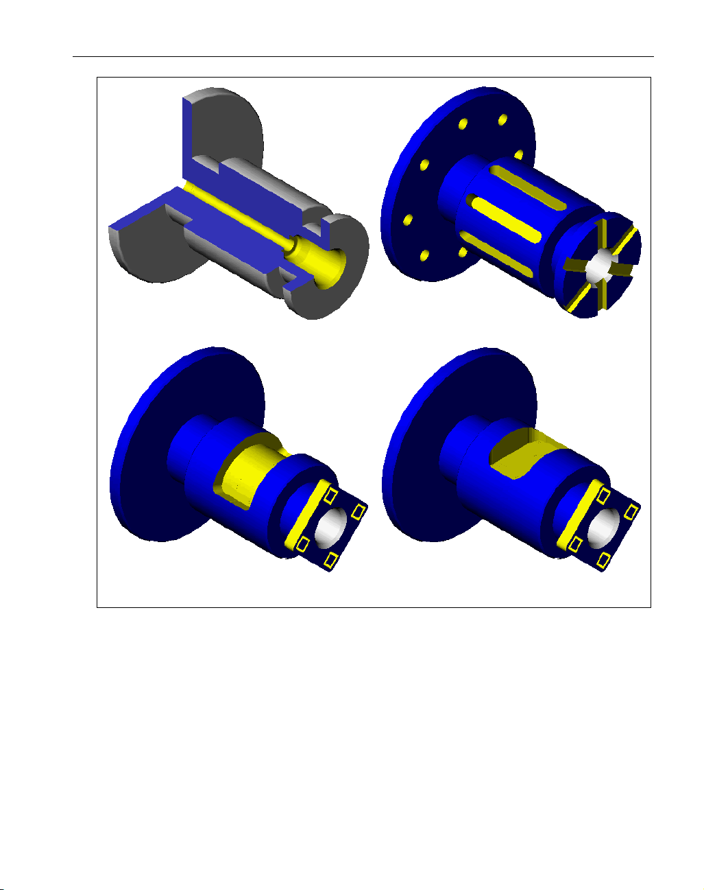
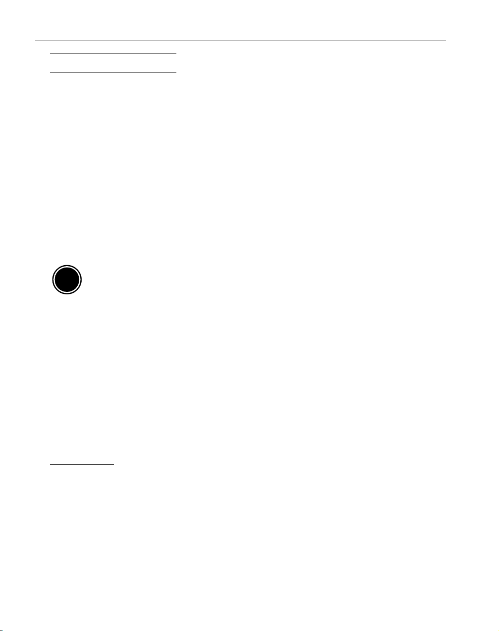
Figure 1: A comparison of capabilities in system modules.
1
GFK-1711 Mill/Turn
◆
Lathe module Mill/Turn capability
Rotary Mill Rotary Mill with Y-Axis capability
Page 6
PREFERENCES
Graphics preference: The Graphics Preference
which is accessed from the Preferences sub-
menu under the File menu contains an item
called Grid Brightness. This affects the con-
trast and brightness of the CS grid drawn on
the screen. The brightness can be adjusted by moving the slider. Clicking on the Apply Button in
the Graphics Preference Dialog will apply the changes.
INTERFACE
The system has three different levels of functionality, Level 0, Level 1 and Level 2, providing more
advanced features as the level number is increased. All levels are available to users regardless of the
specific options that are installed with the system, however certain items may not be accessible
depending on the options installed. In order to use the Mill/Turn functions the user must be working
with the Level 2 interface.
Each level makes slight changes to the interface. The Level 1 interface contains a 7 button Top level
palette, while the Level 2 interface is characterized by a 14 button Top Level palette and a taskbar.
The interface level is specified in the Interface Preferences accessed from the Preferences submenu
under the File menu.
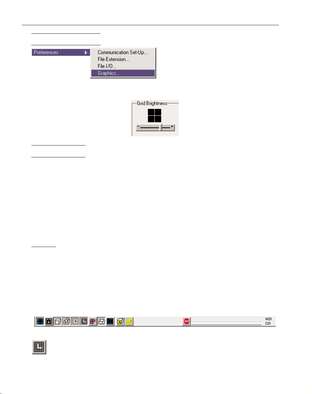
TASKBAR
When working with the Level 2 interface, there is a taskbar located along the top of the drawing
window, directly below the menu bar. The taskbar contains a series of buttons which affect the
drawing and selection of items in the drawing window. Each of the buttons has two states, depressed
(on) or raised (off). The taskbar also contains a progress bar and message display. The progress messages indicate the function the system is performing and the progress bar gives the status of the
function. The Stop button can be depressed to stop the current function. The current workgroup and
coordinate system are displayed next to the progress bar. Again, certain items may be unavailable
depending on the options installed with the system. There are two taskbar buttons which are used
specifically for Mill/Turn parts.
Show CS Grid Button: When it is turned on, (the button is depressed), the CS grid and axis
markers for the current Coordinate System will be drawn on the screen.
2
◆
Mill/Turn Manual GFK-1711
Page 7

Stock Cutaway: This button affects the cut part rendering function only. When turned on, the
stock used for the cut part rendering will have a quarter section cut out. This is useful when
rendering lathe parts which contain ID operations. When turned off, the stock used for cut
part rendering will be a full cylinder. When rendering Mill/Turn parts, it is recommended that Stock
Cutaway be turned off to ensure that OD milling operations are viewed in the cut part rendering
process.
Wrap Geometry: This button affects geometry creation. It is only available when the Rotary
Milling option is installed. The Rotary Milling function provides continuous C axis rotation
on milling operations, also referred to as wrapping. When this button is turned on, geometry
can be created and viewed radially, wrapped around the OD of the part. Rather than creating "flat"
geometry using XYZ coordinates, the system allows users to create radial geometry using XZC
coordinates, where X designates the radius or diameter. The user can either create flat geometry and
then wrap it or simply create geometry using radial values. Any geometry can be wrapped, including
lines, closed shapes and text. In order to create and view geometry radially, this button must be
depressed. Effectively, geometry will be wrapped on the OD of the part. In addition, the Rotary
Milling checkbox in the WG Info dialog must be checked. This issue will be discussed further in the
Rotary Milling section of this manual.
HOME VIEW
The Home View is an additional view available from the Trackball that is useful when working with
different coordinate systems. When selected, the system rotates the view of the part to a view normal (3D perpendicular) to the current coordinate system. The Home View always displays the part
with the positive depth axis projecting out of the screen, signified by the “+” at the center of the axis
markers. Using the part model on the trackball in the center of the View Control Palette allows the
user to get an idea of the positioning of the plane in 3D space relative to the overall part.
Figure 2: Home View
GEOMETRY COLOR SCHEME
The system uses colors to graphically differentiate between certain items drawn on the screen.
Additional meaning is added to the color scheme when working with multiple coordinate systems.
Blue and Yellow: Geometry drawn on the screen in either blue or yellow indicates that it is contained
in the current workgroup and based on the current coordinate system. The current coordinate system
is the coordinate system that is being worked in and is highlighted in the CS List Dialog.
Magenta: This color is added when working with multiple coordinate systems. Geometry drawn in
magenta indicates that the geometry is not based on the current coordinate system. Magenta geome-
3
GFK-1711 Mill/Turn
◆
Home View
Page 8
try can be selected, modified and used for machining operations. The color change merely indicates that the geometry was not created while working in the current coordinate system.
Gray: Geometry drawn in grey is contained in a background workgroup. It may or may not be based
on the current CS. Geometry in a background workgroup cannot be selected or modified.
Part Set-Up
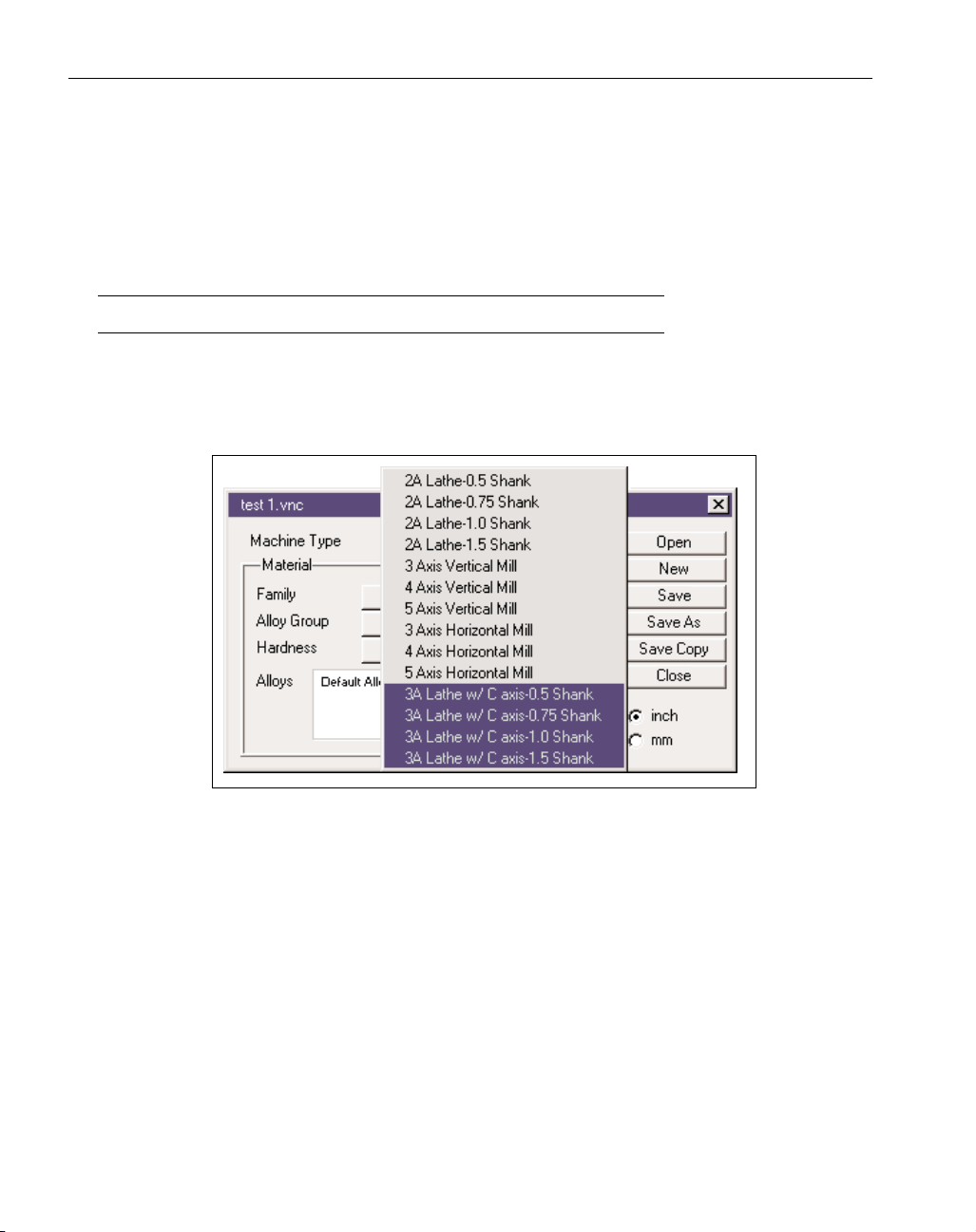
MACHINE DEFINITION DOCUMENTS
Setting up a mill turn part is very similar to that of a standard lathe part. The stock is designated in
the same manner and the options for designating clearance planes are identical to that for turning
parts. With both the Mill and Lathe modules installed, additional Machine Definition Documents
(MDD’s) will be available in the Machine Type pull-down menu in the Document Control Dialog.
The Mill/Turn MDD's are similar to Lathe MDD's in that different shank sizes are available.
Figure 3: New Machine Definition Documents (MDD’s) for Mill/Turn
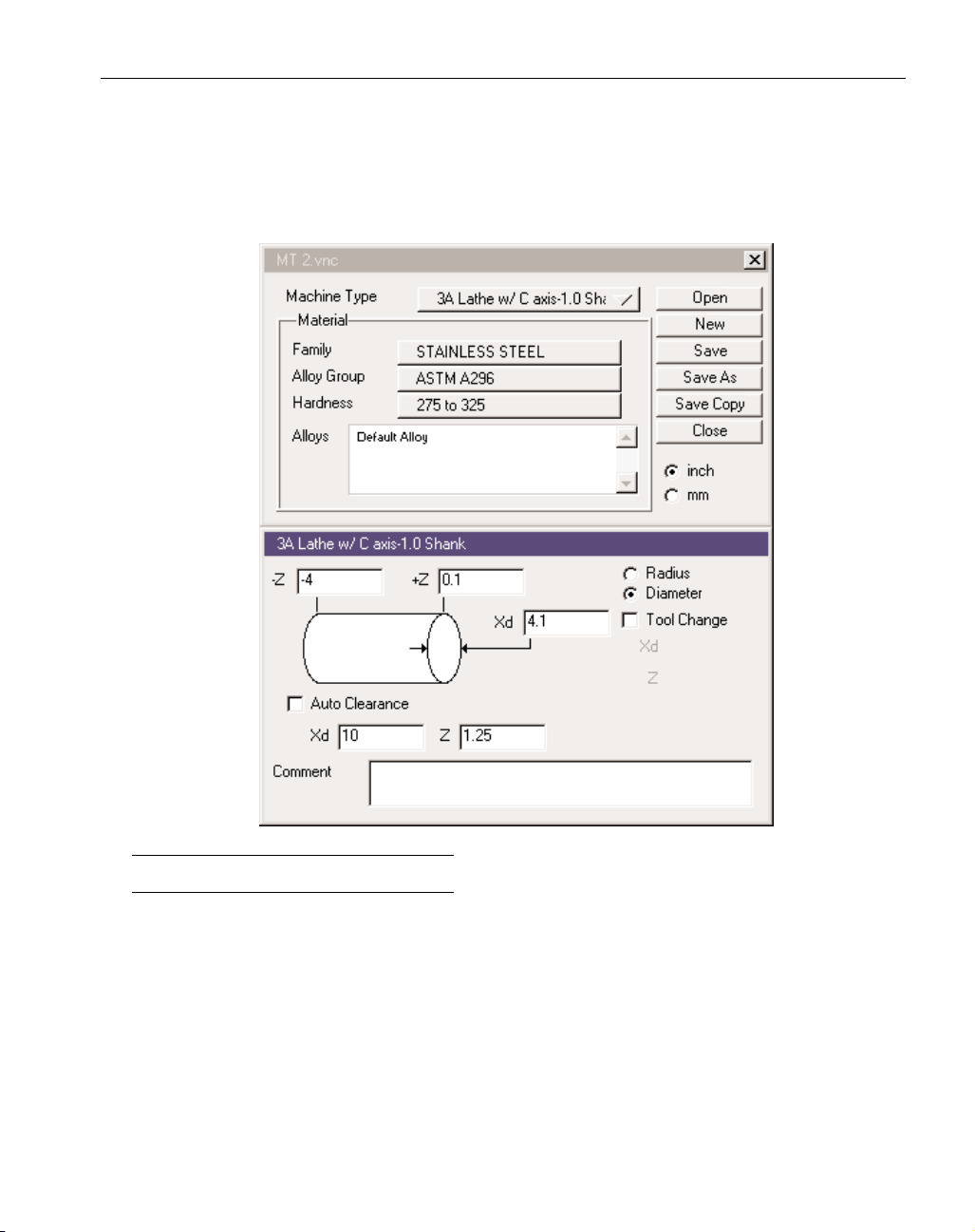
Selecting a Mill/Turn MDD signals the system that the part will contain both milling and turning
operations. When the Mill/Turn MDD is selected, the system automatically creates four coordinate
systems: the XZ plane which is used for turning operations, the YZ plane, which is used for OD
milling operations, the XY plane which is used for face milling operations, and the HY backside
plane which represents the back face of the part. Coordinate systems can be viewed and changed
using the CS list dialog which is accessed from the Top Level palette.
The Document Control Dialog for lathe and mill/turn parts contains options for programming the
part using radius values or diameter values. Either is a valid selection for Mill/Turn parts. However
the diameter selection will only apply to geometry and machining processes used for turning operations as noted. The ZX plane is used for all turning operations. When working in this CS, if the part
is being programmed in diameter, the user can enter diameter values. In all of the other coordinate
systems, which are used to create milling operations, all values will be treated as radius values
regardless of the selection made in the Document Control dialog. All text edit boxes, which require
4
◆
Mill/Turn Manual GFK-1711
Page 9
input from the user, are labeled indicating the type of value that should be entered. The labels on all
text edit boxes will read Xr (for radius) and Xd (for diameter) indicating the type of value to be
entered. The user should make sure the label is appropriate for the value being entered.
All other information entered in the Document Control Dialog is used as it is when programming
lathe parts. For more information about the information contained in this dialog, refer to the Lathe
Module manual.
COORDINATE SYSTEMS
NOTE: The terms coordinate system, plane and CS are used interchangeably throughout this manual.
When a 3 axis lathe with C axis MDD is selected, four coordinate systems are automatically created. CS’s are used to create geometry and machining operations on different areas of the part. The
first is the ZX plane which is used for turning operations. The second is the XY plane which is used
for face machining. The third CS is the HY backside plane which is used for machining the back
face with milling operations. The final CS is the YZ plane which is used for OD milling operations.
These four coordinate systems can not be modified.
5
GFK-1711 Mill/Turn
◆
Page 10
It should be noted that the system has an additional option referred to as the Advanced
Milling option which allows users to create and modify coordinate systems into any planar orientation and program positioning moves for milling operations. For the mill/turn
capabilities the Advanced Milling option provides the ability to create additional coordinate systems in any orientation and create milling operations which will use the non-standard coordinate systems for the machining CS. The four base CS’s created by the system
are not modifiable by Advanced Mill.
OVERVIEW
▲ A Coordinate System is a plane in space with an origin and three axes.
The origin is the point at which the axes intersect and serves as a zero reference point. The three
axes are the horizontal, vertical and depth axes. In the standard XY Plane, the X axis is the horizontal axis, the Y axis is the vertical axis and the Z axis is the depth axis. The current coordinate system
is the active coordinate system that is selected in the CS List Dialog. It refers to the CS that is currently being worked in.
▲ A Coordinate System is NOT a Workgroup.
Coordinate systems are completely independent of workgroups. Multiple coordinate systems can be
used in one workgroup and the same coordinate system can be used in multiple workgroups. Often
times it is helpful to have one coordinate system per workgroup, however that is only a convenience, not a rule.
▲ A coordinate system is an attribute of geometry elements (points, lines, circles, etc.).
Geometry is not contained in a coordinate system the way it can be said that geometry is contained
in a workgroup. When geometry is created, dimensional information must be entered to indicate
where the geometry should be located. When locational data is entered, there must be a referencing
system that makes the dimensional data meaningful. This is the role a coordinate system plays in the
creation of geometry. When using the Mill/Turn functionality, turning geometry is created in the ZX
plane and milling geometry is created in the XY plane for face work and the YZ plane for OD work.
CS LIST
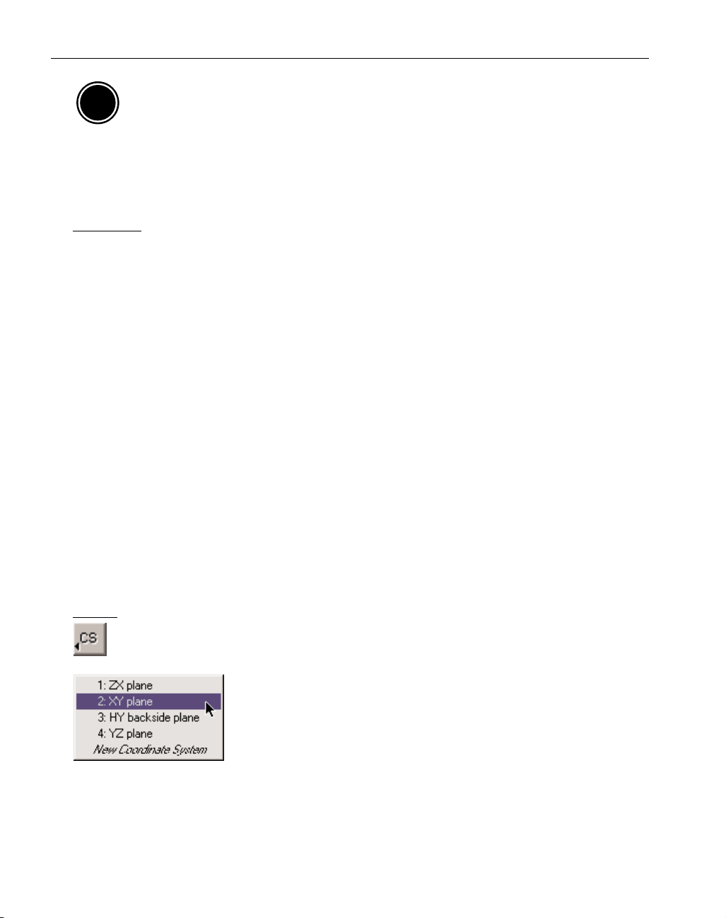
Coordinate System button: This button gives the user access to the CS List Pop-Up menu and
the CS List dialog. It is found among the 14 buttons in the Top Level palette.
CS List Pop-Up menu: Holding down the mouse button while selecting
CS Button will bring up a pop-up menu showing all of the coordinate
systems contained in the part file. The user can change the current
coordinate system by selecting one from the list and letting go of the
mouse button. After a coordinate system has been selected, the list will
disappear.
6
◆
Mill/Turn Manual GFK-1711
AM
Page 11
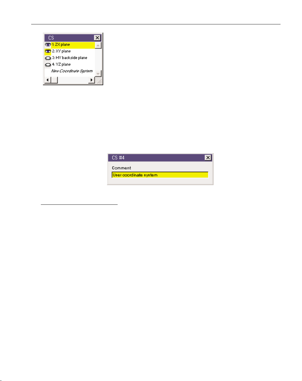
CS List dialog: Clicking on the CS Button will bring up the CS List
Dialog on the screen. This dialog displays a list of all existing coordinate systems, highlighting the current coordinate system. It is strongly
recommended that the CS List Dialog remain on the screen at all
times when working with multiple coordinate systems.
The CS List Dialog contains eyeball icons next to each of the coordi-
nate systems. Double-clicking a closed eyeball opens it, and viceversa. When open, the CS Frame Indicator for that coordinate system will be displayed on the
screen. This action does not affect the current CS, which will remain highlighted in the CS List
Dialog. The CS grid and axis markers will be based on the current CS.
Double-clicking on the name of a coordinate system in the CS List will open the CS Info Dialog for
that coordinate system. This dialog allows the user to enter a comment for each coordinate system.
The text entered in the Comment text box will appear in the CS List Dialog and as the title for the
CS Palette. Because the system names all new coordinate systems, User coordinate system, it is
strongly recommended to give each CS a unique name.
CS GRID AND AXIS MARKERS
The coordinate system (CS) grid and axis markers are very important tools when working with multiple coordinate systems. The CS grid graphically displays the planar orientation of the current coordinate system. The CS grid and axis markers will be drawn on the screen when the Show CS Button
in the taskbar is turned on (button depressed). When creating multiple coordinate systems, the CS
grid should be displayed on the screen at all times.
The axis markers will be placed at the origin of the current coordinate system. The axis marker
arrows show the positive direction of the horizontal (H) and vertical (V) axes. When the horizontal
and vertical axes align with one of the primary axes, the system labels the axis markers with X, Y
and Z. This is the case with three of the four coordinate systems used with Mill/Turn parts, the ZX
plane, the XY plane and the YZ plane. The other CS is labeled with HY because the X axis is
flipped in the opposite direction. At the intersection of the axis marker arrows, there is either a plus
“+” or minus “-”sign. This indicates the polarity (positive/negative direction) of the depth (D) axis
with respect to the current view.
7
GFK-1711 Mill/Turn
◆
Page 12
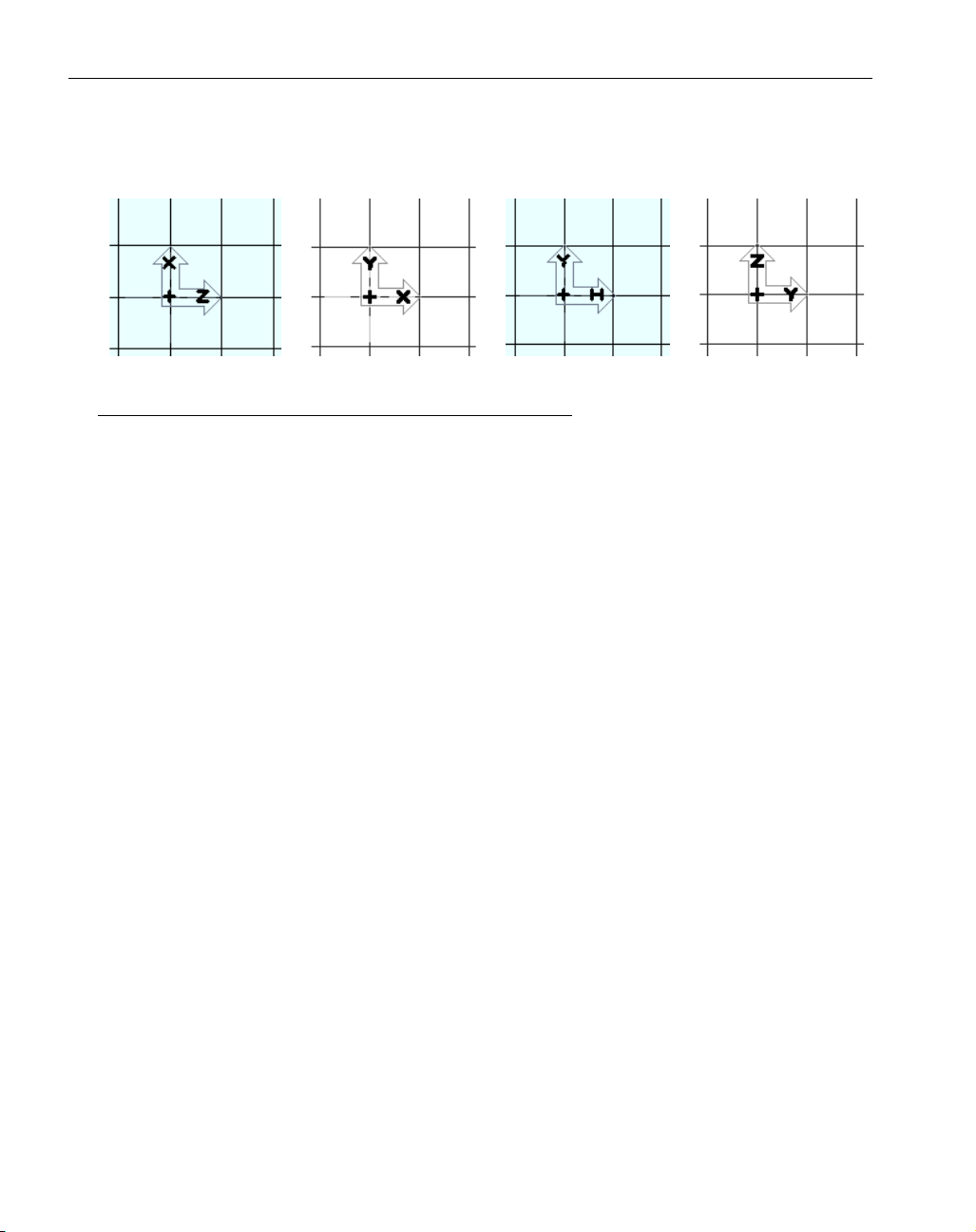
The grid is drawn in dark gray and shows the plane of the current coordinate system. Additional
light gray lines will be drawn showing where the coordinate system intersects with the stock size.
ZX Plane CS XY Plane CS HY Backside CS YZ Plane CS
USE OF COORDINATE SYSTEMS WITH MILL/TURN PARTS
For turning operations the designation of the machining coordinate system is set by the selection
made in the Lathe process dialog for OD, ID or front face. The selection made for the approach type
signifies the area of the part being machined and designates the appropriate machining coordinate
system. However, with milling operations, the proper CS must be set by the user, usually through
the tool orientation.
The machining CS is used to determine how the tool will approach the part. For turning operations,
the Approach Type selection designates the axis along which the tool will approach and cut the part,
while for milling operations the tool orientation typically designates the axis of tool approach.
Turning operations also require the tool orientation to be specified, however, this information is not
used to determine the machining CS, however it is very important to designate the appropriate orientation in order to achieve the correct toolpath.
The various coordinate systems are primarily used for creating milling operations. As the following
figures illustrate, the system does support Y axis moves for milling operations. Some mill/turn
machines do not support the Y axis, and instead use the C axis to facilitate these type of moves. C
axis continuous moves will be discussed in the Rotary Milling section. Users should know whether
their mill/turn machines support the Y axis and program their parts accordingly. This issue is discussed further in the Machining and Rotary Milling sections of this manual.
8
◆
Mill/Turn Manual GFK-1711
Page 13
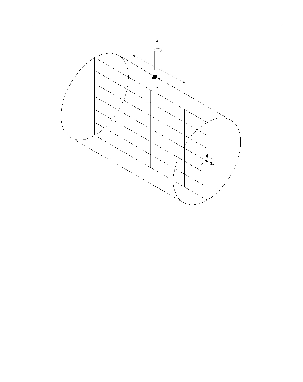
Figure 4: XZ Plane: Turning
9
GFK-1711 Mill/Turn
◆
X axis
Lathe Tool
Z axis
Page 14
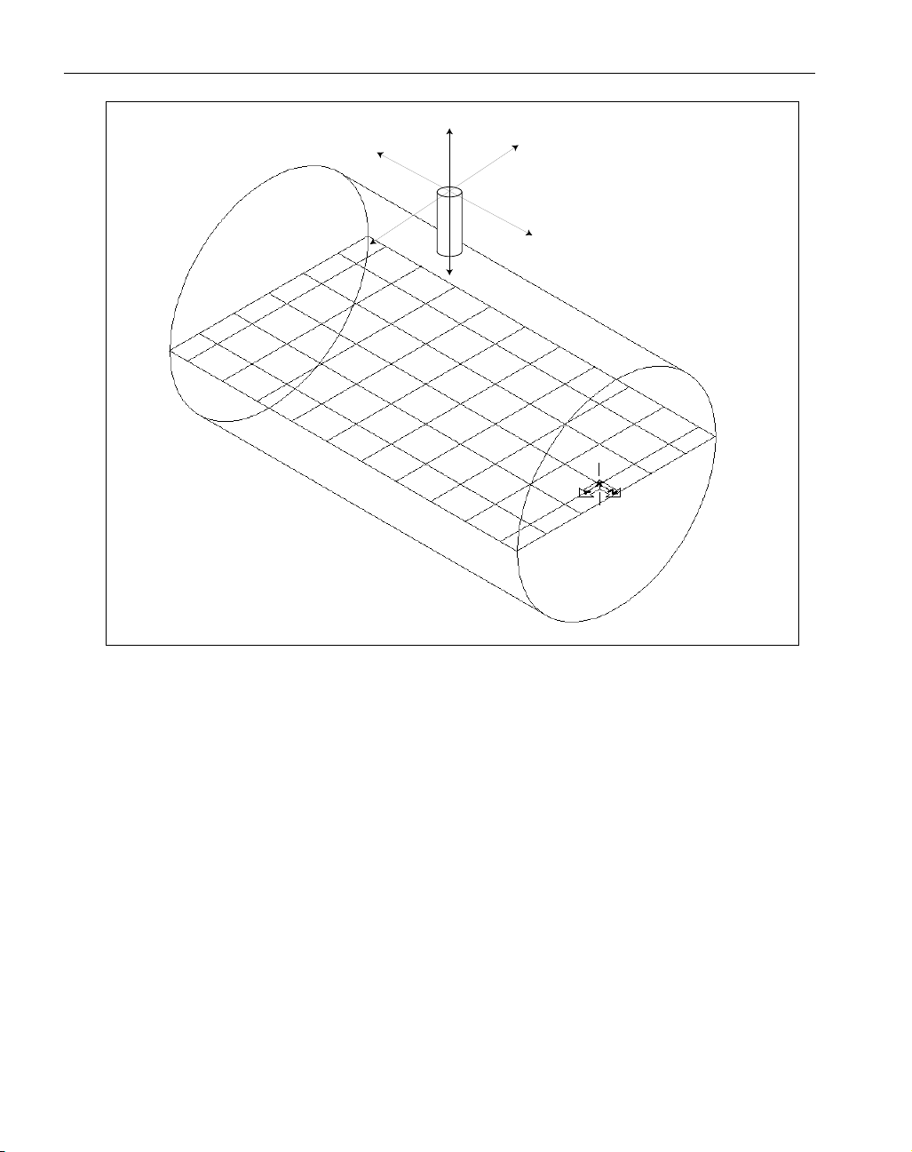
Figure 5: YZ Plane: OD Milling with Y axis moves
10
◆
Mill/Turn Manual GFK-1711
X axis
Mill Tool
Y axis
Z axis
Page 15
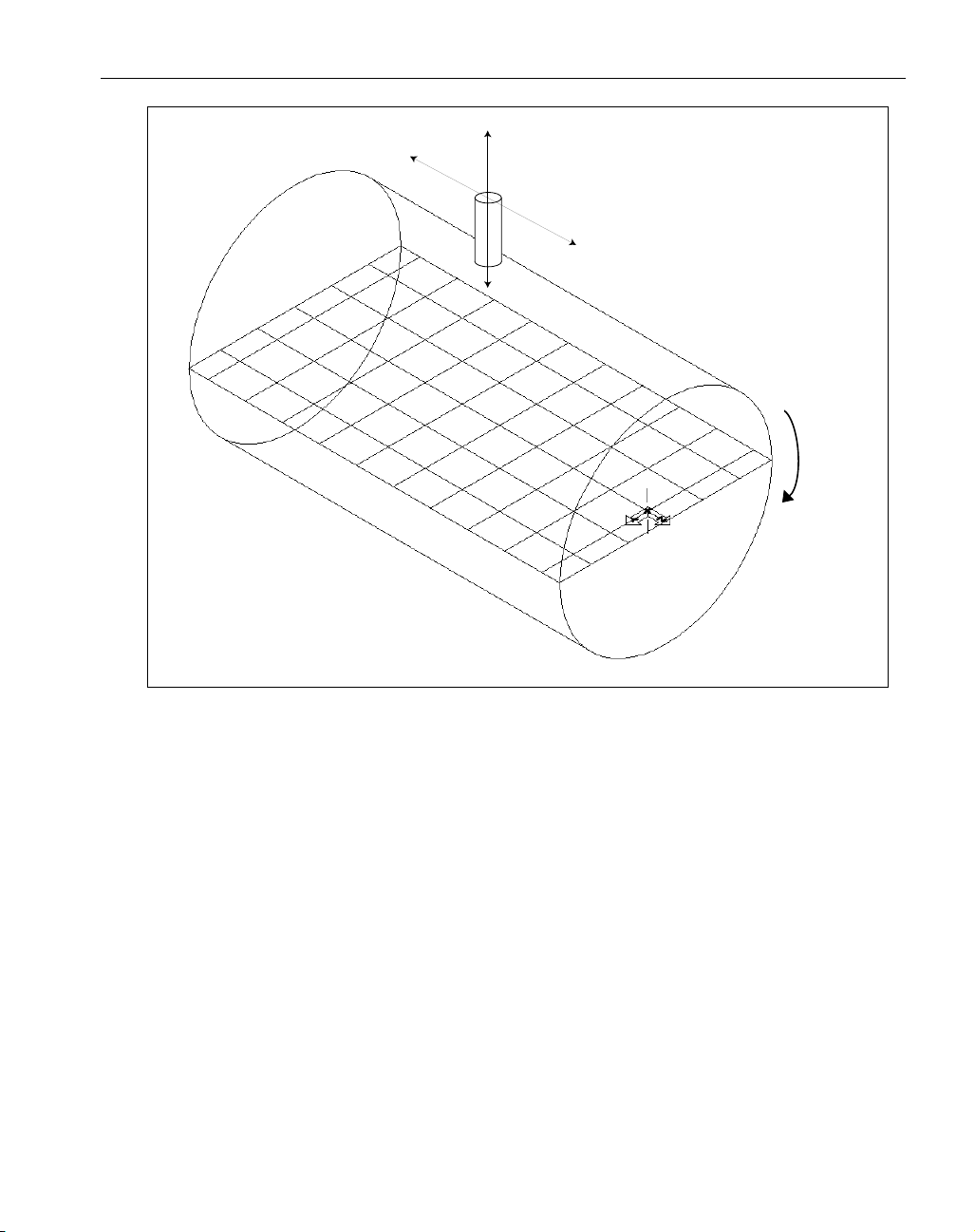
Figure 6: YZ plane, OD Milling with C axis moves
11
GFK-1711 Mill/Turn
◆
X axis
Z axis
Mill Tool
C axis
Page 16
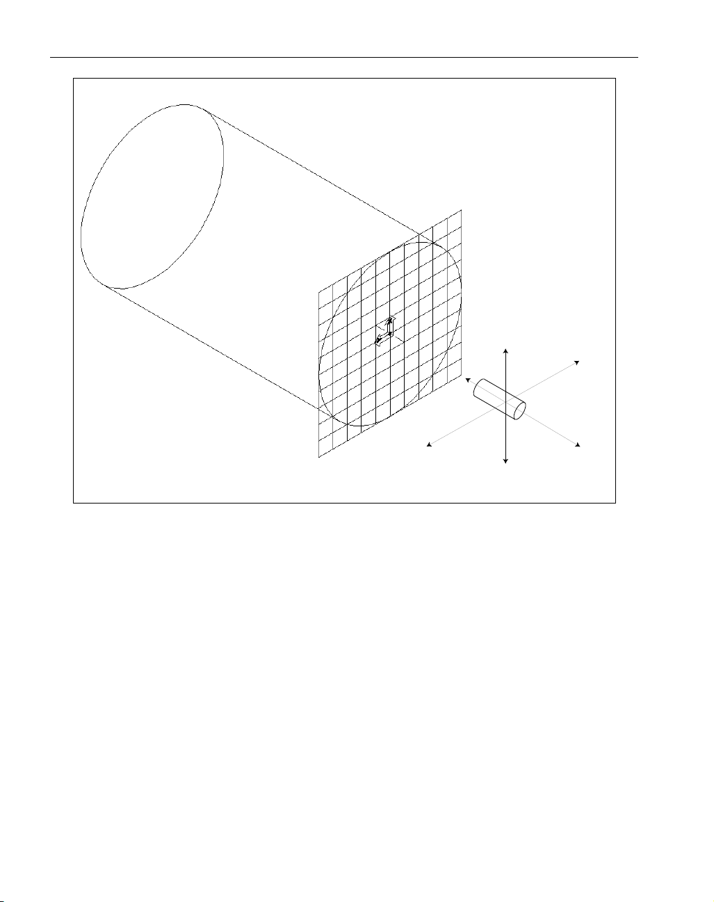
Figure 7: XY Plane, Front Face Milling with Y axis moves
12
◆
Mill/Turn Manual GFK-1711
X axis
Y axis
Mill Tool
Z axis
Page 17
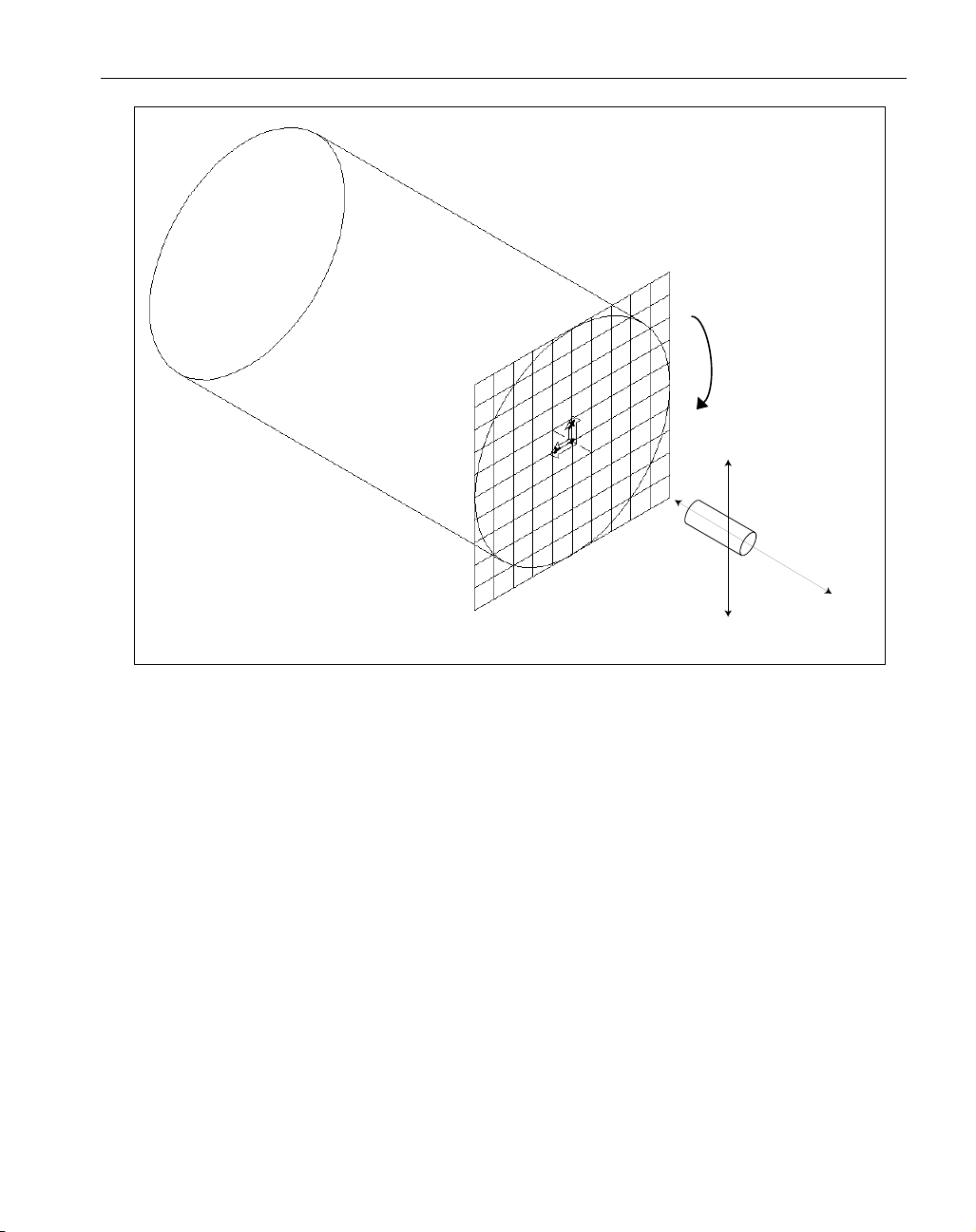
Figure 8: XY Plane, Front Face milling with C axis moves
13
GFK-1711 Mill/Turn
◆
C axis
X axis
Mill Tool
Z axis
Page 18
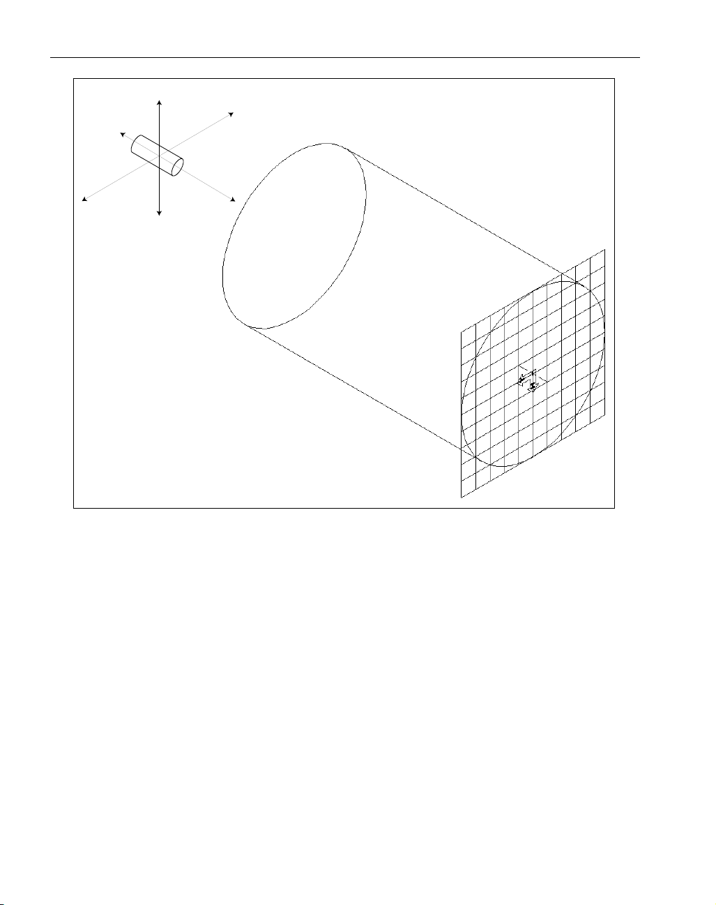
Figure 9: HY Plane: Back Face Milling with Y axis moves
14
◆
Mill/Turn Manual GFK-1711
X axis
Y axis
Mill Tool
Z axis
Page 19
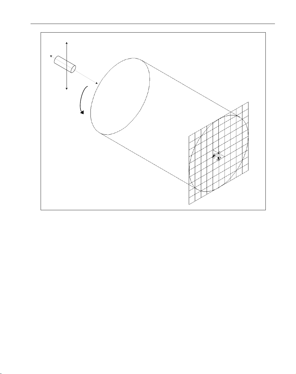
Figure 10: HY Plane: Back Face Milling with C axis moves
At first glance CS2: XY Plane and CS3: HY Backside plane may appear identical when seen from
an isometric view. The user may wonder why there are two CS’s in the same location. A close
examination of the two CS’s shows the difference between them. The difference between the XY
plane and the HY backside plane is the axis markers.
The XY plane, which represents the front face has a "+" sign at the intersection of the markers indicating that the positive direction of the depth axis is projecting outward. The Back face plane
(labeled as HY) has a “–” sign on the axis markers, indicating that the view is from the negative
depth axis. The positive depth axis projects out from the backside of the part. Essentially the difference between the XY plane and the HY backside plane involves the depth axis along which the tool
will approach the part.
When machining either the front face or the back face, the tool must approach the part along the Z
axis. The question is whether it will approach along the positive Z axis (front face) or the negative Z
axis (back face). The way the system is set up, a tool must approach the part along the positive Z
axis.
Therefore in order for the tool to approach the part to machine the back face, the machining coordi-
15
GFK-1711 Mill/Turn
◆
X axis
Mill Tool
Z axis
C axis
Page 20

nate system must be flipped so that the positive direction of the Z axis is projecting outward from
the backside of the part. This is the reason that two coordinate systems are created to facilitate face
machining.
GEOMETRY CREATION
Geometry can be created in any coordinate system. The CS the geometry is assigned to does not
have any bearing on the machining CS. Typically, the machining CS is designated by the tool orientation. If geometry is not created in the appropriate CS for the type of operation that is being created, it is very likely that the resulting toolpath will not produce the desired results. The toolpath will
be created based on the machining CS, regardless of the CS of the geometry. Geometry will be
machined as it is viewed from the machining CS.
Geometry should be created in the appropriate coordinate system for the type of machining operation to be created. Geometry that defines the cut shape for OD machining operations should be created in the YZ plane. Likewise, geometry for front face operations should be created in the XY
plane and geometry for back face operations should be created in the HY backside plane. It may be
helpful when creating geometry to be machined on the back face to force the depth of the geometry
so that when viewed on the screen, it appears in the correct location. This is recommended for visualization purposes only, as the machining operation and depths of cut will be calculated from the
information entered in the machining process dialogs not the location of the selected geometry.
All geometry for OD milling operations must be created in the YZ plane. Geometry is created in a
position as if it were to be machined in the C0 position. The rotation is accomplished when the toolpath is created by entering an angle value in the machining process dialog. The position C0 is along
the positive direction of the X axis in the standard YZ plane. The system allows the user to designate a start angle when positioning the C axis. All geometry for OD operations must be created in
the standard YZ plane, regardless of the start angle. As a result, often times geometry will not be
created in the exact planar location in which it will be machined. For example, if a flat slot is created on the OD to be machined at a start angle C90, the geometry would be created at C0 and when
the toolpath is created it will be rotated into position.
Geometry can also be created and viewed radially or wrapped when the Rotary Milling option is
installed. Refer to the Rotary Milling section at the end of this manual for more information.
TOOL ORIENTATION
The Mill tool creation dialog contains an orientation diagram when creating a Mill/Turn part.
Setting the proper tool orientation is very important because the tool orientation determines the
machining coordinate system for the process. The system uses the designated machining CS in order
to properly rotate the part. The system rotates the part so that the tool will approach normal to the
cutting plane of the machining coordinate system. In other words the tool will approach and cut
along the positive depth axis of the machining coordinate system.
16
◆
Mill/Turn Manual GFK-1711
Page 21
If the Advanced Milling option is installed users are able to explicitly set the appropriate
machining coordinate system. However, if the advanced Milling option is not installed,
the machining CS will be set by the orientation of the tool.
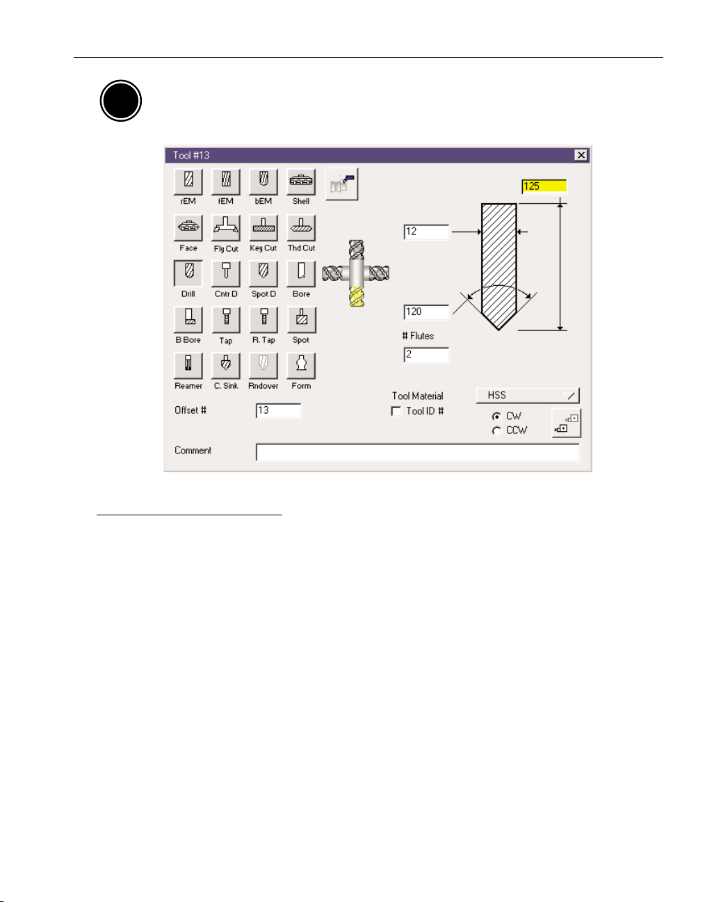
TOOL ORIENTATION DIAGRAM
Setting the proper tool orientation is very important as it determines the axis along which the tool
will approach and machine the part. There are two basic axes along which the tool will travel, the X
axis, for OD operations, and the Z axis for face operations. To select the tool orientation, click on
one of the four positions on the diagram so that it becomes highlighted.
If the tool orientation is not set correctly, the toolpath that will be generated will not produce the
desired results. Often times, the system will not be able to create a toolpath if the tool orientation is
not set correctly. Always check the tool orientation diagram if the toolpath (or lack thereof) does not
seem correct.
Figure 11 labels the tool orientation diagram according to the approach axis of the selection and also
what section of the part should be cut given the selection. It should be noted that a tool approaching
along the X axis, while typically used for OD work can also be applied to milling operations cutting
the face.
17
GFK-1711 Mill/Turn
◆
AM
Page 22
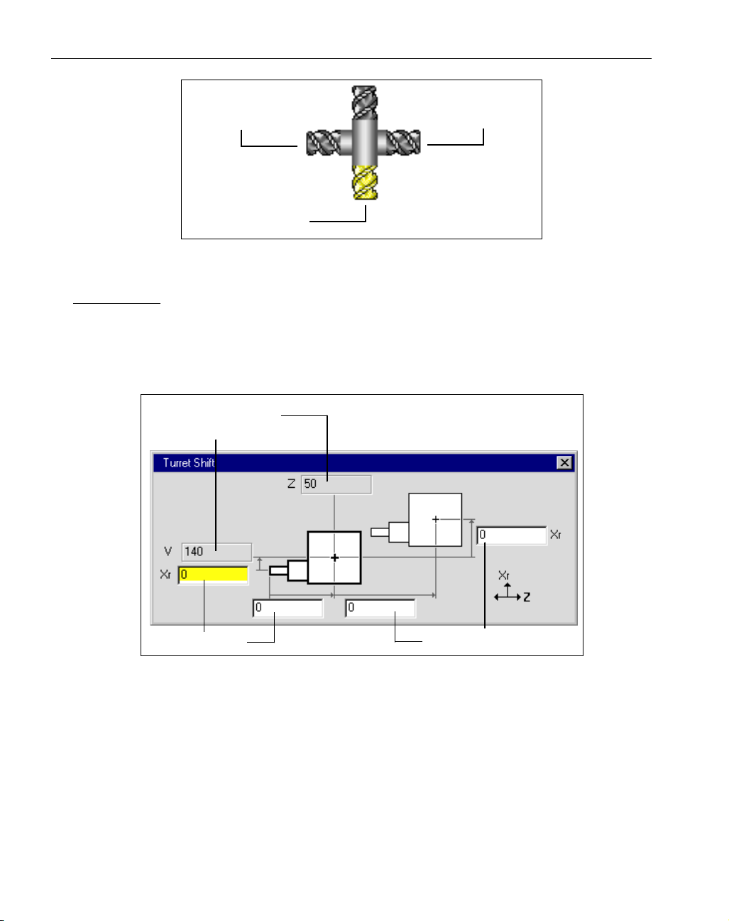
Figure 11: Tool Orientation Diagram
TURRET SHIFT
The tool creation dialog for milling tools contains a turret shift button when programming a
Mill/Turn part. The turret shift for milling tools functions as it does for turning tools. Turret shift
allows users to specify a distance from the preset point, the theoretical tip of the tool, to the center
of the turret. This dialog can also be used to specify a different tool change position for individual
tools.
Figure 12: Mill Turret Shift
18
◆
Mill/Turn Manual GFK-1711
Z Axis Approach
(Front Face)
X Axis Approach
(OD)
Z Axis Approach
(Back Face)
Default Tool
Change Position
Preset Point
Turret Shift
Page 23
Machining Operations
MACHINING
When one of the Mill/Turn MDD's is selected, the machining palette can be used to create milling
operations and turning operations. The available machining processes are the same as those contained in the standard Mill and Lathe modules. Either type of process can now be applied to a single
part, a mill/turn part. Turning functions include contouring, roughing, threading and center line
drilling. Milling functions include live tool drilling, contouring, roughing, surfacing and threadmilling. (The Surfacing process requires the SolidSurfacer option.) All of these processes operate in
the same manner as they do when working on either mill only or lathe only parts. For more information on the specific processes, please refer to the appropriate machining module manual.
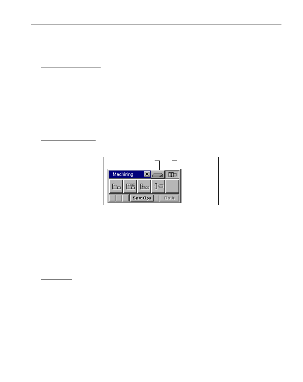
MACHINING PALETTE
When a Mill/Turn MDD is selected, the Machining Palette contains two buttons in the title bar
which allow users to toggle between mill and lathe processes.
Figure 13: Mill/Turn Machining Palette
When toggling between the milling and turning processes, the Process List will be cleared of any
existing Process Tiles. A Process Group (multiple process tiles in one process list) can not contain a
combination of milling and turning processes. Milling and turning processes must be created in different process groups. Turning machining processes function as they do with the standard Lathe
module. Milling functionality has been enhanced to provide specifically for milling operations on
turning parts.
ROTATE TAB
Milling Process dialogs (Drilling, Contouring, Roughing, Surfacing and Threadmilling) contain a
Rotate tab when a Mill/Turn MDD is selected. The Rotate tab allows the user to designate C axis
rotation for the operation.
The Rotate tab in milling processes contains two selections for rotating the part, Position and Rotary
Milling. The Rotary Milling selection will only be available if the Rotary Milling option is installed.
Rotary Milling is discussed in the following section.
19
GFK-1711 Mill/Turn
◆
Mill Toggle Lathe Toggle
Page 24
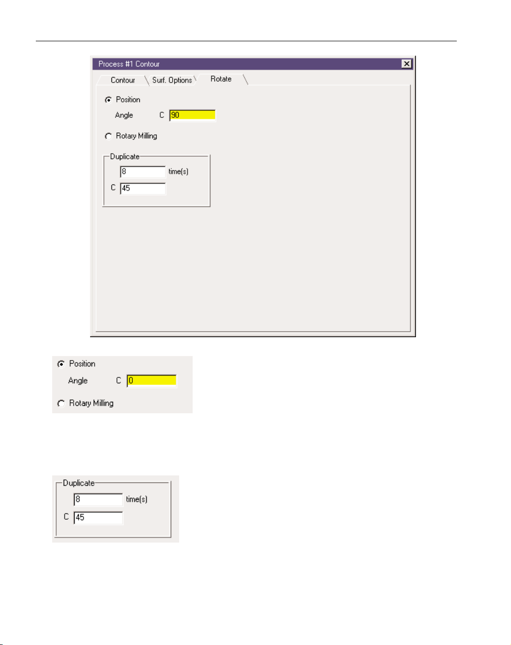
The Position selection allows the user to enter an angle of rotation for the C axis, which designates the position in which the
toolpath will be created. When the toolpath is generated, the system will display it in the proper location based on the angle
value entered. It is independent of the geometry selected.
Geometry created for face operations should be based on the XY plane and geometry for OD operations should be created in the YZ plane. All geometry for OD operations is created in the YZ plane
in the C0 position. The position rotation is accomplished when the toolpath is created. The posted
code will contain the appropriate C axis positioning moves.
The Duplicate function allows for subroutine repeats at equal angular intervals of the toolpath generated by the operation. The system
will create the toolpath dictated by the Position information and
duplicate that toolpath a specified number of times at the interval
angle position entered in the C text box. The value entered in the
times text box is the additional number of times the toolpath will be
repeated. For example, if you are creating a toolpath using Position at a specified C angle, the
process will create the toolpath at that angle and then duplicate it the given number of times at the
given angle intervals. Thus the Duplicate # is the total number of subroutines the operation is to be
performed minus one for the original step.
20
◆
Mill/Turn Manual GFK-1711
Page 25

Figure 14: C Axis Angular Positions
Figure 14 is viewed from the front face of the part (XY plane) and illustrates the angular positions
associated with positioning the C axis. The C0 position corresponds to the positive direction of the
X axis. Angular rotation proceeds in a clockwise direction. Negative values are valid for start angle
positions. For example, a value of -45 could be used which is identical to entering 315. The value
entered for the start position should be in angle measured in degrees.
Y-AXIS INTERPOLATION & C-AXIS INTERPOLATION
To perform Y-axis moves the user must have a mill/turn machine which supports Y axis. However,
often times machines that do not support the Y axis can create Y-axis moves by continuous rotary
movement of the C axis, C-axis interpolation. The rotation of the C-axis will be used to achieve any
movements needed in Y. To achieve this, be sure to select Rotary Milling in the Process dialog.
A Y-axis toolpath cannot be wrapped. The system only produces Y axis moves when the Position
option is used in the Process dialog. In other words, Y axis moves will not be generated when creating a wrapped or rotary milling toolpath. When Rotary Milling is being used, all movements are
converted to C-Axis Interpolation.
The following images illustrate some of the differences in Y-axis and C-axis moves. Figure 15
shows the same process being machined. The first set of images comes from a machine that does
not have Y-axis capabilities, the second set from a machine that does support Y-axis. (NOTE: a Yaxis capable machine can produce this same movement by selecting Rotary Milling in the machining dialog.)
Figure 16 illustrates a contour being cut on a part’s face. The first set of images illustrates how a
machine without Y-axis would handle the contour while the second image shows a machine with Yaxis. The last image in both sets shows the tool as an overlay to demonstrate all movement.
21
GFK-1711 Mill/Turn
◆
C0
C45
C270 (-90)
C180
C90
Page 26

Figure 15: OD milling, C-Axis vs. Y-axis interpolation
Figure 16: Face milling, C-Axis vs. Y-axis interpolation
22
◆
Mill/Turn Manual GFK-1711
C-Axis Interpolation
Y-Axis Interpolation
C-Axis Interpolation
Y-Axis Interpolation
Page 27

Rotary Milling & Wrapping
The Rotary Milling option is an add-on option which enhances the Mill/Turn functionality. The
Rotary milling option allows for continuous C axis rotation when programming milling operations.
This is often referred to as wrapping. This section describes functions that are specific to the system
when the Rotary Milling option is installed. This section assumes a familiarity with the standard
Mill/Turn functionality described previously in this manual.
ROTARY MILLING VIA C AXIS INTERPOLATION
The term rotary is used to signify the continuous or simultaneous movement of a rotary axis. In the
case of mill/turn parts, the rotary axis is referred to as the C axis. The Rotary Milling option allows
for the wrapping of toolpaths about the C axis by rotary interpolation of the C axis during a milling
operation. When the Rotary Milling option is installed, the Rotate tab for milling processes contains
two rotation options: Position and Rotary Milling. The operation can either be programmed as a
simple position move (Position) or as a wrapped toolpath which will have continuous C axis motion
(Rotary Milling). The Position option is described in the preceding Machining section. The Rotary
Milling option is described in this section.
FLAT VS RADIAL GEOMETRY
Geometry can either be created as flat geometry or radial geometry. Flat geometry is defined using
XYZ values, while radial geometry is defined using XZC values, where X designates the radius or
diameter and C designates an angle of rotation for the C axis. Geometry does not need to be
wrapped in order to be machined using the Rotary milling function. The toolpath that results with
the Rotary Milling option checked will be the same whether the geometry selected for the cut shape
is flat or wrapped.
Two interface items must be used in order to create and view radial geometry. First, the Rotary
Milling option must be checked in the Workgroup Info dialog. The Workgroup info dialog is
accessed from the Workgroup List context menu, which comes up by right mouse clicking on the
23
GFK-1711 Mill/Turn
◆
Page 28

title bar of the Workgroup List dialog.
Figure 17: WG List context menu and WG Info Dialog
In addition to the Rotary Milling checkbox, the Wrap Geometry button in the Taskbar must
be depressed in order to view geometry radially on the screen. When both of these items are
appropriately checked and depressed, the system will be in radial mode. When working in
radial mode, geometry dialogs which require coordinate input will contain specifications for a C
value, which is the angle of rotation and a radius value. For example, with point creation using coordinates, the dialog will not be labeled with X, Y and Z, but rather Z, C and R.
Figure 18: Geometry Dialog in Radial mode
Modify Menu items
When working in radial mode certain Modify functions are enhanced to provide for radial value
input. The two primary functions are the Force Depth item and the Translate item. The Force Depth
item is a Force Radius item when in radial mode. Users can enter an absolute radius value and the
selected geometry will be changed to that radius.
24
◆
Mill/Turn Manual GFK-1711
Page 29

Figure 19: Geometry and toolpath variations with Wrap Geometry button active.
25
GFK-1711 Mill/Turn
◆
Designated as
Designated as
Position
Rotary Milling
in the machining dialog Designated as
in the machining dialog Designated as
Rotary Milling
Position
in the machining dialog
in the machining dialog
Page 30

◆
Mill/Turn Manual GFK-1711
26
EXERCISE 1 : CLUTCH BASKET
This exercise provides instruction on creating milling operations on
mill/turn parts. There is minimal turning work included in the exercise, rather we will begin from a casting and primarily create milling
operations to be applied to the casting.
The installation CD contains sample parts which can be installed on
your system. In order to do this exercise, you will need to install the
Clutch Basket.vnc file.
Following are instructions for installing the part file.
• Right mouse click on the CD icon and select the Open item.
• Open the Samples folder.
• Open the Disk 1 folder and double click on the Setup.exe icon.
This will initiate the setup for the installation of the sample parts.
• Follow the prompts to complete the installation process.
If you did not change any of the destination directory information in
the installation, the Sample Parts folder will be located in the Gibbs
folder. There will be a Mill/Turn folder in the Sample Parts folder
which contains the necessary part to complete this exercise.
In order to use the Mill/turn capabilities of the system, you must be
working in the Level 2 interface. The Level 2 interface has a 14 button Top Level palette. You will need to make sure that you are working in the Level 2 interface for this exercise.
• Select the Interface item from the Preferences sub-menu which is under the
File menu.
• Make sure that the Level 2 radio button is selected under the New Part
section.
• Open the Clutch Basket.vnc file.
In the Document Control Dialog, the Machine Type selected is a 3A
Lathe w/ C axis-1.0 shank. There are four different Machine
Definition Documents (MDD) contained in the Machine Type pop-up
Page 31

GFK-1711 Mill/Turn Exercise
◆
27
menu that are used to create MIll/Turn part files. They are all labeled
3A Lathe w/C axis, but have different shank sizes. In this case we
have selected a 1.0 shank.
When one of the 3 axis lathe MDD's is selected, four coordinate systems are automatically created by the system: ZX plane, XY plane,
HY backside plane and YZ plane. These coordinate systems are used
to properly position geometry in order to cut the various areas of the
part. There is a coordinate system section at the beginning of this
document which describes their use.
• Click on the CS button in the Top Level Palette.
The CS List dialog will come up on the screen and contain these four
coordinate systems.
In order to simplify this exercise, the file contains geometry and
tools that have already been created.
The tools for this part have already been created. There should be a
total of five tools in the tool list including a 2” drill, .25” Rough
Endmill, .52” Form Tool, .625” Spot Drill and .375” Drill
• Click on the WG button in the Top Level palette.
The Workgroup List dialog should have three workgroups which
contain the geometry for different elements of the part.
Page 32

◆
Mill/Turn Manual GFK-1711
28
Following are images of the geometry that is contained in each
workgroup. You should look through all of the workgroups to ensure
that the geometry in your file matches the geometry shown here.
The first workgroup, named Casting, is designated as Part Stock in
the WG info dialog. The casting geometry is defined in the ZX plane
which is the standard plane for turning operations. Nothing will be
done with this geometry, it simply provides the initial part stock to
which we will apply several milling operations. When the part is rendered the initial stock condition will be based on this geometry.
WG 1: Casting
Page 33

GFK-1711 Mill/Turn Exercise
◆
29
Workgroup 2 contains geometry defined in the YZ plane. This geometry will be used to create angled slots on the OD of the part.
WG2: Teeth geometry
Workgroup 3 contains geometry defined in the YZ plane which will
be used to cut slots on the OD of the part. This workgroup also contains a point which will be used to create bolt holes on the front of
the part.
Page 34

◆
Mill/Turn Manual GFK-1711
30
WG3: Drill point and Contour geometry
• Open the Tool list by depressing the Tool List button in the Top Level
palette.
• Open Tool #1 dialog.
The first machining operation will be to drill out the center of the
part so the tool orientation for the first four tools is set to approach
along the Z axis.The tool orientation diagram should look like the
following image.
This orientation designates a Z axis approach which is the necessary
orientation for front face operations.
The first operation will be the only Lathe operation in this exercise.
In order to create lathe operations the Machining palette needs to be
toggled to the Lathe processes.
Selected Tool Orientation
Page 35

GFK-1711 Mill/Turn Exercise
◆
31
• Click on the Lathe toggle button in the title bar of the Machining palette so
that the Lathe process tiles are displayed.
• Create a Hole process using Tool #1 and enter the following information in
the Hole Process dialog.
• Click on Do It in the Machining palette.
The next operation to be created will be a contour. All of the remaining machining operations created in this exercise are milling operations. In order to create milling operations the Machining palette
needs to be toggled to the Mill processes.
• Click on the Mill toggle button in the title bar of the Machining palette so
that the Mill process tiles are displayed.
• Open Tool #2 dialog.
The tool orientation diagram should look like the following image.
This orientation designates an X axis approach which is the necessary orientation for OD operations.
• Be sure you are in WG3: Drill & Contour
• Switch to CS4: YZ plane for better visualization of the operation.
Selected Tool Orientation
Page 36

◆
Mill/Turn Manual GFK-1711
32
• Create a contour operation using tool #2, the .25” Endmill. Enter values in
the contour process dialog as seen in the following image.
• Click on the Rotate tab and enter the following values. For the proper tool-
path be sure to specify that we are working in the YZ plane.
This will create an operation that starts at C0 then gets rotated clockwise by 30˚ and machined 11 more times.
Page 37

GFK-1711 Mill/Turn Exercise
◆
33
• Select the geometry at the location shown in the following image.
• Orient the machining markers so the cut is on the inside of the geometry
as indicated in the following image.
Page 38

◆
Mill/Turn Manual GFK-1711
34
• Click on Do It. The results of the operation should look like the following
image.
• Open the Rendering palette and press Play.
Page 39

GFK-1711 Mill/Turn Exercise
◆
35
The third and fourth operation will create bolt holes.
• Switch to CS2: XY plane for better visualization of the operation.
• Create a Hole operation using tool #4, the .625” Spot Drill. Enter values in
the hole process dialog as seen in the following image.
• Click on the Rotate tab and enter the following values. For the proper tool-
path be sure to specify that we are working in the XY plane.
Page 40

◆
Mill/Turn Manual GFK-1711
36
• In the same process group create a second Hole operation using tool #5,
the .375” Drill. Enter values in the hole process dialog as seen in the following image. There is no need to check the Rotate tab as the values will not
change from the prior drill process.
• Select the point shown in the following image and click on Do It.
Page 41

GFK-1711 Mill/Turn Exercise
◆
37
The results of the operation should look like the following image.
• Switch to CS4: YZ plane
• Change to WG 2: Teeth.
Page 42

◆
Mill/Turn Manual GFK-1711
38
• Create a Contour operation using tool #3, the .52” Form tool. Enter the
following information in the Process dialog.
• Click on the Rotate tab and enter the following information. Be sure to
specify the YZ plane as the machining CS.
Page 43

GFK-1711 Mill/Turn Exercise
◆
39
This will create a contour operation that starts ar C90˚ and repeats 39
times in 9˚ intervals.
• Click on the line in this workgroup. Place the Machining Markers as indicated.
• Be sure to place the start and stop indicators clear of the casting geometry.
Double clicking on the eye icon for the Casting workgroup will display this
geometry in gray. This will help you to properly place the markers.
Page 44

◆
Mill/Turn Manual GFK-1711
40
• Click on Do It. The results of the operation will look like the following
image.
Page 45

GFK-1711 Mill/Turn Exercise
◆
41
• Open the Rendering palette and click Play.
EXERCISE 2 : COUPLING
This exercise provides instruction on creating milling operations on
mill/turn parts. There is no turning work included in the exercise,
rather we will begin from a casting and only create milling operations to be applied to the casting. For turning information, please
refer to the Lathe module manual.
This part file may be found on the system CD, please see exercise #1
for information on retrieving the part file.
You will need to make sure that you are working in the Level 2 interface for this exercise.
• Open the Coupling.vnc file.
In the Document Control Dialog, the Machine Type selected is a 3A
Lathe w/ C axis-1.0 shank. There are four different Machine
Definition Documents (MDD) contained in the Machine Type pop-up
Page 46

◆
Mill/Turn Manual GFK-1711
42
menu that are used to create MIll/Turn part files. They are all labeled
3A Lathe w/C axis, but have different shank sizes. In this case we
have selected a 1.0 shank.
When one of the 3 axis lathe MDD's is selected, four coordinate systems are automatically created by the system: ZX plane, XY plane,
HY backside plane and YZ plane. These coordinate systems are used
to properly position geometry in order to cut the various areas of the
part. There is a coordinate system section at the beginning of this
document which describes their use.
In order to simplify this exercise, the file contains geometry and
tools that have already been created.
• Click on the WG button in the Top Level palette.
The Workgroup List dialog should have four workgroups which contain the geometry for different elements of the part.
Following are images of the geometry that is contained in each
workgroup. You should look through all of the workgroups to ensure
that the geometry in your file matches the geometry shown here.
Page 47

GFK-1711 Mill/Turn Exercise
◆
43
The first workgroup, named Casting, is designated as Part Stock in
the WG info dialog. The casting geometry is defined in the ZX plane
which is the standard plane for turning operations. Nothing will be
done with this geometry, it simply provides the initial part stock to
which we will apply several milling operations. When the part is rendered the initial stock condition will be based on this geometry.
WG 1: Casting
Workgroup 2 contains geometry defined in the XY plane which will
be used to contour a flange on the front face of the part. This workgroup also contains points which will be used to create bolt holes on
the front and back flanges of the part.
Page 48

◆
Mill/Turn Manual GFK-1711
44
WG2: Front Flange
Workgroup 3 contains geometry defined in the YZ plane. This geometry will be used to create flat slots and holes on the OD of the part.
WG3: OD Flat Slots
Page 49

GFK-1711 Mill/Turn Exercise
◆
45
Workgroup 4 also contains geometry defined in the YZ plane, which
will be used to create a radial slot on the OD of the part.
WG4: OD Radial Slots
The first set of machining operations will create bolt holes on the
front face of the part.
• Change to WG2: Front Flange.
• Change to CS 2: XY Plane.
• Open the Tool list by depressing the Tool List button in the Top Level
palette.
The tools for this part have already been created. There should be a
total of eleven tools in the Tool list. The tool creation dialog for mill
tools contains a tool orientation diagram when creating a Mill/Turn
part.
The first set of operations will be machining the face of the part so
the tool orientation for the first four tools is set to approach along the
Z axis.
• Open Tool #1 dialog.
Page 50

◆
Mill/Turn Manual GFK-1711
46
The tool orientation diagram should look like the following image.
This orientation designates a Z axis approach which is the necessary
orientation for front face operations.
All of the machining operations created in this exercise are milling
operations. In order to create milling operations the Machining
palette needs to be toggled to the Mill processes.
• Click on the Mill toggle button in the title bar of the Machining palette so
that the Mill process tiles are displayed.
• Create a Hole process using Tool #1 and enter the following information in
the Drilling Process dialog.
Selected Tool Orientation
Page 51

GFK-1711 Mill/Turn Exercise
◆
47
• Click on the Rotate tab and enter the following information in the Rotate
window.
If you do not have the Advanced Milling option installed, the
Machining CS pop-up menu at the top of the Rotate window will not
be there. The Machining CS will be set by the tool in that case. The
Machining CS pop-up menu will default to the CS designated by the
tool, although the user does have the ability to designate a different
Machining CS using the pop-up menu. The Z axis approach, which is
set for this tool, designates the XY plane as the machining CS. The
XY plane is the coordinate system used for front face operations.
• Create another Hole process in the same Process list using Tool #2 and
enter the following information in the Hole Process dialog.
Page 52

◆
Mill/Turn Manual GFK-1711
48
The information in the Rotate window is the same as the previous
operation so you should not need to change any of the information.
• Select the point just inside the square flange in the XY plane.
• Click on the Do it Button in the Machining palette.
Page 53

GFK-1711 Mill/Turn Exercise
◆
49
The resulting toolpath should look like the following image.
Now, we will create a series of bolt holes that will be machined on
the back flange.
• Create a Hole process with Tool #1 and enter the following information in
the Hole Process dialog.
Page 54

◆
Mill/Turn Manual GFK-1711
50
• Click on the Rotate tab and enter the following information in the Rotate
window.
• In the same process group, create another Hole process using Tool #3 and
enter the following information in the Hole Process dialog.
The information in the Rotate window is the same as the previous
operation so you should not need to change any of the information.
Page 55

GFK-1711 Mill/Turn Exercise
◆
51
• In the same process group, create a final Hole operation using Tool #4 and
enter the following information in the Hole Process dialog.
Again, no changes need to be made in the Rotate window.
• Select the point near the end of the cylinder as shown in the following
image.
Page 56

◆
Mill/Turn Manual GFK-1711
52
• Click on the Do it button in the Machining palette.
The resulting toolpath should look like the following image.
The cut part rendered image should look like the following image.
If your cut part rendered image has the quarter section removed,
check the taskbar and turn off the Stock Cutaway button.
Now, we will contour the front flange.
Page 57

GFK-1711 Mill/Turn Exercise
◆
53
• Create a contouring process with Tool #4 and enter the following information in the Contouring Process dialog.
• Click on the Rotate tab and enter the following information in the Rotate
window.
Page 58

◆
Mill/Turn Manual GFK-1711
54
The Rotary Milling selection is only available when the Rotary
Milling option is installed. The rotary milling option provides for C
axis rotary interpolation.
The same toolpath can be generated using the Position selection. If
the position selection is chosen, the system will use Y axis interpolation to generate the necessary toolpath.
• If you do not have the Rotary Milling selection available, select the
Position option.
This will create the identical toolpath, although it will require Y axis
moves. As not all Mill/Turn machines support the Y axis, your
machine may not be able to cut this toolpath.
• Select the diamond shape on the front face and position the machining
markers so that you are climb cutting with the tool offset to the outside.
Page 59

GFK-1711 Mill/Turn Exercise
◆
55
The resulting toolpath, regardless of whether you selected the Rotary
Milling or Position option, should look like the following image.
This completes the face operations for this part. Now, we will create
milling operations on the OD.
The first set of milling operations will face mill a flat at 45°angles on
both sides of the 2.0" diameter of the casting.
• Change coordinate systems to the YZ plane.
• Change to WG3: OD Flat Slots.
Notice that the geometry for these operations is created flat in the YZ
plane. These shapes will actually be cut at 45° planes, but are positioned as if they will cut without any rotation. When creating cut
shape geometry for OD operations, the geometry should be created
as if it were being machined at a position C0 (no rotation). The rotation is accomplished when the toolpath is generated.
You should also note that the remaining tools in the Tool list are all
set up to cut OD operations. Therefore, the tool orientation diagram
designates an X axis approach, which is used to machine the OD.
Page 60

◆
Mill/Turn Manual GFK-1711
56
The tool orientation diagram in tools 5-11 in the tool list should look
like the following image.
• Create a contouring process with Tool #5 and enter the following information in the Contour Process dialog.
The Entry and Exit Clearance Positions entered for all milling
processes are always radius values, regardless of the selection made
in the Document Control dialog (Radius vs. Diameter). It is very
important that the Entry and Exit Clearance values be set appropriately so that the tool is clear when the part is rotated. In this case, we
are working on an area of the part that has a 1.0" radius. That is why
we have set the clearance plane values just above that radius.
Selected Tool Orientation
Page 61

GFK-1711 Mill/Turn Exercise
◆
57
Also, it should be noted that the Exit Clearance Plane entered in the
process dialogs is used as the position that the tool will retract to
when making indexing moves. As such it is imperative that the Exit
Clearance value be high enough to clear the part when it is positioned.
• Click on the Rotate tab and enter the following information in the Rotate
window.
We have entered a start angle for the C axis. The toolpath will be
created at a 45° angle from the C0 position.
Page 62

◆
Mill/Turn Manual GFK-1711
58
• Select the line and position the machining markers so that you are conventional cutting with center offset circle selected.
• Click on the Do it in the Machining Palette.
The resulting toolpath should look like the following image.
We will now create an identical operation to machine the opposite
45° plane. The only change that we need to make is in the rotation
angle.
• Use the same contouring process that was used in the previous operation.
Make sure that the operation tile in the Operations list is deselected
so that you do not redo the previous operation.
Page 63

GFK-1711 Mill/Turn Exercise
◆
59
• Click on the Rotate tab and change the Position angle from
-45° to 45°.
• Select the same line and position the machining markers in the same manner as was done with the previous operation.
• Click on the Do it button in the Machining palette.
The cut part rendered image should look like the following picture.
Page 64

◆
Mill/Turn Manual GFK-1711
60
The next operations will contour a gasket on the flats that we have
created. The machining of the gasket and the subsequent pockets
require Y axis tool moves. The system supports Y axis interpolation,
however, your machine will also need to support Y axis moves in
order to cut this part.
• Create a contouring process with Tool #6 and enter the following information in the Contour Process dialog.
Page 65

GFK-1711 Mill/Turn Exercise
◆
61
• Click on the Rotate tab and enter the following information.
• Select the outer rectangular slot. Position the machining markers so that
you are conventional cutting and select the inside offset circle.
Page 66

◆
Mill/Turn Manual GFK-1711
62
• Click on the Do it button in the Machining palette.
The resulting toolpath should look like the following image.
Again, we will perform an identical operation on the opposing 45°
flat.
• Use the identical contouring process, but change the Position angle in the
Rotate Tab to 45°.
The machining markers should be positioned exactly as they were
for the previous operation.
• Click on the Do it button in the Machining palette.
Page 67

GFK-1711 Mill/Turn Exercise
◆
63
The cut part rendered image should look like the following image.
The next group of operations are drilling operations which will spot
drill, drill and tap the four holes surrounding the gasket. These
drilling operations will be performed on both 45° flats like the previous sets of operations.
• Create a Hole process using Tool #9 and enter the following information in
the Hole process dialog.
Page 68

◆
Mill/Turn Manual GFK-1711
64
Notice that the entry and exit clearance values are still set to clear
the 1.0" radius of this area of the part. Although the flats that have
been machined are at a radial depth of 0.7", it is still necessary to set
the clearance planes so that they clear the 1.0" radius during indexing. The system will retract to the Exit Clearance Plane position
when the part is indexed. It is very important that the Exit Clearance
value is set high enough so that no tool interference will occur when
the part is rotated.
• Click on the Rotate tab and enter the following information in the Rotate
window.
Page 69

GFK-1711 Mill/Turn Exercise
◆
65
• In the same process group, create a Hole process using Tool #7 and enter
the following information in the Hole Process dialog. The information in the
Rotate window is the same as in the previous drilling operation and should
not need to be changed.
• In the same process group, create a Hole process using Tool #8 and enter
the following information in the Hole Process dialog. The information in the
Rotate window is the same as in the previous Hole operation and should not
need to be changed.
Page 70

◆
Mill/Turn Manual GFK-1711
66
• Select the four holes surrounding the gasket.
• Click on the Do it button in the Machining palette.
• Create the same group of operations for the opposing 45° flat by changing
the Position angle in the Rotate tab.
The cut part rendered image should look like the following picture.
The final set of operations that will machine this area of the part will
pocket out the area inside the gasket. Again, this set of operations
requires Y axis interpolation, which may not be supported by your
Mill/Turn machine.
Page 71

GFK-1711 Mill/Turn Exercise
◆
67
• Create a roughing process with Tool #10 and enter the following information in the Roughing Process dialog.
• Click on the Rotate tab and enter the following information in the Rotate
window.
Page 72

◆
Mill/Turn Manual GFK-1711
68
• Select the inner rectangular slot.
• Click on the Do it button in the Machining palette.
• Perform the identical operation for the opposing 45° area by changing the
Position angle.
The cut part rendered image should look like the following picture.
If you do not have the Rotary Milling option installed, the exercise is
now complete. Rotary Milling is an add-on option which provides
for wrapping a toolpath using rotary interpolation.
Page 73

GFK-1711 Mill/Turn Exercise
◆
69
The final operation that will complete the machining of this part is a
radial slot that will be machined on the bottom side of the part. In
order to perform this operation, you will need the Rotary Milling
option installed.
• Change to WG 4: OD Radial slot.
The geometry should be positioned flat in the YZ plane. First, we
need to wrap the geometry and then rotate it into position on the bottom of the part.
• Open the WG info dialog for Workgroup #4.
• Check the Rotary Milling option.
• In the taskbar, depress the Wrap Geometry button.
The geometry should now be displayed as wrapped.
Page 74

◆
Mill/Turn Manual GFK-1711
70
Viewing the geometry from the front face will clearly show how the
geometry is wrapped at a given diameter.
• Select the wrapped shape.
• From the Modify menu, select the Translate item.
When the system is in radial mode, some of the Modify dialogs
allow for radial input--an angle of rotation and a radius value.
• Enter the following information in the Translate dialog and click on the Do
it button.
Page 75

GFK-1711 Mill/Turn Exercise
◆
71
The geometry should be positioned radially at the bottom of the part
as shown in the following picture.
• Create a Roughing process with Tool #10 and enter the following information in the Roughing Process dialog.
Page 76

◆
Mill/Turn Manual GFK-1711
72
• Click on the Rotary tab and enter the following information in the Rotary
window.
When the Rotary Milling choice is selected, the system will generate
the toolpath using C axis rotary interpolation.
• In the same process group, create a contouring process with Tool #11 and
enter the following information in the Contour Process dialog.
Page 77

GFK-1711 Mill/Turn Exercise
◆
73
• Click on the Rotate tab and make sure the Rotary Milling choice is selected.
• Select the wrapped geometry and click on the Do it button in the Machining
palette.
Page 78

◆
Mill/Turn Manual GFK-1711
74
The resulting toolpath should look like the following image.
The final cut part rendered image, viewed from the bottom, should
look like the following image.
 Loading...