

Page 1

GE Fanuc Automation
Computer Numerical Control Products
Laser C1000 / C2000 / C4000―Model E
for CE Mark
Operator's Manual
GFZ-70314EN/01 May 2001
Page 2

Warnings, Cautions, and Notes
as Used in this Publication
Warning notices are used in this publication to emphasize that hazardous voltages, currents,
temperatures, or other conditions that could cause personal injury exist in this equipment or may
be associated with its use.
In situations where inattention could cause either personal injury or damage to equipment, a
Warning notice is used.
Caution notices are used where equipment might be damaged if care is not taken.
GFL-001
Warning
Caution
Note
Notes merely call attention to information that is especially significant to understanding and
operating the equipment.
This document is based on information available at the time of its publication. While efforts
have been made to be accurate, the information contained herein does not purport to cover all
details or variations in hardware or software, nor to provide for every possible contingency in
connection with installation, operation, or maintenance. Features may be described herein which
are not present in all hardware and software systems. GE Fanuc Automation assumes no
obligation of notice to holders of this document with respect to changes subsequently made.
GE Fanuc Automation makes no representation or warranty, expressed, implied, or statutory
with respect to, and assumes no responsibility for the accuracy, completeness, sufficiency, or
usefulness of the information contained herein. No warranties of merchantability or fitness for
purpose shall apply.
©Copyright 2001 GE Fanuc Automation North America, Inc.
All Rights Reserved.
Page 3
B-70314EN/01 PREFACE
PREFACE
This manual covers the following models:
Model Abbreviation
FANUC LASER C1000-MODEL E C1000-E
FANUC LASER C2000-MODEL E C2000-E
FANUC LASER C4000-MODEL E C4000-E
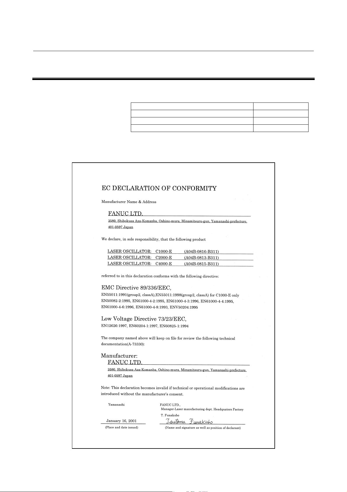
And, these models conform with EMC Directive 89/336/EEC, and
Low Voltage Directive 73/23/EEC.
p-1
Page 4

B-70314EN/01 TABLE OF CONTENTS
TABLE OF CONTENTS
PREFACE
PREFACE................................
PREFACEPREFACE
1111 OVERVIEW
................................................................
................................................................
OVERVIEW................................
OVERVIEWOVERVIEW
................................................................
................................................................
................................................................
................................................................
................................................................
................................................................
................................................................
................................................................
................................................................
................................................................
................................................
................................................................
................ p-
................................
.........................................
................................................................
......... 1111
..................
p-1111
p-p-
1.1
1.2
1.3
1.4
1.5
2222 SAFETY
2.1
2.2
2.3
2.4
2.5
2.6
2.7
2.8
2.9
2.10
MANUAL CONTENTS ..................................................................................................................... 2
APPLICABLE MODELS................................................................................................................... 3
RELATED MANUALS...................................................................................................................... 4
FOR SAFE OPERATION.................................................................................................................. 5
NOTES ON READING THIS MANUAL ......................................................................................... 6
SAFETY ................................
SAFETYSAFETY
................................................................
................................................................
LASER BEAM ................................................................................................................................... 8
HIGH VOLTAGE............................................................................................................................. 13
SAFETY ENCLOSURE (AT YOUR WORK STATION) ............................................................... 17
FIRE ................................................................................................................................................. 18
TOXIC FUME.................................................................................................................................. 19
HIGH TEMPERATURE.................................................................................................................. 20
WARNING LABELS ....................................................................................................................... 24
HIGH-PRESSURE GAS.................................................................................................................. 35
KEY CONTROL............................................................................................................................... 36
SHUTTER LOCK ............................................................................................................................ 37
................................................................
................................................................
................................................................
................................................................
..............................................
................................................................
.............. 7777
............................
2.11
2.12
2.13
3333 INSTALLATION
3.1
EMERGENCY STOP BUTTON ..................................................................................................... 38
WARNING LIGHT (OPTIONAL)................................................................................................... 39
INAPPOSITE USE OF LASER OSCILLATOR............................................................................. 40
INSTALLATION ................................
INSTALLATIONINSTALLATION
CONDITION.................................................................................................................................... 42
................................................................
................................................................
................................................................
................................................................
...............................................................
................................................................
............................... 41
..............................................................
3.1.1 Environmental Conditions ...................................................................................................... 42
3.1.2 Power Source............................................................................................................................ 42
3.1.3 Laser Gas.................................................................................................................................. 42
3.1.4 Cooling Water .......................................................................................................................... 43
3.2
TRANSPORTATION....................................................................................................................... 45
3.2.1 Lifting Laser Oscillator ........................................................................................................... 45
3.2.2 Packing ..................................................................................................................................... 46
3.2.3 Environmental Condition........................................................................................................ 50
3.3
STORAGE ........................................................................................................................................ 51
3.3.1 Environmental Condition........................................................................................................ 51
41
4141
c - 1
Page 5

TABLE OF CONTENTS B-70314EN/01
3.4
3.5
3.6
BASE OF OSCILLATOR ........................................................................................................................ 52
MAINTENANCE AREA ................................................................................................................. 54
WATER CONNECTION ................................................................................................................. 57
3.6.1 Chiller....................................................................................................................................... 57
3.6.2 Cooling Water Temperature ................................................................................................... 58
3.6.3 Cooling Water Flow Rate ........................................................................................................ 58
3.6.4 Plumbing .................................................................................................................................. 58
3.7
LASER GAS..................................................................................................................................... 59
3.7.1 Gas Bottle................................................................................................................................. 59
3.7.2 Laser Gas Tubing..................................................................................................................... 59
3.7.3 Gas Pipe.................................................................................................................................... 59
3.8
LASER BEAM ................................................................................................................................. 61
3.8.1 Position and Tolerance of Laser Beam Exit ........................................................................... 61
3.8.2 Beam Divergence ..................................................................................................................... 62
3.8.3 Tolerance of Beam Direction ................................................................................................... 62
3.8.4 Beam Guide.............................................................................................................................. 62
3.9
ELECTRIC CONNECTION............................................................................................................ 63
3.9.1 Power Cable (L1, L2, L3)......................................................................................................... 65
3.9.2 Ground Cable ........................................................................................................................... 65
3.9.3 I/O Signal Cable ....................................................................................................................... 65
3.9.4 Other Signal Cables to the IF PCB......................................................................................... 66
3.9.5 Safety Interlock........................................................................................................................ 67
3.9.6 EMC Countermeasure............................................................................................................. 71
4444 FUNCTIONS
FUNCTIONS................................
FUNCTIONSFUNCTIONS
4.1
INTERNAL STRUCTURE..............................................................................................................73
................................................................
................................................................
................................................................
................................................................
................................................................
................................................................
.....................................
................................................................
4.1.1 Outline...................................................................................................................................... 76
4.2
4.3
4.4
5555 MAINTENANCE
5.1
5.2
COMPONENT DETAILS................................................................................................................ 78
OPERATION SEQUENCE .............................................................................................................85
LASER PROCESSING MACHINE SYSTEM................................................................................ 88
MAINTENANCE ................................
MAINTENANCEMAINTENANCE
DAILY INSPECTION ..................................................................................................................... 91
PERIODIC MAINTENANCE ......................................................................................................... 92
................................................................
................................................................
................................................................
................................................................
..............................................................
................................................................
.............................. 90
............................................................
..... 72
72
..........
7272
90
9090
5.3
DETAILS OF MAINTENANCE ..................................................................................................... 93
5.3.1 Maintenance Panels and Oil Gauge Position......................................................................... 93
5.3.2 Turbo Blower Oil...................................................................................................................... 97
5.3.3 Exhaust Pump Oil ................................................................................................................... 99
c - 2
Page 6

B-70314EN/01 TABLE OF CONTENTS
5.3.4 Exhaust Pump Filter ............................................................................................................. 100
5.4
AGING ........................................................................................................................................... 101
5.4.1 Leak Check Method ............................................................................................................... 101
5.4.2 Aging Method ......................................................................................................................... 102
5.5
MAINTENANCE PARTS.............................................................................................................. 104
5.5.1 Spare Parts............................................................................................................................. 104
5.5.2 Maintenance Tools................................................................................................................. 105
6666 TROUBLESHOOTING
TROUBLESHOOTING ................................
TROUBLESHOOTINGTROUBLESHOOTING
6.1
6.2
APPENDIX
APPENDIX
APPENDIXAPPENDIX
AAAA EXTERNAL VIEW OF LASER OSCILLATOR
BBBB SPECIFICATIONS
CCCC ERROR CODE LIST
CHECKING ON FAULTS ............................................................................................................ 107
RESPONDING TO ALARM MESSAGES ON THE SCREEN ................................................... 108
EXTERNAL VIEW OF LASER OSCILLATOR................................
EXTERNAL VIEW OF LASER OSCILLATOREXTERNAL VIEW OF LASER OSCILLATOR
SPECIFICATIONS ................................
SPECIFICATIONSSPECIFICATIONS
ERROR CODE LIST ................................
ERROR CODE LISTERROR CODE LIST
................................................................
................................................................
................................................................
................................................................
................................................................
................................................................
................................................................
................................................................
................................................................
................................................................
................................................................
................................................................
................................................................
................................................................
...................................................
................................................................
..............................................
................................................................
.........................................................
................................................................
.......................................................
................................................................
................... 106
......................................
.............. 123
............................
......................... 126
..................................................
....................... 127
..............................................
106
106106
123
123123
126
126126
127
127127
DDDD FANUC SERVICE NETWORK
FANUC SERVICE NETWORK ................................
FANUC SERVICE NETWORKFANUC SERVICE NETWORK
EEEE GLOSSARY
GLOSSARY ................................
GLOSSARYGLOSSARY
................................................................
................................................................
................................................................
................................................................
................................................................
................................................................
................................................................
................................................................
................................................................
................................................................
......................................
................................................................
.....................................
................................................................
...... 128
128
............
128128
..... 129
129
..........
129129
c - 3
Page 7

B-70314EN/01 1.OVERVIEW
1 OVERVIEW
In this manual, we have tried as for as possible to address all issues.
However, space restrictions prevent us from describing everything
that must not be done, or which cannot be done, because there are so
many possibilities.
Therefore, all matters which are not specifically described as being
possible should be regarded as being "impossible".
Contents of this chapter
1.1 MANUAL CONTENTS .............................................................. 2
1.2 APPLICABLE MODELS............................................................ 3
1.3 RELATED MANUALS............................................................... 4
1.4 FOR SAFE OPERATION ........................................................... 5
1.5 NOTES ON READING THIS MANUAL................................... 6
- 1 -
Page 8

1.OVERVIEW B-70314EN/01
1.1 MANUAL CONTENTS
This manual consists of the following chapters and appendixes:
1. OVERVIEW
Chapter 1 covers the configuration of the manual, applicable
models, related manuals, and provides notes on reading the
manual.
2. SAFETY
Chapter 2 covers the warnings and precautions related to laser
beams, high voltages, high temperatures, and a toxic substances.
To ensure safe operation, read this chapter first.
3. INSTALLATION
Chapter 3 describes the condition for installation and connection
of electrical cables, water tubes, gas tubes.
4. FUNCTIONS
Chapter 4 describes the structure and operation of the laser
oscillator.
5. MAINTENANCE
Chapter 5 describes the periodic maintenance of the laser
oscillator.
6. TROUBLESHOOTING
Chapter 6 describes the actions to be taken if the oscillator
malfunctions.
APPENDIX
A. EXTERNAL VIEW
B. FANUC LASER C SERIES SPECIFICATIONS
C. ERROR CODE LIST
D. FANUC SERVICE NETWORK
E. GLOSSARY
- 2 -
Page 9

B-70314EN/01 1.OVERVIEW
1.2 APPLICABLE MODELS
This manual covers the following models:
Model Abbreviation
FANUC LASER C1000-MODEL E C1000-E
FANUC LASER C2000-MODEL E C2000-E
FANUC LASER C4000-MODEL E C4000-E
- 3 -
Page 10

1.OVERVIEW B-70314EN/01
1.3 RELATED MANUALS
The following manuals are available for the FANUC LASER C1000/
C2000/C4000-MODEL E :
DESCRIPTIONS B-63192EN
CONNECTION MANUAL B-63193EN
FANUC Series 16i-LA
FANUC LASER
C1000/C2000/C4000-MODEL E
OPERATOR’S MANUAL B-63194EN
MAINTENANCE MANUAL B-63195EN
PARAMETER MANUAL B-63200EN
OPERATOR’S MANUAL
(This manual)
MAINTENANCE MANUAL B-70315EN
B-70314EN
- 4 -
Page 11
B-70314EN/01 1.OVERVIEW
1.4 FOR SAFE OPERATION
This manual contains precautions which must be observed during
operation of the laser oscillator, to ensure the operator's safety and
prevent damage to the oscillator. Each precaution is indicated by
"Warning" or "Caution" according to its severity.
Supplementary information is indicated by "Note".
Read the contents of each "Warning", "Caution", and "Note" before
attempting to use the oscillator.
WARNING
Precautions to be applied in those situations where
there is a danger of the operator being killed or
seriously injured.
CAUTION
Precautions to be applied in those situations where
there is a danger of the operator being slightly
injured or the oscillator being damaged.
NOTE
Supplementary information other than precautions.
- 5 -
Page 12

1.OVERVIEW B-70314EN/01
1.5 NOTES ON READING THIS MANUAL
The functions of a laser machining system depend not only on the
laser oscillator, but also on the machine, power magnetics cabinet,
servo system, CNC, and operator's panel. This manual describes only
the laser oscillator. For a description of the other components, refer to
the corresponding manuals, supplied by the machine tool builder.
Read this manual thoroughly and store it in a safe place.
- 6 -
Page 13

B-70314EN/01 2.SAFETY
2 SAFETY
C1000-E, C2000-E, and C4000-E produce the rated output laser
power of 1000W, 2000W, and 4000W. The CO
wavelength of 10.6 µm, far infrared, and is invisible to human eyes.
The adequate care must be taken when CO
therefore. When removing the panel, always turn the power source off
and confirm no power is applied to the laser machine.
This oscillator fulfills the requirements of the relevant product safety
standard of EN60825-1:1994.
laser beam is the
2
laser is operated,
2
- 7 -
Page 14

2.SAFETY B-70314EN/01
2.1 LASER BEAM
1) Potential hazards
Laser oscillator emits CO
power and invisible.
• Being directly exposed to the CO
burn you.
• The CO
beam could bource off your workpiece and burn
2
your eyes or skin.
LASER oscillator have a guide laser. The guide laser beam
is visible (red color) and low power. It is used to ensure that
the CO
beam is correctly positioned on your workpiece.
2
• The diode laser beam is not considered harmful to your skin.
But if you stared head on into the guide laser beam, it could
harm your eyes.
2) Safety recommendations
Never expose the eyes and skin to the laser beam. Be careful of
the laser beam when performing the inspection and maintenance.
Do not turn on the power supply to the oscillator when the panel
open and do not drive. It is bleached to radiation of the laser
beam and high voltage.
Do the countermeasure (For instance, installs safety glasses and
the protection gloves) to danger in case of stopped no finish and
nor opening the panel while it energizes the oscillator.
Install beam safety cover after mirror cleaning or replacement.
And if not beam safety cover installation, do not operation and
alignment.
Confirm when it does alignment, the protection pipe (Safety
cover) is installed. If it dose not install the protection pipe, it will
put the finger in the laser beam and there is possibility to do the
burn.
When entering the area exposed to the scattered beam, wear the
safety glasses. Mount the stand made of acrylic resin or any
material which can absorb the CO
personnel from the scattered beam.
Avoid exposure of any part of your body to the CO
When testing the beam output, any personnel other than the
maintenance personnel should be out of the working
environment.
In designing a material processing machine utilizing laser
oscillator, be sure that the CO
workpiece only through the enclosed beam delivery system. This
prevents the exposure to laser beam by the operator switch could
otherwise take place. It is absolutely necessary to include the
instructions given here in the manuals of the laser materialprocessing machine as a whole, which are to be read.
laser beam(10.6 µm), which is high
2
beam could severely
2
laser beam to protect the
2
laser beam.
2
laser beam goes from laser to the
2
- 8 -
Page 15

B-70314EN/01 2.SAFETY
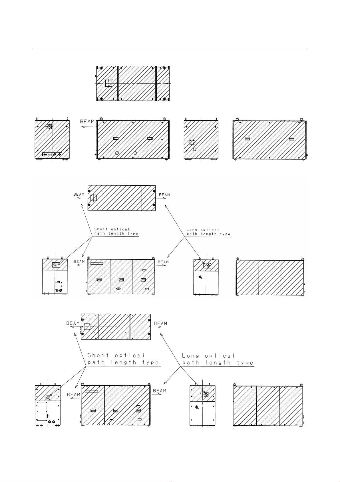
3) Position of laser beam emission
Fig.2.1(a) is the position of panel that laser beam exposure is
occurred without panel in C1000-E, when your maintenance.
Fig.2.1(b) is the position of panel that laser beam exposure is
occurred without panel in C2000-E, when your maintenance.
Fig.2.1(c) is the position of panel that laser beam exposure is
occurred without panel in C4000-E, when your maintenance.
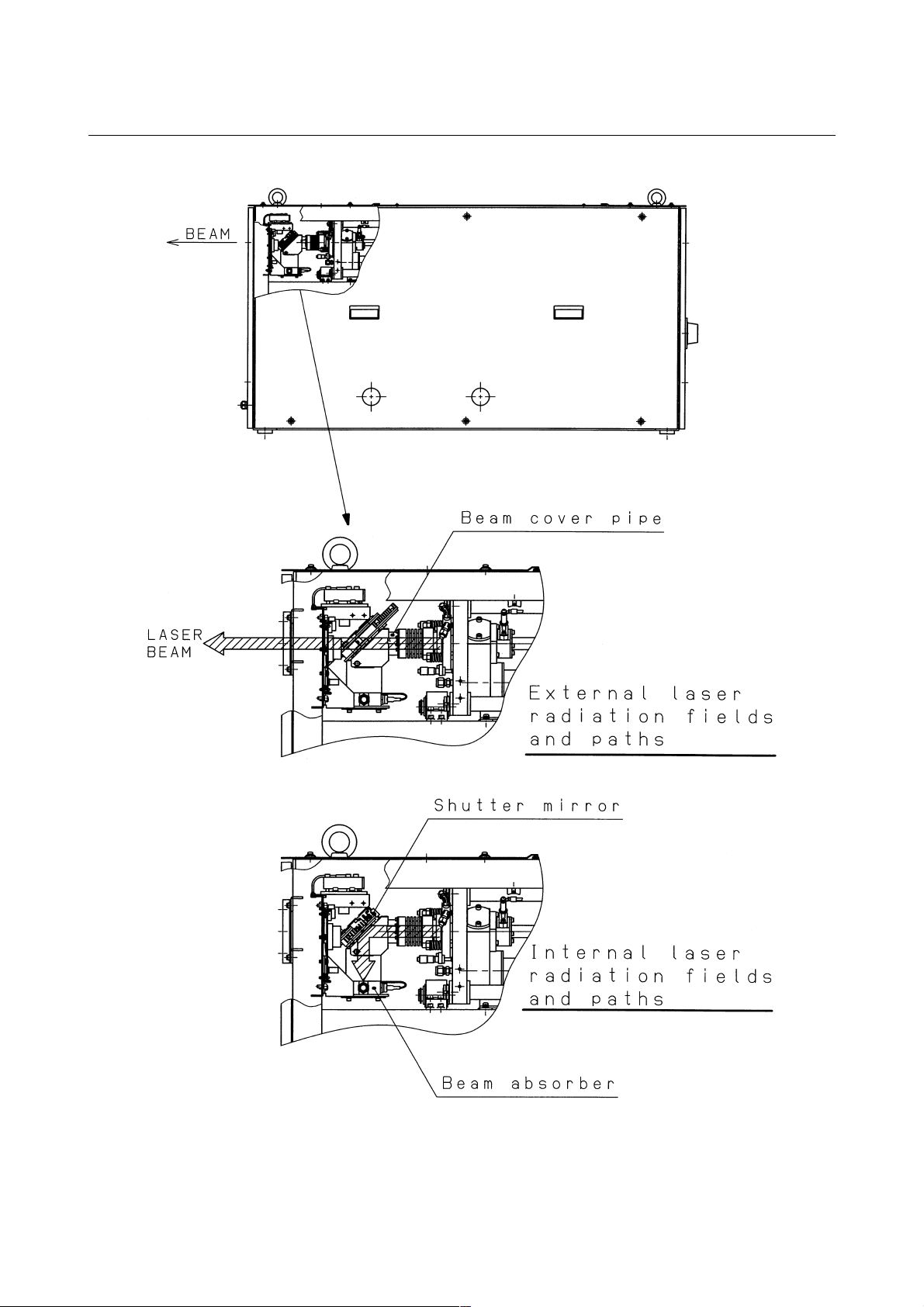
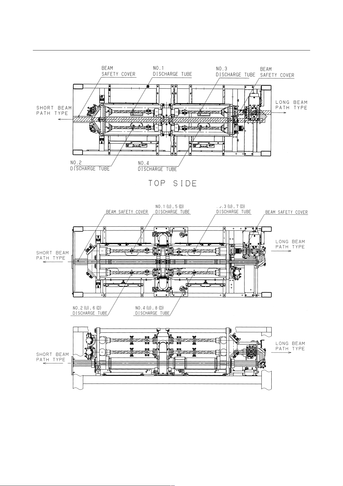
Fig.2.1(d) is the position of laser beam delivery in C1000-E.
Fig.2.1(e) is the position of laser beam delivery in C2000-E.
Fig.2.1(f) is the position of laser beam delivery in C4000-E.
- 9 -
Page 16
2.SAFETY B-70314EN/01
Fig.2.1(a) Laser beam exposure position without panel as operating (C1000-E)
Fig.2.1(b) Laser beam exposure position without panel as operating (C2000-E)
Fig.2.1(c) Laser beam exposure position without panel as operating (C4000-E)
- 10 -
Page 17
B-70314EN/01 2.SAFETY
Fig.2.1(d) The position of laser beam delivery (C1000-E)
- 11 -
Page 18
2.SAFETY B-70314EN/01
Fig.2.1(e) The position of laser beam delivery (C2000-E)
Fig.2.1(f) The position of laser beam delivery (C4000-E)
- 12 -
Page 19

B-70314EN/01 2.SAFETY
2.2 HIGH VOLTAGE
1) Potential hazards
There is RF voltage of 3 to 4kVo-p in the cabinet of the laser
oscillator.
There is 200 VAC power in the relay panel, be careful not to
touch the high voltage.
2) Safety recommendations
When it checks the oscillator and exchange the unit, intercept a
main breaker of the oscillator and the power supply. Lock the
breaker to prevent misconnection and display the sign while
working.
Install safety cover after unit replacement or cable connection.
Unless safety cover is installed, never perform operation.
Follow standard industrial safety practices for working with high
voltage.
EXAMPLES
• Do not work on the laser oscillator if you are tired or have
taken medicine.
• Do not wear anything metal, like a ring, bracelet, watch,
belt buckle, earrings, or keys.
• They might contact high voltage.
• Never stand on a wet surface.
• Do not touch electrical components in the cabinets with
both hands at once. Keep one hand in a pocket.
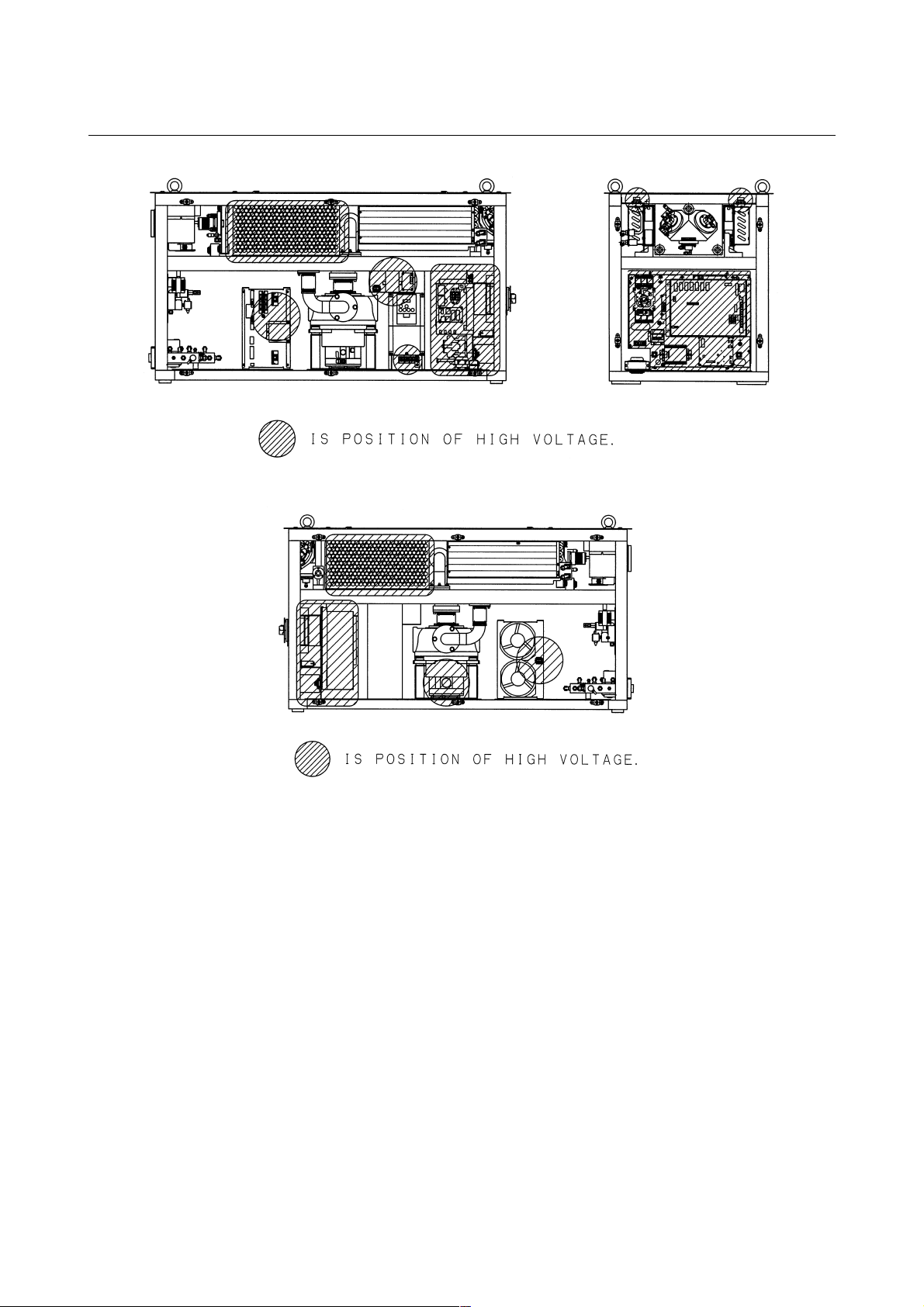
3) Position of high voltage
Fig.2.2(a) is the position of high voltage in C1000-E (Front,
maintenance side).
Fig.2.2(b)is the position of high voltage in C1000-E (Back side).
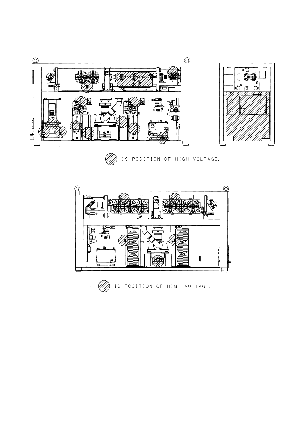
Fig.2.2(c) is the position of high voltage in C2000-E (Front,
maintenance side).
Fig.2.2(d)is the position of high voltage in C2000-E (Back side).
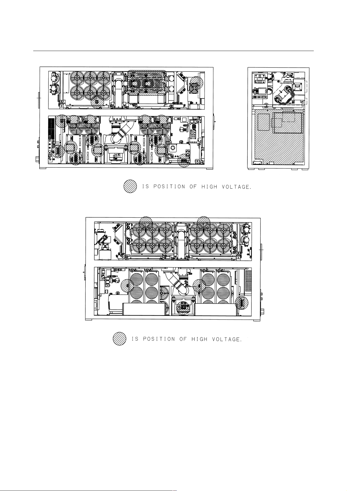
Fig.2.2(e) is the position of high voltage in C4000-E (Front,
maintenance side).
Fig.2.2(f) is the position of high voltage in C4000-E (Back side).
- 13 -
Page 20
2.SAFETY B-70314EN/01
Fig.2.2(a) Position of high voltage in C1000-E (Front, maintenance side)
Fig.2.2(b) Position of high voltage in C1000-E (Back side)
- 14 -
Page 21
B-70314EN/01 2.SAFETY
Fig.2.2(c) Position of high voltage in C2000-E (Front, maintenance side)
Fig.2.2(d) Position of high voltage in C2000-E (Back side)
- 15 -
Page 22
2.SAFETY B-70314EN/01
Fig.2.2(e) Position of high voltage in C4000-E (Front, maintenance side)
Fig.2.2(f) Position of high voltage in C4000-E (Back side)
- 16 -
Page 23

B-70314EN/01 2.SAFETY
2.3 SAFETY ENCLOSURE (AT YOUR WORK STATION)
1) Potential hazards
CO
beam is delivery from oscillator. Direct or scattered beam is
2
exposed.
2) Safety recommendations
Mount the safety enclosure made of acrylic resin which can
absorb the laser beam around the working environment.
Mount the interlock switch on the safety enclosure door which
extinguishes the laser beam output when the door is open. Never
perform operation without safety cover of laser machine.
- 17 -
Page 24

2.SAFETY B-70314EN/01
2.4 FIRE
1) Potential hazards
When you work with the laser oscillator or machine, hot
fragments or slag can scatter from your workpiece. The CO
beam or a reflection of it could ignite flammable material.
2) Safety recommendations
The direct or scattered laser beam can ignite flammable materials
such as paper, cloth, and wood. Provide a beam absorber behind
the workpiece and around it during maintenance. The absorber
can be anodized aluminum, graphite or brick.Put a shield
between yourself and the workpiece when the CO
Even diffuse reflections can harm eyes and skin and may ignite
flammable material.
beam is on.
2
2
- 18 -
Page 25

B-70314EN/01 2.SAFETY
2.5 TOXIC FUME
1) Potential hazards
Some materials such as certain plastics can emit toxic fume
when they burn under the laser beam.
2) Safety recommendations
Install the exhaust system to remove toxic fume from the work
environment.
Consult the manufacturer of the material you are processing to
learn if it creates any fumes when heated or burned.
- 19 -
Page 26

2.SAFETY B-70314EN/01
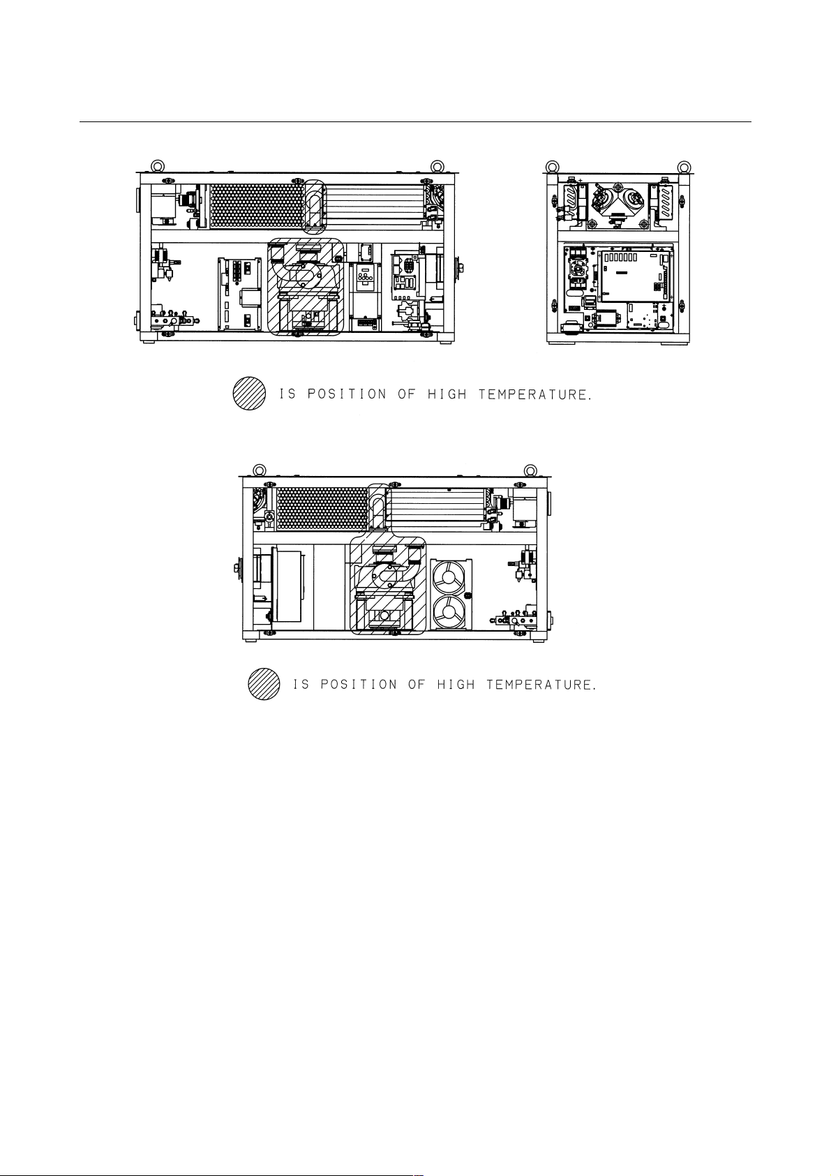
2.6 HIGH TEMPERATURE
1) Potential hazards
When you touch a part of high temperature, your skin burn.
2) Safety recommendations
The pipes of the gas circular system are very a high temperature.
Do not touch pipes, heat exchanger and turbo blower because it
does not do the burn. It is hot immediately after having stopped
driving. After getting cold enough in case of removing, dismount
it.
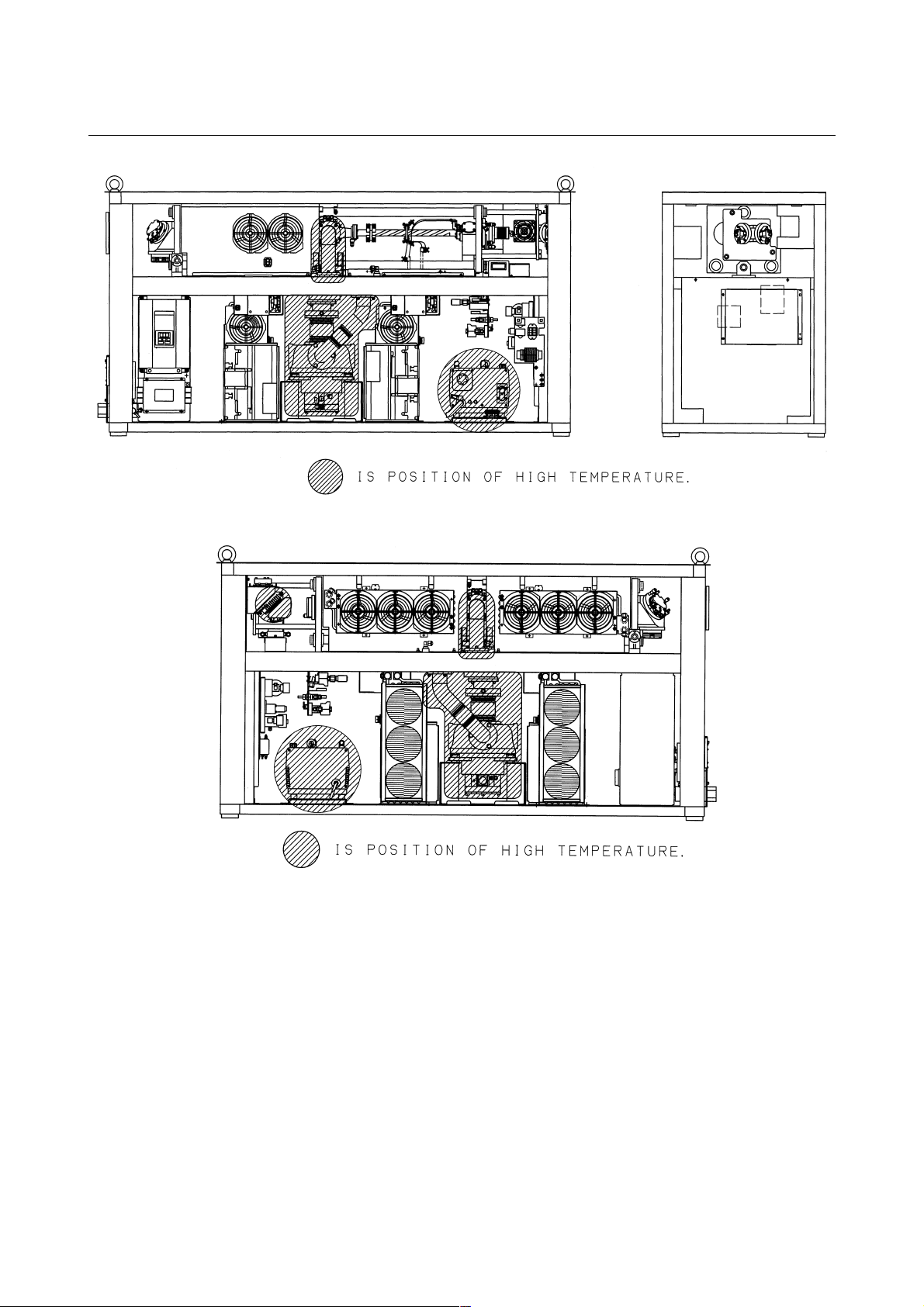
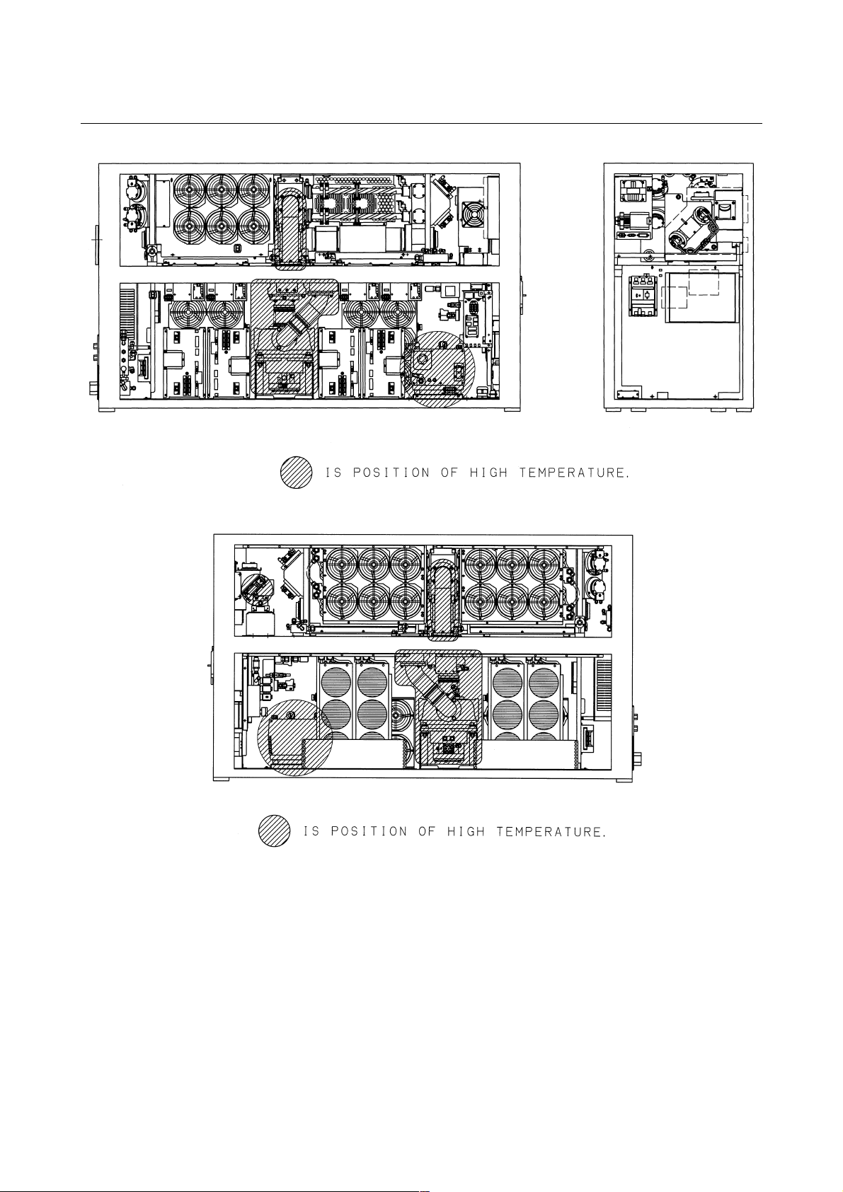
3) Position of high temperature
Fig.2.6(a) is the position of high temperature in C1000-E (Front,
maintenance side).
Fig.2.6(b) is the position of high temperature in C1000-E (Back
side).
Fig.2.6(c) is the position of high temperature in C2000-E (Front,
maintenance side).
Fig.2.6(d) is the position of high temperature in C2000-E (Back
side).
Fig.2.6(e) is the position of high temperature in C4000-E (Front,
maintenance side).
Fig.2.6(f) is the position of high temperature in C4000-E (Back
side).
- 20 -
Page 27
B-70314EN/01 2.SAFETY
Fig.2.6(a) Position of high temperature in C1000-E (Front, maintenance side).
Fig.2.6(b) Position of high temperature in C1000-E (Back side).
- 21 -
Page 28
2.SAFETY B-70314EN/01
Fig.2.6(c) Position of high temperature in C2000-E (Front, maintenance side).
Fig.2.6(d) Position of high temperature in C2000-E (Back side).
- 22 -
Page 29
B-70314EN/01 2.SAFETY
Fig.2.6(e) Position of high temperature in C4000-E (Front, maintenance side).
Fig.2.6(f) Position of high temperature in C4000-E (Back side).
- 23 -
Page 30

2.SAFETY B-70314EN/01
2.7 WARNING LABELS
Fig.2.7(a)-(f) show the location of the warning labels indicating the
high voltage and laser beam path.
Fig.2.7(a) is the location of the warning sticker (C1000-E:Front side).
Fig.2.7(b) is the location of the warning sticker (C1000-E:Back side).
Fig.2.7(c) is the location of the warning sticker (C2000-E:Front side).
Fig.2.7(d) is the location of the warning sticker (C2000-E:Back side).
Fig.2.7(e) is the location of the warning sticker (C4000-E:Front side).
Fig.2.7(f) is the location of the warning sticker (C4000-E:Back side).
- 24 -
Page 31

B-70314EN/01 2.SAFETY
Fig.2.7(a) Location of the warning sticker (C1000-E:Front side).
Fig.2.7(b) Location of the warning sticker (C1000-E:Back side).
- 25 -
Page 32

2.SAFETY B-70314EN/01
Fig.2.7(c) Location of the warning sticker (C2000-E:Front side).
Fig.2.7(d) Location of the warning sticker (C2000-E:Back side).
- 26 -
Page 33

B-70314EN/01 2.SAFETY
Fig.2.7(e) Location of the warning sticker (C4000-E:Front side).
Fig.2.7(f) Location of the warning sticker (C4000-E:Back side).
- 27 -
Page 34

2.SAFETY B-70314EN/01
Detail of warning sticker
(1) Warning logotype (C1000-E)
(1) Warning logotype (C2000-E, C4000-E)
- 28 -
Page 35

B-70314EN/01 2.SAFETY
(2) Warning logotype
(3) Label for defeasible non-interlocked protective housing
(4) Label for defeasible non-interlocked protective housing
(5) Caution label for lifting
- 29 -
Page 36

2.SAFETY B-70314EN/01
(6) Aperture label
(7) Label of non-interlocked protective panel
(8) Identification label
- 30 -
Page 37

B-70314EN/01 2.SAFETY
(9) Address label
(10) High voltage warning label
(11) Supply voltage label
(12) Label of over-current protective
- 31 -
Page 38

2.SAFETY B-70314EN/01
(13) Label of motor and transformer (C1000-E)
(13) Label of motor and transformer (C2000-E)
(13) Label of motor and transformer (C4000-E)
- 32 -
Page 39

B-70314EN/01 2.SAFETY
(14) Label of warning light
(15) Maintenance label
(16) Certification label
(17) Short-circuit interrupting capacity of main breaker (C1000-E)
(17) Short-circuit interrupting capacity of main breaker (C2000-E,
C4000-E)
- 33 -
Page 40

2.SAFETY B-70314EN/01
(18) Label for regurating the atmospheric gases in the oscillator
housing
(19) Label for cooling water and laser gas
- 34 -
Page 41

B-70314EN/01 2.SAFETY
2.8 HIGH-PRESSURE GAS
Do not allow any dangerous or high-pressure gas to get into the
oscillator housing. The oscillator cabinet has a hermetic structure
(dustproof and dripproof), it cannot be ventilated easily.
Flammable gases such as oxygen can cause a fire or explosion.
Toxic gases can harm operators during maintenance. Organic gases
can degrade machining performance. High-pressure gases can damage
a panel or the cabinet, resulting in injury from flying matters.
If such a gas accidentally gets into the oscillator housing, remove a
panel for ventilation. The installation room must be also well
ventilated.
To purge the oscillator housing, use purified, low-pressure air or
nitrogen.
- 35 -
Page 42

2.SAFETY B-70314EN/01
2.9 KEY CONTROL
All the laser products have to comply with the various kinds of laser
safety regulations, which include the use of key control. For instance,
FDA PART 1040 PERFORMANCE STANDARDS FOR LIGHTEMITTING PRODUCTS, Sec 1040. 10 (f), (4) states: "Each laser
system classified as a Class IIIb or IV laser product shall incorporate a
key-actuated master control. The key shall be removable and the laser
shall not be operable when the key is removed" and EN60825-1:1994,
4.5 Key control state "Any laser system belonging to one of the
following classes shall incorporate a key operation master control:
Class 4 and Class 3B, except for Class 3B with not more than five
times the AEL of Class 2 in the wavelength range from 400 nm to 700
nm. The key shall be removable and the laser radiation shall not be
accessible when the key is removed."
Because the laser package products offered by FANUC cannot
produce the laser beam as they are in the state of shipment, the system
integrator who incorporates FANUC products into the system, which
generates the laser beam, is obliged to incorporate the master key as
defined by the relevant regulation.
- 36 -
Page 43

B-70314EN/01 2.SAFETY
2.10 SHUTTER LOCK
The shutter lock is prepared because it dose not put out the laser beam
by mistake. If you do not put out the beam, lock the shutter.
Use the mechanical switch at shutter lock switch, not electrical
component (Relay)or switching circuit (Transistor, FET).
Use the one with the compulsion dissociation mechanism for the
switch used for the shutter lock circuit and the switch for welding
prevention.
To designer of laser processing machine
1 Use a mechanical switch for the switch used to lock
the shutter. Do not use an electric switch (For
instance, transistor circuit, etc.). Moreover, use the
one with the contact dissociation mechanism to
prevent welding for a mechanical switch.
2 Put it in the series of the contact of the emergency
stop button in the shutter lock circuit. When the
emergency stop switch is pushed, it is necessary to
intercept the power supply to the shutter.
- 37 -
Page 44

2.SAFETY B-70314EN/01
2.11 EMERGENCY STOP BUTTON
Press the emergency stop button when it is dangerous and breaks
down. The oscillator is stopped discharging, gas pressure control and
stand by purge state.
Use the one with the compulsion dissociation mechanism for the relay
used for the emergency stop circuit and the switch for welding
prevention.
- 38 -
Page 45

B-70314EN/01 2.SAFETY
2.12 WARNING LIGHT (OPTIONAL)
Laser oscillator is equipped with the warning light optionally. The
light is flashed during discharging and ready of laser beam emission.
Be careful of laser beam and high voltage.
To designer of laser processing machine
In EN60825-1, it needs the design with the fail safe
or redundant for warning equipment. The redundant
warning light is needed near the work-point of
processing machine. The warning light is prepared
for the oscillator. Select this as a warning light more
than the second for the fail safe.
- 39 -
Page 46

2.SAFETY B-70314EN/01
2.13 INAPPOSITE USE OF LASER OSCILLATOR
Inapposite use and the result are described in each explanation place.
Inapposite major use are described in the following.
(1) The gas with different composition and purity from the
specification is connected with the oscillator.
The oscillator does not work normally and do the protection
movement. In the worst case, the oscillator breaks down.
(2) The gas piping with different material and structure from the
specification is used.
A leakage of the laser gas and a defective composition are
occurred. In the worst case, the oscillator breaks down.
(3) The water piping of the material, which corrodes to water, is
used.Water is blocked by the generation of rust. If cooling water
does not flow in a regulated amount, the oscillator will not work
normally.
(4) Cooling water is not regularly exchanged.
Water is blocked by the generation of rust. Moreover, it is easy
for the water fittings in the oscillator to corrode. In the worst
case, the fittings are damaged and the water leak happens.
(5) The oil of turbo blower and the exhaust pump is not regularly
exchanged.
Turbo blower is damaged and the oscillator does not work. The
exhaust pump is damaged similarly.
(6) The filter of the exhaust pump is not regularly exchanged.
The exhaust ability of the exhaust pump decreases. Moreover,
white smoke comes out from the pump exit and the oil leak
happens. In the worst case, the oscillator does not work.
(7) You will touch an unrelated place when usually maintaining.
In the oscillator there are adjustment place. The adjustment place
is the best value when shipping. When the adjustment shifts, the
oscillator will not work normally. It is necessary to adjust it by
service man that was trained.
(8) You open the panel immediately after the oscillator was stopped
and oil is exchanged.
(9) There is a place of the high temperature immediately after the
oscillator stopped. When you touches there, you will do the burn.
After getting cold of the oscillator, open the panel. Refer to
safety in Chapter 2 for the place of the high temperature.
- 40 -
Page 47

B-70314EN/01 3.INSTALLATION
3 INSTALLATION
- 41 -
Page 48

3.INSTALLATION B-70314EN/01
3.1 CONDITION
3.1.1 Environmental Conditions
(1) Ambient
+5 to 30°C
(2) Temperature drift
Max 1.1°C/min
(3) Humidity
< 75% (relative)
(4) Vibration
Acceleration < 0.05G
Amplitude < 5µm
(5) Atmosphere
Free from dust and volatile vapor
3.1.2 Power Source
3.1.3 Laser Gas
(1) Input power and maximum current
Model Power Maximum current
C1000-E 18 KVA 60 A
C2000-E 33 KVA 110 A
C4000-E 55 KVA 190 A
(2) Voltage
200VAC+10%, -15%, 50/60Hz ± 1Hz, 3φ
or 220VAC+10%, -15%, 60Hz ± 1Hz, 3φ
(3) Earth-ground
Ground (<10 ohm)
Protective earth (PE)
For the laser gas, the following specifications are required.
(1) Composition and its accuracy
CO
:5±0.25% Purity > 99.99%
2
He : 40±2.00% > 99.99%
N
:55±2.75% (Balance) > 99.99%
2
(2) Water vapor (H
(3) Hydrocarbon (CmHn) < 1ppm
- 42 -
O) < 5ppm
2
Page 49

B-70314EN/01 3.INSTALLATION
3.1.4 Cooling Water
(1) Cooling water specification
The quality of cooling water is specified in the table below. If
tap water is used, it should be treated in an ion exchanger.
Refrigerator/air-conditioner cooling water quality standard
(JRA-9001-1980)
pH (25°C) 6.0 to 8.0
Conductivity (25°C) (µs/cm) 200 or less
Standard item
Reference
item
(2) Anticorrosive
To avoid cooling water trouble and minimize the frequency of
cooling water exchange, the following anticorrosive should be
added to the cooling water.
Consult the chiller manufacturer for use of the anticorrosive.
Product name: CONTLIME K-6000
Manufacturer: MITSUBISHI GAS CHEMICAL. ISC
Use: Refer to the description indicated on the product.
Replace the cooling water every year, even if an anticorrosive
has been added to it.
Chlorine ion Cl- (ppm) 20 or less
Sulfate ion SO
M alkalinity CaCO3 (ppm) 50 or less
Total hardness CaCO
Iron Fe (ppm) 0.3 or less
Sulfur ion S2- (ppm) Not to be detected
Ammonia ion NH
Ionic silica SiO
2-
(ppm) 50 or less
4
(ppm) 50 or less
3
+
(ppm) 0.2 or less
4
(ppm) 30 or less
2
(3) Cleaning agent
The following cleaning agent should be used. Consult the
chiller manufacturer for use of the cleaning agent.
Product name: DESLIME
Manufacturer: MITSUBISHI GAS CHEMICAL ISC
Use: Refer to the description indicated on the product.
(4) Antifreezing solution
If the chiller is used in a cold district, it should be provided with
an antifreezing function. When it is extremely cold, the chiller
should be kept running. If it is necessary to use an antifreezing
solution for lack of an alternative, the following antifreezing
solution should be used. Its concentration should be 30%
(usually) or 40% (in an extremely cold district). Use of an
antifreezing solution should be restricted within four months in
winter. Do not use antifreezing solution together with an
anticorrosive. The following antifreezing solution is already
added with an anticorrosive.
Product name: AURORA BRINE
Manufacturer: TOKYO FINE CHEMICAL Co.
Use: Refer to the description indicated on the product.
- 43 -
Page 50

3.INSTALLATION B-70314EN/01
CAUTION
In winter or in a cold district, when the oscillator is at
a rest and the ambient temperature gets to or below
the freezing point, the cooling water in the oscillator
freezes, possibly breaking the water pipe or
damaging the chilling unit. When the oscillator is not
in use, drain cooling water from it. To drain water,
keep blowing compressed air at 0.5 MPa or less into
the oscillator through the cooling water inlet for 15
minutes.
- 44 -
Page 51

B-70314EN/01 3.INSTALLATION
3.2 TRANSPORTATION
3.2.1 Lifting Laser Oscillator
In lifting the laser oscillator, be sure to use the four eyebolts screwed
into the top surface of the cabinet as shown in the figure. Never lift
using only the two bolts. The weight is shown following tables. The
permissible impact value of the oscillator is 2G. When the impact
which exceeds the permissible impact value is given, the resonator
will warp and the shape of the beam mode worsens.
- 45 -
Fig.3.2.1 Method of lifiting
Page 52

3.INSTALLATION B-70314EN/01
3.2.2 Packing
1) Clamp
When shipped from FANUC, the two components of the laser
listed below are in the clamped position. Because this is for
shipment only, remove the clamp during the installation. Be sure
to use the clamp, when the machine is shipped again. (1) Optical
resonator (2) Mechanical shutter.
Fig.3.2.2(a)-(c) are clamp layout.
CAUTION
If the machine is not damped during transportation,
the optical resonator may cause distortion or mat be
damaged.
- 46 -
Page 53

B-70314EN/01 3.INSTALLATION
Fig.3.2.2(a) Clamp layout (C1000-E)
- 47 -
Page 54

3.INSTALLATION B-70314EN/01
Fig.3.2.2(b) Clamp layout (C2000-E)
- 48 -
Page 55

B-70314EN/01 3.INSTALLATION
Fig.3.2.2(c) Clamp layout (C4000-E)
- 49 -
Page 56

3.INSTALLATION B-70314EN/01
2) Water
Be sure to drain water in the oscillator at shipment.
Refer to the maintenance manual for draining.
CAUTION
If water remains in the oscillator, internal water pipes
may be damaged in cold climates.
3.2.3 Environmental Condition
(1) Temperature
-20 to 50°C
CAUTION
Must be completed to drain in the oscillator. If water
remain in the oscillator, water freeze during the
transportation at cold district. Therefore oscillator is
damaged.
(2) Humidity 75% (relative)
(3) Vibration
Acceleration 0.05G
Amplitude 5mm
(4) Atmosphere
Free from the dust and the volatile vapor
- 50 -
Page 57

B-70314EN/01 3.INSTALLATION
3.3 STORAGE
The various kinds of clamps should be used only during the
transportation. Especially the clamps used for resonator should be
loosened during the storage. Storing the resonator as fixed with the
clamps for a long time will cause its distortion. The clamps are
provided for cavity, shutter unit.
Do not keep the oscillator in the place of the high temperature
humidity. Otherwise, it generates rust in the resonator.
3.3.1 Environmental Condition
(1) Temperature
-20 to 50°C
CAUTION
Must be completed to drain in the oscillator. If water
remain in the oscillator, water freeze during the
transportation at cold district. Therefore oscillator is
damaged.
(2) Humidity < 75% (relative)
(3) Vibration
Acceleration < 0.05G
Amplitude < 5mm
(4) Atmosphere
Free from the dust and the volatile vapor
(5) Location
Plain, no slope
- 51 -
Page 58

3.INSTALLATION B-70314EN/01
3.4 Base of oscillator
In laser oscillator, the two type of that is the four taps and hole are
prepared in the base as shown in the figure for fixing the laser cabinet
against the machine base.
Fig.3.4(a) Mounting (A)
Fig.3.4(b) Mounting (B)
- 52 -
Page 59

B-70314EN/01 3.INSTALLATION
Fig.3.4(c) Cabinet base (C1000-E)
Fig.3.4(d) Cabinet base (C2000-E, C4000-E)
- 53 -
Page 60

3.INSTALLATION B-70314EN/01
3.5 MAINTENANCE AREA
The maintenance areas of laser oscillator series are shown in the
figures below.
The customer is requested to prepare adequate space around the laser
even for the sides, which are not requested in the figures.
Fig.3.5(a) Maintenace area (C1000-E)
- 54 -
Page 61

B-70314EN/01 3.INSTALLATION
Fig.3.5(b) Maintenace area (C2000-E : Short type)
Fig.3.5(c) Maintenace area (C2000-E : Long type)
- 55 -
Page 62

3.INSTALLATION B-70314EN/01
Fig.3.5(d) Maintenace area (C4000-E : Short type)
Fig.3.5(e) Maintenace area (C4000-E : Long type)
- 56 -
Page 63

B-70314EN/01 3.INSTALLATION
3.6 WATER CONNECTION
3.6.1 Chiller
Make the cooling water re-circulate in the closed loop using a chiller
unit.
The cooling requirements of the chiller are as below.
(1) Chiller capacity
Type Capacity
C1000-E > 11 KW
C2000-E > 22.1 KW
C4000-E > 44.2 KW
(2) Temperature control range 20 to 30 °C
(3) Temperature accuracy ±1°C
(4) Water pressure 0.5 MPa or less
(5) Heat exhaust Water cooling or air cooling
(6) Attachment
• Water filter
• Water valve
• Flow switch
• Interface to externally switch of chiller
• Contact interface to send signal of normal operation of
chiller(CLRDY).
NOTE
Output the signal of "contact on" when everything is
normal with cooling water flow rate, temperature,
water level, overheat switch of chiller, high and low
pressure switch, over-current relay, etc.
- 57 -
Page 64

3.INSTALLATION B-70314EN/01
3.6.2 Cooling Water Temperature
Throughout the year, set the chiller water temperature to 27°C in
general regions and 30°C in humid regions.
3.6.3 Cooling Water Flow Rate
The flow rate should be chosen so that the temperature difference
between the inlet and outlet of the chiller becomes less than 3°C. The
customer can refer to the following table.
Type Flow rate
C1000-E 40 liters/min
C2000-E 75 liters/min
C4000-E 160 liters/min
3.6.4 Plumbing
The cooling water from chiller is temperature-regulated.
• Choose the tubing material which can withstand corrosion,
which will choke the water flow.
• Make the hose length between the laser and chiller as short as
possible. Along hose makes the pressure 1oss high and becomes
a burden to the chiller pump.
• Place a strainer at the water inlet of laser. It will prevent the
f1owing in of the dust into the laser.
• Place flow meters both at the inlet and outlet of the laser. Daily
checking of the water f1ow contributes to the prevention of
abrupt stop of laser operation.
The water fittings of the inlet and outlet of lasers are shown below.
- 58 -
Page 65

B-70314EN/01 3.INSTALLATION
3.7 LASER GAS
3.7.1 Gas Bottle
Use the gas bottle of the volume of 7m3. Store the necessary number
of bottles according to the operation of the laser.
3.7.2 Laser Gas Tubing
Drawing of last chapter 1 shown laser gas connection of inlet and
outlet. Inlet and outlet fittings on laser are female Rc 3/8".
(1) Gas inlet of oscillator
• Use the tube designated. (FANUC recommends the use of
AS1 tube or Poly-fro Tube manufactured by Jyunkosha or
Imperial Co. Ltd.)
Do not use a tube possessing high permeability to He. (In
the worst case, the laser will be damaged by improper gas
composition.)
• Use the gas of the correct composition.
3.7.3 Gas Pipe
(2) Gas outlet of oscillator
The oil mist and the dissociated gas come out from the exit of
the gas. Tie the piping of 3/8 inches or more to the gas exit and
put it out to outdoor.
It will load the exhaust pump when thin piping or extremely
1ong and the exhaust ability decreases occasionally.
Observe the following cautions for piping between the laser gas
cylinder and laser oscillator.
• Use nylon tube having an inside diameter of 8 mm or larger
(Junlon AS1 manufactured by Junkousha, or equivalent) or
polyethylene (Polyfro-tube). Do not use a rubber or urethane
tube.
• Use a swage-lock vacuum joint.
Do not use a one-touch coupler, quick coupler, or hose-band
joint.
• Minimize the length of tubing. It should be kept within 5 m.
Never exceed 15 m. For a length of 15 m or greater, use stainless
pipe.
• If it is necessary to use metal pipe for lack of an alternative, use
stainless bright annealed pipe. Minimize the number of joints
used. Connect pipes, if necessary, using a swage-lock vacuum
joint or by TIG welding. Do not use silver soldering or copper
piping. Piping should be installed by a vacuum piping specialist.
Do not extend metal piping over 30 m.
- 59 -
Page 66

3.INSTALLATION B-70314EN/01
• Always keep the piping materials clean. Do not allow foreign
matter to get in the pipe.
• Use a pressure reducer that is free from gas leakage.
• After installing the pipe, check it for gas leakage, using a liquid
leak checker (Gyupoflex: A98L-0001-0856, detecting bubbles
caused by leaking gas) or a clamp test1).
NOTE
Open the valve of the gas cylinder to pressurize the
inside of the pipe, then close the valve. Check to see
if the pressure in the pipe becomes low with time.
Monitor the primary pressure of the gas reducer for
over 8 hours. If the gas pressure becomes lower by
10% within 8 hours, gas is likely to be leaking. Take
an appropriate measure.
- 60 -
Page 67

B-70314EN/01 3.INSTALLATION
3.8 LASER BEAM
Here explanation are given for the convenience of designing
machines.
3.8.1 Position and Tolerance of Laser Beam Exit
The following figures and attached tables show the positions and
tolerances of beam.
Fig.3.8.1(a) Beam exit
Fig.3.8.1(b) Position of laser beam exit
Table 3.8.1 Position of laser beam exit
Model W1W2W3 H
C1000-E 350±5 60 290 657±5
C2000-E
Short path length type
C2000-E
Long path length type
C4000-E
Short path length type
310±5 65 375 876±5
390±5 65 455 876±5
310±5 65 375 811±5
- 61 -
Page 68

3.INSTALLATION B-70314EN/01
Table 3.8.1 Position of laser beam exit
Model W1W2W3 H
C4000-E
Long path length type
420±5 65 485 921±5
3.8.2 Beam Divergence
The beam divergence for LASER C1000/C2000/C4000-MODEL E is
less than 2 mrad.
3.8.3 Tolerance of Beam Direction
The tolerance of beam direction is ±0.3 degrees. The customer is
requested to prepare adjusting mechanism on the machine side to
compensate for the beam direction error.
3.8.4 Beam Guide
The laser had better be isolated mechanically from the machine for
preventing the coupling between them. The vibration might enter the
opponent from each side. It is, however, absolutely necessary to
provide the beam guide between them so that the operator is protected
from the exposure to the laser beam all the time. The structure of the
beam guide must permit the mechanical de-coupling required as
shown in the figure.
- 62 -
Page 69

B-70314EN/01 3.INSTALLATION
3.9 ELECTRIC CONNECTION
The following cables should be connected to the laser. Refer to the
Connecting Manual of the controller (CNC).
Cable connection point and clamp of cable refer to Figs.3.9(a) to (c).
All cable must be used the cable inlet.
Fig.3.9(a) Cable connection (C1000-E)
Fig.3.9(b) Cable connection (C2000-E)
- 63 -
Page 70

3.INSTALLATION B-70314EN/01
Fig.3.9(c) Cable connection (C4000-E)
- 64 -
Page 71

B-70314EN/01 3.INSTALLATION
3.9.1 Power Cable (L1, L2, L3)
3.9.2 Ground Cable
3.9.3 I/O Signal Cable
Use the cable with 4 cores.
Conductor cross section must be more than 22mm
(C2000-E, C4000-E).
Outer diameter of cable must be between φ19mm to φ32mm (C1000-
E), φ28mm to φ38mm (C2000-E) , φ34mm to φ44mm (C4000-E).
The one of earth cable should be connected to the Cu plate upon
which the laser power supply units are mounted. (Earth [<10 ohm],
Protective earth). The other of earth cable is protective earth and
should be connected to the laser at left upper of input unit. This point
is marked "PE".
Optical fiber cable should be connected to COP1B of IF PCB.
(Connect Jumper pins LINK1 of IF to COP side.)
2
(C1000-E), 35mm
2
- 65 -
Page 72

3.INSTALLATION B-70314EN/01
3.9.4 Other Signal Cables to the IF PCB
1) Emergency stop signal input (ESP1, ESP2)
This terminal is shorted usually.
2) OFF prohibition signal (OFI1,OFI2) - (EOF, COM) CNC side
A contact
Closing the contact to inhibit the OFF switch operation.
Connection parallel with the OFF switch. Contact capacity
250VAC, 3A or 30 VDC, 5A.
3) Laser power unit ON/OFF signal (CP1A)
When a door interlock is used. Connect 24 VDC whose ON/OFF
is controlled by CNC Capacity 24 VDC, 10mA
Fig.3.9.4(a) Layout of IF PCB
- 66 -
Page 73

B-70314EN/01 3.INSTALLATION
3.9.5 Safety Interlock
The diagram of safety interlock circuit is shown in Figs.(a) to (c).
Fig.3.9.5(a) Safety interlock circuit (C1000-E)
- 67 -
Page 74

3.INSTALLATION B-70314EN/01
Fig.3.9.5(b) Safety interlock circuit (C2000-E)
- 68 -
Page 75

B-70314EN/01 3.INSTALLATION
Fig.3.9.5(c) Safety interlock circuit (C4000-E)
- 69 -
Page 76

3.INSTALLATION B-70314EN/01
Meaning of signals
1) PF1, PF2 : These are the voltage release terminals of a main
breaker (QF1). Impress the voltage of 24VDC.
PF1 : +24V
PF2: 0V
2) SHL1, SHL2: When these terminals short, the shutter can be
opened.
It short of these terminals when shipping.
3) IB1, IB2: When these terminals short, diode laser will turn
on.
4) RUN1, RUN2: Connect the RUN key of the operator's panel
with the series to these terminals. When the
emergency stop switch is pushed, the oscillator
will stop the discharge and the pressure control.
5) EMS1, EMS2: Input of emergency stop signal of operator's
panel.
6) A1, A2: Power supply for SAFETY BOX from machine
side.
A1: +24V, A2: 0V, 240 mA MAX.
7) SC: Shutter close state signal
Connected load capacity: 24 VDC 3 to 100 mA
To designer of laser processing machine
Use the Emergency Stop Terminal (EMS1, EMS2)
of CNL1, in case of stopping the laser oscillator to
the interlock switch of machine side.
- 70 -
Page 77

B-70314EN/01 3.INSTALLATION
3.9.6 EMC Countermeasure
Cable shield
Install the appended Cable Shield (A04B-0811-D021) in power cable.
Fig.3.9.6 Cable shield
Main power cable (220/200VAC 3φ) is wrapped with CABLE
SHIELD and the earth cable of CABLE SHIELD is grounded.
In that case, there is no space between CODE GRIP and CABLE
SHIELD.
- 71 -
Page 78

4.FUNCTIONS B-70314EN/01
4 FUNCTIONS
This chapter describes the internal structure, components, and
operating sequence of the laser oscillator.
Contents of this chapter
1.1 INTERNAL STRUCTURE ....................................................... 73
1.2 COMPONENT DETAILS ......................................................... 78
1.3 OPERATION SEQUENCE ....................................................... 85
1.4 LASER PROCESSING MACHINE SYSTEM ......................... 88
- 72 -
Page 79

B-70314EN/01 4.FUNCTIONS
4.1 INTERNAL STRUCTURE
Figs.4.1(a) to (c) show the internal structure of the laser oscillator.
Fig.4.1(a) Block diagram (C1000-E)
- 73 -
Page 80

4.FUNCTIONS B-70314EN/01
Fig.4.1(b) Block diagram (C2000-E)
- 74 -
Page 81

B-70314EN/01 4.FUNCTIONS
Fig.4.1(c) Block diagram (C4000-E)
- 75 -
Page 82

4.FUNCTIONS B-70314EN/01
4.1.1 Outline
The FANUC C1000/C2000/C4000-MODEL E consists of a laser
resonator, laser excitation power supply, forced gas circulating system,
pressure controller, exhaust controller, CNC interface, and a
protective housing.
Laser resonator
The laser resonator consists of several discharge tubes, connected in
series using folding mirrors, with a rear mirror and output mirror
placed at the open ends of the discharge tubes, thus sealing the tubes.
The resonator is fitted with a gas pipe connecting port through which
laser gas is fed into the discharge tubes.
A discharge from the electrodes of the discharge tube energizes CO
molecules, which emit light. This light is amplified by stimulated
emission, repeated between the rear mirror and output mirror, a laser
beam being emitted from the output mirror.
Laser excitation power supply
This is a 2-MHz high-frequency power supply, the output of which
is controlled by the CNC. This power supply is used to create a
discharge in the laser gas flowing through the discharge tubes, thus
energizing CO
molecules.
2
2
Forced gas circulating system
A gas circulating system is configured by connecting the resonator
and turbo blower with a circulating pipe. Laser gas is forced through
the discharge tubes at a speed of 200 m/s or higher.
A water-cooled heat exchanger, used to cool the high-temperature gas
from the discharge tubes, is provided at the inlet side of the turbo
blower. At the outlet side of the turbo blower, another water-cooled
heat exchanger dissipates the compression heat.
Pressure controller
The laser gas pressure within the forced gas circulating system is
controlled by commands issued from the CNC, thus ensuring stable
laser output.
Exhaust controller
The laser gas flow is controlled by commands issued from the CNC.
CNC interface
Interface used to connect a FANUC Series 16i-L CNC commands that,
control the operation of the laser oscillator, such as start/stop and
laser output, are input via this interface.
- 76 -
Page 83

B-70314EN/01 4.FUNCTIONS
Protective housing
An enclosure that houses the above components. The housing,
consisting of metal panels and doors, completely encloses the laser
oscillator, thus protecting the operator from exposure to laser
radiation and from high voltages. All panels are screw-fixed and
cannot be removed without an appropriate tool.
- 77 -
Page 84

4.FUNCTIONS B-70314EN/01
4.2 COMPONENT DETAILS
The following describes the details of each component of the laser
oscillator. Figs.4.2(a) to (f) show the internal structure.
Fig.4.2(a) Internal structure of C1000-E (Front, maintenance side)
Fig.4.2(a) Internal structure of C1000-E (Back side)
- 78 -
Page 85

B-70314EN/01 4.FUNCTIONS
Fig.4.2(c) Internal structure of C2000-E (Front, maintenance side)
Fig.4.2(d) Internal structure of C2000-E (Back side)
- 79 -
Page 86

4.FUNCTIONS B-70314EN/01
Fig.4.2(e) Internal structure of C4000-E (Front, maintenance side)
Fig.4.2(f) Internal structure of C4000-E (Back side)
- 80 -
Page 87

B-70314EN/01 4.FUNCTIONS
(1) Resonator
The resonator consists of an output coupler, rear mirror, folding
mirrors, discharge tubes, power sensor unit, etc. It converts
electrical energy first to laser gas, then to optical energy (10.6-m
single-wavelength laser beam).
(2) Output coupler
A transmitting/reflecting mirror which outputs the laser beam
after it has been amplified. The output coupler consists of a ZnSe
(zinc selenide) substrate, coated with dielectric. ZnSe is tightly
toxic. Be particularly careful, therefore, when handling the
output coupler.
(3) Rear mirror
A reflecting mirror consisting of a Ge (germanium) substrate,
coated with dielectric. Having a high reflectance of 99.5%, the
rear mirror is used to reflect the laser beam within the resonator
while transmitting 0.5% of the laser light so that the beam can be
monitored externally.
(4) Folding mirror
The folding mirror, consisting of a 45° block and a gold-coated
Si (silicon) substrate, is used to divert the laser beam through
90°. It also linearly polarizes the laser beam.
(5) Discharge tube
A pair of Ag (silver) electrodes are metallized on the surface of a
hollow quartz glass pipe. A high-frequency discharge between
these electrodes injects electrical energy into the laser gas.
Each electrode is coated with ceramic, preventing it from
degrading and thus improving system reliability.
(6) Power sensor
An optical sensor which detects the intensity of the laser beam,
transmitted through the rear mirror, thus enabling monitoring of
the laser output level.
(7) Gas circulating system
A gas circulating path including a turbo blower, heat exchangers,
and circulating pipes, which supplies and exhausts laser gas to
and from the discharge tubes at high speed.
(8) Turbo blower
During laser oscillation, the laser gas pressure is 100 to 700
(1330 to 9310 Pa) when DGN. The turbo blower circulates this
rough-vacuum gas at high speed (up to 200 m/s within the
discharge tubes) without contaminating the gas.
(9) Heat exchanger (inlet)
Heat exchanger used to cool the laser gas that has been heated by
discharge, before it is drawn into the turbo blower.
- 81 -
Page 88

4.FUNCTIONS B-70314EN/01
(10) Heat exchanger (outlet)
Heat exchanger used to cool the laser gas that has been heated by
compression in the turbo blower, before being forced into the
discharge tubes.
(11) Gas controller (C1000-E)
The gas controller always monitors the gas pressure in each
discharge tube and supplies the fresh laser gas to the circulating
system to keep the pressure constant. It also monitors the supply
status of the laser gas, purge check for the circulating system,
and other items and has a function of adjusting the amount of
flow of the gas to be exhausted.
(12) Pressure controller (C2000-E, C4000-E)
This unit constantly monitors the gas pressure in the discharge
tubes and supplies fresh laser gas to the gas circulating system,
thus maintaining a constant pressure in the discharge tubes.
This unit also monitors the laser gas supply state and the purging
state in the gas circulating system.
(13) Exhaust pump unit
This unit is used to vacuum-exhaust laser gas from the gas
circulating system such that its pressure falls to that used for
laser oscillation. Also, within this unit, a small amount of
circulating gas is constantly being exchanged, to prevent
degradation of the circulating gas.
(14) Exhaust controller (C2000-E, C4000-E)
The exhaust controller controls the flow rate of the laser gas
exhausted by the exhaust pump unit. It adjusts the gas flow rate
from that used for gas exchange to that used for pressure control.
In the event of a power failure, the exhaust controller
immediately returns the exhaust pump unit to atmospheric
pressure, thus protecting the pump.
(15) Hour meter
The hour meter indicates the total number of hours that the laser
oscillator has operated (how many hours the exhaust pump has
operated), to indicate whether maintenance or inspection is
necessary.
(16) Shutter
The shutter consists of a gold-coated reflecting mirror, mounted
on the rotating arm of a rotary solenoid. The shutter can be
opened and closed instantaneously by issuing a CNC command.
For safety, the shutter is equipped with a temperature sensor
which allows the system to monitor the temperature of the
shutter.
- 82 -
Page 89

B-70314EN/01 4.FUNCTIONS
(17) Beam absorber
While the laser oscillator is operating with the shutter closed, the
laser beam is guided into the beam absorber. The beam absorber
absorbs nearly 100% of laser beam and is water-cooled, allowing
it to safely absorb the beam for relatively long periods. For
safety, the beam absorber is equipped with a temperature sensor
which allows the system to monitor the temperature of the beam
absorber.
(18) Water distribution unit
This unit distributes cooling water, supplied from either a chiller
unit or a temperature-regulated external water supply, to each
unit in the laser oscillator. For safety, the water distribution unit
is equipped with a flow sensor which allows the system to
monitor the flow rate of the
(19) Laser power supply unit
This unit rectifies and smooths the 3-phase 200/220-VAC input,
then supplies DC power to the RF inverter by controlling the
PWM DC-DC converter, as directed by commands received
from the CNC.
The RF inverter converts DC power to 3 kVP
high-frequency
O-P
(2 MHz) power, then outputs it to the matching box.
(20) Matching box
The matching box contains a matching circuit, consisting of coils
and capacitors, which ensures that power is effectively input to
the discharge tubes. The matching box is connected to the laser
power supply unit via either a high-voltage cable or coaxial
cable.
(21) Beam folding unit
This unit reverses the direction of the laser beam in the oscillator.
Two zero-shift mirrors are used to ensure that the polarization of
the light remains constant. The C4000-E (short optical path type)
employs a circular polarization mirror as upper one, such that a
circularly polarized beam is produced.
(22) Intermediate PCB B
This PCB transmits signals output by the shutter section, such as
those from the limit switch, absorber temperature sensor, power
sensor, and condensation sensor, to the interface PCB.
(23) Input unit
The input unit consists of an interface PCB, stabilized power
supply, and power magnetics cabinet. It transfers signals
between the laser oscillator and CNC, and supply power to each
unit.
- 83 -
Page 90

4.FUNCTIONS B-70314EN/01
(24) Interface PCB
I/O LINK (serial interface). Because this is a serial interface,
optical fiber cable can be used to enable long-distance
transmission.
(25) Stabilized PSU
This unit converts the 200/220 VAC power source to DC power
for the interface PCB and other units.
(26) Input unit (Control PCB)
This PCB sends the contractor open/close signal to the power
magnetics cabinet, as directed by commands received from the
CNC. It also notifies the CNC of the open/close status of the
circuit breaker in the power magnetics cabinet.
(27) Condensation sensor unit (Dew sensor)
Condensation sensor unit is mounted on the output mirror holder.
If the sensor detects that the amount of condensation has
exceeded the maximum allowable level, an alarm (abnormal
water temperature) is issued and laser output is stopped, thus
preventing a fault from occurring.
(28) Inverter
This inverter drives the turbo blower. It is responsible for
acceleration/deceleration control during start and stop of the
blower.
(29) Guide laser (Lase diode unit)
A CO
laser beam is invisible to the naked eyes. The
2
semiconductor light source, therefore, is provided to enable
checking of the laser beam optical axis by superimposing a
visible semiconductor laser beam on the same optical axis.
The operation of this light source is linked to the mechanical
shutter. The semiconductor laser beam is output only while the
shutter is closed. Using this beam, the optical axis of the external
optical system can be adjusted roughly and a reference position
for the machining point determined.
(30) Turbo PCB
This PCB relays signals between the turbo blower and inverter,
interface PCB.
(31) Trigger electrode
With preparatory discharge outside the laser oscillation area,
main discharge can be started easily, and the laser output
becomes completely zero at beam-off time.
(32) Safety box
This is consisted of relay and indicator for interlock circuit.
(Run ON, HV ON, Shutter open)
- 84 -
Page 91

B-70314EN/01 4.FUNCTIONS
(
)
4.3 OPERATION SEQUENCE
Laser oscillator is controlled by CNC. When you turn on the start key
(run key), start sequence and calibrate laser power automatically. You
make program of material processing only. When you turn off the
start key, stop sequence and oscillator stops automatically. It is not
necessary for you that daily calibration or periodic calibration.
Following shows outline of laser sequences.
(1) Outline of laser oscillation sequences
SEQ 0
PURGE = 0
LRDY = 0
PTLP = 0
LSTR = 0
CNC POWER ON CNC POWER OFF
SEQ 10
(START KEY)
RUN ON
(WAIT=1)
HV ON
(RFHV=1)
PURGE = 1
LRDY = 0
PTLP = 0
LSTR = 0
SEQ 20
PURGE = 0
LRDY = 1
PTLP = 0
LSTR = 0
SEQ 30
PURGE = 0
LRDY = 0
PTLP = 1
LSTR = 1
READY OF DISCHARGING
READY OF BEAM
ONOSCILLATION
INITIAL
(WAIT=1)
START KEY
RUN OFF
(RFHV=0)
HV OFF
As is shown in the flow chart, the laser oscillation sequences can
be divided into four steps. Throughout this description the
following notation are used.
RUN Oscillator start switch
PURGE Purge in tube completion signal
LRDY Discharge preparation completion signal
PTLP Warning light signal
LSTR Oscillation preparation completion signal
- 85 -
Page 92

4.FUNCTIONS B-70314EN/01
[SEQ0] POWER OFF state
This is the state prior to power on where all the signals are
in off state.
[SEQ10] INITIAL state
After power is turned on, laser comes into PURGE=1 state.
This signal is on when atmospheric pressure sensor
monitors that the intra-tube pressure equals atmospheric
pressure. Usually when this signal is on, purge completion
lamp on operational board is lit.
[SEQ20] READY OF DISCHARGING state
When oscillator start switch is turned on, evacuation is
carried on and then gas pressure control begins. When gas
pressure reaches the set value, laser comes into discharge
preparation completion (LRDY) state and it becomes
possible to turn on HV.
[SEQ30] READY OF BEAM ON OPERATION state
When HV (high voltage command) is turned on, high
voltage is applied to discharge tube. Then with the
command from CNC, base discharge is established. Further
intra-tube pressure control is performed. When this is
completed normally, laser comes into oscillation
preparation complete state.
(2) Display of laser sequence
A number indicating a sequence status is displayed on diagnosis
screen DGN. 908.
RUN ON Sequence
No. Status of laser sequence
10 Purge complete (Oscillator stop)
16 Rough evacuating from turbo blower (Exhaust pump ON)
17 Arrival wait of PRM.15240
18 Arrival wait of turbo blower rated rotation (Turbo blower ON)
20 LRDY
HV ON (High voltage ON)
No. Status of laser sequence
26 HVON (Discharge at low pressure)
27 Discharge pressure increase
28 Calibrating of laser power
30 LSTR
- 86 -
Page 93

B-70314EN/01 4.FUNCTIONS
RUN OFF Sequence
No. Status of laser sequence
30 LSTR
23 Switch over to gas pressure of LRDY from gas pressure of
LSTR
20 LRDY
14 75 sec wait
49 Exhaust after turning off the RUN KEY
50 75s wait at run restrart
12 Purge wait
10 Purge complete
- 87 -
Page 94

4.FUNCTIONS B-70314EN/01
4.4 LASER PROCESSING MACHINE SYSTEM
The material processing machine using FANUC LASER
C1000/C2000/C4000-MODEL E is usually composed in the
configuration shown in the figure. In the figure the rectangular parts
of the solid line are FANUC products. In the below each component
are explained.
(1) Laser oscillator
FANUC provides C1000-MODEL E, C2000-MODEL E, and
C4000-MODEL E.
(2) Beam bender
This is the laser beam guide connecting beam path between the
oscillator and the focussing unit.
Laser gas
unit
Chiller
unit
I/O device
Guide
Laser
(Laser
diode)
FANUC
LASER
Laser
Oscillator
FANUC
Series 16i-L
PMC
CNC
Beam Beam
200/220VAC
Bender
Assist gas unit
Machine
Operator
Panel
CRT/MDI
Focussing
unit
Beam
AC Servo
Motor
Fig. 4.4 System configurations
NOTE
Components encircled by solid lines are provided by
FANUC
(3) Focussing unit
This outgoing beam from the beam bender is focussed to a
minute spot using a focussing element of this unit. Usually this
unit takes the form integrated with a nozzle for assist gas
injection.
- 88 -
Page 95

B-70314EN/01 4.FUNCTIONS
(4) Guide laser (Laser diode)
A diode laser is used for coarse-control of the optical system
axis after a light beam is output from the oscillator. This laser
can also be used to identify the point to be machined.
(5) Assist gas unit
In laser material processing the injection of assist gas is required
onto the cutting spot. It work to cause exothermic reaction, blow
off molt or cool the work.
(6) Laser gas unit
Pre-mixed laser gas consisting of CO2, N2, and He is introduced
to the laser oscillator from this unit.
(7) Chiller unit
This unit supplies cooling water to laser resonator, power unit,
and optics. As the cooling water temperature affects the stability
of laser output power, the chiller works to control the water
temperature within the required range.
(8) CNC
This CNC regulates FANUC LASER C1000/C2000/C4000MODEL E and the work table.
(9) PMC
The CNC for FANUC LASER C1000/C2000/C4000-MODEL E
requires the use of PMC regulating the interface between CNC
and machine.
(10) CRT/MDI
The CRT/MDI units for FANUC LASER C1000/C2000/C4000MODEL E are either a 9 inches monochrome CRT or 14 inches
multicolor one.
(11) Operator's panel
For operating laser oscillator as well as CNC, an operator's panel
are required.
(12) AC servomotor
The customer can select among FANUC AC servomotors for
their use.
(13) I/O device
The CNC is provided with a reader/puncher interface and can be
connected with any among FANUC I/O devices.
- 89 -
Page 96

5.MAINTENANCE B-70314EN/01
5 MAINTENANCE
In FANUC LASER C1000/C2000/C4000-MODEL E, periodic
inspection items have been reduced, and adjustments have been made
easy. To keep the oscillator in a satisfactory operating condition over
a long period, however, it is necessary to carry out periodic
maintenance (including daily maintenance) described in this chapter.
The oscillator is designed to maintain the same performance and
reliability as it has when it is installed, provided that maintenance is
carried out as prescribed.
Contents of this chapter
5.1 DAILY INSPECTION............................................................... 91
5.2 PERIODIC MAINTENANCE................................................... 92
5.3 DETAILS OF MAINTENANCE............................................... 93
5.3.1Maintenance Panels and Oil Gauge Position..................... 93
5.3.2Turbo Blower Oil............................................................... 97
5.3.3Exhaust Pump Oil .............................................................. 97
5.3.4Exhaust Pump Filter ........................................................ 100
5.4 AGING..................................................................................... 101
5.4.1Leak Check Method......................................................... 101
5.4.2Aging Method.................................................................. 102
5.5 MAINTENANCE PARTS....................................................... 104
5.5.1Spare Parts ....................................................................... 104
5.5.2Maintenance Tools .......................................................... 105
- 90 -
Page 97

B-70314EN/01 5.MAINTENANCE
5.1 DAILY INSPECTION
Table 5.1 lists daily inspection items. Inspect the FANUC LASER
C1000/C2000/C4000-MODEL E according to this table. When parts
(including oil) have been used for a prescribed period, replace them
quickly.
Table 5.1 Daily inspection items for FANUC LASER C1000/C2000/C4000-MODEL E
Item Period Content and instruction
Check to see if the primary pressure is 10 MPa or less as measured at the
1 Residual laser gas Daily
2 Exhaust pump oil Weekly
3 Exhaust pump oil leak Weekly
4 Turbo blower oil W e ekly
5 Turbo blower oil leak Weekly
6 Laser output Weekly
Daily Make sure that the chiller discharge output is 0.5 MPa or less.
7 Cooling water
Weekly
regulator on the laser gas cylinder. If the primary pressure is 10 MPa or lower,
replace the gas cylinder. See Section 5.6 for the gas specifications.
Make sure that the oil level is between L (minimum) and H (maximum). Usually,
oil is supplied until the oil level is in the middle between L and H. If the oil level is
below L, supply oil according to Section 5.3.3. Be sure to replace the oil
periodically, every 6 months of use or every 1500 hours of operation, whichever
is earlier.
Make sure that no oil is leaking from the vane pump main body, drain cock and
their periphery. If oil is leaking, immediately replace the exhaust filter according
to Section 5.3.4, because it is likely to have been clogged. Be sure to replace the
exhaust filter periodically, every one year of use or every 3000 hours of
operation, whichever is earlier.
Make sure that the oil level is between L (minimum) and H (maximum) according
to Fig. 5.3.2. Usually , oil is suppled until the oil level is at 3/4 above L. If the oil
level is below L, supply oil according to Section 5.3.2. Be sure to replace the oil
periodically, every 4 months of use or 1000 hours of operation, whichever is
earlier.
Make sure that no oil is leaking from the turbo blower main body, oil inlet, cock,
and their periphery. If oil is leaking, locate the leak. If oil leaks for any reason
other than a cock being open, call FANUC.
1. Check to see if the laser output measured at the outlet of the short optical path
oscillator is 5% or more lower than the specified output. If this is the case,
clean or replace the optical components in the external reflection unit.
2. If the laser output decreases within the oscillator, warning message No. 4085
is issued. If this message appears, clean or replace the mirror in the oscillator
quickly.
Check the quality of cooling water circulating in the chiller. If the water is colored
badly, replace it completely. Be sure to replace the cooling water every two
months. Adding an anticorrosive to cooling water can decrease the replacement
frequency. See Section 5.5 for descriptions about the anticorrosive.
- 91 -
Page 98

5.MAINTENANCE B-70314EN/01
5.2 PERIODIC MAINTENANCE
Table 5.2 shows the periodic maintenance items and the periods. The
operation hour can be known from the indication of hour meter. When
the indicated periods are more than one, employ the one whichever
comes first.
Table 5.2(a) Periodic maintenance items and periods
Item
C1000-E C2000-E C4000-E
1 Output mirror cleaning
2 Rear mirror cleaning
3 Folding mirror cleaning 3000 to 4000 h
4 0-shift mirror cleaning 1000h or processing quality go wrong
5 Output mirror change
6 Rear mirror change
7 Folding mirror change 4000h or inferior beam mode
8 0-shift mirror change 3000h or inferior beam mode
9 Exhaust pump oil change 1500h or low exhaust ability
10 Exhaust pump filter change 3000h or low exhaust ability
11 Exhaust pump overhaul 10000h or low exhaust ability
12 Turbo blower oil change 1000h or inferior turbo blower oil
13 Turbo blower overhaul 12000h or low turbo blower ability
14 Pressure control filter change 12000h or pressure alarm occurs
15 Discharge tube O-ring change 6000h or intra-cavity leakage occurs
16 Cooling water 1500h or inferior water quality
17 Water tubing cleaning 3000h or water flow is blocked
18 Beam absorber 15000h or over heat alarm occurs
19 Nylon tube 15000h
20 Cable 15000h
1500 to 2000 h 1500 to 2000 h 800 to 1200 h
Interval of maintenance (Operation hour)
4000h or inferior beam mode
3000h or inferior beam
mode
- 92 -
Page 99

B-70314EN/01 5.MAINTENANCE
5.3 DETAILS OF MAINTENANCE
When opening the panels during maintenance, keep the power turn
off.
5.3.1 Maintenance Panels and Oil Gauge Position
Be sure to open the panel indicated in Figs.5.3.1(a) to (c) before
replacing oil or the filter during daily maintenance.
Fig.5.3.1(a) Maintenance panel (C1000-E)
Fig.5.3.1(b) Maintenance panel (C2000-E)
- 93 -
Page 100

5.MAINTENANCE B-70314EN/01
Fig.5.3.1(c) Maintenance panel (C4000-E)
- 94 -
 Loading...