


Инструкция для Epson L800.
Перейти в карточку товара


8 800 775 98 98 |
www.sotmarket.ru |
|||
л чит т |
нич ю н льт цию. |
д бн я инф |
м ция т в |
, |
гл |
т чн . Б з вы дны |
тзывы, бз |
ы и |
ы |
Downloaded from www.Manualslib.com manuals search engine

SERVICE MANUAL
Color Inkjet Printer
L800/L801
Confidential
SEMF10-008
Downloaded from www.Manualslib.com manuals search engine
Notice:
¸All rights reserved. No part of this manual may be reproduced, stored in a retrieval system, or transmitted in any form or by any means, electronic, mechanical, photocopying, recording, or otherwise, without the prior written permission of SEIKO EPSON CORPORATION.
¸All effort have been made to ensure the accuracy of the contents of this manual. However, should any errors be detected, SEIKO EPSON would greatly appreciate being informed of them.
¸The contents of this manual are subject to change without notice.
¸The above not withstanding SEIKO EPSON CORPORATION can assume no responsibility for any errors in this manual or the consequences thereof.
EPSON is a registered trademark of SEIKO EPSON CORPORATION.
Note :Other product names used herein are for identification purpose only and may be trademarks or registered trademarks of their respective owners. EPSON disclaims any and all rights in those marks.
Copyright 2011 SEIKO EPSON CORPORATION
I&I CS Quality Assurance Department
CONFIDENTIAL
Downloaded from www.Manualslib.com manuals search engine
Safety Precautions
All safety procedures described here shall be strictly adhered to by all parties servicing and maintaining this product.
DANGER |
WARNING |
Strictly observe the following cautions. Failure to comply could result in serious bodily injury or loss of life.
1.Always disconnect the product from the power source and peripheral devices when servicing the product or performing maintenance.
2.When performing works described in this manual, do not connect to a power source until instructed to do so. Connecting to a power source causes high voltage in the power supply unit and some electronic components even if the product power switch is off. If you need to perform the work with the power cable connected to a power source, use extreme caution to avoid electrical shock.
Strictly observe the following cautions. Failure to comply may lead to personal injury or loss of life.
1.Always wear protective goggles for disassembly and reassembly to protect your eyes from ink in working. If any ink gets in your eyes, wash your eyes with clean water and consult a doctor immediately.
2.When using compressed air products; such as air duster, for cleaning during repair and maintenance, the use of such products containing flammable gas is prohibited.
CONFIDENTIAL
Downloaded from www.Manualslib.com manuals search engine
PRECAUTIONS
Strictly observe the following cautions. Failure to comply may lead to personal injury or damage of the product.
1.Repairs on Epson product should be performed only by an Epson certified repair technician.
2.No work should be performed on this product by persons unfamiliar with basic safety knowledge required for electrician.
3.The power rating of this product is indicated on the serial number/rating plate. Never connect this product to the power source whose voltages is different from the rated voltage.
4.Replace malfunctioning components only with those components provided or approved by Epson; introduction of second-source ICs or other nonapproved components may damage the product and void any applicable Epson warranty.
5.In order to protect sensitive microprocessors and circuitry, use static discharge equipment, such as anti-static wrist straps, when accessing internal components.
6.Do not tilt this product immediately after initial ink charge, especially after performing the ink charge several times. Doing so may cause ink to leak from the product because it may take some time for the waste ink pads to completely absorb ink wasted due to the ink charge.
7.Never touch the ink or wasted ink with bare hands. If ink comes into contact with your skin, wash it off with soap and water immediately. If you have a skin irritation, consult a doctor immediately.
8.When disassembling or assembling this product, make sure to wear gloves to avoid injuries from metal parts with sharp edges.
9.Use only recommended tools for disassembling, assembling or adjusting the printer.
10.Observe the specified torque when tightening screws.
11.Be extremely careful not to scratch or contaminate the following parts.
̈Nozzle plate of the printhead
̈CR Scale
̈PF Scale
̈Coated surface of the PF Roller
̈Gears
̈Rollers
̈Exterior parts
12.Never use oil or grease other than those specified in this manual. Use of different types of oil or grease may damage the component or give bad influence on the printer function.
13.Apply the specified amount of grease described in this manual.
14.Make the specified adjustments when you disassemble the printer.
15.When cleaning this product, follow the procedure described in this manual.
16.When transporting this product after filling the ink in the printhead, pack the printer without removing the ink cartridges in order to prevent the printhead from drying out.
17.Make sure to install antivirus software in the computers used for the service support activities.
18.Keep the virus pattern file of antivirus software up-to-date.
CONFIDENTIAL
Downloaded from www.Manualslib.com manuals search engine

About This Manual
This manual, consists of the following chapters, is intended for repair service personnel and includes information necessary for properly performing maintenance and servicing the product.
Manual Configuration
CHAPTER 1. DISASSEMBLY / REASSEMBLY
Describes the disassembly/reassembly procedures for main parts/units of the product, and provides the standard operation time for servicing the product.
CHAPTER 2. ADJUSTMENT
Describes the required adjustments for servicing the product.
CHAPTER 3. MAINTENANCE
Describes maintenance items and procedures for servicing the product.
CHAPTER 4. APPENDIX
Provides the following additional information for reference:
•Power-On Sequence
•Standard Operation Time for servicing the product
•Troubleshooting
Symbols Used in this Manual
Various symbols are used throughout this manual either to provide additional information on a specific topic or to warn of possible danger present during a procedure or an action. Pay attention to all symbols when they are used, and always read explanation thoroughly and follow the instructions.
Indicates an operating or maintenance procedure, practice or
W A R N IN G
condition that, if not strictly observed, could result in serious injury or loss of life.
Indicates an operating or maintenance procedure, practice, or
C A U T IO N
condition that, if not strictly observed, could result in bodily injury, damage or malfunction of equipment.
May indicate an operating or maintenance procedure, practice or
C H E C K
P O INconditionT that is necessary to accomplish a task efficiently. It may also provide additional information that is related to a specific subject, or comment on the results achieved through a previous action.
For Chapter 1 “Disassembly/Reassembly”, symbols other than indicated above are used to show additional information for disassembly/reassembly. For the details on those symbols, see “ 1.2 Disassembly/Reassembly Procedures (p17)”.
CONFIDENTIAL
Downloaded from www.Manualslib.com manuals search engine

|
|
Revision Status |
|
|
|
Revision |
Date of Issue |
Description |
|
|
|
A |
April 6, 2011 |
First Release |
|
|
|
CONFIDENTIAL
Downloaded from www.Manualslib.com manuals search engine

L800/L801 |
Revision A |
|
|
CONTENTS
Chapter 1 Disassembly/Reassembly |
|
|
1.1 Overview ............................................................................................................ |
10 |
|
1.1.1 |
Tools ........................................................................................................ |
10 |
1.1.2 |
Checks and Precautions before Disassembling ....................................... |
10 |
1.1.3 |
Protection for Transportation .................................................................. |
14 |
1.1.4 |
Making a Special Tool for Holder Contact ............................................. |
15 |
1.1.5 |
Orientation Definition ............................................................................. |
16 |
1.1.6 How to Unlock the Carriage.................................................................... |
16 |
|
1.2 Disassembly/Reassembly Procedures ................................................................ |
17 |
|
1.2.1 Overview ................................................................................................. |
17 |
|
1.2.2 |
Disassembly Flowchart ........................................................................... |
18 |
1.3 Removing Exterior Parts/Components............................................................... |
24 |
|
1.3.1 |
Printer Cover ........................................................................................... |
24 |
1.3.2 |
Paper Support Assy ................................................................................. |
24 |
1.3.3 |
Stacker Assy / Stacker Cover .................................................................. |
25 |
1.3.4 Housing Upper Assy................................................................................ |
25 |
|
1.4 Removing Control Boards.................................................................................. |
27 |
|
1.4.1 Main Board Unit...................................................................................... |
27 |
|
1.4.2 Panel Assy/ Cover Open Sensor.............................................................. |
30 |
|
1.4.3 |
P/S Assy................................................................................................... |
34 |
1.5 Disassembling the Printer Mechanism ............................................................... |
35 |
|
1.5.1 Removing the Printer Mechanism ........................................................... |
35 |
|
1.5.2 |
Printhead.................................................................................................. |
37 |
1.5.3 CR Scale .................................................................................................. |
40 |
|
1.5.4 APG Unit................................................................................................. |
41 |
|
1.5.5 |
Waste Ink Tray ........................................................................................ |
42 |
1.5.6 Waste Ink Pad Lower / Waste Ink Pad Cap Lower ................................. |
43 |
|
1.5.7 Left & Right Guide Stackers / CDR Guide Sensor ................................. |
44 |
|
1.5.8 |
Ink System ............................................................................................... |
45 |
1.5.9 EJ Frame Assy......................................................................................... |
46 |
|
1.5.10 PF Encoder / PF Scale ........................................................................... |
49 |
|
1.5.11 PF Motor................................................................................................ |
49 |
|
1.5.12 CR Motor............................................................................................... |
50 |
|
1.5.13 CR Unit.................................................................................................. |
52 |
|
1.5.14 ASF Unit................................................................................................ |
54 |
|
1.5.15 Upper Paper Guide ................................................................................ |
56 |
|
1.5.16 APG Sensor Assy .................................................................................. |
57 |
|
1.5.17 Front Paper Guide Assy ........................................................................ |
57 |
|
1.5.18 CDR Tray Sensor .................................................................................. |
60 |
|
1.6 Disassembling the CISS section......................................................................... |
61 |
|
1.6.1 |
Refilling Ink Label / Valve Position Label ............................................. |
61 |
1.6.2 Top Cover................................................................................................ |
61 |
|
1.6.3 Tube Valve Holder Front / Rear.............................................................. |
62 |
|
1.6.4 Valve Lever ............................................................................................. |
62 |
|
1.6.5 |
Bottom Cover / Left Cover / Right Cover / Cover Joint ......................... |
63 |
1.6.6 Ink Supply Tank Assy ............................................................................. |
64 |
|
1.6.7 Ink Supply Tank Tube Assy.................................................................... |
64 |
|
1.6.8 |
Joint ......................................................................................................... |
65 |
1.6.9 Cover Case .............................................................................................. |
65 |
|
1.6.10 PF Scale Cover / PF Scale Sheet........................................................... |
66 |
|
1.6.11 Tube Guide Sheet / Tube Guide Sheet Sub........................................... |
66 |
|
1.6.12 Ink Supply Tube Assy ........................................................................... |
67 |
|
1.6.13 Adapter Cover ....................................................................................... |
68 |
|
1.6.14 |
Adapter .................................................................................................. |
68 |
Chapter 2 Adjustment |
|
|
2.1 Adjustment Items and Overview........................................................................ |
70 |
|
2.1.1 |
Servicing Adjustment Item List .............................................................. |
70 |
2.1.2 |
Required Adjustments ............................................................................. |
74 |
2.2 Using the Adjustment Program .......................................................................... |
77 |
|
2.2.1 Top Margin Adjustment .......................................................................... |
77 |
|
2.2.2 Head Angular Adjustment....................................................................... |
77 |
|
2.2.3 Bi-D Adjustment ..................................................................................... |
78 |
|
2.2.4 |
PW Adjustment/First Dot Position Adjustment ...................................... |
79 |
2.2.5 PF Adjustment......................................................................................... |
80 |
|
2.2.6 PG Adjustment ........................................................................................ |
81 |
|
7
CONFIDENTIAL
Downloaded from www.Manualslib.com manuals search engine

L800/L801 |
|
|
Revision A |
||
2.3 |
Banding Reduction System (BRS) Adjustment / Paper Feed Amount Profile (PFP) |
||||
|
Correction............................................................................................................ |
83 |
|
||
|
2.3.1 Overview ................................................................................................. |
83 |
|
||
|
2.3.2 |
Adjustment Procedure ............................................................................. |
85 |
|
|
Chapter 3 |
Maintenance |
|
|
||
|
|
|
|
|
|
3.1 |
Overview |
............................................................................................................ |
89 |
|
|
|
3.1.1 |
Cleaning................................................................................................... |
89 |
|
|
|
3.1.2 |
Service Maintenance ............................................................................... |
89 |
|
|
|
3.1.3 |
Lubrication .............................................................................................. |
90 |
|
|
Chapter 4 |
Appendix |
|
|
||
|
|
|
|
||
4.1 |
Power-On Sequence ........................................................................................... |
97 |
|
||
4.2 |
Standard Operation Time for servicing the product........................................... |
99 |
|
||
4.3 |
Troubleshooting................................................................................................ |
102 |
|
||
|
4.3.1 |
Troubleshooting Workflow ................................................................... |
102 |
|
|
|
4.3.2 |
Fatal Error Code .................................................................................... |
104 |
|
|
8
CONFIDENTIAL
Downloaded from www.Manualslib.com manuals search engine

C H A P T E R
1
DISASSEMBLY/REASSEMBLY
CONFIDENTIAL
Downloaded from www.Manualslib.com manuals search engine
L800/L801 |
Revision A |
1.1 Overview |
1.1.2 Checks and Precautions before Disassembling |
|
|
C H E CSomeK pictures in this manual are for Epson Stylus Photo R280/ P O INR285/R290;T therefore, the shapes of the parts are different from
those of L800/L801, but the differences does not affect the disassembly/reassembly procedures.
This chapter describes procedures for disassembling the main parts/units of L800/L801. Unless otherwise specified, disassembled parts/units can be reassembled by reversing the disassembly procedure. See the cautions or tips for disassembly/reassembly described in “ 1.2 Disassembly/Reassembly Procedures (p17)”.
Read the following before disassembling and reassembling.
¸“ Safety Precautions (p3)”
¸“ 1.1.2 Checks and Precautions before Disassembling (p10)”
When you have to remove units or parts that are not described in this chapter, see the exploded diagrams of SPI (Service Parts Information).
1.1.1 Tools
Use only specified tools to avoid damaging the printer.
Table 1-1. List of Tools
Tool |
Part No. |
|
|
Phillips Screwdriver (No.1) |
1080530 |
|
|
Phillips Screwdriver (No.2) |
--- |
Flathead Screwdriver |
--- |
|
|
Precision Screwdriver #1 (flathead) |
--- |
Tweezers |
--- |
|
|
Long-nose pliers |
--- |
Acetate tape |
1003963 |
|
|
2 pins (thinner than Ø2 mm) |
--- |
Strong tape |
1032813 |
|
|
Note : All of the tools listed above are commercially available. EPSON provides the tools listed with EPSON tool code.
1.1.2.1 Factors which Affect the Print Quality
HOW TO PLACE THE INK TANK ASSY WHEN DISASSEMBLING/
REASSEMBLING
The film under sealing film attached on the Ink Supply Tank Assy of this printer is ventilation film. The ink in the ink tanks is vented to atmosphere through this film to keep ink supply to the Printhead stable. If the film gets wet with ink, the ink in the tanks is not properly vented and printing may not be capable.
In order to prevent this from occurring, make sure to place the Ink Supply Tank Assy as shown below after removing it.
OK
Ink Supply Tank Assy |
|
Ink Supply Tank Assy |


 Ventilation film
|
|
|
Do not place the Ink Supply Tank Assy with |
NG |
|
Ink Supply Tank Assy |
its film side down. Otherwise, ink in the Ink |
|
|
||
|
|
|
|
|
|
|
Supply Tank Assy may reach and cover the |
|
|
|
ventilation film, and the printing failure may |
|
|
|
occur. |
|
|
|
|
Figure 1-1. How to Place the Ink Tank Assy
Disassembly/Reassembly |
Overview |
10 |
|
|
CONFIDENTIAL |
Downloaded from www.Manualslib.com manuals search engine

L800/L801 Revision A
1.1.2.2 Factors which Affect the Safety of Service Personnel such as |
MEANS DO TO MINIMIZE THE INK SPILL |
|
Ink Leakage during Operation |
||
|
||
|
Ink may spill when removing the following parts from L800/L801.
This section describes the parts that may cause ink spill and the means to minimize the ink spill when removing the parts.
THE PARTS THAT MAY CAUSE INK SPILL WHEN REMOVING
Parts |
When ink may spill |
Location |
|
|
|
Joint |
Removing the Ink Supply Tank Tube Assy |
A |
|
/ Ink Supply Tube Assy from the Joint |
|
|
|
|
Ink Supply |
¸ Removing the tubes of the Ink Supply |
A, B |
Tank Assy |
Tank Tube Assy from the Joint |
|
|
¸ Removing the tubes of the Ink Supply |
|
|
Tank Tube Assy from the Ink Supply |
|
Ink Supply |
|
|
|
|
|
Tank Tube Assy |
Tank Assy |
|
(w/Valve Assy) |
|
|
|
|
|
Adapter |
Removing the Ink Supply Tube Assy from |
C |
|
the Adapter |
|
|
|
|
Ink Supply |
¸ Removing the Ink Supply Tank Tube Assy |
A, C |
Tube Assy |
/ Ink Supply Tube Assy from the Joint |
|
|
¸ Removing the Ink Supply Tube Assy |
|
|
from the Adapter |
|
|
|
|
Note : These parts are indicated with the |
icon in disassembly/reassembly flowchart. (See |
||||||
“ 1.2 Disassembly/Reassembly Procedures (p17)”.) |
|||||||
|
|
|
|
|
|
|
|
|
|
|
|
|
|
Ink Supply Tank Assy |
|
|
|
|
|
|
|
|
|
|
|
|
|
|
|
|
|
|
Adapter |
|
|
|
|
|
|
|
|
|
|
|
|
|
|
|
|
|
|
|
|
|
|
|
|
C |
|
Joint |
|
|
|
|
|
|
|
|
|
|
|
|
|
A |
|
|
|
|
B |
Ink Supply Tube Assy |
|
Ink Supply Tank Tube Assy |
|
|
|
|
|
Figure 1-2. Location
Even observing the points described in this section, ink may
C A U T IO N
spill in the following situations. Therefore, be careful not to contaminate the inside of the printer or its surroundings by preparing the container to receive the leaked ink, or the like.
̈When removing the Ink Supply Tank Tube Assy (w/ Valve Assy), some ink will spill from both ends of the tube even the Valve Lever is closed.
̈When removing the Ink Supply Tube Assy, all the ink in the tube will spill.
Before disassembling, confirm that the printer is in the following condition.
¸ Choke Valve is closed
Do not turn the Valve Lever too much when closing the
C A U T IO N
Choke Valve, otherwise, the Valve Lever and/or Valve Assy may get damaged.
̈Before disassembling:
Turn the Valve Lever and be sure to close the Choke Valve.
̈After reassembling is complete:
Open the Choke Valve to perform the print inspection.
̈Before returning the printer to the user after repairing:
Make sure to turn the Valve Lever up to the choke position to close the Choke Valve before packing the printer.
Open position |
|
Choke position |
|
Choke position |
|
|
|
|
|
(When checking with the |
|
|
|
|
|||
|
|
|
|
Valve Lever removed.) |
|
|
|
|
|
|
|
|
|
|
|
|
|
|
|
|
|
Valve shaft |
|
|
|
|
|
|
Choke Valve shaft is secured more tightly |
|
Valve Lever |
|
Valve Lever |
|
in Choke position than in Open position. |
|
|
|
|
|
|
Figure 1-3. Opening/closing the Choke Valve
Disassembly/Reassembly |
Overview |
11 |
|
|
CONFIDENTIAL |
Downloaded from www.Manualslib.com manuals search engine
L800/L801 |
Revision A |
|
¸ Adapter is removed |
|
|
DISCHRGING INK FROM THE INK SUPPLY TANK |
||
|
Before disconnecting the joint parts of the ink path, make sure that the Adapter is removed from the Carriage.

 Adapter
Carriage
Ink path
Ink valve
Figure 1-4. Adapter
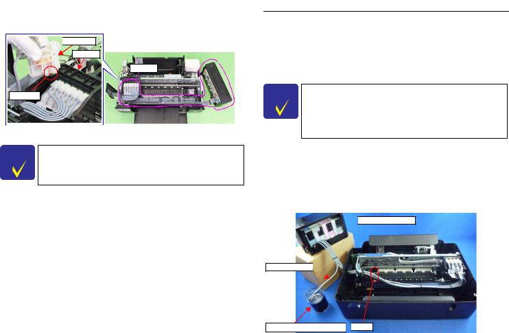
Discharging ink is recommended only when disconnecting the Ink Supply Tank Tube Assy from the Ink Supply Tank. Before performing the above disconnection, discharge ink from the Ink Supply Tank as follows.
̈Necessary tools
•Containers (x 6) for each discharged ink
•Injector (with a tip of φ3.2 mm)
•Tube (capable to be connected to the joint)
C H E C̈ KThe photos in the following procedure are for L200/L201, but P O IN Tthe procedure for L800/L801 is the same; the numbers of the
tube and the location of the Ink Supply Tank Assy in the photos are different from those of L800/L801, though.
̈Prior to the following steps, connect the injector with the tube, and then discharge ink according to the procedure.
C H E CTheKAdapter has an ink valve which cuts off the ink path
P O IN T
when removing the Adapter from the Carriage.
̈Discharging procedure
1.Remove the Housing Upper Assy. (p.25)
2.With the choke value closed (p.11), place the Ink Supply Tank Assy on a place where its bottom is higher than the top of the Printhead.
3.Prepare a container for ink to discharge, then disconnect the Ink Supply Tube from the joint and put its tip into the container for the ink.
4.Open the choke valve to discharge the ink in the Ink Supply Tank Assy to the container.

 Ink Supply Tank Assy
Ink Supply Tube
Container for discharged ink 
 Joint
Joint
Figure 1-5. Discharging Ink (1)
Disassembly/Reassembly |
Overview |
12 |
|
|
CONFIDENTIAL |
Downloaded from www.Manualslib.com manuals search engine
L800/L801 |
Revision A |
|
|
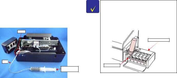
5.When the ink stops flowing from the tube, close the choke valve, and then connect the Ink Supply Tube back to the joint.
6.Disconnect the Ink Supply Tube of the same color connected to the opposite side of the joint.
7.Connect the tube from the injector.
8.Open the choke valve again, and suck up the remaining ink in the Ink Supply Tank into the injector.
9.Disconnect the tube from the injector, and connect the Ink Supply Tube of the same color back to the joint.
Joint
Tube

Injector (tip of φ 3.2 mm)
Figure 1-6. Discharging Ink (2)
10.Repeat Step 3 to Step 10 for all ink tanks to discharge all ink in the Ink Supply Tank.
C H E C̈ KIt is recommended that the ink in the Ink Supply Tank should P O IN Tbe discharged completely before proceeding to disassembling/
reassembling.
̈After all the reassembling work is complete, the discharged ink of each color should be refilled back to the Ink Supply Tank before performing the adjustment. Confirm the colors indicated on the film of the Ink Supply Tank so as not to mistake them, and make sure to refill each ink back to the correct tank from the corresponding ink supply hole.
Ink Supply Tank Assy
Ink supply hole
Disassembly/Reassembly |
Overview |
13 |
|
|
CONFIDENTIAL |
Downloaded from www.Manualslib.com manuals search engine

L800/L801 |
Revision A |
|
|
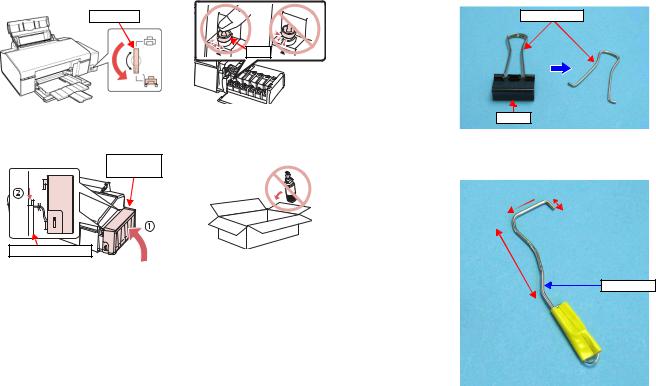
1.1.3 Protection for Transportation
Before packing the printer for returning it to the user, secure it at the specified points with strong tape to avoid damaging the printer or ink leakage during transport, and make sure to check the points as follows.
¸Attaching the Air Release Hole Caps
̈To prevent the ventilation film from getting wet, attach the Air Release Hole Caps (part number: 1556135) to the air release holes of the Ink Supply Tank Assy.
|
|
Air release hole |
|
Ink Supply Tank Assy |
Air Release Hole Cap |
|
|
|
|
|
|
|
|
|
 Air Release Hole Cap
Figure 1-7. Attaching the Air Release Hole Caps
¸ Securing each parts
Secure the following parts with strong tape (width: 22 mm).
̈Securing the CR Unit
1.Confirm that the CR Unit is locked in the home position.
2.Attach the unfolded end of strong tape (fold the other end back 10 mm) on the bottom left of the Adapter Cover.
3.Pull the tape to the right side of the housing and attach it tightly.
CR Unit |
|
Strong tape |
̈Securing the Ink Tank
•Secure both sides of the Top Cover with strong tape (x2).
•Align the unfolded end of strong tape (x5) with the edge of the Housing Upper, and attach the tape along the shape of the Housing Upper/Ink Supply Tank Assy through the openings between the Air Release Hole Caps.
Air Release Hole Cap
Ink Supply
Tank Assy

 Top Cover
Strong tape (80 mm x 22 mm)
Strong tape (60 mm x 22 mm) |
|
Strong tape (60 mm x 22 mm) |

 Fold over the tape edge by 10 mm
Figure 1-9. Securing the Ink Supply Tank Assy
Figure 1-8. Securing the CR Unit
Disassembly/Reassembly |
Overview |
14 |
|
|
CONFIDENTIAL |
Downloaded from www.Manualslib.com manuals search engine
L800/L801 |
Revision A |
|
|
¸ Points to be checked before packing the printer
̈ The Valve Lever is on the position |
̈ All the caps of the Ink Supply Tank |
shown below (the Choke Valve is |
Assy are securely closed. |
closed). (See Figure 1-3.) |
|
Valve Lever |
|
|
Cap |
̈ The hooks (x2) of the Ink Supply |
̈ The opened ink bottle is not |
Tank Assy are securely engaged |
included in the box. |
with the Housing Upper Assy. |
|
Ink Supply |
|
Tank Assy |
|
Housing Upper Assy
1.1.4 Making a Special Tool for Holder Contact
The Holder Contact (refer to p.38) can be easily removed by using a special tool. The method for making the tool is described below.
1.Prepare a handle part of a clip, or a similar metal wire piece.
Handle part
Clip
Figure 1-10. Making Special Tool for Holder Contact (1)
2.Bend the metal wire as shown below.
25mm 
 7mm
7mm
50mm
Special Tool
Figure 1-11. Making Special Tool for Holder Contact (2)
Disassembly/Reassembly |
Overview |
15 |
|
|
CONFIDENTIAL |
Downloaded from www.Manualslib.com manuals search engine
L800/L801 |
Revision A |
|
|
1.1.5 Orientation Definition
Orientation descriptions used in the disassembly/reassembly procedures are as follows.
[Rear Side]
[Left Side] |
|
[Right (home) Side] |
|
|
|
[Front Side]
Figure 1-12. Orientation Definition
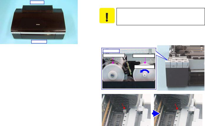
1.1.6 How to Unlock the Carriage
Unlocking the carriage is required for disassembly of some parts or components. Carry out any of the following operations to unlock the carriage and move the carriage to other than its home position.
Be extremely careful not to damage the EJ Roller gear. Extra care
C A U T IO N
must be taken to avoid injury from sharp metal edges.
̈Power the printer and turn it off forcedly by disconnecting the power cable when the CR Unit is unlocked and moved away from the home position.
̈Turn the EJ Roller gear on the left side of the printer in the direction of the arrow until the carriage is unlocked.
[Left side] |
|
PF Roller Gear |
EJ Roller Gear |
|
Turn this gear |
Carriage Lock |
|
|
|
Carriage Lock |
|
|
|
|
|
|
|
|
|
|
|
|
|
|
|
|
|
|
|
|
|
Locked |
|
Unlocked |
Figure 1-13. How to Unlock the Carriage |
|
||
Disassembly/Reassembly |
Overview |
16 |
|
|
CONFIDENTIAL |
Downloaded from www.Manualslib.com manuals search engine

L800/L801 |
Revision A |
|
|
1.2 Disassembly/Reassembly Procedures
1.2.1 Overview
This section describes procedures for disassembling the parts/units in a flowchart format. For some parts/units, detailed procedures or precautions are provided (accordingly indicated by icons and cell's color). Refer to the explanations in the example chart below and perform an appropriate disassembling and reassembling procedure. (See“ 1.3 Removing Exterior Parts/Components (p24)”.)
The example below shows how to see the charts on the following pages.
Table 1-2. Explanatory Note
|
Item |
Description |
Reference |
|
|
|
|
|
|
Parts/unit |
|
White-letter |
Parts/units supplied as an ASP |
--- |
name |
|
Black-letter |
Parts/units not supplied as an ASP |
--- |
|
|
|
|
|
|
|
|
Indicates a practice or condition that could result |
Indicates the reference |
|
|
|
in injury or loss of life if not strictly observed. |
page in blue-letter |
|
|
|
Indicates a practice or condition that could result |
Indicates the reference |
|
|
|
in damage to, or destruction of equipment if not |
page in blue-letter |
|
|
|
strictly observed. |
|
|
|
|
|
|
|
|
|
Indicates the parts that are inevitably broken in |
|
|
|
|
the disassembling procedure, and should be |
--- |
|
|
|
replaced with a new one for reassembly. |
|
|
|
|
Indicates the parts that may cause the ink spill |
“ 1.1.2 Checks and |
|
|
|
Precautions before |
|
|
|
|
when they are removed. |
|
|
|
|
Disassembling (p10)” |
|
|
|
|
|
|
|
|
|
Indicates necessary check items in the |
Indicates the reference |
Icon |
|
|
disassembling/reassembling procedure. |
page in blue-letter |
|
|
|
Indicates supplementary explanation for |
Indicates the reference |
|
|
|
disassembly is given. |
page in blue-letter |
|
|
|
|
|
|
|
|
Indicates particular tasks to keep quality of the |
Indicates the reference |
|
|
|
units are required. |
page in blue-letter |
|
|
|
|
|
|
|
|
Indicates particular adjustment(s) is/are required. |
Chapter 2 “ Adjustment |
|
|
|
|
(p69)” |
|
|
|
Indicates lubrication is required. |
Chapter 3 “ |
|
|
|
Maintenance (p88)” |
|
|
|
|
|
|
|
|
|
Indicates the number of screws securing the |
--- |
|
|
|
parts/units. |
|
|
|
|
|
|
|
|
|
|
|
|
|
|
Indicates the points secured with other than a |
--- |
|
|
|
screw such as a hook, rib, dowel or the like. |
|
|
|
|
|
|
|
|
|
|
|
|
|
|
|
|
|
|
|
Reference page (A) |
|
|
|
|
|
|
|
|
|
|
|
|
|
|
|
|
|
|
|
|
|
Black letters indicate a |
|
|
|
|
|
|
“ 1.5.8 Ink System (p45)” |
|
|
|
|
|
|
||||||
part/unit not supplied as |
|
|
|
Main Board Unit |
|
|
|
|
|
an ASP. |
|
|
|
|
|
|
|
|
|
|
|
|
|
|
|
|
|
|
|
|
|
|
|
|
|
|
|
|
|
Shows the screw types |
|
3 |
|
|
|
|
|
|
|
|
|
and the specified torque |
S7 S15 |
--- |
|
|
|
in the “Screw type/torque |
|
|
|
||
|
|
|
|
|
|
list”. |
|
|
|
|
|
White letters indicate a |
Ink Supply Tank |
|
Front Paper |
|
|
part/unit supplied as an |
Tube Assy |
|
Guide Assy |
|
|
ASP. |
|
--- |
|
|
|
|
|
|
|
2 |
|
|
|
|
|
|
|
|
|
--- |
S9 |
S15 |
1 |
Indicates that the |
|
|
|||
|
|
|
|
|
|
disassembly procedure of |
(P 20) |
|
|
|
|
boxed parts is explained |
|
|
|
|
|
all together and step by |
|
|
|
|
|
step in the section shown |
|
|
|
|
|
as reference page (A). |
|
|
|
|
|
|
Adapter |
|
|
|
|
|
|
--- |
|
|
|
|
|
1 |
|
|
|
|
(p 18) |
|
|
|
|
|
Reference page |
|
|
|
|
Figure 1-14. Example Chart
Disassembly/Reassembly |
Disassembly/Reassembly Procedures |
17 |
|
|
CONFIDENTIAL |
Downloaded from www.Manualslib.com manuals search engine
L800/L801 |
Revision A |
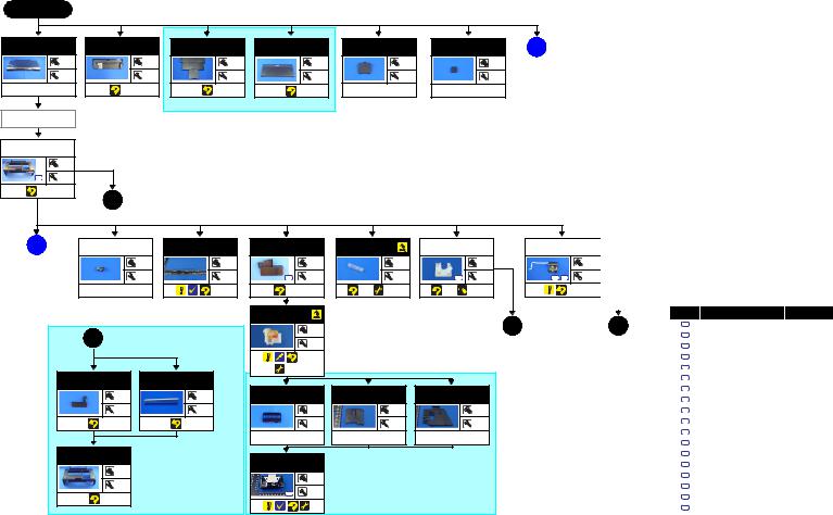
1.2.2 Disassembly Flowchart
START
Printer Cover |
Paper Support |
Stacker Assy |
Stacker Cover |
|
Assy |
||||
|
|
|
||
--- |
--- |
--- |
--- |
|
2 |
2 |
2 |
2 |
|
(p 24) |
(p 24) |
|
|
|
|
|
“ 1.3.3 Stacker Assy / Stacker Cover (p25)” |
||
Paper Support |
|
|
|
|
Assy |
|
|
|
|
Housing Upper |
|
|
Assy |
|
|
|
4 |
|
S4 |
--- |
|
(p 25) |
|
|
|
1 |
(p 18) |
Cover Ink Tube |
Foot |
A |
(p 19) |
--- |
--- |
1 |
--- |
(p 35) |
--- |
B |
(p 20) |
Cover Open |
CR Scale |
Adapter Cover |
Joint |
APG Unit |
Panel Assy |
|
|
Sensor |
|
|
|
|
|
|
|
--- |
--- |
|
1 |
|
--- |
|
2 |
|
|
2 |
|
|
2 |
2 |
S6 |
3 |
|
2 |
S15 |
--- |
S4 |
S14 |
1 |
|
(p 30) |
|
(p 40) |
(p 68) |
|
(p 65) |
(p 69) |
(p 41) |
(p 88) |
|
|
(p 30) |
|
|
|
|
Adapter |
|
|
|
|
|
|
|
|
|
|
“ 1.3.4 Housing Upper Assy (p25)” |
|
--- |
|
|
|
2 |
(p 19) |
|
|
|
|
|
|
|
|
|
|
|
|
|
|||
1 |
(p 18) |
|
1 |
|
|
|
|
|
|
|
||
|
|
|
|
|
|
|
|
|
|
|
|
|
|
|
|
|
(p 68) |
|
|
|
|
|
|
|
|
|
|
|
|
(p 69) |
|
|
|
|
|
|
|
|
Housing Right |
|
Decoration Belt |
|
|
|
|
|
|
|
|
|
|
|
Right |
|
|
|
|
|
|
|
|
|
||
|
|
|
|
|
|
|
|
|
|
|
|
|
|
--- |
|
--- |
Holder Contact |
|
Cover FFC Inner |
Cover FFC |
|
|
|
|
|
|
|
|
|
|
|
|
|
|
|
|
||
|
2 |
|
2 |
|
--- |
|
--- |
|
--- |
|
|
|
|
|
|
|
|
2 |
|
1 |
|
1 |
|
|
|
|
|
|
|
--- |
|
--- |
|
--- |
|
|
|
|
Housing Upper |
|
|
|
|
|
|
|
|
|
|
|
|
|
|
|
|
Printhead |
|
|
|
|
|
|
|
|
|
--- |
|
|
|
|
|
|
|
|
|
|
|
|
|
|
|
|
3 |
|
|
|
|
|
|
|
|
--- |
|
|
|
|
|
|
|
|
|
|
|
|
|
|
|
S2 |
--- |
|
|
|
|
|
|
|
“ 1.5.2 Printhead (p37)”
|
|
|
Screw type/torque list |
|
||
|
|
|
|
|||
|
|
|
|
|||
|
|
|
|
|
|
|
|
|
|
|
Symbol |
Screw type |
Torque |
|
|
|
|
|
|
|
3 |
(p 19) |
|
S1 |
C.B.P. 2.6X8 |
3.5-4.5kgf.cm |
|
|
|
|
|
|
|
|
|
|
|
|
S2 |
C.B.P. 2.6X8 |
3-5kgf.cm |
|
|
|
|
S3 |
C.B.P. 3X10 |
3-5kgf.cm |
|
|
|
|
|
|
|
|
|
|
|
S4 |
C.B.P. 3X10 |
5-7kgf.cm |
|
|
|
|
S5 |
C.B.P. 3X6 |
3-5kgf.cm |
|
|
|
|
|
|
|
|
|
|
|
S6 |
C.B.P. 3X8 |
5-7kgf.cm |
|
|
|
|
S7 |
C.B.P.(P2) 3X8 |
5-7kgf.cm |
|
|
|
|
|
|
|
|
|
|
|
S8 |
C.B.S 3X6 |
5-7kgf.cm |
|
|
|
|
S9 |
C.B.S. (P2) 3X8 |
6-8kgf.cm |
|
|
|
|
|
|
|
|
|
|
|
S10 |
C.B.S. (P4) 3X6 |
7-9kgf.cm |
|
|
|
|
S11 |
C.B.S. (P4) 3X6 |
9-11kgf.cm |
|
|
|
|
|
|
|
|
|
|
|
S12 |
C.B.S. 3X10 |
4-6kgf.cm |
|
|
|
|
S13 |
C.B.S. 3X6 |
4-6kgf.cm |
|
|
|
|
|
|
|
|
|
|
|
S14 |
C.B.S. 3X6 |
5-7kgf.cm |
|
|
|
|
S15 |
C.B.S. 3X6 |
7-9kgf.cm |
|
|
|
|
|
|
|
|
|
|
|
S16 |
C.P. 3X4 |
3-5kgf.cm |
|
|
|
|
S17 |
C.P. 3X6 |
3-5kgf.cm |
|
|
|
|
|
|
|
|
|
|
|
S18 |
C.P. 3X6 |
4-6kgf.cm |
|
|
|
|
|
|
|
Disassembly/Reassembly |
Disassembling/Reassembling Flowchart |
18 |
Confidential
Downloaded from www.Manualslib.com manuals search engine

L800/L801 |
Revision A |
A  (p 18)
Top Cover
--- |
2 |
 (p 61)
Valve Position
Label
--- |
--- |
 (p 61)
Refilling Ink
Label
--- |
--- |
 (p 61)
Tube Valve
Holder Rear
|
3 |
S5 |
6 |
 (p 62)
Bottom Cover
|
8 |
S5 |
--- |


 (p 63)
Valve Lever
--- |
2 |
 (p 62)
Cap |
--- |
--- |
--- |
Top Cover Label
--- |
--- |
 (p 61)
Bottom Cover
Valve Lever |
Left Cover |
Left Cover |
|
--- |
Valve Lever |
Right Cover |
7 |
Right Cover |
|
|
--- |
(p 63) |
|
|
7 |
Cover Joint |
(p 63) |
--- |
|
2 |
|
(p 63) |
Tube Valve
Holder Front
--- |
--- |
 (p 62)
“ 1.5.4 APG Unit (p41)”
2  (p 18)
Spur Gear 12.8 |
Spur Gear 28.8 |
Spur Gear 33.6 |
Combination |
|
Gear 14.22 |
||||
|
|
|
||
--- |
--- |
--- |
--- |
|
--- |
--- |
--- |
--- |
|
--- |
|
--- |
--- |
Compression |
Compression |
Combination |
Spring 2.25 |
Spring 0.97 |
Gear 12.8.27 |
--- |
--- |
--- |
--- |
--- |
--- |
--- |
--- |
--- |
APG Holder |
--- |
--- |
--- |
3 (p 18) |
“ 1.4.2 Panel Assy/ Cover Open Sensor (p30)” |
|
Panel Cover
Assy
|
2 |
S3 |
--- |
---
Panel Unit |
--- |
--- |
--- |
Panel Cover
--- |
--- |
--- |
Open Sensor
Holder
|
1 |
S3 |
4 |
---
Panel Shield |
|
Plate |
|
|
2 |
S3 |
--- |
Panel Board |
Housing Panel |
|
Assy |
||
|
||
--- |
--- |
|
1 |
--- |
|
--- |
--- |
Decoration Belt |
Left |
--- |
--- |
--- |
Screw type/torque list
Symbol |
Screw type |
Torque |
|
|
|
S1 |
C.B.P. 2.6X8 |
3.5-4.5kgf.cm |
|
|
|
S2 |
C.B.P. 2.6X8 |
3-5kgf.cm |
S3 |
C.B.P. 3X10 |
3-5kgf.cm |
|
|
|
S4 |
C.B.P. 3X10 |
5-7kgf.cm |
S5 |
C.B.P. 3X6 |
3-5kgf.cm |
|
|
|
S6 |
C.B.P. 3X8 |
5-7kgf.cm |
S7 |
C.B.P.(P2) 3X8 |
5-7kgf.cm |
|
|
|
S8 |
C.B.S 3X6 |
5-7kgf.cm |
S9 |
C.B.S. (P2) 3X8 |
6-8kgf.cm |
|
|
|
S10 |
C.B.S. (P4) 3X6 |
7-9kgf.cm |
S11 |
C.B.S. (P4) 3X6 |
9-11kgf.cm |
|
|
|
S12 |
C.B.S. 3X10 |
4-6kgf.cm |
S13 |
C.B.S. 3X6 |
4-6kgf.cm |
|
|
|
S14 |
C.B.S. 3X6 |
5-7kgf.cm |
S15 |
C.B.S. 3X6 |
7-9kgf.cm |
|
|
|
S16 |
C.P. 3X4 |
3-5kgf.cm |
S17 |
C.P. 3X6 |
3-5kgf.cm |
|
|
|
S18 |
C.P. 3X6 |
4-6kgf.cm |
|
|
|
Disassembly/Reassembly |
Disassembling/Reassembling Flowchart |
19 |
Confidential
Downloaded from www.Manualslib.com manuals search engine
L800/L801 |
Revision A |
B(p 18)
Main Board Unit |
“ 1.4.1 Main Board Unit (p27)” |
Tube Holder* |
*: There are four Tube Holders installed in this printer. Depending on the target parts or units, the number of |
|
|||
|
|
|
|
|
|
|
|
|
|
Tube Holders you should remove differs. |
|
|||
|
|
3 |
|
|
|
|
1 |
̈ When removing the Ink Supply Tank Assy: |
The Tube Holder on the home position side (on the Cover Case) |
|||
|
|
|
|
|
|
|
|
|||||
S7 |
S15 |
--- |
|
|
|
S6 |
1 |
̈ When removing the Printer Mechanism: |
All Tube Holders |
|||
|
|
Upper Shield |
|
|
|
--- |
|
|
|
|
|
|
|
|
|
|
|
|
|
|
|
|
|
|
|
|
|
Plate M/B |
|
|
|
|
|
|
|
|
|
|
|
|
|
7 |
|
|
|
|
|
|
|
|
|
|
|
|
--- |
|
|
Ink Supply Tank |
|
|
Adapter Cover |
Adapter Cover |
||
|
|
S14 S18 |
|
|
Assy |
|
|
|
||||
|
|
|
|
|
|
|
|
|
|
|||
|
|
|
|
|
|
|
--- |
|
|
Adapter |
|
|
|
|
|
|
|
|
|
--- |
|
|
|
|
Tube Guide |
|
|
|
|
|
|
|
|
|
Joint |
|
Sheet |
|
|
|
|
|
|
|
|
|
|
|
|
||
|
|
Shield Plate M/B |
|
Lower Shield |
|
(p 64) |
(p 69) |
Ink Supply Tank |
|
|
--- |
|
|
|
Sub |
|
Plate M/B |
|
|
|
|
|
|||
|
|
|
|
|
|
|
|
Tube Assy |
|
|
|
|
|
|
|
2 |
|
2 |
|
|
|
|
Ink Supply Tube |
3 |
|
|
|
|
|
|
|
|
|
|
--- |
Assy (W/Clamp) |
|
|
|
|
S13 |
--- |
S13 |
--- |
|
|
|
|
|
|
(p 66) |
|
|
|
|
|
|
|
|
|
--- |
|
--- |
Tube Guide |
|
|
|
|
|
|
|
|
|
|
Sheet Sub |
||
|
|
|
|
|
|
|
|
|
|
|
|
|
|
|
|
|
|
|
|
|
(p 64) |
(p 69) |
|
--- |
--- |
|
|
|
|
|
|
|
|
|
|
|
|
|
|
|
|
|
|
|
|
|
|
|
|
|
Tube Guide |
|
|
|
|
|
|
|
|
|
|
(p 67) |
(p 69) |
1 |
|
|
|
|
|
|
|
|
|
|
|
|
|
|
|
Main Board |
|
|
|
|
|
Top Cover |
|
|
--- |
|
|
|
|
|
|
|
|
|
|
|
|||
|
|
|
|
|
|
|
|
|
|
(p 66) |
||
|
|
|
|
|
|
|
|
|
|
|
|
|
|
|
|
1 |
|
|
|
|
|
|
|
|
4 |
|
|
|
|
|
|
|
Bottom Cover |
|
|
|
||
|
|
|
|
|
|
|
|
|
|
|
||
|
|
|
--- |
|
|
|
|
|
|
|
|
--- |
|
|
S12 |
|
|
|
|
|
|
|
|
|
|
|
|
|
|
|
|
|
|
Valve Lever |
|
|
|
|
|
|
|
|
|
|
|
|
Right Cover |
|
|
|
|
Screw type/torque list
Left Cover
Symbol |
Screw type |
Torque |
|
|
APG Sensor |
|
|
|
Cover Joint |
S1 |
C.B.P. 2.6X8 |
3.5-4.5kgf.cm |
|
Cover Ink Tube |
PF Encoder |
PF Scale |
|
|
|
|||||
Assy |
|
|
|
|
|
|||||
|
|
|
|
|
Tube Valve |
S2 |
C.B.P. 2.6X8 |
3-5kgf.cm |
||
|
|
|
|
|
|
|
|
|
||
Panel Assy |
--- |
|
1 |
--- |
Holder Rear |
S3 |
C.B.P. 3X10 |
3-5kgf.cm |
||
|
|
|
||||||||
|
|
2 |
|
--- |
--- |
Tube Valve |
S4 |
C.B.P. 3X10 |
5-7kgf.cm |
|
Tube Holder |
S1 |
Holder Front |
|
|
|
|||||
|
|
|
|
|
|
S5 |
C.B.P. 3X6 |
3-5kgf.cm |
||
|
|
|
|
|
|
|
|
|||
Ink Supply Tank |
--- |
|
|
|
|
|
|
C.B.P. 3X8 |
5-7kgf.cm |
|
|
|
|
|
|
|
S6 |
||||
Assy |
|
|
|
“ 1.5.10 PF Encoder / PF Scale (p49)” |
Ink Supply Tank |
|
C.B.P.(P2) 3X8 |
5-7kgf.cm |
||
|
|
|
|
S7 |
||||||
Adapter Cover |
Photo Interrupter |
|
|
|
|
|
S8 |
C.B.S 3X6 |
5-7kgf.cm |
|
|
|
|
|
|
|
|
--- |
|||
|
|
|
|
|
|
|
|
C.B.S. (P2) 3X8 |
6-8kgf.cm |
|
|
|
|
|
|
|
|
|
S9 |
||
Adapter |
|
--- |
|
|
|
|
|
--- |
C.B.S. (P4) 3X6 |
7-9kgf.cm |
|
|
|
|
|
|
|
|
S10 |
||
Tube Guide |
2 |
|
|
|
(p 64) |
(p 69) |
S11 |
C.B.S. (P4) 3X6 |
9-11kgf.cm |
|
Sheet/Tube |
|
|
|
|||||||
|
|
|
|
|
|
|
|
|
||
Guide Sheet Sub |
--- |
|
|
|
|
|
S12 |
C.B.S. 3X10 |
4-6kgf.cm |
|
|
|
|
|
|
|
|
|
|
|
|
|
|
|
|
|
|
|
|
S13 |
C.B.S. 3X6 |
4-6kgf.cm |
|
|
“ 1.5.16 APG Sensor Assy |
|
|
|
|
|
S14 |
C.B.S. 3X6 |
5-7kgf.cm |
|
|
(p57)” |
|
|
|
|
|
|||
C |
(p 21) |
|
|
|
|
|
|
C.B.S. 3X6 |
7-9kgf.cm |
|
|
|
|
|
|
|
S15 |
||||
|
|
|
|
|
|
|
|
S16 |
C.P. 3X4 |
3-5kgf.cm |
|
|
|
|
|
|
|
|
S17 |
C.P. 3X6 |
3-5kgf.cm |
|
|
|
|
|
|
|
|
S18 |
C.P. 3X6 |
4-6kgf.cm |
Disassembly/Reassembly |
Disassembling/Reassembling Flowchart |
20 |
Confidential
Downloaded from www.Manualslib.com manuals search engine

L800/L801 |
Revision A |
C (p 20) |
4 (p 21) |
|
|
|
|
“ 1.5.12 CR Motor (p50)” |
|
|
|
|
Cover Case |
|
Extension Spring |
|
PF Encoder/ |
Porous Pad |
D |
(p 22) |
|
|
|
|
|
PF Scale |
|
Paper Guide |
||
|
1 |
|
--- |
|
|
Front |
|
|
|
|
|
|
|
|
|
||
|
--- |
|
2 |
|
|
|
--- |
|
S6 |
|
|
|
|
|
|
||
|
|
|
|
PF Motor |
|
|
--- |
|
|
|
|
|
|
|
|
|
|
(p 65) |
|
--- |
|
|
|
|
|
|
|
|
|
|
|
2 |
(p 57) |
|
|
Printer |
|
Driven Pulley |
|
S17 |
--- |
|
|
|
|
|
|
|
|
|
|
||
Mechanism |
|
Assy |
|
(p 49) |
(p 69) |
|
|
|
|
|
|
|
|
|
|
||
|
5 |
(p 21) |
--- |
|
|
|
|
|
|
4 |
|
|
|
|
|
|
|
S6 |
4 |
|
--- |
Driven Pulley |
|
|
|
|
|
|
|
Driven Pulley |
Shaft |
|
|
|
|
|
|
|
|
|
|
|
|
|
(p 35) |
(p 69) |
|
--- |
--- |
|
|
|
|
|
|
|
|
|
|
|
||
|
|
|
--- |
--- |
|
|
|
|
|
|
CR Motor |
|
|
|
|
|
|
|
|
|
2 |
|
|
|
|
|
|
|
S16 |
--- |
|
|
|
|
|
|
|
|
Driven Pulley |
|
|
|
|
|
|
|
|
Holder |
|
|
|
|
|
|
|
|
--- |
|
|
|
|
|
Housing Lower |
|
--- |
|
|
|
|
|
|
|
|
|
|
|
|
|
||
Assy |
|
|
|
|
|
|
|
|
---
---
|
|
|
“ 1.5.7 Left & Right Guide |
Waste Ink Pad |
Waste Ink Pad |
|
|
|
|
|
--- |
Stacker Assy |
|
Stackers / CDR Guide Sensor |
P/S Assy |
|
Waste Ink Tray |
||||
|
Lower |
Cap Lower |
|
|||||||
|
|
|
(p44)” |
|
|
|
|
|
||
|
|
|
|
|
|
|
|
|
|
|
|
Stacker Cover |
|
|
|
--- |
--- |
|
1 |
|
2 |
Waste Ink Pad |
|
|
|
|
|
|
|
|
|
|
Lower |
|
|
|
|
--- |
--- |
S4 |
--- |
S4 |
1 |
Waste Ink Pad |
|
|
|
|
|
|
(p 34) |
(p 69) |
(p 42) |
(p 69) |
Cap |
|
|
|
|
|
|
||||
Guide Stacker |
|
Guide Stacker |
|
|
|
|
|
|
|
|
|
|
|
“ 1.5.6 Waste Ink Pad Lower / Waste Ink Pad Cap Lower (p43)” |
|
|
|
|
|||
P/S Assy |
Left |
|
Right Assy |
|
|
|
|
|
||
|
|
|
|
|
|
|
|
|
|
|
|
|
1 |
|
1 |
|
|
|
|
|
|
|
S6 |
--- |
S6 |
--- |
CDR Guide |
|
|
|
|
|
|
|
|
|
|
Label CDR |
|
|
|
|
|
|
|
|
|
|
Sensor |
|
|
|
|
|
|
|
|
|
|
|
|
|
|
|
|
|
|
|
|
|
--- |
--- |
|
|
|
|
|
|
|
|
|
2 |
--- |
|
|
|
|
Housing Lower |
|
|
|
|
--- |
--- |
|
|
|
|
(W/Foot) |
|
|
|
|
|
|
|
|
|
|
--- |
Guide Stacker |
|
|
--- |
Right |
|
|
|
--- |
--- |
|
|
--- |
|
--- |
Screw type/torque list
Symbol |
Screw type |
Torque |
|
|
|
S1 |
C.B.P. 2.6X8 |
3.5-4.5kgf.cm |
|
|
|
S2 |
C.B.P. 2.6X8 |
3-5kgf.cm |
S3 |
C.B.P. 3X10 |
3-5kgf.cm |
|
|
|
S4 |
C.B.P. 3X10 |
5-7kgf.cm |
S5 |
C.B.P. 3X6 |
3-5kgf.cm |
|
|
|
S6 |
C.B.P. 3X8 |
5-7kgf.cm |
S7 |
C.B.P.(P2) 3X8 |
5-7kgf.cm |
|
|
|
S8 |
C.B.S 3X6 |
5-7kgf.cm |
S9 |
C.B.S. (P2) 3X8 |
6-8kgf.cm |
|
|
|
S10 |
C.B.S. (P4) 3X6 |
7-9kgf.cm |
S11 |
C.B.S. (P4) 3X6 |
9-11kgf.cm |
|
|
|
S12 |
C.B.S. 3X10 |
4-6kgf.cm |
S13 |
C.B.S. 3X6 |
4-6kgf.cm |
|
|
|
S14 |
C.B.S. 3X6 |
5-7kgf.cm |
S15 |
C.B.S. 3X6 |
7-9kgf.cm |
|
|
|
S16 |
C.P. 3X4 |
3-5kgf.cm |
S17 |
C.P. 3X6 |
3-5kgf.cm |
|
|
|
S18 |
C.P. 3X6 |
4-6kgf.cm |
|
|
|
Disassembly/Reassembly |
Disassembling/Reassembling Flowchart |
21 |
Confidential
Downloaded from www.Manualslib.com manuals search engine
L800/L801 |
Revision A |
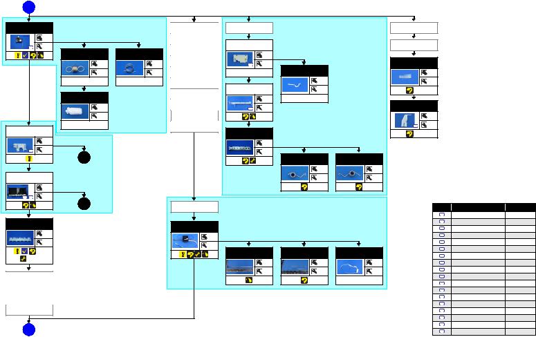
D  (p 21)
|
“ 1.5.8 Ink System (p45)” |
|
“ 1.5.9 EJ Frame Assy (p46)” |
|
|
|
|
Ink System |
APG Unit |
Tube Guide |
Tube Guide |
|
|
2 |
|
|
Extension Spring |
|
|
|
|
|
|
|
|
|
|
|
|
|
Cable Holder |
|
|
Cable Holder |
|
|
|
|
S15 |
--- |
|
|
Driven Pulley |
Frame |
|
|
Frame |
|
|
|
|
|
ExtensionSpring |
Compression |
Assy |
|
2 |
|
|
|
|
|
|
|
|
0.8 |
|
Spring 0.98 |
|
|
|
|
|
|
|
|
|
|
|
|
|
CR Scale |
|
|
|
PF Scale Sheet |
|
|
|
|
|
|
--- |
--- |
|
S15 |
2 |
|
|
|
|
|
|
|
|
|
|
|
|
|
|
||||
|
|
|
2 |
--- |
Adapter Cover |
--- |
|
PF Encoder FFC |
|
--- |
|
|
|
|
|
|
|
|
|
|
|||||
|
|
|
|
|
|
|
|
|
||||
|
|
--- |
|
--- |
Adapter |
|
|
--- |
|
--- |
|
|
|
|
|
|
|
|
Front Frame |
|
--- |
(p 66) |
|
|
|
|
|
|
|
|
Cover FFC |
|
|
|
|
|
|
|
|
|
CR Lock |
|
|
|
|
2 |
--- |
|
|
|
|
|
|
|
|
|
|
|
|
|
|
|
||
|
|
|
--- |
|
Cover FFC Inner |
|
--- |
|
PF Scale Cover |
|
|
|
|
|
|
|
|
|
|
|
|
|
|||
|
|
|
|
|
S15 |
|
|
|
|
|
||
|
|
|
--- |
|
Holder Contact |
|
|
|
|
1 |
|
|
|
|
--- |
|
|
Printhead |
|
|
|
S6 |
1 |
|
|
LD Roller |
|
|
|
|
|
|
|
|
|
|
|
|
Guide Assy |
|
|
|
EJ Frame Assy |
|
|
(p 66) |
|
|
|
||
|
|
“ 1.5.14 ASF Unit (p54)” |
|
|
|
|
|
|
|
|
|
|
|
|
1 |
|
|
|
|
--- |
|
|
|
|
|
|
|
|
|
|
|
|
|
|
|
|
|
|
|
S10 |
5 |
|
|
|
|
--- |
|
|
|
|
|
|
|
|
|
|
|
|
|
|
|
|
|
|
|
|
5 |
(p 23) |
|
|
|
|
EJ Frame |
EJ Frame |
|
|
|
|
|
|
|
|
|
|
|
Torsion Spring L |
Torsion Spring R |
|
|
|
|
|
|
|
|
|
|
|
--- |
--- |
|
|
|
ASF Unit |
|
|
|
|
|
|
--- |
--- |
|
|
|
|
|
|
2 |
|
|
|
|
|
|
|
|
|
|
S10 |
S11 |
2 |
|
|
|
|
|
|
|
Screw type/torque list |
|
|
|
|
6 |
(p 23) |
|
Cable Holder |
|
|
|
“ 1.5.13 CR Unit (p52)” |
Symbol |
Screw type |
Torque |
|
|
|
|
|
Frame |
|
|
|
|
|||
|
|
|
|
|
|
|
|
|
|
|
|
|
|
|
|
|
|
|
|
|
|
|
S1 |
C.B.P. 2.6X8 |
3.5-4.5kgf.cm |
Upper Paper |
|
|
|
|
|
|
|
S2 |
C.B.P. 2.6X8 |
3-5kgf.cm |
||
Guide |
|
|
|
CR Unit |
|
|
|
|
|
C.B.P. 3X10 |
3-5kgf.cm |
|
|
|
|
|
|
|
|
|
|
S3 |
|||
|
|
|
|
|
|
|
|
|
|
|
||
|
|
--- |
|
|
|
--- |
|
|
|
S4 |
C.B.P. 3X10 |
5-7kgf.cm |
|
|
|
|
|
|
|
|
|
|
|
|
|
|
|
--- |
|
|
|
|
|
|
|
S5 |
C.B.P. 3X6 |
3-5kgf.cm |
|
|
|
|
|
|
2 |
|
|
|
|
C.B.P. 3X8 |
5-7kgf.cm |
|
|
|
|
|
|
|
|
|
|
S6 |
||
|
(p 56) |
|
|
|
CR Guide Shaft |
|
Timing Belt |
Head FFC |
|
C.B.P.(P2) 3X8 |
5-7kgf.cm |
|
|
|
|
|
|
|
|
|
|
|
S7 |
||
|
(p 69) |
|
|
|
|
|
--- |
--- |
--- |
|
C.B.S 3X6 |
5-7kgf.cm |
|
|
|
|
|
|
|
S8 |
|||||
|
|
|
|
|
|
|
--- |
--- |
--- |
S9 |
C.B.S. (P2) 3X8 |
6-8kgf.cm |
|
|
|
|
|
|
|
|
|
|
|||
Tube Guide |
|
|
|
|
|
|
|
S10 |
C.B.S. (P4) 3X6 |
7-9kgf.cm |
||
|
|
|
|
|
|
|
|
|
--- |
S11 |
C.B.S. (P4) 3X6 |
9-11kgf.cm |
Cable Holder |
|
|
|
|
|
|
|
|||||
|
|
|
|
|
|
|
|
|
|
|||
Frame |
|
|
|
|
|
|
|
|
S12 |
C.B.S. 3X10 |
4-6kgf.cm |
|
Front Frame |
|
|
|
|
|
|
|
S13 |
C.B.S. 3X6 |
4-6kgf.cm |
||
|
|
|
|
|
|
|
|
|
|
|||
|
|
|
|
|
|
|
|
|
|
S14 |
C.B.S. 3X6 |
5-7kgf.cm |
EJ Frame Assy |
|
|
|
|
|
|
|
S15 |
C.B.S. 3X6 |
7-9kgf.cm |
||
|
|
|
|
|
|
|
|
|
|
|
||
|
|
|
|
|
|
|
|
|
|
S16 |
C.P. 3X4 |
3-5kgf.cm |
|
|
|
|
|
|
|
|
|
|
S17 |
C.P. 3X6 |
3-5kgf.cm |
|
E |
(p 23) |
|
|
|
|
|
|
|
S18 |
C.P. 3X6 |
4-6kgf.cm |
Disassembly/Reassembly |
Disassembling/Reassembling Flowchart |
22 |
Confidential
Downloaded from www.Manualslib.com manuals search engine

L800/L801 |
Revision A |
E  (p 22)
EJ Ground
Spring
--- |
3 |
Front Paper
Guide Assy
|
|
2 |
S9 |
S15 |
1 |
CDR Tray
Sensor
--- |
2 |
 (p 60)
|
|
“ 1.5.17 Front Paper Guide Assy (p57)” |
||
PE Lever/ |
Spur Gear 26.5 |
Porous Pad |
Photo Interrupter |
|
PE Lever |
Paper Guide |
(PE Sensor) |
||
|
||||
Torsion Spring |
|
Front |
|
|
|
--- |
|
--- |
|
|
--- |
|
|
|
|
1 |
|
4 |
|
|
2 |
|
|
|
--- |
--- |
|
--- |
|
|
|
|
||
6 (p 22) |
“ 1.5.14 ASF Unit (p54)” |
|||
|
||||
|
|
|
|
|
|
|
|
|
|
Retard Roller |
Combination |
|
Holder Assy |
Gear 168.32.8 |
|
|
--- |
--- |
|
2 |
1 |
--- |
|
--- |
5 |
(p 22) |
|
Torsion Spring
137.7
--- |
--- |
---
LD Roller Guide
--- |
--- |
--- |
Spur Gear 16 |
LD Roller |
|
Shaft Assy |
||
|
||
|
|
--- |
--- |
--- |
2 |
--- |
|
Change Lever |
|
Assy |
|
--- |
|
--- |
Compression |
|
Spring 2.36 |
--- |
--- |
|
|
|
--- |
ASF Assy |
--- |
|
|
--- |
|
--- |
Change Lever |
--- |
--- |
|
|
|
1 |
|
--- |
LD Roller |
--- |
--- |
--- |
|
Screw type/torque list |
|
|
||
|
|
|
|
|
|
|
|
Symbol |
Screw type |
Torque |
|
|
|
|
|
|
|
|
|
S1 |
C.B.P. 2.6X8 |
3.5-4.5kgf.cm |
|
|
|
|
|
|
|
|
|
S2 |
C.B.P. 2.6X8 |
3-5kgf.cm |
|
|
|
S3 |
C.B.P. 3X10 |
3-5kgf.cm |
|
|
|
|
|
|
|
|
|
S4 |
C.B.P. 3X10 |
5-7kgf.cm |
|
|
|
S5 |
C.B.P. 3X6 |
3-5kgf.cm |
|
|
|
|
|
|
|
|
|
S6 |
C.B.P. 3X8 |
5-7kgf.cm |
|
|
|
S7 |
C.B.P.(P2) 3X8 |
5-7kgf.cm |
|
|
|
|
|
|
|
|
|
S8 |
C.B.S 3X6 |
5-7kgf.cm |
|
|
|
S9 |
C.B.S. (P2) 3X8 |
6-8kgf.cm |
|
|
|
|
|
|
|
|
|
S10 |
C.B.S. (P4) 3X6 |
7-9kgf.cm |
|
|
|
S11 |
C.B.S. (P4) 3X6 |
9-11kgf.cm |
|
|
|
|
|
|
|
|
|
S12 |
C.B.S. 3X10 |
4-6kgf.cm |
|
|
|
S13 |
C.B.S. 3X6 |
4-6kgf.cm |
|
|
|
|
|
|
|
|
|
S14 |
C.B.S. 3X6 |
5-7kgf.cm |
|
|
|
S15 |
C.B.S. 3X6 |
7-9kgf.cm |
|
|
|
|
|
|
|
|
|
S16 |
C.P. 3X4 |
3-5kgf.cm |
|
|
|
S17 |
C.P. 3X6 |
3-5kgf.cm |
|
|
|
|
|
|
|
|
|
S18 |
C.P. 3X6 |
4-6kgf.cm |
|
|
|
|
|
|
|
Disassembly/Reassembly |
Disassembling/Reassembling Flowchart |
|
23 |
||
Confidential
Downloaded from www.Manualslib.com manuals search engine

L800/L801 Revision A
1.3 Removing Exterior Parts/Components |
1.3.2 Paper Support Assy |
|
¸ Removal procedure |
|
1.3.1 Printer Cover
¸Removal procedure
1.Pull out the left shaft and right shaft of the Printer Cover, and remove the Printer Cover.
1.Open the Paper Support Assy.
2.Disengage the right shaft of the Paper Support Assy from the bushing of the ASF Unit by pushing the bushing outward. Then remove the Paper Support Assy, disengaging the left shaft preventing the Edge Guide projection from hitting against the other parts.
Printer Cover |
|
Shaft (left) |
Shaft (right) |
Figure 1-15. Removing the Printer Cover
Paper Support Assy |
|
Edge Guide |
||
|
|
|
|
Projection |
|
|
|
|
|
|
|
|
|
|
Push |
:Shaft
 Bushing of the ASF
Figure 1-16. Removing the Paper Support Assy
When reinstalling the Paper Support Assy, match the projection and hole of the Edge Guide, then attach the right shaft and the left shaft in that order. (Put the shafts at the front side in the bushing and then push them rearward.) After reinstalling, check that the Paper Support Assy moves smoothly.
Paper Support Assy
Convex Portion
2 |
1 |
Mounting Direction |
Hole |
|
(from front side to rear side) |
: Shaft |
Figure 1-17. Reinstalling the Paper Support Assy
Disassembly/Reassembly |
Printer Cover |
24 |
|
|
CONFIDENTIAL |
Downloaded from www.Manualslib.com manuals search engine

L800/L801 |
Revision A |
|
|
1.3.3 Stacker Assy / Stacker Cover
¸Removal procedure
1.Open the Stacker Cover.
2.Remove the Stacker Assy.
3.Release the Stacker Cover from the two shafts and remove the Stacker Cover.
|
|
Shaft |
Shaft |
|
|
|
|
|
Stacker Assy |
|
Stacker Cover |
|
|
|
Figure 1-18. Removing the Stacker Assy / Stacker Cover
When installing the Stacker Assy, insert the guide pins of the Stacker Assy into the lower grooves of the Guide Stacker Assy. (The upper grooves are used when CDR is printed.)
Groove |
Guide Pin |
Groove |
Guide Pin |
Figure 1-19. Installing the Stacker Assy
1.3.4 Housing Upper Assy
¸Removal procedure
1.Remove the four screws and remove the Upper Housing upward.
•Screw  C.B.P. M3x10 (tightening torque: 5-7 kgf.cm)
(The numbers shown in the figure indicate the order of tightening the screws.)
[Rear Side]
4 |
3 |
1 |
2 |
Upper Housing
Groove |
Groove |
Figure 1-20. Removing the Upper Housing
Disassembly/Reassembly |
Stacker Assy / Stacker Cover |
25 |
|
|
CONFIDENTIAL |
Downloaded from www.Manualslib.com manuals search engine
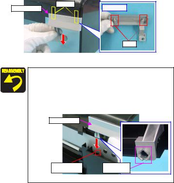
L800/L801 |
Revision A |
|
|
2.Slide the Front Housing in the direction of the arrow and remove the Front Housing from the Upper Housing.
|
Grooves |
Front Housing |
[Rear Side] |
|
|
|
Ribs |
Figure 1-21. Removing the Front Housing
When installing the Upper Housing, be careful of the following:
̈Do not pinch the cables.
̈Tighten the screws in the order given in Fig.1-20 (p.25).
̈Match the ribs of the Upper Housing shown in Fig.1-20 (p.25) with the grooves of the Housing Lower.
̈As shown in Fig.1-22, match the A part of the Front Housing with the screw box of the Housing Lower.
Front Housing
Screw box of Housing Lower
A part of Front Housing
Figure 1-22. Installing Upper Housing
Disassembly/Reassembly |
Housing Upper Assy |
26 |
|
|
CONFIDENTIAL |
Downloaded from www.Manualslib.com manuals search engine
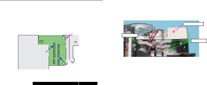
L800/L801 |
Revision A |
|
|
1.4 Removing Control Boards
1.4.1 Main Board Unit
¸ Removal procedure
̈Main Board Unit removal
1.Disconnect all connectors on the Main Board Unit.
2.Peel off the double-sided tape that secures the Panel FFC to the Holder Frame and release the Panel FFC. (Fig.1-29 (p.30))
|
|
|
|
CN3 |
CN17 |
|
CN6 |
CN7 |
|
|
|
|
|
Main Board Unit |
|
|||||||
|
|
|
|
|
|
|
|
|
|
|
|
|
|
|
|
|
|
|
|
|
|
|
|
|
|
|
|
|
|
|
|
|
|
|
|
|
|
|
|
|
|
|
|
|
|
|
|
|
|
|
|
|
|
|
|
|
|
|
|
|
|
|
|
|
|
|
|
|
|
|
|
|
|
|
|
|
|
|
|
|
|
|
|
CN4 |
|
|
|
|
|
|
|
|
|
|
|
|
CN13 |
CN14 |
|
|
|
|
|
|
|
|
|
|
|
|
|
|||
|
|
|
|
|
|
|
|
|
|
|
|
|
|
|
CN16 |
|
|
|
|
|
||
|
|
|
|
|
|
|
|
|
|
|
|
|
|
|
|
|
|
|||||
|
|
|
|
|
|
CN12 |
|
|
|
|
|
|
|
|
|
|
|
|
|
|||
|
|
|
|
|
|
|
|
|
|
|
|
|
|
|
|
|
|
|
|
|
|
|
|
|
|
|
|
|
CN11 |
|
|
|
|
|
|
|
|
|
|
|
|
|
|||
|
|
|
|
|
|
|
|
|
|
|
|
|
|
|
|
|
|
|
|
|
|
|
|
|
|
|
|
|
|
|
|
|
|
|
|
|
|
|
CN10 |
|
|
|
|
||
|
|
|
|
|
|
|
|
|
|
|
|
|
|
|
|
|
|
|
|
|
|
|
|
|
|
|
|
|
|
|
|
|
|
|
|
|
|
|
|
|
|
||||
|
|
|
|
|
|
|
|
|
|
CN8 |
|
CN5 |
|
|
|
|
|
|
|
|||
|
Figure 1-23. Connector layout of the Main Board |
|||||||||||||||||||||
|
Table 1-3. List of Connectors and their Destinations |
|||||||||||||||||||||
|
|
|
|
|
|
|
|
|
|
|
|
|
|
|
|
|
|
|
|
|
|
|
CN No.@ |
|
Color |
|
|
|
|
|
|
|
Destination |
|
|
Number of pins |
|||||||||
CN3 |
|
White |
P/S Assy |
|
|
|
|
|
|
|
|
|
3pin |
|||||||||
|
|
|
|
|
|
|
|
|
|
|
|
|
|
|
|
|
|
|
|
|
|
|
CN4 |
|
White |
CDR Guide Sensor / CDR Tray Sensor |
|
|
4pin |
||||||||||||||||
CN5 |
|
FFC |
Panel Board |
|
|
|
|
|
|
|
|
|
8pin |
|||||||||
|
|
|
|
|
|
|
|
|
|
|
|
|
|
|
|
|
|
|
|
|
|
|
CN6 |
|
White |
PE Sensor |
|
|
|
|
|
|
|
|
|
3pin |
|||||||||
|
|
|
|
|
|
|
|
|
|
|
|
|
|
|
|
|
|
|
|
|
|
|
CN7 |
|
Black |
APG Sensor |
|
|
|
|
|
|
|
|
|
3pin |
|||||||||
|
|
|
|
|
|
|
|
|
|
|
|
|
|
|
|
|
|
|
|
|
|
|
CN8 |
|
FFC |
PF Encoder |
|
|
|
|
|
|
|
|
|
5pin |
|||||||||
|
|
|
|
|
|
|
|
|
|
|
|
|
|
|
|
|
|
|
|
|
|
|
CN10 |
|
FFC |
|
|
|
|
|
|
|
|
|
|
|
|
|
|
|
|
|
|
13pin |
|
|
|
|
Head FFC |
|
|
|
|
|
|
|
|
|
|
|
||||||||
CN11 |
|
FFC |
|
|
|
|
|
|
|
|
|
13pin |
||||||||||
CN12 |
|
FFC |
|
|
|
|
|
|
|
|
|
|
|
|
|
|
|
|
|
|
9pin |
|
CN13 |
|
Black |
PF Motor |
|
|
|
|
|
|
|
|
|
2pin |
|||||||||
|
|
|
|
|
|
|
|
|
|
|
|
|
|
|
|
|
|
|
|
|
|
|
CN14 |
|
White |
CR Motor |
|
|
|
|
|
|
|
|
|
2pin |
|||||||||
|
|
|
|
|
|
|
|
|
|
|
|
|
|
|
|
|
|
|
|
|
|
|
CN16 |
|
FFC |
PW Sensor / CR Encoder Sensor |
|
|
6pin |
||||||||||||||||
|
|
|
|
|
|
|
|
|
|
|
|
|
|
|
|
|
|
|
|
|
|
|
CN17 |
|
White |
Cover Open Sensor |
|
|
|
|
|
|
|
|
|
2pin |
|||||||||
3.Peel off the four acetate tapes that secures the following cables on the back of the Main Board Unit.
•Power Supply Cable
•CR Motor Cable
•PF Motor Cable
•PE Motor Cable
•APG Sensor Cable
 Main Board Unit
Acetate Tape
Acetate Tape
Figure 1-24. Removing the Main Board Unit (1)
Disassembly/Reassembly |
Main Board Unit |
27 |
|
|
CONFIDENTIAL |
Downloaded from www.Manualslib.com manuals search engine
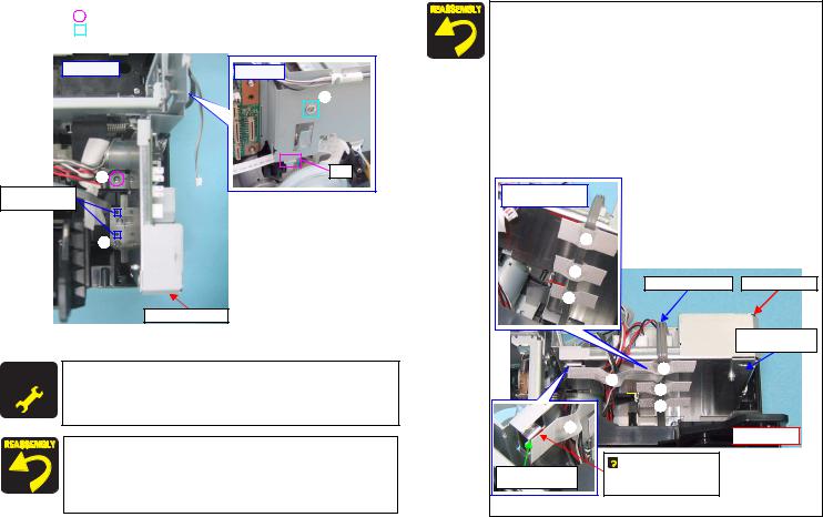
L800/L801 |
Revision A |
|
|
4.Remove the three screws and remove the Main Board Unit.
• Screw |
(2 pcs.): C.B.P.(P2) M3x8 (tightening torque: 5-7 kgf.cm) |
• Screw |
(1 pc.): C.B.S. M3x6 (tightening torque: 7-9 kgf.cm) |
(The numbers shown in the figure indicate the order of tightening the screws.)
[Upper Side] |
[Left Side] |
|
|
|
3 |
2 |
Rib |
|
|
Positioning Holes |
|
and Guide Pins |
|
1 
Main Board Unit
Figure 1-25. Removing the Main Board Unit (2)
A D J U S WheneverT M E NtheT Main Board Unit is replaced, the required adjustment
R E Q U IR E D
must be carried out.
• Refer to "2.1.2 Required Adjustments" (p.74)
When installing the Main Board Unit, be careful of the following:
̈Match the positioning holes with guide pins shown in Fig.1-25.
̈Insert the rib of the Main Board Unit into the positioning hole of the Cable Holder Frame as shown in Fig.1-25.
̈Tighten the screws in the order given in Fig.1-25.
After connecting the cables, secure them with acetate tape following the procedures below.
1.Route the Power Supply Cable closely along the Lower Shield Plate M/B, and secure the cable with acetate tapes at the positions A, B, and C (30 mm each) as shown in Fig.1-26.
2.Avoiding the sharp edge shown in Fig.1-26, secure the following cables with the acetate tape D (50 mm).
•Power Supply Cable
•CR Motor Cable
•PF Motor Cable
•PE Motor Cable
•APG Sensor Cable
Positions of Acetate tape A, B, C
A
 B
B
Power Supply Cable Main Board Unit
C
Lower Shield Plate
M/B
A
D
B
D |
Edge of Lower |
Shield Plate |
C

 Sharp edge

 Align the upper left end of acetate tape D with the edge of the Lower Shield Plate M/B.
Figure 1-26. Routing the Cables
Disassembly/Reassembly |
Main Board Unit |
28 |
|
|
CONFIDENTIAL |
Downloaded from www.Manualslib.com manuals search engine
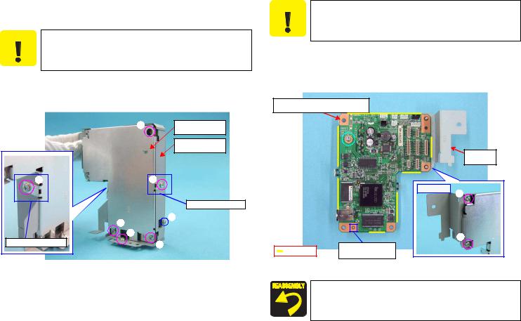
L800/L801 |
Revision A |
|
|
̈Disassembling the Main Board Unit
1.Remove the Main Board Unit (p.27).
̈Do not apply unnecessary force on the screw receiving parts of
C A U T IO N
the Lower Shield Plate M/B, as they are easy to deform.
̈When assembling or disassembling the Upper Shield Plate M/B,
be careful of its sharp edges.
2.Remove the seven screws and remove the Upper Shield Plate M/B.
•Screw  (6 pcs.): C.B.S. M3x6 (tightening torque: 5-7 kgf.cm)
•Screw  (1 pc.): C.P. M3x6 (tightening torque: 4-6 kgf.cm)
(The numbers shown in the figure indicate the order of tightening the screws.)
Be careful of the sharp edges shown in the figure below when
C A U T IO N
assembling or reassembling.
3.Remove the two screws and remove the Shield Plate M/B Sub.
•Screw  (2 pcs.): C.B.S. M3x6 (tightening torque: 4-6 kgf.cm)
(The numbers shown in the figure indicate the order of tightening the screws.)
4.Remove the screw and remove the Main Board Unit.
•Screw  C.B.S. M3x10 (tightening torque: 4-6 kgf.cm)
Upper Side: Main Board
Lower Side: Lower Shield Plate M/B
5 |
|
Lower Shield Plate |
|
|
|
M/B |
|
|
|
Upper Shield Plate |
|
|
|
M/B |
|
|
|
|
ShieldPlate |
|
|
|
M/B Sub |
3 |
2 |
|
|
|
|
|
[Rear Side] |
|
|
|
1 |
|
|
Screw Receiving Part |
|
7 |
|
1 |
|
|
|
|
|
4 |
|
|
2 |
Screw Receiving Part |
|
|
|
6 |
|
|
|
|
Sharp edge |
Positioning Hole and |
|
|
|
||
|
|
Guide Pin |
|
|
|
|
Figure 1-27. Removing the Upper Shield Plate M/B |
Figure 1-28. Removing the Main Board |
|
̈ When installing the Main Board, match the positioning hole with the guide pin shown in Fig.1-28.
̈ Tighten the screws in the order given in Fig.1-27 (p.29), Fig.1-28.
Disassembly/Reassembly |
Main Board Unit |
29 |
|
|
|
CONFIDENTIAL
Downloaded from www.Manualslib.com manuals search engine
 Loading...