


 Loading...
TM-L90/TM-L90 Peeler
Technical Reference
Guide
EPSON |
English |
|
410019401

TM-L90/TM-L90 with Peeler Technical Reference Guide
Cautions
No part of this document may be reproduced, stored in a retrieval system, or transmitted in any form or by any means, electronic, mechanical, photocopying, recording, or otherwise, without the prior written permission of Seiko Epson Corporation.
The contents of this document are subject to change without notice. Please contact us for the latest information.
While every precaution has been taken in the preparation of this document, Seiko Epson Corporation assumes no responsibility for errors or omissions.
Neither is any liability assumed for damages resulting from the use of the information contained herein.
Neither Seiko Epson Corporation nor its affiliates shall be liable to the purchaser of this product or third parties for damages, losses, costs, or expenses incurred by the purchaser or third parties as a result of: accident, misuse, or abuse of this product or unauthorized modifications, repairs, or alterations to this product, or (excluding the U.S.) failure to strictly comply with Seiko Epson Corporation’s operating and maintenance instructions.
Seiko Epson Corporation shall not be liable against any damages or problems arising from the use of any options or any consumable products other than those designated as Original EPSON Products or EPSON Approved Products by Seiko Epson Corporation.
Trademarks
EPSON® and ESC/POS® are registered trademarks of Seiko Epson Corporation
ESC/POS® Command System
EPSON has been taking industryinitiatives with its own POS printer command system (ESC/POS). ESC/POS has a large number of commands, including patented ones. Its high scalability enables users to build versatile POS systems. The system is compatible with all types of EPSON POS printers and displays. Moreover, its flexibility makes it easy to upgrade in the future. The functionality and the user-friendliness are valued around the world.
Revision Table
Rev |
Page |
Description |
|
|
|
Rev. A |
all pages |
Newly authorized |
|
|
|
Rev. B |
all pages |
Descriptions of horizontal installation deleted |
|
|
|
Rev. B |
i |

For Safety
Key to Symbols
The symbols in this manual are identified by their level of importance, as defined below. Read the following carefully before handling the product.
 WARNING:
You must follow warnings carefully to avoid serious bodily injury.
 CAUTION:
Provides information that must be observed to prevent damage to the equipment or loss of data.
Possibility of sustaining physical injuries.
Possibility of causing physical damage.
Possibility of causing information loss.
 Note:
Note:
Provides important information and useful tips on handling the equipment.
ii |
Rev. B |

TM-L90/TM-L90 with Peeler Technical Reference Guide
Warnings
 WARNING:
Shut down your equipment immediately if it produces smoke, a strange odor, or unusual noise. Continued use may lead to fire or electric shock. Immediately unplug the equipment.
Only disassemble this product as described in this manual. Do not make modifications to the unit. Tampering with this product may result in injury, fire, or electric shock.
Do not install this product or handle cables during a thunderstorm in order to avoid risk of electric shock.
Be sure to use the specified power source. Connection to an improper power source may cause fire or shock.
Never insert or disconnect the power plug with wet hands. Doing so may result in severe shock.
Do not allow foreign matter to fall into the equipment. Penetration by foreign objects may lead to fire or electric shock.
If water or other liquid spills into this equipment, turn off the power supply switch and unplug the power cord immediately. Continued usage may lead to fire or electric shock.
Do not place multiple loads on power outlet. Overloading the outlet may lead to fire. Always supply power directly from a standard domestic power outlet.
Handle the power cord with care. Improper handling may lead to fire or electric shock.
•Do not modify or attempt to repair the cord.
•Do not place any heavy object on top of the cord.
•Avoid excessive bending, twisting, and pulling.
•Do not place the cord near heating equipment.
•Check that the plug is clean before plugging it in.
•Be sure to push the plug all the way in.
Rev. B |
iii |

Cautions
 CAUTION:
Do not connect cables in ways other than those mentioned in this manual. Different connections may cause equipment damage and burning.
Be sure to set this equipment on a firm, stable horizontal surface. Product may break or cause injury if it falls.
Do not use in locations subject to high humidity or dust levels. Excessive humidity and dust may cause equipment damage, fire, or shock.
Do not place heavy objects on top of this equipment. Never stand or lean on this equipment. Equipment may fall or collapse, causing breakage and possible injury.
To ensure safety, unplug this equipment prior to leaving it unused for an extended period.
Parts on the circuit board may become hot during operation. Therefore, wait approximately 10 minutes after turning the power off before touching them.
To avoid injury, take care not to insert fingers or any part of the hand in the roll paper opening where the manual cutter is installed.
Do not open the roll paper cover without taking the necessary precautions, as this can result in injury from the autocutter fixed blade.
Be sure to replace the batteries correctly. Improper replacement may cause a battery burst. Only use batteries provided by EPSON. Follow the requirements of your regional to properly dispose of used batteries.
Modular Connector
Use the modular connectors specifically designed for the cash drawer for this product. Do not connect these connectors to an ordinary telephone line.
iv |
Rev. B |

TM-L90/TM-L90 with Peeler Technical Reference Guide
About This Manual
Aim of the Manual
This manual was created to provide all information necessary for system planning, design, installations and application of the printer for designers and developers of POS systems.
Manual Content
The manual is made up of the following sections:
Chapter 1 |
Product Overview |
Chapter 2 |
Setup |
Chapter 3 |
Connecting the Host Computer and Options |
Chapter 4 |
Application Development Information |
Chapter 5 |
ESC/POS Command Related Information |
Chapter 6 |
Product Specifications |
Appendix A |
Interfaces and Connectors |
Appendix B |
Consumable Supplies Specifications |
Appendix C |
Character Code Table |
Appendix D |
Option Specifications |
Appendix E |
Maintenance |
Appendix F |
Troubleshooting |
Appendix G |
Shipping Procedures |
Related Documentation
The following documents also relate to the TM-L90 / TM-L90 peeler specification.
Name of document |
Description |
|
|
TM-L90 User’s Manual |
Comes with the printer. |
|
Provides information to enable POS operators to use the |
|
TM-L90 safely and correctly. |
|
|
TM-L90 with Peeler User’s Manual |
Comes with the printer. |
|
Provides information to enable POS operators to use the |
|
TM-L90 peeler specification safely and correctly. |
|
|
ESC/POS Application Programming Guide |
Provides detailed ESC/POS command information. |
|
Contact us to obtain this guide. |
|
|
Rev. B |
v |

vi |
Rev. B |
TM-L90/TM-L90 with Peeler Technical Reference Guide
Contents
Revision Table . . . . . . . . . . . . . . . . . . . . . . . . . . . . . . . . . . . . . . . . . . . . . . . . . . . . . . . . . . . . . . . . . . . . . . . . . . . 1-i
For Safety . . . . . . . . . . . . . . . . . . . . . . . . . . . . . . . . . . . . . . . . . . . . . . . . . . . . . . . . . . . . . . . . . . . . . . . . . . . . . . 1-ii
Key to Symbols . . . . . . . . . . . . . . . . . . . . . . . . . . . . . . . . . . . . . . . . . . . . . . . . . . . . . . . . . . . . . . . . . . . . . . 1-ii
Warnings . . . . . . . . . . . . . . . . . . . . . . . . . . . . . . . . . . . . . . . . . . . . . . . . . . . . . . . . . . . . . . . . . . . . . . . . . . . 1-iii
Cautions . . . . . . . . . . . . . . . . . . . . . . . . . . . . . . . . . . . . . . . . . . . . . . . . . . . . . . . . . . . . . . . . . . . . . . . . . . . . 1-iv
Modular Connector . . . . . . . . . . . . . . . . . . . . . . . . . . . . . . . . . . . . . . . . . . . . . . . . . . . . . . . . . . . . . . . . . . . . . . 1-iv
About This Manual . . . . . . . . . . . . . . . . . . . . . . . . . . . . . . . . . . . . . . . . . . . . . . . . . . . . . . . . . . . . . . . . . . . . . . . 1-v
Aim of the Manual . . . . . . . . . . . . . . . . . . . . . . . . . . . . . . . . . . . . . . . . . . . . . . . . . . . . . . . . . . . . . . . . . . . 1-v
Manual Content . . . . . . . . . . . . . . . . . . . . . . . . . . . . . . . . . . . . . . . . . . . . . . . . . . . . . . . . . . . . . . . . . . . . . 1-v
Related Documentation . . . . . . . . . . . . . . . . . . . . . . . . . . . . . . . . . . . . . . . . . . . . . . . . . . . . . . . . . . . . . . 1-v
Chapter 1 Product Overview
1.1 Product Structure . . . . . . . . . . . . . . . . . . . . . . . . . . . . . . . . . . . . . . . . . . . . . . . . . . . . . . . . . . . . . . . . . . . . . 1-1 1.1.1 Models . . . . . . . . . . . . . . . . . . . . . . . . . . . . . . . . . . . . . . . . . . . . . . . . . . . . . . . . . . . . . . . . . . . . . . . . . 1-1 1.1.2 Accessories . . . . . . . . . . . . . . . . . . . . . . . . . . . . . . . . . . . . . . . . . . . . . . . . . . . . . . . . . . . . . . . . . . . . . 1-1 1.1.3 Option . . . . . . . . . . . . . . . . . . . . . . . . . . . . . . . . . . . . . . . . . . . . . . . . . . . . . . . . . . . . . . . . . . . . . . . . . 1-2 1.2 Name and Description of Each Part . . . . . . . . . . . . . . . . . . . . . . . . . . . . . . . . . . . . . . . . . . . . . . . . . . . . . 1-3 1.2.1 Part Names (TM-L90) . . . . . . . . . . . . . . . . . . . . . . . . . . . . . . . . . . . . . . . . . . . . . . . . . . . . . . . . . . . . . 1-3 1.2.2 Part names (TM-L90 peeler specification) . . . . . . . . . . . . . . . . . . . . . . . . . . . . . . . . . . . . . . . . . . . 1-4 1.2.3 Control Panel . . . . . . . . . . . . . . . . . . . . . . . . . . . . . . . . . . . . . . . . . . . . . . . . . . . . . . . . . . . . . . . . . . . 1-5 1.2.4 Power Switch . . . . . . . . . . . . . . . . . . . . . . . . . . . . . . . . . . . . . . . . . . . . . . . . . . . . . . . . . . . . . . . . . . . 1-7 1.2.5 Power switch cover . . . . . . . . . . . . . . . . . . . . . . . . . . . . . . . . . . . . . . . . . . . . . . . . . . . . . . . . . . . . . . 1-8 1.2.6 Mode switch (TM-L90 peeler specification only) . . . . . . . . . . . . . . . . . . . . . . . . . . . . . . . . . . . . . . 1-8 1.2.7 Connectors . . . . . . . . . . . . . . . . . . . . . . . . . . . . . . . . . . . . . . . . . . . . . . . . . . . . . . . . . . . . . . . . . . . . . 1-9
Chapter 2 Setup
2.1 |
Setup Flow . . . . . . . . . . . . . . . . . . . . . . . . . . . . . . . . . . . . . . . . . . . . . . . . . . . . . . . . . . . . . . . . . . . . . . . . . . . |
2-1 |
2.2 |
Installation Procedures . . . . . . . . . . . . . . . . . . . . . . . . . . . . . . . . . . . . . . . . . . . . . . . . . . . . . . . . . . . . . . . . |
2-2 |
|
2.2.1 Precaution For Installation . . . . . . . . . . . . . . . . . . . . . . . . . . . . . . . . . . . . . . . . . . . . . . . . . . . . . . . . |
2-2 |
|
2.2.2 Instructions for Installation . . . . . . . . . . . . . . . . . . . . . . . . . . . . . . . . . . . . . . . . . . . . . . . . . . . . . . . . . |
2-2 |
2.3 |
Adjusting Roll Paper Near-End Detection Position . . . . . . . . . . . . . . . . . . . . . . . . . . . . . . . . . . . . . . . . . . |
2-4 |
|
2.3.1 With TM-L90 . . . . . . . . . . . . . . . . . . . . . . . . . . . . . . . . . . . . . . . . . . . . . . . . . . . . . . . . . . . . . . . . . . . . . |
2-4 |
|
2.3.2 With the TM-L90 peeler specification . . . . . . . . . . . . . . . . . . . . . . . . . . . . . . . . . . . . . . . . . . . . . . . |
2-8 |
2.4 |
Connecting Power Supply Unit (PS-180) . . . . . . . . . . . . . . . . . . . . . . . . . . . . . . . . . . . . . . . . . . . . . . . . . . |
2-12 |
|
2.4.1 Attaching Power Supply Unit . . . . . . . . . . . . . . . . . . . . . . . . . . . . . . . . . . . . . . . . . . . . . . . . . . . . . . |
2-12 |
|
2.4.2 Caution about Power Supply unit and Supply Voltage . . . . . . . . . . . . . . . . . . . . . . . . . . . . . . . . |
2-13 |
2.5 |
Autocutter settings (TM-L90 only) . . . . . . . . . . . . . . . . . . . . . . . . . . . . . . . . . . . . . . . . . . . . . . . . . . . . . . . . |
2-14 |
2.6 |
Setting Roll Paper Width . . . . . . . . . . . . . . . . . . . . . . . . . . . . . . . . . . . . . . . . . . . . . . . . . . . . . . . . . . . . . . . |
2-17 |
2.7 |
DIP Switch Settings . . . . . . . . . . . . . . . . . . . . . . . . . . . . . . . . . . . . . . . . . . . . . . . . . . . . . . . . . . . . . . . . . . . . |
2-19 |
2.8 |
Setting Memory Switches . . . . . . . . . . . . . . . . . . . . . . . . . . . . . . . . . . . . . . . . . . . . . . . . . . . . . . . . . . . . . . |
2-21 |
|
2.8.1 Items that can be set in the memory switch setting mode . . . . . . . . . . . . . . . . . . . . . . . . . . . . . |
2-22 |
|
2.8.2 Starting the Memory Switch Setting mode . . . . . . . . . . . . . . . . . . . . . . . . . . . . . . . . . . . . . . . . . . . |
2-23 |
|
2.8.3 Ending Memory Switch Setting mode . . . . . . . . . . . . . . . . . . . . . . . . . . . . . . . . . . . . . . . . . . . . . . . |
2-24 |
|
2.8.4 Operating procedure of Memory Switch Settings . . . . . . . . . . . . . . . . . . . . . . . . . . . . . . . . . . . . . |
2-25 |
2.9 |
Memory Switch Functions . . . . . . . . . . . . . . . . . . . . . . . . . . . . . . . . . . . . . . . . . . . . . . . . . . . . . . . . . . . . . . |
2-33 |
|
2.9.1 TM-L90 memory switch settings . . . . . . . . . . . . . . . . . . . . . . . . . . . . . . . . . . . . . . . . . . . . . . . . . . . . |
2-33 |
|
2.9.2 TM-L90 peeler specification memory switch settings . . . . . . . . . . . . . . . . . . . . . . . . . . . . . . . . . . |
2-36 |
2.10 Paper Loading Method . . . . . . . . . . . . . . . . . . . . . . . . . . . . . . . . . . . . . . . . . . . . . . . . . . . . . . . . . . . . . . . |
2-39 |
|
|
2.10.1 With TM-L90 . . . . . . . . . . . . . . . . . . . . . . . . . . . . . . . . . . . . . . . . . . . . . . . . . . . . . . . . . . . . . . . . . . . . |
2-39 |
2.10.2 With the TM-L90 peeler specification . . . . . . . . . . . . . . . . . . . . . . . . . . . . . . . . . . . . . . . . . . . . . . 2-40 2.10.3 Setting Paper Layout . . . . . . . . . . . . . . . . . . . . . . . . . . . . . . . . . . . . . . . . . . . . . . . . . . . . . . . . . . . 2-44 2.10.4 Clearing Paper Layout Setting . . . . . . . . . . . . . . . . . . . . . . . . . . . . . . . . . . . . . . . . . . . . . . . . . . . . 2-48 2.11 TM Setup Items (Summary) . . . . . . . . . . . . . . . . . . . . . . . . . . . . . . . . . . . . . . . . . . . . . . . . . . . . . . . . . . . . 2-49 2.12 Operating Mode (Panel Switch Operation) . . . . . . . . . . . . . . . . . . . . . . . . . . . . . . . . . . . . . . . . . . . . . . 2-51 2.12.1 Self Test Mode . . . . . . . . . . . . . . . . . . . . . . . . . . . . . . . . . . . . . . . . . . . . . . . . . . . . . . . . . . . . . . . . . 2-51
Chapter 3 Connecting to the Host Computer and Options
3.1 |
Connecting the Cable . . . . . . . . . . . . . . . . . . . . . . . . . . . . . . . . . . . . . . . . . . . . . . . . . . . . . . . . . . . . . . . . |
3-1 |
3.2 |
Connecting to the Host Computer . . . . . . . . . . . . . . . . . . . . . . . . . . . . . . . . . . . . . . . . . . . . . . . . . . . . . . |
3-2 |
|
3.2.1 With the RS-232C interface . . . . . . . . . . . . . . . . . . . . . . . . . . . . . . . . . . . . . . . . . . . . . . . . . . . . . . . |
3-2 |
|
3.2.2 With the parallel (IEEE1284) interface . . . . . . . . . . . . . . . . . . . . . . . . . . . . . . . . . . . . . . . . . . . . . . . |
3-5 |
|
3.2.3 With the USB interface . . . . . . . . . . . . . . . . . . . . . . . . . . . . . . . . . . . . . . . . . . . . . . . . . . . . . . . . . . . |
3-5 |
|
3.2.4 With the Ethernet interface 'IEEE802.3' (TM-L90 only) . . . . . . . . . . . . . . . . . . . . . . . . . . . . . . . . . . |
3-7 |
3.3 |
Connecting to the Drawer . . . . . . . . . . . . . . . . . . . . . . . . . . . . . . . . . . . . . . . . . . . . . . . . . . . . . . . . . . . . . |
3-9 |
Chapter 4 Application Development Information
4.1 Introduction of Control Methods . . . . . . . . . . . . . . . . . . . . . . . . . . . . . . . . . . . . . . . . . . . . . . . . . . . . . . . . |
4-1 |
4.1.1 Windows Driver (EPSON Advanced Printer Driver) . . . . . . . . . . . . . . . . . . . . . . . . . . . . . . . . . . . . |
4-1 |
4.1.1.1 EPSON Advanced Printer Driver Overview . . . . . . . . . . . . . . . . . . . . . . . . . . . . . . . . . . . . . . |
4-1 |
4.1.1.2 EPSON Advanced Printer Driver Contents . . . . . . . . . . . . . . . . . . . . . . . . . . . . . . . . . . . . . . |
4-2 |
4.1.1.3 EPSON Advanced Printer Driver Support Environment . . . . . . . . . . . . . . . . . . . . . . . . . . . . |
4-3 |
4.1.1.4 Driver Information and Download Destination . . . . . . . . . . . . . . . . . . . . . . . . . . . . . . . . . . |
4-4 |
4.1.2 EPSON OPOS ADK . . . . . . . . . . . . . . . . . . . . . . . . . . . . . . . . . . . . . . . . . . . . . . . . . . . . . . . . . . . . . . . |
4-4 |
4.1.2.1 EPSON OPOS ADK (OPOS Control) Overview . . . . . . . . . . . . . . . . . . . . . . . . . . . . . . . . . . . |
4-5 |
4.1.2.2 EPSON OPOS ADK Contents . . . . . . . . . . . . . . . . . . . . . . . . . . . . . . . . . . . . . . . . . . . . . . . . . |
4-5 |
4.1.2.3 EPSON OPOS ADK Support Environment . . . . . . . . . . . . . . . . . . . . . . . . . . . . . . . . . . . . . . . |
4-6 |
4.1.2.4 Driver Information and Download Destination . . . . . . . . . . . . . . . . . . . . . . . . . . . . . . . . . . |
4-7 |
4.1.3 ESC/POS Commands . . . . . . . . . . . . . . . . . . . . . . . . . . . . . . . . . . . . . . . . . . . . . . . . . . . . . . . . . . . . |
4-7 |
4.1.4 Various Utilities . . . . . . . . . . . . . . . . . . . . . . . . . . . . . . . . . . . . . . . . . . . . . . . . . . . . . . . . . . . . . . . . . . |
4-7 |
4.1.4.1 Address Setup Utility for Ethernet Interface (for UB-E01/UB-E02) . . . . . . . . . . . . . . . . . . . . |
4-7 |
4.1.4.2 Electronic Logo Registration Utility for NVRAM . . . . . . . . . . . . . . . . . . . . . . . . . . . . . . . . . . |
4-7 |
4.1.4.3 TM Printer Memory Switch Setup Utility . . . . . . . . . . . . . . . . . . . . . . . . . . . . . . . . . . . . . . . . . |
4-7 |
4.1.4.4 USB Interface ID Code Rewrite Utility . . . . . . . . . . . . . . . . . . . . . . . . . . . . . . . . . . . . . . . . . . |
4-7 |
4.2 Sensors . . . . . . . . . . . . . . . . . . . . . . . . . . . . . . . . . . . . . . . . . . . . . . . . . . . . . . . . . . . . . . . . . . . . . . . . . . . . . |
4-8 |
4.2.1 Paper sensors . . . . . . . . . . . . . . . . . . . . . . . . . . . . . . . . . . . . . . . . . . . . . . . . . . . . . . . . . . . . . . . . . . . |
4-8 |
4.2.1.1 Roll paper near-end sensor . . . . . . . . . . . . . . . . . . . . . . . . . . . . . . . . . . . . . . . . . . . . . . . . . . |
4-8 |
4.2.1.2 Roll Paper End Sensor . . . . . . . . . . . . . . . . . . . . . . . . . . . . . . . . . . . . . . . . . . . . . . . . . . . . . . . |
4-8 |
4.2.2 Printer Cover Sensor . . . . . . . . . . . . . . . . . . . . . . . . . . . . . . . . . . . . . . . . . . . . . . . . . . . . . . . . . . . . . |
4-8 |
4.2.2.1 Roll Paper Cover Open Sensor . . . . . . . . . . . . . . . . . . . . . . . . . . . . . . . . . . . . . . . . . . . . . . . |
4-8 |
4.2.2.2 Offline . . . . . . . . . . . . . . . . . . . . . . . . . . . . . . . . . . . . . . . . . . . . . . . . . . . . . . . . . . . . . . . . . . . . |
4-9 |
4.2.2.3 Busy state . . . . . . . . . . . . . . . . . . . . . . . . . . . . . . . . . . . . . . . . . . . . . . . . . . . . . . . . . . . . . . . . . |
4-9 |
4.2.2.4 Receive buffer . . . . . . . . . . . . . . . . . . . . . . . . . . . . . . . . . . . . . . . . . . . . . . . . . . . . . . . . . . . . . |
4-10 |
4.2.3 Label peeling sensor (peeler specification only) . . . . . . . . . . . . . . . . . . . . . . . . . . . . . . . . . . . . . |
4-10 |
4.3 Setting of Paper Width . . . . . . . . . . . . . . . . . . . . . . . . . . . . . . . . . . . . . . . . . . . . . . . . . . . . . . . . . . . . . . . . |
4-11 |
4.4 Print Density . . . . . . . . . . . . . . . . . . . . . . . . . . . . . . . . . . . . . . . . . . . . . . . . . . . . . . . . . . . . . . . . . . . . . . . . . |
4-11 |
4.5 Print Speed . . . . . . . . . . . . . . . . . . . . . . . . . . . . . . . . . . . . . . . . . . . . . . . . . . . . . . . . . . . . . . . . . . . . . . . . . . |
4-11 |
4.5.1 Paper to use for high speed . . . . . . . . . . . . . . . . . . . . . . . . . . . . . . . . . . . . . . . . . . . . . . . . . . . . . . . |
4-11 |
4.6 Barcode Printing . . . . . . . . . . . . . . . . . . . . . . . . . . . . . . . . . . . . . . . . . . . . . . . . . . . . . . . . . . . . . . . . . . . . . |
4-12 |
4.7 CODE 128 Barcode . . . . . . . . . . . . . . . . . . . . . . . . . . . . . . . . . . . . . . . . . . . . . . . . . . . . . . . . . . . . . . . . . . . |
4-12 |
4.8 Precautions for Two-Dimensional Code Printing . . . . . . . . . . . . . . . . . . . . . . . . . . . . . . . . . . . . . . . . . . . |
4-16 |
4.9 Two-Color Printing . . . . . . . . . . . . . . . . . . . . . . . . . . . . . . . . . . . . . . . . . . . . . . . . . . . . . . . . . . . . . . . . . . . . |
4-16 |
4.10 NV Memory . . . . . . . . . . . . . . . . . . . . . . . . . . . . . . . . . . . . . . . . . . . . . . . . . . . . . . . . . . . . . . . . . . . . . . . . |
4-16 |
4.11 FAQ List . . . . . . . . . . . . . . . . . . . . . . . . . . . . . . . . . . . . . . . . . . . . . . . . . . . . . . . . . . . . . . . . . . . . . . . . . . . . |
4-17 |
TM-L90/TM-L90 with Peeler Technical Reference Guide
Chapter 5 ESC/POS Command-Related Information
5.1 |
TM Printer Operation Performed When Power Supply Switch is Disabled . . . . . . . . . . . . . . . . . . . . . . . |
5-1 |
|
5.1.1 Power Supply Switch-Related User Operation List . . . . . . . . . . . . . . . . . . . . . . . . . . . . . . . . . . . . . |
5-1 |
|
5.1.2 Power Off Control by the Host . . . . . . . . . . . . . . . . . . . . . . . . . . . . . . . . . . . . . . . . . . . . . . . . . . . . . |
5-1 |
|
5.1.2.1 When the Power Supply Switch is Enabled . . . . . . . . . . . . . . . . . . . . . . . . . . . . . . . . . . . . . |
5-2 |
|
5.1.2.2 When the Power Supply Switch is Disabled . . . . . . . . . . . . . . . . . . . . . . . . . . . . . . . . . . . . . |
5-2 |
5.2 |
Head Divided Control . . . . . . . . . . . . . . . . . . . . . . . . . . . . . . . . . . . . . . . . . . . . . . . . . . . . . . . . . . . . . . . . . |
5-2 |
5.3 |
Control After Paper Cut . . . . . . . . . . . . . . . . . . . . . . . . . . . . . . . . . . . . . . . . . . . . . . . . . . . . . . . . . . . . . . . |
5-2 |
5.4 NV Memory . . . . . . . . . . . . . . . . . . . . . . . . . . . . . . . . . . . . . . . . . . . . . . . . . . . . . . . . . . . . . . . . . . . . . . . . . . |
5-2 |
|
5.5 |
Customizing Printer . . . . . . . . . . . . . . . . . . . . . . . . . . . . . . . . . . . . . . . . . . . . . . . . . . . . . . . . . . . . . . . . . . . |
5-3 |
|
5.5.1 Printer initial setting up . . . . . . . . . . . . . . . . . . . . . . . . . . . . . . . . . . . . . . . . . . . . . . . . . . . . . . . . . . . |
5-3 |
|
5.5.2 Changing command default values . . . . . . . . . . . . . . . . . . . . . . . . . . . . . . . . . . . . . . . . . . . . . . . |
5-3 |
|
5.5.3 Using the NV Memory . . . . . . . . . . . . . . . . . . . . . . . . . . . . . . . . . . . . . . . . . . . . . . . . . . . . . . . . . . . . |
5-3 |
5.6 Printer Status . . . . . . . . . . . . . . . . . . . . . . . . . . . . . . . . . . . . . . . . . . . . . . . . . . . . . . . . . . . . . . . . . . . . . . . . . |
5-4 |
|
|
5.6.1 Hexadecimal Dump Mode . . . . . . . . . . . . . . . . . . . . . . . . . . . . . . . . . . . . . . . . . . . . . . . . . . . . . . . |
5-4 |
Chapter 6 Product Specifications
6.1 Product Specifications . . . . . . . . . . . . . . . . . . . . . . . . . . . . . . . . . . . . . . . . . . . . . . . . . . . . . . . . . . . . . . . . 6-1 6.1.1 TM-L90 . . . . . . . . . . . . . . . . . . . . . . . . . . . . . . . . . . . . . . . . . . . . . . . . . . . . . . . . . . . . . . . . . . . . . . . . . 6-1 6.1.2 TM-L90 peeler specification . . . . . . . . . . . . . . . . . . . . . . . . . . . . . . . . . . . . . . . . . . . . . . . . . . . . . . . 6-3 6.2 Print Specifications . . . . . . . . . . . . . . . . . . . . . . . . . . . . . . . . . . . . . . . . . . . . . . . . . . . . . . . . . . . . . . . . . . . . 6-4
6.3 Reliability . . . . . . . . . . . . . . . . . . . . . . . . . . . . . . . . . . . . . . . . . . . . . . . . . . . . . . . . . . . . . . . . . . . . . . . . . . . . 6-5 6.3.1 TM-L90 . . . . . . . . . . . . . . . . . . . . . . . . . . . . . . . . . . . . . . . . . . . . . . . . . . . . . . . . . . . . . . . . . . . . . . . . . 6-5 6.3.2 TM-L90 peeler specification . . . . . . . . . . . . . . . . . . . . . . . . . . . . . . . . . . . . . . . . . . . . . . . . . . . . . . . 6-7 6.4 Character Specifications . . . . . . . . . . . . . . . . . . . . . . . . . . . . . . . . . . . . . . . . . . . . . . . . . . . . . . . . . . . . . . 6-8
6.5 Paper Feed Specifications . . . . . . . . . . . . . . . . . . . . . . . . . . . . . . . . . . . . . . . . . . . . . . . . . . . . . . . . . . . . . 6-9 6.5.1 Precautions for Printing and Paper Feed . . . . . . . . . . . . . . . . . . . . . . . . . . . . . . . . . . . . . . . . . . . . 6-9 6.6 Paper Specifications . . . . . . . . . . . . . . . . . . . . . . . . . . . . . . . . . . . . . . . . . . . . . . . . . . . . . . . . . . . . . . . . . . 6-9
6.7 Printing Area . . . . . . . . . . . . . . . . . . . . . . . . . . . . . . . . . . . . . . . . . . . . . . . . . . . . . . . . . . . . . . . . . . . . . . . . . 6-10 6.7.1 Thermal Paper . . . . . . . . . . . . . . . . . . . . . . . . . . . . . . . . . . . . . . . . . . . . . . . . . . . . . . . . . . . . . . . . . . 6-10 6.7.2 Label . . . . . . . . . . . . . . . . . . . . . . . . . . . . . . . . . . . . . . . . . . . . . . . . . . . . . . . . . . . . . . . . . . . . . . . . . . 6-11 6.8 Printing Position in Relation to Cutter Position (TM-L90) . . . . . . . . . . . . . . . . . . . . . . . . . . . . . . . . . . . . . . 6-12
6.9 Printing Position, Peeling Position, Manual Cutter Position (TM-L90 Peeler Specification) . . . . . . . . . . 6-13 6.10 Overview of External Dimensions . . . . . . . . . . . . . . . . . . . . . . . . . . . . . . . . . . . . . . . . . . . . . . . . . . . . . . . 6-14 6.10.1 Operating specifications . . . . . . . . . . . . . . . . . . . . . . . . . . . . . . . . . . . . . . . . . . . . . . . . . . . . . . . . 6-16
Appendix A Interface And Connectors
A.1 |
RS-232 Serial Interface . . . . . . . . . . . . . . . . . . . . . . . . . . . . . . . . . . . . . . . . . . . . . . . . . . . . . . . . . . . . . . . . |
A-1 |
|
A.1.1 Interface board specifications (RS-232 standard) . . . . . . . . . . . . . . . . . . . . . . . . . . . . . . . . . . . . |
A-1 |
|
A.1.2 Functions of each connector pin . . . . . . . . . . . . . . . . . . . . . . . . . . . . . . . . . . . . . . . . . . . . . . . . . |
A-2 |
|
A.1.3 XON/XOFF . . . . . . . . . . . . . . . . . . . . . . . . . . . . . . . . . . . . . . . . . . . . . . . . . . . . . . . . . . . . . . . . . . . . . |
A-3 |
|
A.1.4 Code . . . . . . . . . . . . . . . . . . . . . . . . . . . . . . . . . . . . . . . . . . . . . . . . . . . . . . . . . . . . . . . . . . . . . . . . . |
A-3 |
A.2 |
IEEE1284 Parallel Interface . . . . . . . . . . . . . . . . . . . . . . . . . . . . . . . . . . . . . . . . . . . . . . . . . . . . . . . . . . . . . |
A-4 |
|
A.2.1 Mode . . . . . . . . . . . . . . . . . . . . . . . . . . . . . . . . . . . . . . . . . . . . . . . . . . . . . . . . . . . . . . . . . . . . . . . . . |
A-4 |
|
A.2.2 Interface Signals . . . . . . . . . . . . . . . . . . . . . . . . . . . . . . . . . . . . . . . . . . . . . . . . . . . . . . . . . . . . . . . . |
A-5 |
Appendix B Consumable Specifications
B.1 TM-L90 Roll Paper . . . . . . . . . . . . . . . . . . . . . . . . . . . . . . . . . . . . . . . . . . . . . . . . . . . . . . . . . . . . . . . . . . . . . B-1 B.1.1 Receipt Roll Paper . . . . . . . . . . . . . . . . . . . . . . . . . . . . . . . . . . . . . . . . . . . . . . . . . . . . . . . . . . . . . . . B-1 B.1.1.1 Specified Receipt Roll Paper . . . . . . . . . . . . . . . . . . . . . . . . . . . . . . . . . . . . . . . . . . . . . . . . . B-2 B.1.1.2 Specified Original Roll Paper . . . . . . . . . . . . . . . . . . . . . . . . . . . . . . . . . . . . . . . . . . . . . . . . . B-2 B.1.1.3 Print Density Adjustment . . . . . . . . . . . . . . . . . . . . . . . . . . . . . . . . . . . . . . . . . . . . . . . . . . . . . B-3 B.1.1.4 Paper to Use for High Speed . . . . . . . . . . . . . . . . . . . . . . . . . . . . . . . . . . . . . . . . . . . . . . . . . B-3
B.1.1.5 In case that paper other than the specified original paper is used . . . . . . . . . . . . . . . . . |
B-4 |
B.1.1.6 Requirements for Black Mark Position for Receipt Paper . . . . . . . . . . . . . . . . . . . . . . . . . . |
B-4 |
B.1.2 Die-Cut Label Roll Paper . . . . . . . . . . . . . . . . . . . . . . . . . . . . . . . . . . . . . . . . . . . . . . . . . . . . . . . . . |
B-5 |
B.1.2.1 Die-Cut Label Paper . . . . . . . . . . . . . . . . . . . . . . . . . . . . . . . . . . . . . . . . . . . . . . . . . . . . . . . . |
B-5 |
B.1.2.2 Specified Die-Cut Label Roll Paper Specifications . . . . . . . . . . . . . . . . . . . . . . . . . . . . . . . |
B-5 |
B.1.2.3 Specified Original Paper . . . . . . . . . . . . . . . . . . . . . . . . . . . . . . . . . . . . . . . . . . . . . . . . . . . . |
B-6 |
B.1.2.4 Print Density Adjustment . . . . . . . . . . . . . . . . . . . . . . . . . . . . . . . . . . . . . . . . . . . . . . . . . . . . . |
B-6 |
B.1.2.5 Paper to Use for High Speed . . . . . . . . . . . . . . . . . . . . . . . . . . . . . . . . . . . . . . . . . . . . . . . . . |
B-6 |
B.1.2.6 In case that paper other than the specified original paper is used . . . . . . . . . . . . . . . . . |
B-7 |
B.1.2.7 Requirements for Die-Cut Label Paper Thickness, Peeling Strength, |
|
and Adhesive Agent . . . . . . . . . . . . . . . . . . . . . . . . . . . . . . . . . . . . . . . . . . . . . . . . . . . . . . . . . . . . . |
B-7 |
B.1.2.8 Requirements for Die-Cut Label Size . . . . . . . . . . . . . . . . . . . . . . . . . . . . . . . . . . . . . . . . . . . |
B-8 |
B.1.2.9 Requirements for Transparency Rate of Die-Cut Label Paper . . . . . . . . . . . . . . . . . . . . . |
B-9 |
B.1.2.10 Requirements for Black Mark Position for Die-Cut Label Paper . . . . . . . . . . . . . . . . . . . . |
B-9 |
B.1.2.11 Requirements for Black Mark Position I . . . . . . . . . . . . . . . . . . . . . . . . . . . . . . . . . . . . . . . . |
B-9 |
B.1.2.12 Requirements for Black Mark Position II . . . . . . . . . . . . . . . . . . . . . . . . . . . . . . . . . . . . . . . |
B-10 |
B.1.3 Continuous Label Roll Paper . . . . . . . . . . . . . . . . . . . . . . . . . . . . . . . . . . . . . . . . . . . . . . . . . . . . . . |
B-11 |
B.1.3.1 Continuous Label Paper . . . . . . . . . . . . . . . . . . . . . . . . . . . . . . . . . . . . . . . . . . . . . . . . . . . . . |
B-11 |
B.1.3.2 Specified Continuous Label Roll Paper . . . . . . . . . . . . . . . . . . . . . . . . . . . . . . . . . . . . . . . . |
B-11 |
B.1.3.3 Print Density Adjustment . . . . . . . . . . . . . . . . . . . . . . . . . . . . . . . . . . . . . . . . . . . . . . . . . . . . . |
B-12 |
B.1.3.4 Paper to Use for High Speed . . . . . . . . . . . . . . . . . . . . . . . . . . . . . . . . . . . . . . . . . . . . . . . . . |
B-12 |
B.1.3.5 Requirements for Size of Continuous Label Paper . . . . . . . . . . . . . . . . . . . . . . . . . . . . . . . |
B-12 |
B.2 TM-L90 with Peeler Roll Paper . . . . . . . . . . . . . . . . . . . . . . . . . . . . . . . . . . . . . . . . . . . . . . . . . . . . . . . . . . . |
B-13 |
B.2.1 Receipt Roll Paper . . . . . . . . . . . . . . . . . . . . . . . . . . . . . . . . . . . . . . . . . . . . . . . . . . . . . . . . . . . . . . . |
B-13 |
B.2.1.1 Specified Original Roll Paper . . . . . . . . . . . . . . . . . . . . . . . . . . . . . . . . . . . . . . . . . . . . . . . . . |
B-13 |
B.2.1.2 Print Density Adjustment . . . . . . . . . . . . . . . . . . . . . . . . . . . . . . . . . . . . . . . . . . . . . . . . . . . . . |
B-14 |
B.2.1.3 Paper to Use for High Speed . . . . . . . . . . . . . . . . . . . . . . . . . . . . . . . . . . . . . . . . . . . . . . . . . |
B-14 |
B.2.1.4 Requirements for Black Mark Position for Receipt Paper . . . . . . . . . . . . . . . . . . . . . . . . . . |
B-15 |
B.2.2 Die-Cut Label Roll Paper . . . . . . . . . . . . . . . . . . . . . . . . . . . . . . . . . . . . . . . . . . . . . . . . . . . . . . . . . |
B-16 |
B.2.2.1 Die-Cut Label Paper . . . . . . . . . . . . . . . . . . . . . . . . . . . . . . . . . . . . . . . . . . . . . . . . . . . . . . . . |
B-16 |
B.2.2.2 Specified Original Paper . . . . . . . . . . . . . . . . . . . . . . . . . . . . . . . . . . . . . . . . . . . . . . . . . . . . |
B-16 |
B.2.2.3 Print Density Adjustment . . . . . . . . . . . . . . . . . . . . . . . . . . . . . . . . . . . . . . . . . . . . . . . . . . . . . |
B-17 |
B.2.2.4 Paper to Use for High Speed . . . . . . . . . . . . . . . . . . . . . . . . . . . . . . . . . . . . . . . . . . . . . . . . . |
B-17 |
B.2.2.5 If paper other than the specified original paper is used . . . . . . . . . . . . . . . . . . . . . . . . . . |
B-17 |
B.2.2.6 Requirements for Die-Cut Label Paper Thickness, Peeling Strength, |
|
and Adhesive Agent . . . . . . . . . . . . . . . . . . . . . . . . . . . . . . . . . . . . . . . . . . . . . . . . . . . . . . . . . . . . . |
B-17 |
B.2.2.7 Requirements for Die-Cut Label Size . . . . . . . . . . . . . . . . . . . . . . . . . . . . . . . . . . . . . . . . . . . |
B-18 |
B.2.2.8 Requirements for Transparency Rate of Die-Cut Label Paper . . . . . . . . . . . . . . . . . . . . . |
B-19 |
B.2.2.9 Requirements for Black Mark Position for Die-Cut Label Paper . . . . . . . . . . . . . . . . . . . . . |
B-19 |
B.2.2.10 Requirements for Black Mark Position I . . . . . . . . . . . . . . . . . . . . . . . . . . . . . . . . . . . . . . . . |
B-20 |
B.2.2.11 Requirements for Black Mark Position II . . . . . . . . . . . . . . . . . . . . . . . . . . . . . . . . . . . . . . . |
B-21 |
B.3 Notes On Paper Handling . . . . . . . . . . . . . . . . . . . . . . . . . . . . . . . . . . . . . . . . . . . . . . . . . . . . . . . . . . . . . |
B-22 |
B.3.1 Notes on Thermal Paper Handling . . . . . . . . . . . . . . . . . . . . . . . . . . . . . . . . . . . . . . . . . . . . . . . . . |
B-22 |
B.3.2 Notes on Storage . . . . . . . . . . . . . . . . . . . . . . . . . . . . . . . . . . . . . . . . . . . . . . . . . . . . . . . . . . . . . . . |
B-22 |
B.3.3 Notes on Two-Color Paper Handling . . . . . . . . . . . . . . . . . . . . . . . . . . . . . . . . . . . . . . . . . . . . . . . |
B-23 |
Appendix C Character Code Table
C.1 Page 0 (PC437 : USA, Standard Europe) . . . . . . . . . . . . . . . . . . . . . . . . . . . . . . . . . . . . . . . . . . . . . . . . . C-1 C.2 Page 1 (Katakana) . . . . . . . . . . . . . . . . . . . . . . . . . . . . . . . . . . . . . . . . . . . . . . . . . . . . . . . . . . . . . . . . . . . C-2 C.3 Page 2 (PC850: Multilingual) . . . . . . . . . . . . . . . . . . . . . . . . . . . . . . . . . . . . . . . . . . . . . . . . . . . . . . . . . . . C-3 C.4 Page 3 (PC860: Portuguese) . . . . . . . . . . . . . . . . . . . . . . . . . . . . . . . . . . . . . . . . . . . . . . . . . . . . . . . . . . . C-4 C.5 Page 4 (PC863: Canadian-French) . . . . . . . . . . . . . . . . . . . . . . . . . . . . . . . . . . . . . . . . . . . . . . . . . . . . . C-5 C.6 Page 5 (PC865: Nordic) . . . . . . . . . . . . . . . . . . . . . . . . . . . . . . . . . . . . . . . . . . . . . . . . . . . . . . . . . . . . . . . C-6 C.7 Page 16 (WPC1252) . . . . . . . . . . . . . . . . . . . . . . . . . . . . . . . . . . . . . . . . . . . . . . . . . . . . . . . . . . . . . . . . . . C-7 C.8 Page 17 (PC866: Cyrillic #2) . . . . . . . . . . . . . . . . . . . . . . . . . . . . . . . . . . . . . . . . . . . . . . . . . . . . . . . . . . . . C-8 C.9 Page 18 (PC852: Latin2) . . . . . . . . . . . . . . . . . . . . . . . . . . . . . . . . . . . . . . . . . . . . . . . . . . . . . . . . . . . . . . . C-9
TM-L90/TM-L90 with Peeler Technical Reference Guide
C.10 Page 19 (PC858: Euro) . . . . . . . . . . . . . . . . . . . . . . . . . . . . . . . . . . . . . . . . . . . . . . . . . . . . . . . . . . . . . . . C-10 C.11 Page 255 (Blank page) . . . . . . . . . . . . . . . . . . . . . . . . . . . . . . . . . . . . . . . . . . . . . . . . . . . . . . . . . . . . . . C-11 C.12 International Character Set . . . . . . . . . . . . . . . . . . . . . . . . . . . . . . . . . . . . . . . . . . . . . . . . . . . . . . . . . . . C-12
Appendix D Option Specifications
D.1 PS-180 . . . . . . . . . . . . . . . . . . . . . . . . . . . . . . . . . . . . . . . . . . . . . . . . . . . . . . . . . . . . . . . . . . . . . . . . . . . . . . D-1
D.1.1 Electrical Characteristics . . . . . . . . . . . . . . . . . . . . . . . . . . . . . . . . . . . . . . . . . . . . . . . . . . . . . . . . . D-1
D.1.2 Case Specifications . . . . . . . . . . . . . . . . . . . . . . . . . . . . . . . . . . . . . . . . . . . . . . . . . . . . . . . . . . . . . D-1
D.1.2.1 Material . . . . . . . . . . . . . . . . . . . . . . . . . . . . . . . . . . . . . . . . . . . . . . . . . . . . . . . . . . . . . . . . . . D-2
D.1.3 AC Cable Selection . . . . . . . . . . . . . . . . . . . . . . . . . . . . . . . . . . . . . . . . . . . . . . . . . . . . . . . . . . . . . D-2
Appendix E Maintenance
E.1 Cleaning the autocutter (TM-L90 only) . . . . . . . . . . . . . . . . . . . . . . . . . . . . . . . . . . . . . . . . . . . . . . . . . . . E-1 E.2 Print Head Cleaning . . . . . . . . . . . . . . . . . . . . . . . . . . . . . . . . . . . . . . . . . . . . . . . . . . . . . . . . . . . . . . . . . . E-3 E.3 Cleaning the peeler (TM-L90 peeler specification only) . . . . . . . . . . . . . . . . . . . . . . . . . . . . . . . . . . . . . E-5
Appendix F Troubleshooting
F.1 |
Panel LED and Error Status . . . . . . . . . . . . . . . . . . . . . . . . . . . . . . . . . . . . . . . . . . . . . . . . . . . . . . . . . . . . . |
F-1 |
|
F.1.1 Power (POWER) LED . . . . . . . . . . . . . . . . . . . . . . . . . . . . . . . . . . . . . . . . . . . . . . . . . . . . . . . . . . . . . . |
F-1 |
|
F.1.2 No Roll Paper (PAPER OUT) LED . . . . . . . . . . . . . . . . . . . . . . . . . . . . . . . . . . . . . . . . . . . . . . . . . . . . |
F-2 |
|
F.1.3 Error (ERROR) LED . . . . . . . . . . . . . . . . . . . . . . . . . . . . . . . . . . . . . . . . . . . . . . . . . . . . . . . . . . . . . . . . |
F-2 |
|
F.1.4 Error code . . . . . . . . . . . . . . . . . . . . . . . . . . . . . . . . . . . . . . . . . . . . . . . . . . . . . . . . . . . . . . . . . . . . . . |
F-3 |
F.2 |
The autocutter is jammed or the roll paper cover will not open (TM-L90 only) . . . . . . . . . . . . . . . . . . |
F-8 |
F.3 |
When a paper jam occurs (TM-L90 peeler specification) . . . . . . . . . . . . . . . . . . . . . . . . . . . . . . . . . . . . |
F-9 |
F.4 |
The printer became inoperative after you change the interface reset signal |
|
in the memory switch setting mode . . . . . . . . . . . . . . . . . . . . . . . . . . . . . . . . . . . . . . . . . . . . . . . . . . . . . . . . |
F-9 |
|
Appendix G Shipping Procedures

TM-L90/TM-L90 with Peeler Technical Reference Guide
Chapter 1
Product Overview
1.1 Product Structure
1.1.1 Models
Product name: |
TM-L90 series/ TM-L90 peeler specification |
• Printing |
Thermal line |
Serial interface (RS-232C)
Parallel interface (IEEE-1284 standard)
USB interface (Supports USB full speed mode (12Mbps))
Ethernet interface specification
1.1.2 Accessories
TM-L90
Printer
Label roll paper
User’s manual
Power switch cover
Control panel label used for horizontal installation
Paper exit guide for horizontal installation
Roll paper spacer
Screw for installation of the roll paper spacer
Hexagonal lock screws (2 pieces) (only for the serial interface)
TM-L90 peeler specification
Printer (main unit)
Label roll paper
User's manual
Power switch cover
Operation label (an instruction label for the peeler open lever and the roll paper cover open lever)
Roll paper spacer
Rev. B |
Product Overview 1-1 |

1.1.3 Option
TM-L90
Velcro affixing tapes (model: DF-10)
Wall hanging bracket (model: WH-10)
External power supply unit EPSON PS-180 (*1)(PS-180 supports power-saving feature)
Power cables (model: AC-170)
(*1) Power supply unit doesn’t come with the printer. Purchase separately if needed.
TM-L90 peeler specification
Velcro for anchoring the printer (part number: DF-10)
Wall fixture (part number: WH-10)
External power unit Epson PS-180 (*1) (PS-180 is an energy saving item)
Various interface boards (UB series excluding UB-U05)
(*1) The power unit is not included. Please purchase it separately.
1-2 Product Overview |
Rev. B |
TM-L90/TM-L90 with Peeler Technical Reference Guide
1.2 Name and Description of Each Part
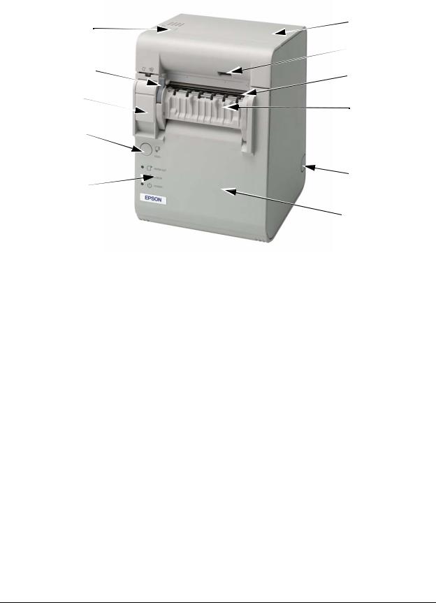
1.2.1 Part Names (TM-L90)
power switch |
cutter cover |
|
 manual cutter
roll paper cover
open lever
Perforation to pass
the cables through
 roll paper cover
 control panel
FEED Button
Printer Part Names
*Refer to page 2-19 for the location of the DIP switches.
*Another FEED button is located under the roll paper cover. Refer to page 2-23 for the location.
Rev. B |
Product Overview 1-3 |
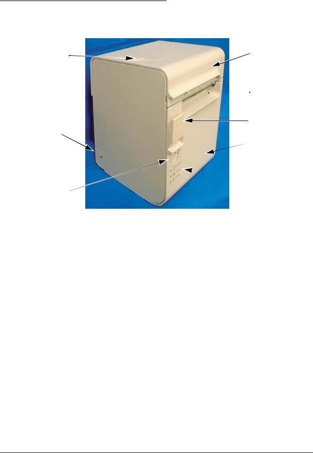
1.2.2 Part names (TM-L90 peeler specification)
 cutter cover
power switch
label peeling
sensor
peeler cover
open lever
 manual cutter
roll paper cover |
|
open lever |
peeler cover |
|
|
FEED Button |
|
|
wiring knockout |
control panel |
|
|
roll paper cover |
Part Names of TM-L90 Peeler Specification
*Refer to page 2-19 for the DIP switch positions.
*There is also a FEED button under the roll paper cover. Refer to page 2-23 for the position.
1-4 Product Overview |
Rev. B |

TM-L90/TM-L90 with Peeler Technical Reference Guide
1.2.3 Control Panel
 FEED Button
PAPER OUT LED
ERROR LED
POWER LED
FEED button (with TM-L90)
Pressing the FEED button feeds the roll paper.
The printer paper feed depends on the line feed amount set. However, in the following cases, FEED cannot be used for paper feed.
•When the roll paper cover is open
•When performing cleaning
•When performing self-testing (Press the FEED button to stop self-testing and press it again to resume it.)
•When the FEED button has a defined function in a macro definition command. (When using ESC/POS commands)
FEED button (with the TM-L90 peeler specification)
FEED has the following 3 functions.
•Feeding roll paper
•Initializing the mechanism
(After closing the roll paper cover, the status changes to waiting to print when FEED is pressed)
•Recovering from errors
Feeding roll paper
The printer paper feed depends on the line feed amount set. However, in the following cases, FEED cannot be used for paper feed.
•The roll paper runs out
•When the roll paper cover is open
•When waiting for label removal
•When waiting for FEED to be pressed
•When an error occurs
Rev. B |
Product Overview 1-5 |

Initializing the mechanism(with TM-L90)
You can initialize the mechanism (paper feed operation) with the following procedure.
1.Open the roll paper cover.
2.Close the roll paper cover.
3.Press FEED.
•If the roll paper is inserted after the roll paper cover is opened and closed, the printer waits for FEED to be pressed, and then the PAPER OUT LED flashes. In this case, press FEED.
•Caution: When memory switch 8-6 is set to "ON," If the roll paper is inserted when the power is off, or if the roll paper cover is opened and closed then the power is turned on, press FEED.
Recovering from errors
When error recovery with FEED is enabled by memory switch 8-1, pressing FEED when a paper layout error occurs recovers from the error and performs automatic paper layout.
Initializing the mechanism(with TM-L90 with Peeler)
You can initialize the mechanism (paper feed operation) with the following procedure.
1.Open the peeler cover.
2.Open the roll paper cover.
3.Close the peeler cover and the roll paper cover.
4.Press FEED.
•If the roll paper is inserted after the roll paper cover is opened and closed, the printer waits for FEED to be pressed, and then the PAPER OUT LED flashes. In this case, press FEED.
•Caution: When memory switch 8-6 is set to "ON," If the roll paper is inserted when the power is off, or if the roll paper cover is opened and closed then the power is turned on, press FEED.
Recovering from errors
When error recovery with FEED is enabled by memory switch 8-1, pressing FEED when a paper layout error occurs recovers from the error and performs automatic paper layout.
1-6 Product Overview |
Rev. B |
TM-L90/TM-L90 with Peeler Technical Reference Guide
PAPER OUT LED (with TM-L90)
Lights when there is no more roll paper or there is little remaining.
(Default setting. The LED condition varies according to the memory switch settings. Refer to “Starting the Memory Switch Setting mode” on page 2-23 and“Error code” on page F-3 for details.)
Off when there is a sufficient amount of roll paper remaining.
(Default setting. The LED condition varies according to the memory switch settings. Refer to “Starting the Memory Switch Setting mode” on page 2-23 and“Error code” on page F-3 for details.)
Flashes when a self test is in progress or when the printer waits for the macro execution switch to go on.
PAPER OUT LED (with the TM-L90 peeler specification)
Lights when there is no more roll paper or there is little remaining.
(Default setting. The LED condition varies according to the memory switch settings. Refer to “Starting the Memory Switch Setting mode” on page 2-23 and“Error code” on page F-3 for details.)
Off when there is a sufficient amount of roll paper remaining.
(Default setting. The LED condition varies according to the memory switch settings. Refer to “Starting the Memory Switch Setting mode” on page 2-23 and“Error code” on page F-3 for details.)
Flashes when a self test is in progress or when the printer waits for the macro execution switch to go on.
When the roll paper is inserted and the roll paper cover is closed, one label is ejected and the LED starts flashing. It flashes until FEED is pressed.
When a label is issued, flashing starts after it is issued. The LED flashes until the label is removed from the peeler.
POWER LED
Lights when the power supply is on.
Off when the power supply is turned off.
Flashes during execution of each operation.
ERROR LED
Lights when the printer is offline.
Off under normal conditions.
Flashes when an error occurs. (Refer to “Error code” on page F-3 for details)
1.2.4Power Switch
Refer to “Printer Part Names” on page 1-3 for the power switch location.
Turn on the power by holding down the POWER button 1 second or longer. Turn off the power by holding down the POWER button 3 seconds or longer.
Rev. B |
Product Overview 1-7 |

The printer is normally turned on/off with this switch. You can select whether to enable or disable the power switch using the DIP switches.
When the DIP switches are set to OFF (power switch enabled), the power switch controls the TM printer as follows.
When the TM is turned off:
The TM is powered ON when the power supply switch is pressed more than 1 second.
When the TM is turned on:
The TM is powered OFF when the power supply switch is pressed more than 3 seconds. If for some reason pressing the power switch even more than 10 seconds does not turn the power off, the TM executes a forced power off.
 Note:
Note:
When the DIP switches are set to ON (power switch disabled), use direct control of the printer with ESC/ POS commands. (For details, refer to “TM Printer Operation Performed When Power Supply Switch is Disabled” on page 5-1.) The printer may not operate normally when using OPOS or the Advanced Printer Driver with the DIP switches set to ON.
 Note:
Note:
When using OPOS or the Advanced Printer Driver, do not set the DIP switches to ON (power switch disabled). The printer may not operate normally if the DIP switches are set to ON.
 Note:
Note:
Make sure to check whether the AC adapter is connected to the power supply before turning on the power switch of the printer.
1.2.5 Power switch cover
To prevent unintentional contact or improper changes and to improve the appearance, use a cover. When using the power switch cover, to reset the TM printer, press the power switch through the hole in the power switch cover.
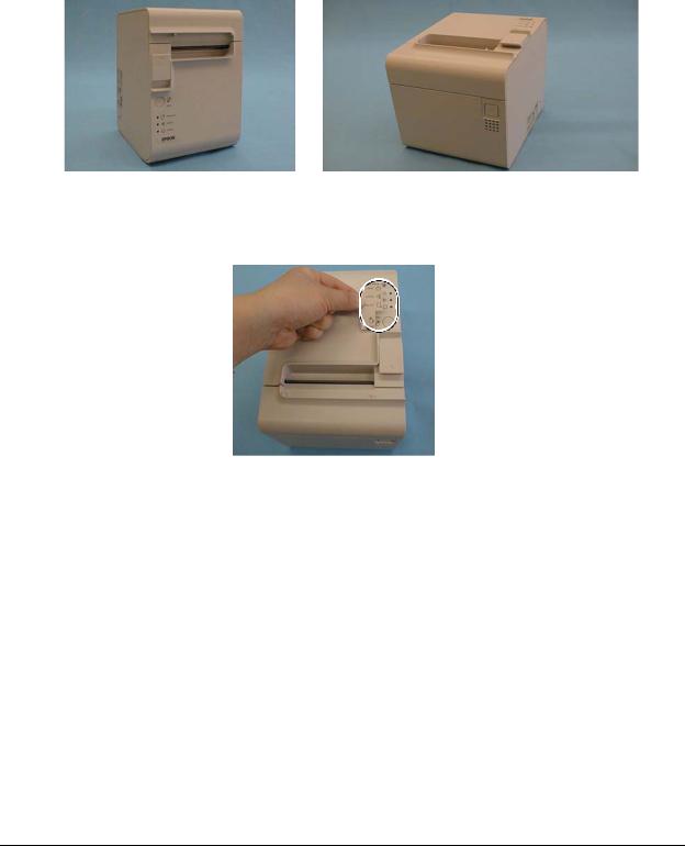
1.2.6 Mode switch (TM-L90 peeler specification only)
With the TM-L90 peeler specification, you can select the peeling issuing mode and continuous issuing mode with the mode switch. The mode switch switches between the peeling issuing mode and continuous issuing mode.
The mode switch is inside the top left of the printer when the roll paper cover is opened.
 Note:
Note:
Be sure that the peeler cover and the roll paper cover are open when switching the modes. The setting is effective when the power is turned on or the covers are closed. If the mode is switched with the covers closed, the setting will not be changed.
Be sure not to use a ball point pen to switch the modes. A ball point pen can damage the switch.
1-8 Product Overview |
Rev. B |

TM-L90/TM-L90 with Peeler Technical Reference Guide
mode switch
To use the peeling issuing mode, move the mode switch to the right.
To use the continuous issuing mode, move the mode switch to the left.
Rev. B |
Product Overview 1-9 |
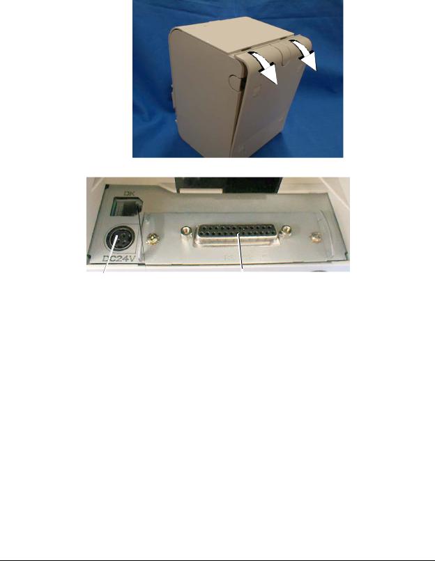
1.2.7 Connectors
Remove the bottom of the cover as shown in the illustration below. All cables are connected to the connector panel located on the lower rear side of the printer.
power |
drawer kick-out |
interface |
Connector Panel
 Note:
Note:
The model pictured is a serial interface model. For other information on interfaces and connectors, refer to “Connecting the Cable” (Chapter 3)
1-10 Product Overview |
Rev. B |

TM-L90/TM-L90 with Peeler Technical Reference Guide
Chapter 2
Setup
2.1 Setup Flow
Before using the printer, you need to set various settings to increase the printer's functionality. Configure the printer appropriately depending on the environment.
Determine how to install the printer (install it vertically or horizontally)
↓
Set the Roll Paper Near-End Detector
↓
Connect the power supply
↓
Autocutter settings (TM-L90 only)
↓
Set the Roll Paper width
↓
DIP switch settings
↓
Memory switch settings
↓
Set the Paper layout
Rev. B |
Setup 2-1 |

2.2 Installation Procedures
2.2.1Precaution For Installation
TM-L90
•Locate the printer on a flat surface, whichever orientation you choose.
•Avoid locations susceptible to dust and other foreign matter.
•Make sure to avoid bumping or otherwise exposing the printer to strong impact during operation.
•Avoid resting the printer on the power supply or other cables or other objects.
•Consider vibration during paper cutting and drawer usage. Take measures to prevent the printer from moving.
TM-L90 peeler specification
•Locate the printer on a flat surface, whichever orientation you choose.
•Avoid locations susceptible to dust and other foreign matter.
•Make sure to avoid bumping or otherwise exposing the printer to strong impact during operation.
•Avoid resting the printer on the power supply or other cables or other objects.
•Consider vibration during paper cutting and drawer usage. Take measures to prevent the printer from moving.
•To prevent malfunction of the label peeling sensor, do not locate the printer in direct sunlight.
2-2 Setup |
Rev. B |
TM-L90/TM-L90 with Peeler Technical Reference Guide
2.2.2 Instructions for Installation
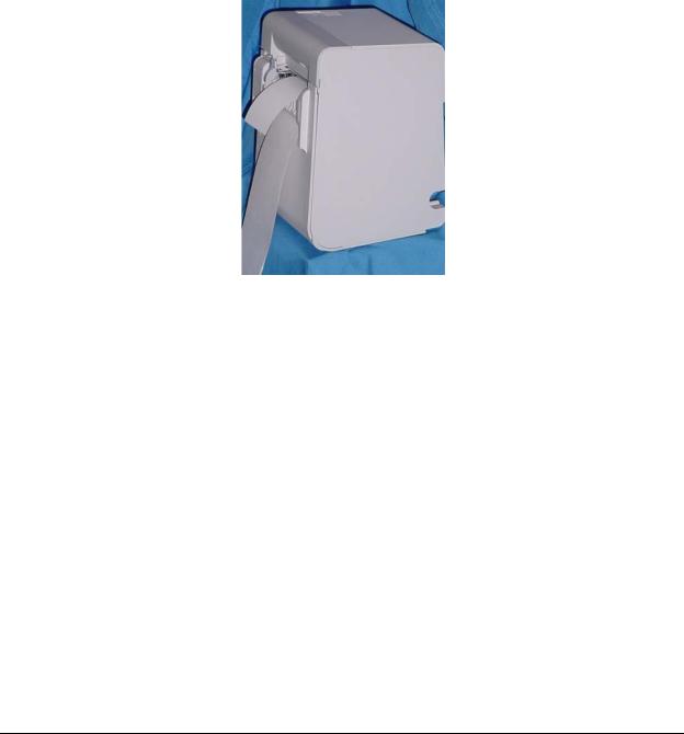
The TM-L90 can be placed vertically (paper outlet in front), horizontally (paper outlet at the top), or attached to a wall (using the optional wall hanging set WH-10).
With the TM-L90 with peeler, you can use it vertically or wall mounted with either peeling issuing or with continuous issuing (not using the peeler).
 Note:
Note:
For the TM-L90 with Peeler, horizontal installation is prohibited to avoid jams caused by re-sticking of backing paper and a label.
The illustration below shows the vertical installation for the TM-L90 with Peeler.
 Note:
Note:
To hang the printer on the wall, see the Wall Hanging Bracket Set Installation Manual provided with the WH-10 for instructions.
It is recommended to take some measures so that the printer will be stable when paper is being loaded or a drawer is being used. The DF-10 (velcro fastening) for fixing the printer is provided as an option.
When using the printer with the peeling issuing mode, be sure to install the printer so that a peeled label will not contact the used backing paper. Re-sticking of a peeled label to the backing paper will cause jams.
Rev. B |
Setup 2-3 |
For the TM-L90, when changing the way of installation, you need to adjust the following items:
•Control panel label used for horizontal installation
•The location of the Roll Paper Near-End Detector
The following figure shows the TM-L90 placed both vertically and horizontally.
When you install the printer horizontally, attach the control panel label as shown in the illustration below.
 Control panel label
 Note:
Note:
To hang the printer on the wall, see the Wall Hanging Bracket Set Installation Manual provided with the WH-10 for instructions.
When you use TM-L90 horizontally, peel off the backing sheet of the paper exit guide and attach it as shown below to prevent cut paper from falling inside the printer after paper is cut by the autocutter.
2-4 Setup |
Rev. B |

TM-L90/TM-L90 with Peeler Technical Reference Guide
 CAUTION:
When using the paper exit guide, do not use roll paper with a core that is smaller than the specification (inside diameter: 25.4 mm, outside diameter: 31.4 mm). Using a smaller one may cause a paper jam at the attached paper exit guide.
paper exit guide
Rev. B |
Setup 2-5 |

2.3 Adjusting Roll Paper Near-End Detection Position
2.3.1 With TM-L90
Below are three situations when roll paper N.E. detector adjustment is required.
When changing the way of installation. (Vertically Horizontally)
To adjust the location of detection to suit the diameter of the roll paper core used.
To adjust the amount of remaining paper desired.
 Note:
Note:
Roll paper centers are manufactured according to various specifications, making it impossible to exactly detect the remaining amount of paper.
N.E. detector holder
Detector adjustment screw
N.E. detector window when installing vertically
N.E. detector (location when installing horizontally)
Part names and the locations of N.E. detector components
1.Open the roll paper cover.
2.Remove the roll paper.
2-6 Setup |
Rev. B |
Loading...