


 Loading...
DOT MATRIX PRINTER
LC4511
LC4521
TECHNICAL MANUAL
[ SECOND EDITION ]
NOTICE
∙All rights reserved. Reproduction of any part of this manual in any form whatsoever, without STAR’s express permission is forbidden.
∙The contents of this manual are subject to change without notice.
∙All efforts have been made to ensure the accuracy of the contents of this manual at the time of going to press. However, should any errors be detected, STAR would greatly appreciate being informed of them.
∙The above notwithstanding, STAR can assume no responsibility for any errors in this manual.
©Copyright 1996 Star Micronics Co.,Ltd.

INTRODUCTION
This manual describes the LC-4511,4521 dot matrix printer.
It is designed for use as a reference for periodic inspections and maintenance procedures to be executed by service personnel. It is not intended for the general user. Users of this manual should have a basic knowledge and understanding of the English language.
∙ This manual is divided into the following sections:
Chapter 1 |
|
General Specifications |
Chapter 2 |
|
Theory of Operation |
Chapter 3 |
|
Adjustments |
Chapter 4 |
|
Parts Replacement |
Chapter 5 |
|
Maintenance and Lubrication |
Chapter 6 |
|
Troubleshooting |
Chapter 7 |
|
Parts List |
∙ First edition |
: |
Mar. 1996 |
Second edition |
: |
Aug. 1997 |
1
2
3
4
5
6
7
CHAPTER 1 |
1 |
|
GENERAL SPECIFICATIONS |
||
|
||
|
|
1. |
General Specifications.......................................................................................... |
3 |
|
2. |
External Appearance and Composition .............................................................. |
6 |
|
3. |
Control Panel ......................................................................................................... |
8 |
|
|
3-1. |
Switch Combination Functions ............................................................................. |
8 |
|
3-2. |
EDS Mode Settings ................................................................................................. |
9 |
4. |
Parallel Interface.................................................................................................. |
10 |
|
|
4-1. |
General Specifications ......................................................................................... |
10 |
|
4-2. |
Connector Signals ................................................................................................ |
10 |
5. |
Serial Interface (optional) ................................................................................... |
11 |
|
|
5-1. |
General Specifications ......................................................................................... |
11 |
|
5-2. Connector Signal and Functional Descriptions (SPC-8K, IS-8H192) ............... |
12 |
|
|
5-3. DIP Switch Settings (SPC-8K, IS-8H192) ............................................................ |
12 |
|
6. |
EE-PROM mode ................................................................................................... |
13 |
|
|
6-1. |
Outline ................................................................................................................... |
13 |
|
6-2. Explanation of special control codes ................................................................. |
13 |
|
|
6-3. |
EE-PROM MAP ...................................................................................................... |
14 |
|
6-4. |
Rewriting the EE-PROM ....................................................................................... |
17 |

GENERAL SPECIFICATIONS
1.General Specifications
Printing System |
Serial Impact Dot-Matrix |
|
|
|
|
Printing Speed |
Pitch |
|
Draft (cps/dpi) |
LQ (cps/dpi) |
|
|
|
|
|
|
|
LC-4521 |
Pica (10 cpi) |
|
300/120H (Normal) |
100/360H |
|
|
|
400/80H (HS) |
|||
|
|
|
|
|
|
|
Elite (12 cpi) |
|
360/120H |
120/360H |
|
|
Semi-condensed(15 cpi(S)) |
450/120H |
150/360H |
||
|
Semi-condensed(15 cpi(I)) |
225/240H |
150/360H |
||
|
Condensed pica (17 cpi) |
255/240H |
170/360H |
||
|
Condensed elite (20 cpi) |
300/240H |
198/360H |
||
|
24cpi (I) |
|
360/240H |
238/360H |
|
|
|
|
|
|
|
LC-4511 |
Pica (10 cpi) |
|
225/120H |
75/360H |
|
|
Elite (12 cpi) |
|
270/120H |
90/360H |
|
|
Semi-condensed(15 cpi(S)) |
337/120H |
112/360H |
||
|
Semi-condensed(15 cpi(I)) |
168/240H |
1112/360H |
||
|
Condensed pica (17 cpi) |
191/240H |
127/360H |
||
|
Condensed elite (20 cpi) |
225/240H |
149/360H |
||
|
24cpi (I) |
|
270/240H |
178/360H |
|
|
|
|
|
|
|
|
H: half-dot |
|
|
|
|
|
(S) : Standard mode only |
|
|
|
|
|
(I) : IBM mode only |
|
|
|
|
Print Direction |
Draft: |
Bi-directional logic seeking |
|
|
|
|
LQ: |
Bi-directional logic seeking |
|
|
|
|
Bit-Image: |
Uni-directional/ bi-directional logic seeking (selectable) |
|||
Print Head |
Number of pins: |
24 |
|
|
|
|
Life: |
200 million dots/pin (Normal Mode) |
|||
|
|
100 million dots/pin (Multi-Part Mode) |
|||
Line Spacing |
1/6”, 1/8”,7/60”,n/180”,n/360” |
|
|
|
|
|
7/72”, n/72”, n/216” : software |
|
|
||
Character Matrix |
Pitch |
|
Draft |
|
LQ |
|
|
|
|
|
|
LC-4521 |
Pica (10 cpi) |
|
24 × 9H (Normal) |
24 |
× 31H |
|
|
24 × 7H (HS) |
|||
|
|
|
|
|
|
|
Elite (12 cpi) |
|
24 × 9H |
24 |
× 27H |
|
Semi-condensed(15 cpi(S)) |
16 × 7H |
16 |
× 21H |
|
|
Semi-condensed(15 cpi(I)) |
24 × 9H |
24 |
× 16H |
|
|
Condensed pica (17 cpi) |
24 × 9H |
24 |
× 16H |
|
|
Condensed pica (20 cpi) |
24 × 9H |
24 |
× 16H |
|
|
24cpi (I) |
|
24 × 9H |
24 |
× 14H |
|
|
|
|
|
|
LC-4511 |
Pica (10 cpi) |
|
24 × 9H |
24 |
× 31H |
|
Elite (12 cpi) |
|
24 × 9H |
24 |
× 27H |
|
Semi-condensed(15 cpi(S)) |
16 × 7H |
16 |
× 21H |
|
|
Semi-condensed(15 cpi(I)) |
24 × 9H |
24 |
× 16H |
|
|
Condensed pica (17 cpi) |
24 × 9H |
24 |
× 16H |
|
|
Condensed elite (20 cpi) |
24 × 9H |
24 |
× 16H |
|
|
24cpi (I) |
|
24 × 9H |
24 |
× 14H |
|
|
|
|
|
|
– 3 –

GENERAL SPECIFICATIONS
|
H: half-dot |
|
|
(S) : Standard mode only |
|
|
(I) : IBM mode only |
|
Environment |
Operating temperature: 41°F to 95°F (5°C to 35°C) |
|
|
Storage temperature: |
–22°F to 149°F (–30°C to 65°C) |
|
Operating humidity: |
30% to 80% (non-condensing) |
|
Storage humidity: |
20% to 90% (non-condensing) |
Paper |
Cut-sheet (manual feeding) |
|
|
|
|
|
Paper width: |
7” to 16.54” / 178 to 420 mm |
|
Paper length: |
5.5” to 14” / 140 to 356 mm |
|
Paper thickness: |
0.00276” to 0.00472” / 0.07 to 0.12 mm |
|
Paper weight: |
14 to 24 lbs. / 52 to 90 g/m2 / 45 to 77 kg |
|
Cut-sheet (with optional automatic sheet feeder) |
|
|
|
|
|
Paper size: |
B5, A4, LT, B4, A3, Legal |
|
Paper thickness: |
0.00315” to 0.00472” / 0.08 to 0.12 mm |
|
Paper weight: |
16 to 24 lbs. / 60 to 90 g/m2 / 52 to 77 kg |
|
Hopper: |
50 sheets of 64 g/m2 |
|
|
30 sheets of 80 g/m2 |
|
Stacker: |
10 sheets |
|
Fanfold (with push tractor feeder) |
|
|
|
|
|
Paper width: |
4” to 16.5” / 101.6 to 419 mm |
|
Paper thickness: |
0.00276” to 0.00433” / 0.07 to 0.11 mm (one-ply) |
|
|
0.01378” / 0.35 mm maximum (total thickness of multi-ply |
|
|
paper, non-carbon) |
|
Paper weight: |
14 to 22 lbs. / 52 to 82 g/m2 / 45 to 70 kg (one-ply) |
|
|
11 to 14 lbs. / 40 to 52 g/m2 / 34 to 45 kg (multi-ply) |
|
Copies: |
Original + 1 or 2 (Normal Mode) |
|
|
Original + 3 or 4 (Multi-Part Mode) |
|
|
* Multi-Part Mode is recommended when using optional |
|
|
pull tractor unit. |
|
Fanfold (with optional pull tractor feeder) |
|
|
|
|
|
Paper width: |
4” to 16.0” / 101.6 to 406 mm |
|
Paper thickness: |
0.00276” to 0.00433” / 0.07 to 0.11 mm (one-ply) |
|
|
0.01378” / 0.35 mm maximum (total thickness of multi-ply |
|
|
paper, non-carbon) |
|
Paper weight: |
14 to 22 lbs. / 52 to 82 g/m2 / 45 to 70 kg (one-ply) |
|
|
11 to 14 lbs. / 40 to 52 g/m2 / 34 to 45 kg (multi-ply) |
|
Copies: |
Original + 1 or 2 (Normal Mode) |
|
|
Original + 3 or 4 (Multi-Part Mode) |
|
Labels |
|
|
|
|
|
Backing sheet: |
4.5” to 16.5” / 114 to 419 mm |
|
Thickness |
|
|
Backing sheet: |
0.00268” to 0.0035” / 0.07 to 0.09mm |
|
Total: |
0.0075” / 0.19mm max. |
– 4 –

|
|
GENERAL SPECIFICATIONS |
Emulation |
Standard Mode: |
EPSON ESC/P (24-pin) |
|
|
NEC Graphic compatible |
|
IBM Mode: |
Proprinter XL24E |
Interface |
Standard: |
Centronics parallel |
|
Option: |
RS-232C/RS-422 serial |
Ribbon Type |
On-carriage, dedicated |
|
|
Monochrome (Y24WH), Black only |
|
Ribbon Life |
2.5 million characters (Draft 10 cpi) |
|
Power Supply |
120V AC +10%/–17%, 230V AC +14%/–13%; 50/60Hz |
|
|
(depending on country of purchase) |
|
Power Consumption |
|
|
|
LC-4521 14W during standby / 63W during ASCII draft printing |
|
|
LC-4511 9W during standby / 45W during ASCII draft printing |
|
Options |
PT-15HA Pull Tractor Unit |
|
|
SF-15HA Single-Bin Automatic Sheet Feeder |
|
|
IS-8H192 Serial Interface Unit |
|
|
IS-32H768 Serial Interface Unit |
|
|
SPC-8K Serial-To-Parallel Converter |
|
186mm |
7.3" |
|
|
590mm 23.2"
355mm.9" 13
Weight : 19.2lbs/8.7kg
Fig. 1-1 External dimensions
– 5 –

GENERAL SPECIFICATIONS
2.External Appearance and Composition
Paper guide
Front cover
Mute cover
Control panel |
Interface connector |
Fig. 1-2 Front view of the Printer
Release lever
Power switch
Platen knob
Fig. 1-3 Rear view of the Printer
– 6 –
GENERAL SPECIFICATIONS
Fig. 1-4 Front cover removed
Fig. 1-5 Diagram of internal layout
– 7 –

GENERAL SPECIFICATIONS
3.Control Panel
3-1. Switch Combination Functions
HS-DRAFT/DRAFT |
BANK |
SW |
10 CPI |
|
|
|
POWER |
|
|
|
|
12 CPI |
|
|
|
|
|
ROMAN |
A1 |
D4 |
15 CPI |
|
|
|
|
|
SANSERIF |
|
|
|
|
|
|
|
|
COURIER |
B2 |
E5 |
COND |
|
MICRO FEED |
|
|
|
PRESTIGE |
|
|
|
|
|
|
||
|
|
|
|
|
|
|
|
|
ORATOR |
C3 |
F6 |
PROP |
|
|
|
|
|
|
FONT |
|
PITCH |
SET/EJECT |
FORM FEED |
LINE FEED |
ON LINE |
|
|
|
PARK |
|
|||||
|
|
|
|
|
|
|
|
|
EDS |
BANK |
|
SWITCH |
STATUS |
ON/OFF |
EXIT |
|
|
|
Font Selection |
|
Pitch Selection |
Set/Eject/Park |
Form Feed |
Line Feed |
On-Line |
|
|
Panel Macro |
|
Back ward |
Forward |
Micro Feed |
|
||
|
Set TOF |
|
|
Auto Loading Position Change Mode |
|
|||
|
Buffer Clear & All Reset |
|
|
|
|
OFF-LINE |
||
|
|
|
|
|
|
|
|
|
|
|
|
|
Quiet Mode |
Tear off (Long) |
Tear off (Short) |
Off-Line |
ON-LINE |
|
|
|
|
|
|
|
|
|
|
Font Lock |
|
Pitch Lock |
Multi-part Mode |
Hex Dump Mode |
Long Test |
Short Test |
|
|
Font & Pitch Lock |
|
|
|
|
|
||
|
|
|
|
|
|
EDS Mode |
|
|
|
|
|
|
|
|
Dot-Adjustment Mode |
|
|
|
|
|
|
Aging Mode |
|
|
|
|
|
|
|
|
Dot-Adjustment Print Mode |
|
|
|
|
|
|
|
|
|
EE-PROM Data Initialize |
|
POWER-ON |
|
|
|
|
|
|
|
|
|
|
|
Bank |
|
Switch |
Status |
On/Off |
Exit |
|
|
|
|
|
|
|
|
|
|
EDS MODE |
|
Left |
|
Right |
Next |
|
|
Exit |
DOT-ADJUSTMENT MODE |
|
|
|
|
|
|
|
|
|
|
|
|
|
Paper Loading |
Back ward |
Forward |
Cancel |
|
|
|
|
|
|
|
Set |
|
|
Save
Factory settings
AUTO LOADING POSITION CHANGE MODE
– 8 –

GENERAL SPECIFICATIONS
3-2. EDS Mode Settings
Bank |
Switch |
|
|
|
Function |
|
|
|
ON |
|
|
|
OFF |
|
||
A |
1 |
|
Emulation |
|
|
|
|
|
STANDARD / EPSON |
|
|
IBM |
|
|
|
|
|
2 |
|
Character Table (CT) Standard / EPSON mode |
|
Graphics |
|
|
Italics |
|
|
|
|||||
|
|
|
|
|
IBM mode |
|
|
|
IBM #2 |
|
|
IBM #1 |
|
|
||
|
3 |
|
RAM Usage |
|
|
|
|
|
Input Buffer |
|
|
Download Buffer |
|
|||
|
4 |
|
Auto Sheet Feeder |
|
|
|
|
Not installed |
|
|
Installed |
|
|
|||
|
5 |
|
Paper Out |
|
|
|
|
|
Enabled |
|
|
Disabled |
|
|
||
|
6 |
|
Multi-Part Mode |
|
|
|
|
Disabled |
|
|
Enabled |
|
|
|||
B |
1 |
|
Graphics Direction |
|
|
|
|
Bi-directional |
|
|
Uni-directional |
|
||||
|
2 |
|
Tear-off |
|
|
|
|
|
Disabled |
|
|
Enabled |
|
|
||
|
3 |
|
Line Spacing |
|
|
|
|
|
1/6" |
|
|
1/8" |
|
|
|
|
|
4 |
|
Auto LF with CR |
|
|
|
|
Disabled |
|
|
Enabled |
|
|
|||
|
5 |
|
Zero Style |
|
|
|
|
|
Normal |
|
|
Slashed |
|
|
||
|
6 |
|
Strobe Timing |
|
|
|
|
|
Normal |
|
|
Reverse |
|
|
||
C |
1, 2 |
|
Print Mode |
|
|
|
|
|
|
|
|
|
|
|
|
|
|
|
|
LQ |
|
|
|
ON |
ON |
|
|
|
|
|
|
|
|
|
|
|
Draft |
|
|
|
OFF |
ON |
|
|
|
|
|
|
|
|
|
|
|
HS-Draft |
|
|
|
ON |
OFF |
|
|
|
|
|
|
||
|
|
|
|
|
|
|
|
|
|
|
|
|
|
|
|
|
|
3,4,5 |
|
Print Pitch |
|
|
|
|
|
|
|
|
|
|
|
|
|
|
|
|
10cpi |
|
|
ON |
ON |
ON |
Proportional |
|
|
|
OFF |
ON |
OFF |
|
|
|
|
12cpi |
|
|
OFF |
ON |
ON |
|
|
|
|
|
|
|
|
|
|
|
15cpi |
|
|
ON |
OFF |
ON |
|
|
|
|
|
|
|
|
|
|
|
17cpi |
|
|
OFF |
OFF |
ON |
|
|
|
|
|
|
|
|
|
|
|
20cpi |
|
|
ON |
ON |
OFF |
|
|
|
|
|
|
||
|
6 |
|
Quiet |
|
|
|
|
|
Disabled |
|
|
Enabled |
|
|
||
D |
1,2,3,4 |
|
Page Length |
|
|
|
|
|
|
|
|
|
|
|
|
|
|
|
|
11"/Letter |
|
ON |
ON |
ON |
ON |
14"/Legal |
|
|
OFF |
ON |
OFF |
ON |
|
|
|
8" |
|
|
OFF |
ON |
ON |
ON |
10.5"/Executive |
|
|
ON |
OFF |
OFF |
ON |
|
|
|
|
11.7"/A4 |
|
ON |
OFF |
ON |
ON |
7.25"/Executive |
|
|
OFF |
OFF |
OFF |
ON |
|
|
|
12" |
|
|
OFF |
OFF |
ON |
ON |
3.5" |
|
|
ON |
ON |
ON |
OFF |
|
|
|
|
8.5"/Letter |
|
ON |
ON |
OFF |
ON |
5.5" |
|
|
OFF |
ON |
ON |
OFF |
|
|
5 |
|
CR Centering Position |
|
|
|
|
Long |
|
|
Short |
|
|
|
||
|
|
|
|
|
|
|
|
|
|
|
|
|
||||
E |
1,2,3,4,5 |
|
IBM Code Page (CT=Graphics, IBM #1, #2) |
|
|
|
|
|
|
|
|
|||||
|
|
#437 |
|
ON |
ON |
ON |
ON |
ON |
#3844 |
ON |
OFF |
ON |
OFF |
ON |
||
|
|
#850 |
|
OFF |
ON |
ON |
ON |
ON |
#3845 |
OFF |
OFF |
ON |
OFF |
ON |
||
|
|
#860 |
|
ON |
OFF |
ON |
ON |
ON |
#3846 |
ON |
ON |
OFF |
OFF |
ON |
||
|
|
#861 |
|
OFF |
OFF |
ON |
ON |
ON |
#3847 |
OFF |
ON |
OFF |
OFF |
ON |
||
|
|
#863 |
|
ON |
ON |
OFF |
ON |
ON |
#3848 |
ON |
OFF |
OFF |
OFF |
ON |
||
|
|
#865 |
|
OFF |
ON |
OFF |
ON |
ON |
#852 |
OFF |
OFF |
OFF |
OFF |
ON |
||
|
|
#866 |
|
ON |
OFF |
OFF |
ON |
ON |
#737 |
ON |
ON |
ON |
ON |
OFF |
||
|
|
#3840 |
OFF |
OFF |
OFF |
ON |
ON |
#851 |
OFF |
ON |
ON |
ON |
OFF |
|||
|
|
#3841 |
ON |
ON |
ON |
OFF |
ON |
#869 |
ON |
OFF |
ON |
ON |
OFF |
|||
|
|
#3843 |
OFF |
ON |
ON |
OFF |
ON |
#928 |
OFF |
OFF |
ON |
ON |
OFF |
|||
|
|
|
International Character Set (CT=Italics) |
|
|
|
|
|
|
|
|
|
||||
|
|
|
U.S.A. |
ON |
ON |
ON |
ON |
ON |
Japan |
ON |
ON |
ON |
OFF |
ON |
||
|
|
|
France |
OFF |
ON |
ON |
ON |
ON |
Norway |
OFF |
ON |
ON |
OFF |
ON |
||
|
|
|
Germany |
ON |
OFF |
ON |
ON |
ON |
Denmark-2 |
ON |
OFF |
ON |
OFF |
ON |
||
|
|
|
England |
OFF |
OFF |
ON |
ON |
ON |
Spain-2 |
OFF |
OFF |
ON |
OFF |
ON |
||
|
|
|
Denmark-1 |
ON |
ON |
OFF |
ON |
ON |
Latin America |
ON |
ON |
OFF |
OFF |
ON |
||
|
|
|
Sweden |
OFF |
ON |
OFF |
ON |
ON |
Korea |
OFF |
ON |
OFF |
OFF |
ON |
||
|
|
|
Italy |
ON |
OFF |
OFF |
ON |
ON |
Ireland |
ON |
OFF |
OFF |
OFF |
ON |
||
|
|
|
Spain-1 |
OFF |
OFF |
OFF |
ON |
ON |
Legal |
OFF |
OFF |
OFF |
OFF |
ON |
||
F |
1, 2, 3, 4, 5 |
|
NLQ Font Selection |
|
|
|
|
|
|
|
|
|
|
|
||
|
|
|
Roman |
ON |
ON |
ON |
ON |
ON |
|
|
|
|
|
|
|
|
|
|
|
Sanserif |
OFF |
ON |
ON |
ON |
ON |
|
|
|
|
|
|
|
|
|
|
|
Courier |
ON |
OFF |
ON |
ON |
ON |
|
|
|
|
|
|
|
|
|
|
|
Prestige |
OFF |
OFF |
ON |
ON |
ON |
|
|
|
|
|
|
|
|
|
|
|
Orator |
OFF |
OFF |
OFF |
ON |
ON |
|
|
|
|
|
|
|
|
|
|
|
Option |
|
|
|
|
|
|
|
|
|
|
|
|
|
|
|
|
|
|
|
|
|
|
|
|
|
|
|
|
|
|
|
|
|
Script |
ON |
ON |
OFF |
ON |
ON |
Cinema |
ON |
OFF |
OFF |
OFF |
ON |
||
|
|
|
OCR-B |
OFF |
ON |
OFF |
ON |
ON |
Code 39 |
OFF |
OFF |
OFF |
OFF |
ON |
||
|
|
|
OCR-A |
ON |
OFF |
OFF |
ON |
ON |
UPC/EAN |
ON |
ON |
ON |
ON |
OFF |
||
|
|
|
Orator-2 |
ON |
ON |
ON |
OFF |
ON |
Old-Stile |
OFF |
ON |
ON |
ON |
OFF |
||
|
|
|
TW-Light |
OFF |
ON |
ON |
OFF |
ON |
Firenze |
ON |
OFF |
ON |
ON |
OFF |
||
|
|
|
L-Gothic |
ON |
OFF |
ON |
OFF |
ON |
Arabic Naskh |
OFF |
OFF |
ON |
ON |
OFF |
||
|
|
|
Blippo |
OFF |
OFF |
ON |
OFF |
ON |
Arabic Koufi |
ON |
ON |
OFF |
ON |
OFF |
||
|
|
|
H-Gothic |
ON |
ON |
OFF |
OFF |
ON |
Arabic Naskh-Eilani OFF |
ON |
OFF |
ON |
OFF |
|||
|
|
|
Orane |
OFF |
ON |
OFF |
OFF |
ON |
|
|
|
|
|
|
|
|
|
|
|
|
|
|
|
|
|
|
|
|
|
|
|
|
|
– 9 –

GENERAL SPECIFICATIONS
4. |
Parallel Interface |
|
|
|
|
|
4-1. |
General Specifications |
|
|
|
|
|
|
|
|
|
|
||
|
Item |
|
|
Specifications |
||
|
|
|
|
|
|
|
|
Interface |
Centronics-compatible |
||||
|
|
|
|
|
|
|
|
Synchronization System |
Via externally supplied |
|
pulse |
||
|
STROBE |
|||||
|
|
|
|
|
|
|
|
I/F Protocol |
Using |
|
and BUSY signals |
||
|
ACK |
|||||
|
Logic Level |
Compatible with TTL level |
||||
|
|
|
|
|
|
|
ACK
Data
STROBE (EDS B-6 : ON)
STROBE (EDS B-6 : OFF)
BUSY
4-2. Connector Signals
5μs |
t |
t |
t |
t |
5μs |
|
|
|
|
|
t : More than 0.5μs |
|||
Fig. 1-6 Timing Charts for Parallel Interface
Pin |
|
|
|
|
|
Name |
Function |
|||||||
|
|
|
|
|
|
|
|
|
|
|
|
|
|
|
1 |
|
|
|
|
|
|
|
|
|
Goes low for ³ 0.5ms when active. |
||||
|
|
STROBE |
||||||||||||
2 |
|
|
|
DATA0 |
These signals represent information for the 1st through 8th bit of |
|||||||||
|
|
|
|
|
|
|
|
|
|
|
|
|
|
parallel data, respectively. Each signal is HIGH when data is logical 1, |
3 |
|
|
|
DATA1 |
||||||||||
|
|
|
|
|
|
|
|
|
|
|
|
|
|
and LOW when logical 0. |
4 |
|
|
|
DATA2 |
||||||||||
|
|
|
|
|
|
|
|
|
|
|
|
|
|
|
5 |
|
|
|
DATA3 |
|
|||||||||
|
|
|
|
|
|
|
|
|
|
|
|
|
|
|
6 |
|
|
|
DATA4 |
|
|||||||||
|
|
|
|
|
|
|
|
|
|
|
|
|
|
|
7 |
|
|
|
DATA5 |
|
|||||||||
|
|
|
|
|
|
|
|
|
|
|
|
|
|
|
8 |
|
|
|
DATA6 |
|
|||||||||
|
|
|
|
|
|
|
|
|
|
|
|
|
|
|
9 |
|
|
|
DATA7 |
|
|||||||||
|
|
|
|
|
|
|
|
|
|
|
|
|
|
|
10 |
|
|
|
|
|
|
|
|
|
|
10ms low to acknowledge receipt of data. |
|||
|
|
|
|
|
|
ACK |
||||||||
11 |
|
|
|
|
|
BUSY |
Printer sets line low when ready to receive data. |
|||||||
|
|
|
|
|
|
|
|
|
|
|
|
|
|
|
12 |
|
|
|
PAPER |
High when paper runs out. |
|||||||||
|
|
|
|
|
|
|
|
|
|
|
|
|
|
|
13 |
|
|
SELECT |
High when printer is on-line. |
||||||||||
|
|
|
|
|
|
|
|
|
|
|
|
|
|
|
14 |
|
|
|
|
|
|
|
|
Printer ignores this signal. |
|||||
|
|
|
|
|
AFXT |
|||||||||
15 |
|
|
|
|
|
|
|
|
|
|
|
|
|
Not used. |
|
|
|
|
|
|
|
|
|
|
|
|
|
|
|
16 |
SIGNAL GND |
Signal ground |
||||||||||||
|
|
|
|
|
|
|
|
|
|
|
|
|
|
|
17 |
|
CHASSIS |
Chassis ground (isolated from signal ground) |
|||||||||||
|
|
|
|
|
|
|
|
|
|
|
|
|
|
|
18 |
|
|
|
|
|
|
+5V |
+5V DC output from printer |
||||||
|
|
|
|
|
|
|
|
|
|
|
|
|
|
|
19~30 |
|
|
|
|
|
|
GND |
Twisted pair ground return |
||||||
|
|
|
|
|
|
|
|
|
|
|
|
|
|
|
31 |
|
|
|
|
|
|
|
|
|
|
|
|
|
Printer is reset when this signal goes low. |
|
|
|
|
RESET |
||||||||||
32 |
|
|
|
|
|
|
|
|
|
|
|
Low when printing cannot continue due to error. |
||
|
|
|
ERROR |
|||||||||||
33 |
|
EXT GND |
External ground |
|||||||||||
|
|
|
|
|
|
|
|
|
|
|
|
|
|
|
34~35 |
|
|
|
|
|
|
|
|
|
|
|
|
|
Not used |
|
|
|
|
|
|
|
|
|
|
|
||||
36 |
|
SELECT IN |
|
Printer ignores this signal. |
||||||||||
– 10 –

GENERAL SPECIFICATIONS
5.Serial Interface (optional)
When using the serial interface, the optional Serial-Parallel Converter must be connected to the printer.
5-1. General Specifications
(SPC-8K) |
|
Interface |
RS-232C-level |
Synchronization |
Asynchronous |
Baud rate |
150, 300, 600, 1200, 2400, 4800, 9600, 19200 BPS (selectable) |
Word length |
|
Start bit |
1 |
Data bits |
7 or 8 (selectable) |
Parity bit |
Odd, even, none (selectable) |
Stop bits |
One or more |
Signal polarity |
|
Mark |
Logical 1 (-3V to -15V) |
Space |
Logical 0 (+3V to +15V) |
Handshaking |
DTR, XON/XOFF, ETX/ACK |
Data buffer |
8 kbytes (standard) |
(IS-8H192) |
|
Interface |
RS-232C-level only |
Synchronization |
Asynchronous |
Baud rate |
150, 300, 600, 1200, 2400, 4800, 9600, 19200 BPS (selectable) |
Word length |
|
Start bit |
1 |
Data bits |
7 or 8 (selectable) |
Parity bit |
Odd, even, none (selectable) |
Stop bits |
One or more |
Signal polarity |
|
Mark |
Logical 1 (–3V to –15V) |
Space |
Logical 0 (+3V to +15V) |
Handshaking |
DTR, XON/XOFF, ETX/ACK |
Data buffer |
8 kbytes (standard) |
(IS-32H768) |
|
RS-232C Interface |
|
Synchronization |
Asynchronous |
Baud rate |
150, 300, 600, 1200, 2400, 4800, 9600, 19200 BPS (selectable) |
Word length |
|
Start bit |
1 |
Data bits |
7 or 8 (selectable) |
Parity bit |
Odd, even, none (selectable) |
Stop bits |
One or more |
Signal polarity |
|
Mark |
Logical 1 (–3V to –15V) |
Space |
Logical 0 (+3V to +15V) |
Handshaking |
DTR, XON/XOFF, ETX/ACK |
Data buffer |
32 kbytes (standard) |
RS-422A Interface |
|
Synchronization |
Asynchronous |
Baud rate |
150, 300, 600, 1200, 2400, 4800, 9600, 19200 , 38400, 76800 BPS (selectable) |
Word length |
|
Start bit |
1 |
Data bits |
7 or 8 (selectable) |
Parity bit |
Odd, even, none (selectable) |
Stop bits |
One or more |
Signal polarity |
|
Mark |
Logical 1 (A is –0.2 V or less than B) |
Space |
Logical 0 (A is +0.2 V or more than B) |
Handshaking |
DTR, XON/XOFF, ETX/ACK |
Data buffer |
32 kbytes (standard) |
– 11 –

GENERAL SPECIFICATIONS
5-2. Connector Signal and Functional Descriptions (SPC-8K, IS-8H192)
Pin No. |
Signal name |
Direction |
Function |
|
|
|
|
|
|
1 |
GND |
— |
Printer chassis ground. |
|
|
|
|
|
|
2 |
TXD |
OUT |
This pin carries data from the printer. |
|
|
|
|
|
|
3 |
RXD |
IN |
This pin carries data to the printer. |
|
|
|
|
|
|
4 |
RTS |
OUT |
Always space. |
|
|
|
|
|
|
5 |
CTS |
— |
This signal is space when the computer is ready to send data. |
|
The printer does not check this pin. |
||||
|
|
|
||
|
|
|
|
|
6 |
NC |
|
Unused. |
|
|
|
|
|
|
7 |
GND |
— |
Signal ground. |
|
|
|
|
|
|
8~10 |
NC |
|
Unused. |
|
|
|
|
|
|
11 |
RCH |
OUT |
The printer sets this signal to space when it is ready to receive data. |
|
This line carries the same signal as pin 20. |
||||
|
|
|
||
|
|
|
|
|
12~19 |
NC |
|
Unused. |
|
|
|
|
|
|
20 |
DTR |
OUT |
The printer sets this signal to space when it is ready to receive data. |
|
|
|
|
|
|
21~25 |
NC |
|
Unused. |
|
|
|
|
|
5-3. DIP Switch Settings (SPC-8K, IS-8H192)
Switch |
ON |
OFF |
|
|
|
|
|
1 |
8 data bits |
7 data bits |
|
|
|
|
|
2 |
No parity |
Parity checked |
|
|
|
|
|
3 |
Handshaking protocols – see table below |
||
|
|||
4 |
|||
|
|
||
|
|
|
|
5 |
Odd parity |
Even parity |
|
|
|
|
|
6 |
|
|
|
|
|
|
|
7 |
Data transfer rate – see table below |
||
|
|
|
|
8 |
|
|
|
|
|
|
|
All switches are set to ON before the printer leaves the factory.
Protocol |
Switch 3 |
Switch 4 |
|
|
|
DTR mode |
ON |
ON |
|
|
|
XON/XOFF mode |
ON |
OFF |
|
|
|
ETX/ACK mode |
OFF |
ON |
|
|
|
Baud rate |
Switch 6 |
Switch 7 |
Switch 8 |
|
|
|
|
150 |
OFF |
OFF |
OFF |
|
|
|
|
300 |
OFF |
OFF |
ON |
|
|
|
|
600 |
OFF |
ON |
OFF |
|
|
|
|
1200 |
OFF |
ON |
ON |
|
|
|
|
2400 |
ON |
OFF |
OFF |
|
|
|
|
4800 |
ON |
OFF |
ON |
|
|
|
|
9600 |
ON |
ON |
OFF |
|
|
|
|
19200 |
ON |
ON |
ON |
|
|
|
|
– 12 –

GENERAL SPECIFICATIONS
6. EE-PROM mode
6-1. Outline
These settings can be changed in the EE-PROM mode by writing data directly to the EE-PROM on the main logic board:
Setting EE-PROM mode
• Send <ESC><SUB>(09)H command.
Canceling EE-PROM mode
• Initialize the printer by sending <ESC>@
6-2. Explanation of special control codes
<ESC>@ |
Exits printer from EE-PROM mode and initializes the printer. |
<ESC>M@ |
Returns all data in the EE-PROM to the factory settings. After the buffer is cleared, the buzzer sounds. If |
|
the printer is powered off before the buzzer sounds, all data in the buffer is not cleared. |
|
If all data is not cleared from the buffer, operation is not guaranteed. Be sure to allow the buzzer |
|
to sound before you turn the printer off! |
<ESC>MWn
Code |
Function |
Address |
Capacity |
<ESC>MW0 <data> |
Stores data into entire area of EE-PROM. |
00H-7FH |
128bytes |
|
|
|
|
<ESC>MW1nm |
Stores data (m) into the address (n) |
nH |
1 byte |
|
|
|
|
<ESC>MW2<data> |
Stores auto-start software data into |
40H-5EH |
30bytes |
|
EE-PROM. |
5FH-7DH |
30bytes |
|
|
|
|
•The data (m) used in the commands above are stored in the specified address in order (n).
•When the data to be stored exceeds the specified capacity, subsequent data are ignored.
•Data are stored in the EE-PROM according to the memory map. (See section 3. EDS mode setting and 6-3. EE-PROM Map.)
•After all data are stored, a beep indicates the completion of storage.
•If the printer is powered off during data storage, data stored before power off are valid, but subsequent operation of the printer is not guaranteed.
Do not power off the printer while data is being stored!
<ESC>MR Dumps all data in the EE-PROM to a hard copy.
For an example of using these control codes, see section 6-4. For the corresponding EE-PROM addresses, see the EE-PROM memory map in section 3-2. EDS mode setting and 6-3 EE-PROM Map.
– 13 –

GENERAL SPECIFICATIONS
6-3. EE-PROM MAP
Address |
|
|
|
|
|
|
|
|
Function |
|
|
|
|
|
|
|
|
|
|
|
|
|
Factory data |
||||
|
|
|
|
|
|
|
|
|
|
|
|
|
|
|
|
|
|
|
|
|
|
|
|
|
|
|
|
00H |
EDS setting |
|
|
|
|
|
|
|
|
|
|
|
|
|
|
|
|
|
|
|
|
|
|
FFH |
|||
|
|
|
|
|
|
|
|
|
|
|
|
|
|
|
|
|
|
|
|
|
|
|
|
|
|
|
|
|
|
Bit |
Function |
|
|
|
|
|
|
|
|
|
1 |
|
|
|
|
0 |
|
|
|
|
|
|
|
||
|
|
|
|
|
|
|
|
|
|
|
|
|
|
|
|
|
|
|
|
|
|
|
|
|
|
|
|
|
|
b0 |
Emulation |
|
|
|
|
|
|
|
|
|
STANDARD/EPSON |
|
IBM |
|
|
|
|
|
|
|
|
||||
|
|
|
|
|
|
|
|
|
|
|
|
|
|
|
|
|
|
|
|
|
|
|
|
|
|
|
|
|
|
|
Character Table |
|
|
|
|
|
|
|
|
|
|
|
|
|
|
|
|
|
|
|
|||||
|
|
b1 |
Standard / EPSON mode |
Graphics |
|
Italics |
|
|
|
|
|
|
|
|
|||||||||||||
|
|
|
IBM mode |
|
|
|
|
|
|
|
|
|
|
|
|
|
|
|
|
|
|||||||
|
|
|
|
|
|
|
|
IBM #2 |
|
IBM #1 |
|
|
|
|
|
|
|
||||||||||
|
|
|
|
|
|
|
|
|
|
|
|
|
|
|
|
|
|
|
|
|
|
|
|
|
|
||
|
|
b2 |
RAM Usage |
|
|
|
|
|
|
|
|
|
Input Buffer |
|
Download Buffer |
|
|
|
|||||||||
|
|
b3 |
Auto Sheet Feeder |
|
|
|
|
|
Not installed |
|
Installed |
|
|
|
|
|
|
|
|||||||||
|
|
b4 |
Paper out Detector |
|
|
|
|
|
Enabled |
|
Disabled |
|
|
|
|
|
|
|
|||||||||
|
|
|
|
|
|
|
|
|
|
|
|
|
|
|
|
|
|
|
|
|
|
|
|
|
|
||
|
|
b5 |
Multi-Part Mode |
|
|
|
|
|
Disabled |
|
Enabled |
|
|
|
|
|
|
|
|||||||||
|
|
|
|
|
|
|
|
|
|
|
|
|
|
|
|
|
|
|
|
|
|
|
|
|
|
|
|
01H |
EDS setting |
|
|
|
|
|
|
|
|
|
|
|
|
|
|
|
|
|
|
|
|
|
|
FFH |
|||
|
|
|
|
|
|
|
|
|
|
|
|
|
|
|
|
|
|
|
|
|
|
|
|
|
|
|
|
|
|
Bit |
Function |
|
|
|
|
|
|
|
|
|
1 |
|
|
|
|
0 |
|
|
|
|
|
|
|
||
|
|
|
|
|
|
|
|
|
|
|
|
|
|
|
|
|
|
|
|
|
|
|
|
||||
|
|
b0 |
Graphics Direction |
|
|
|
|
Bi-directional |
|
Uni-directional |
|
|
|
||||||||||||||
|
|
b1 |
Tear-off |
|
|
|
|
|
|
|
|
|
Disabled |
|
Enabled |
|
|
|
|
|
|
|
|||||
|
|
|
|
|
|
|
|
|
|
|
|
|
|
|
|
|
|
|
|
|
|
|
|
|
|
|
|
|
|
b2 |
Line Spacing |
|
|
|
|
|
|
|
|
|
1/6" |
1/8" |
|
|
|
|
|
|
|
|
|
||||
|
|
b3 |
Auto LF with CR |
|
|
|
|
|
Disabled |
|
Enabled |
|
|
|
|
|
|
|
|||||||||
|
|
b4 |
Zero Style |
|
|
|
|
|
|
|
|
|
Normal |
|
Slashed |
|
|
|
|
|
|
|
|||||
|
|
|
|
|
|
|
|
|
|
|
|
|
|
|
|
|
|
|
|
|
|
|
|
|
|
||
|
|
b5 |
Strobe Timing |
|
|
|
|
|
Normal |
|
Reverse |
|
|
|
|
|
|
|
|||||||||
|
|
|
|
|
|
|
|
|
|
|
|
|
|
|
|
|
|
|
|
|
|
|
|
|
|
|
|
02H |
EDS setting |
|
|
|
|
|
|
|
|
|
|
Print Pitch |
|
|
|
|
|
|
FFH |
||||||||
|
|
|
|
|
|
|
|
|
|
|
|
|
|
|
|
|
|
|
|
|
|
||||||
|
|
|
|
|
|
|
|
|
|
|
|
|
|
|
|
|
|
|
|
|
|
|
|
|
|
|
|
|
|
|
Print Mode |
|
|
|
|
|
|
Function |
|
|
b2 |
|
b3 |
|
|
b4 |
|
|
|
||||||
|
|
Function |
|
b0 |
|
|
b1 |
|
|
|
|
|
10cpi |
|
1 |
|
1 |
|
|
1 |
|
|
|
||||
|
|
LQ |
|
|
1 |
|
|
1 |
|
|
|
|
|
12cpi |
|
0 |
|
1 |
|
|
1 |
|
|
|
|||
|
|
|
|
|
|
|
|
|
|
|
|
|
|
|
|
|
|
|
|
|
|
|
|
|
|
|
|
|
|
Draft |
|
0 |
|
|
1 |
|
|
|
|
|
15cpi |
|
1 |
|
0 |
|
|
1 |
|
|
|
||||
|
|
HS-Draft |
|
1 |
|
|
0 |
|
|
|
|
|
17cpi |
|
0 |
|
0 |
|
|
1 |
|
|
|
||||
|
|
|
|
|
|
|
|
|
|
|
|
|
|
|
20cpi |
|
1 |
|
1 |
|
|
0 |
|
|
|
||
|
|
|
|
|
|
|
|
|
|
|
|
|
|
|
|
|
|
|
|
|
|
|
|
|
|
|
|
|
|
|
|
|
|
|
|
|
|
|
|
|
|
|
Proportional |
|
0 |
|
1 |
|
|
0 |
|
|
|
||
|
|
|
|
|
|
|
|
|
|
|
|
|
|
|
|
|
|
|
|
|
|
|
|
|
|
|
|
|
|
|
|
|
|
|
|
|
|
|
|
|
|
|
|
|
|
|
|
|
|
|
|
|
|
||
|
|
Bit |
Function |
|
|
|
|
|
|
|
|
|
1 |
|
|
|
|
0 |
|
|
|
|
|
|
|
||
|
|
|
|
|
|
|
|
|
|
|
|
|
|
|
|
|
|
|
|
|
|
|
|
|
|
|
|
|
|
b5 |
Quiet |
|
|
|
|
|
|
|
|
|
Disabled |
|
|
Enabled |
|
|
|
|
|
|
|
||||
|
|
|
|
|
|
|
|
|
|
|
|
|
|
|
|
|
|
|
|
|
|
|
|
|
|
|
|
03H |
EDS setting |
|
|
|
|
|
|
|
|
|
|
|
|
|
|
|
|
|
|
|
|
|
|
FFH |
|||
|
|
|
|
|
|
|
|
|
|
|
Page Length |
|
|
|
|
|
|
|
|
|
|
|
|
||||
|
|
|
|
|
|
|
|
|
|
|
|
|
|
|
|
|
|
|
|
|
|
||||||
|
|
Function |
|
b0 |
|
b1 |
b2 |
b3 |
|
|
Function |
|
|
b0 |
|
b1 |
b2 |
|
b3 |
|
|
||||||
|
|
11"/Letter |
|
1 |
|
|
1 |
1 |
1 |
|
|
14"/Legal |
|
0 |
|
1 |
0 |
|
1 |
|
|
|
|||||
|
|
8" |
|
|
|
0 |
|
|
1 |
1 |
1 |
|
|
10.5"/Executive |
|
1 |
|
0 |
0 |
|
1 |
|
|
|
|||
|
|
11.7"/A4 |
|
1 |
|
|
0 |
1 |
1 |
|
|
7.25"/Executive |
|
0 |
|
0 |
0 |
|
1 |
|
|
|
|||||
|
|
12" |
|
|
|
0 |
|
|
0 |
1 |
1 |
|
|
3.5" |
|
1 |
|
1 |
1 |
|
0 |
|
|
|
|||
|
|
|
|
|
|
|
|
|
|
|
|
|
|
|
|
|
|
|
|
|
|
|
|||||
|
|
8.5"/Letter |
|
1 |
|
|
1 |
0 |
1 |
|
|
5.5" |
|
0 |
|
1 |
1 |
|
0 |
|
|
|
|||||
|
|
|
|
|
|
|
|
|
|
|
|
|
|
|
|
|
|
|
|
|
|
|
|
|
|
||
|
|
|
|
|
|
|
|
|
|
|
|
|
|
|
|
|
|
|
|
|
|
|
|
|
|
||
|
|
Bit |
Function |
|
|
|
|
|
|
|
|
|
1 |
|
|
|
|
0 |
|
|
|
|
|
|
|
||
|
|
|
|
|
|
|
|
|
|
|
|
|
|
|
|
|
|
|
|
|
|
|
|
|
|||
|
|
b4 |
CR Centering Position |
|
|
|
|
Long |
|
|
Short |
|
|
|
|
|
|
|
|||||||||
|
|
|
|
|
|
|
|
|
|
|
|
|
|
|
|
|
|
|
|
|
|
|
|
|
|
|
|
– 14 –

GENERAL SPECIFICATIONS
Address |
|
|
|
|
Function |
|
|
|
|
|
|
|
Factory data |
||||
|
|
|
|
|
|
|
|
|
|
|
|
|
|
|
|
|
|
04H |
EDS setting |
|
|
|
|
|
|
|
|
|
|
|
|
|
|
FFH |
|
|
IBM Code Page (Character Table=Graphics, IBM#1, #2) |
|
|
|
|
|
|
|
|||||||||
|
|
|
|
|
|
|
|
|
|
|
|
|
|
|
|
|
|
|
|
Function |
b0 |
b1 |
b2 |
b3 |
b4 |
|
|
Function |
b0 |
b1 |
b2 |
b3 |
b4 |
|
|
|
|
|
|
|
|
|
|
|
|
|
|
|
|
|
|
|
|
|
|
#437 |
1 |
1 |
1 |
1 |
1 |
|
|
#3844 |
1 |
0 |
1 |
0 |
1 |
|
|
|
|
#850 |
0 |
1 |
1 |
1 |
1 |
|
|
#3845 |
0 |
0 |
1 |
0 |
1 |
|
|
|
|
#860 |
1 |
0 |
1 |
1 |
1 |
|
|
#3846 |
1 |
1 |
0 |
0 |
1 |
|
|
|
|
#861 |
0 |
0 |
1 |
1 |
1 |
|
|
#3847 |
0 |
1 |
0 |
0 |
1 |
|
|
|
|
#863 |
1 |
1 |
0 |
1 |
1 |
|
|
#3848 |
1 |
0 |
0 |
0 |
1 |
|
|
|
|
#865 |
0 |
1 |
0 |
1 |
1 |
|
|
#852 |
0 |
0 |
0 |
0 |
1 |
|
|
|
|
#866 |
1 |
0 |
0 |
1 |
1 |
|
|
#737 |
1 |
1 |
1 |
1 |
0 |
|
|
|
|
#3840 |
0 |
0 |
0 |
1 |
1 |
|
|
#851 |
0 |
1 |
1 |
1 |
0 |
|
|
|
|
#3841 |
1 |
1 |
1 |
0 |
1 |
|
|
#869 |
1 |
0 |
1 |
1 |
0 |
|
|
|
|
#3843 |
0 |
1 |
1 |
0 |
1 |
|
|
#928 |
0 |
0 |
1 |
1 |
0 |
|
|
|
International Character Set (Character Table=Italics) |
|
|
|
|
|
|
|
|||||||||
|
|
|
|
|
|
|
|
|
|
|
|
|
|
|
|
|
|
|
|
Function |
b0 |
b1 |
b2 |
b3 |
b4 |
|
|
Function |
b0 |
b1 |
b2 |
b3 |
b4 |
|
|
|
|
|
|
|
|
|
|
|
|
|
|
|
|
|
|
|
|
|
|
U.S.A. |
1 |
1 |
1 |
1 |
1 |
|
|
Japan |
1 |
1 |
1 |
0 |
1 |
|
|
|
|
France |
0 |
1 |
1 |
1 |
1 |
|
|
Norway |
0 |
1 |
1 |
0 |
1 |
|
|
|
|
Germany |
1 |
0 |
1 |
1 |
1 |
|
|
Denmark-2 |
1 |
0 |
1 |
0 |
1 |
|
|
|
|
England |
0 |
0 |
1 |
1 |
1 |
|
|
Spain-2 |
0 |
0 |
1 |
0 |
1 |
|
|
|
|
Denmark-1 |
1 |
1 |
0 |
1 |
1 |
|
|
Latin America |
1 |
1 |
0 |
0 |
1 |
|
|
|
|
Sweden |
0 |
1 |
0 |
1 |
1 |
|
|
Korea |
0 |
1 |
0 |
0 |
1 |
|
|
|
|
Italy |
1 |
0 |
0 |
1 |
1 |
|
|
Ireland |
1 |
0 |
0 |
0 |
1 |
|
|
|
|
Spain-1 |
0 |
0 |
0 |
1 |
1 |
|
|
Legal |
0 |
0 |
0 |
0 |
1 |
|
|
|
|
|
|
|
|
|
|
|
|
|
|
|
|
|
|
|
|
05H |
EDS setting |
|
|
|
|
|
|
|
|
|
|
|
|
|
|
FDH |
|
|
NLQ Font Selection |
|
|
|
|
|
|
Option |
|
|
|
|
|
|
|
||
|
|
|
|
|
|
|
|
|
|
|
|
|
|
|
|
||
|
|
Function |
b0 |
b1 |
b2 |
b3 |
b4 |
|
|
Function |
b0 |
b1 |
b2 |
b3 |
b4 |
|
|
|
|
|
|
|
|
|
|
|
|
|
|
|
|
|
|
|
|
|
|
Roman |
1 |
1 |
1 |
1 |
1 |
|
|
Script |
1 |
1 |
0 |
1 |
1 |
|
|
|
|
Sanserif |
0 |
1 |
1 |
1 |
1 |
|
|
OCR-B |
0 |
1 |
0 |
1 |
1 |
|
|
|
|
Courier |
1 |
0 |
1 |
1 |
1 |
|
|
OCR-A |
1 |
0 |
0 |
1 |
1 |
|
|
|
|
Prestige |
0 |
0 |
1 |
1 |
1 |
|
|
Orator-2 |
1 |
1 |
1 |
0 |
1 |
|
|
|
|
Orator |
0 |
0 |
0 |
1 |
1 |
|
|
TW-Light |
0 |
1 |
1 |
0 |
1 |
|
|
|
|
|
|
|
|
|
|
|
|
L-Gothic |
1 |
0 |
1 |
0 |
1 |
|
|
|
|
|
|
|
|
|
|
|
|
Blippo |
0 |
0 |
1 |
0 |
1 |
|
|
|
|
|
|
|
|
|
|
|
|
H-Gothic |
1 |
1 |
0 |
0 |
1 |
|
|
|
|
|
|
|
|
|
|
|
|
Orane |
0 |
1 |
0 |
0 |
1 |
|
|
|
|
|
|
|
|
|
|
|
|
Cinema |
1 |
0 |
0 |
0 |
1 |
|
|
|
|
|
|
|
|
|
|
|
|
Code 39 |
0 |
0 |
0 |
0 |
1 |
|
|
|
|
|
|
|
|
|
|
|
|
UPC/EAN |
1 |
1 |
1 |
1 |
0 |
|
|
|
|
|
|
|
|
|
|
|
|
Old-Style |
0 |
1 |
1 |
1 |
0 |
|
|
|
|
|
|
|
|
|
|
|
|
|
|
|
|
|
|
|
|
|
|
|
|
|
|
|
|
|
|
Firenze |
1 |
0 |
1 |
1 |
0 |
|
|
|
|
|
|
|
|
|
|
|
|
Arabic Naskn |
0 |
0 |
1 |
1 |
0 |
|
|
|
|
|
|
|
|
|
|
|
|
Arabic koufi |
1 |
1 |
0 |
1 |
0 |
|
|
|
|
|
|
|
|
|
|
|
|
Arabic Naskn-Eilani |
0 |
1 |
0 |
1 |
0 |
|
|
|
|
|
|
|
|
|
|
|
|
|
|
|
|
|
|
|
|
06H |
(Not used) |
|
|
|
|
|
|
|
|
|
|
|
|
|
|
00H |
|
|
|
|
|
|
|
|
|
|
|
|
|
|
|
|
|
|
|
07H |
Misalignment correction |
|
|
|
|
|
60 DPI (F) |
|
|
|
|
80H |
|||||
|
|
|
|
|
|
|
|
|
|
|
|
|
|
|
|
|
|
08H |
Misalignment correction |
|
|
|
|
|
80 DPI (H) HS-DRAFT |
80H |
|||||||||
|
|
|
|
|
|
|
|
|
|
|
|
|
|
|
|
|
|
09H |
Misalignment correction |
|
|
|
|
|
80 DPI (F) |
|
|
|
|
80H |
|||||
|
|
|
|
|
|
|
|
|
|
|
|
|
|
|
|
|
|
0AH |
Misalignment correction |
|
|
|
|
|
120 DPI (H) |
|
|
|
|
80H |
|||||
|
|
|
|
|
|
|
|
|
|
|
|
|
|
|
|
|
|
– 15 –

GENERAL SPECIFICATIONS
Address |
|
Function |
|
|
Factory data |
|
|
|
|
|
|
|
|
0BH |
Misalignment correction |
|
120 |
DPI (F) |
80H |
|
0CH |
Misalignment correction |
|
180 |
DPI (H) |
80H |
|
|
|
|
|
|
|
|
0DH |
Misalignment correction |
|
180 |
DPI (F) |
80H |
|
|
|
|
|
|
|
|
0EH |
Misalignment correction |
|
240 |
DPI (H) |
80H |
|
|
|
|
|
|
|
|
0FH |
Misalignment correction |
|
360 |
DPI (H) |
80H |
|
|
|
|
|
|
|
|
10H |
Misalignment correction |
|
120 |
DPI (H) DRAFT-TEXT |
80H |
|
|
|
|
|
|
|
|
11H |
Misalignment correction |
|
360 |
DPI (H) LQ-TEXT |
80H |
|
|
|
|
|
|
|
|
12H |
(Not used) |
|
|
|
00H |
|
|
|
|
|
|
|
|
13H |
Misalignment correction |
Multi-part Mode |
60 DPI (F) |
80H |
||
|
|
|
|
|
|
|
14H |
Misalignment correction |
Multi-part Mode |
80 DPI (H) HS-DRAFT |
80H |
||
|
|
|
|
|
|
|
15H |
Misalignment correction |
|
80 DPI (F) |
80H |
||
|
|
|
|
|
|
|
16H |
Misalignment correction |
Multi-part Mode |
120 |
DPI (H) |
80H |
|
|
|
|
|
|
|
|
17H |
Misalignment correction |
Multi-part Mode |
120 |
DPI (F) |
80H |
|
|
|
|
|
|
|
|
18H |
Misalignment correction |
Multi-part Mode |
180 |
DPI (H) |
80H |
|
|
|
|
|
|
|
|
19H |
Misalignment correction |
Multi-part Mode |
180 |
DPI (F) |
80H |
|
|
|
|
|
|
|
|
1AH |
Misalignment correction |
Multi-part Made |
240 |
DPI (H) |
80H |
|
|
|
|
|
|
|
|
1BH |
Misalignment correction |
Multi-part Made |
360 |
DPI (H) |
80H |
|
|
|
|
|
|
|
|
1CH |
Misalignment correction |
Multi-part Made |
120 |
DPI (H) DRAFT-TEXT |
80H |
|
|
|
|
|
|
|
|
1DH |
Misalignment correction |
Multi-part Made |
360 |
DPI (H) LQ-TEXT |
80H |
|
|
|
|
|
|
|
|
1EH |
(Not used) |
|
|
|
00H |
|
|
|
|
|
|
|
|
1FH |
Misalignment correction |
Half-dot Made |
60 DPI (F) |
80H |
||
|
|
|
|
|
|
|
20H |
Misalignment correction |
Half-dot Made |
80 DPI (H) HS-DRAFT |
80H |
||
|
|
|
|
|
|
|
21H |
Misalignment correction |
|
80 DPI (F) |
80H |
||
|
|
|
|
|
|
|
22H |
Misalignment correction |
Half-dot Made |
120DPI (H) |
80H |
||
|
|
|
|
|
|
|
23H |
Misalignment correction |
Half-dot Made |
120 |
DPI (F) |
80H |
|
|
|
|
|
|
|
|
24H |
Misalignment correction |
Half-dot Made |
180 |
DPI (H) |
80H |
|
|
|
|
|
|
|
|
25H |
Misalignment correction |
Half-dot Made |
180 |
DPI (F) |
80H |
|
|
|
|
|
|
|
|
26H |
Misalignment correction |
Half-dot Made |
240 |
DPI (H) |
80H |
|
|
|
|
|
|
|
|
27H |
Misalignment correction |
Half-dot Made |
360 |
DPI (H) |
80H |
|
|
|
|
|
|
|
|
28H |
Misalignment correction |
Half-dot Made |
120 |
DPI (H) DRAFT-TEXT |
80H |
|
|
|
|
|
|
|
|
29H |
Misalignment correction |
Half-dotMade |
360 |
DPI (H) LQ-TEXT |
80H |
|
|
|
|
|
|
|
|
2AH |
(Not used) |
|
|
|
00H |
|
|
|
|
|
|
|
|
2BH, 2CH |
Top Margin in Auto-loading Friction |
|
|
3CH |
||
|
|
|
|
|
00H |
|
|
|
|
|
|
|
|
2DH, 2EH |
Top Margin in Auto-loading Tractor |
|
|
3CH |
||
|
|
|
|
|
00H |
|
|
|
|
|
|
|
|
2FH, 30H |
Top Margin in Auto-loading ASF |
|
|
3CH |
||
|
|
|
|
|
00H |
|
|
|
|
|
|
|
|
31H |
Paper End Sensor A/D Valve |
|
|
99H |
||
|
|
|
|
|
|
|
32H~35H |
Macro set for Standard/EPSON Mode |
|
|
00H |
||
|
|
|
|
|
|
|
|
|
|
|
|
00H |
|
|
|
|
|
|
|
|
36H~39H |
Macro set for IBM Mode |
|
|
|
00H |
|
|
|
|
|
|
|
|
|
|
|
|
|
00H |
|
|
|
|
|
|
|
|
3AH, 3BH |
TEAR OFF (Short) |
|
|
|
00H |
|
|
|
|
|
|
80H |
|
|
|
|
|
|
|
|
3CH, 3DH |
TEAR OFF (Long) |
|
|
|
00H |
|
|
|
|
|
|
80H |
|
– 16 –
|
|
GENERAL SPECIFICATIONS |
||
|
|
|
|
|
Address |
Function |
|
Factory data |
|
|
|
|
|
|
3EH, 3FH |
IBM Initial Condition Area |
|
FFH |
|
|
|
|
FFH |
|
|
|
|
|
|
40H~5EH |
Auto Start Area for Standard/EPSON Mode |
|
00H |
|
|
|
|
|
|
|
|
|
00H |
|
5FH~7CH |
Auto Start Area for IBM Mode |
|
00H |
|
|
|
|
|
|
|
|
|
00H |
|
7DH |
<FF> Control Code (00H = Space / 0FH = Null) |
|
00H |
|
|
|
|
|
|
7EH |
Colour Information |
|
00H |
|
|
|
|
|
|
7FH |
EE-PROM Check Code |
|
01H |
|
6-4. Rewriting the EE-PROM
Follow this procedure to rewrite the EE-PROM.
(1)Turn the printer on.
(2)Turn the computer on.
(3)Load a BASIC disk in the computer.
(4)Set a sheet of paper in the printer, and press the SET switch.
(5)Enter the program listed below and run the program.
10 LPRINT CHR$(27);CHR$(26);CHR$(&H09)
20 LPRINT CHR$(27);”MW1";CHR$(&H01);CHR$(&HFB)
30 LPRINT CHR$(27);”MR”
|
BASIC Program Code |
What It Does |
|
|
|
|
10 LPRINT CHR$(27);CHR$(26);CHR$(&H09) |
Enters the EE-PROM mode. |
|
|
|
|
20 LPRINT CHR$(27);”MW1"; |
Starts rewriting the EE-PROM. |
|
|
|
|
CHR$(&H01); |
Address data from &H01 will show |
|
|
EDS mode from the EE-PROM memory |
|
|
map. |
|
|
|
|
CHR$(&HFB) |
Data from &HFB will change the Line |
|
|
spacing from 1/6" to 1/8". |
|
|
|
|
30 LPRINT CHR$(27);”MR” |
Dumps all EE-PROM data to hexadeci- |
|
|
mal. |
|
|
|
(6) To complete the setting, turn the printer off. |
|
|
– 17 –
CHAPTER 2
THEORY OF OPERATION
1. |
.....................................................................................................Block Diagram |
21 |
2 |
|
2. |
General Flow Chart (Main Logic Board) |
22 |
|
|
|
||||
3. |
Power Supply Circuit .......................................................................................... |
23 |
|
|
4. |
Mechanism ........................................................................................................... |
24 |
|
|
|
4-1. |
Print Head Mechanism ......................................................................................... |
24 |
|
|
4-2. Print Head Carrying Mechanism ......................................................................... |
25 |
|
|
|
4-3. |
Ink ribbon feed mechanism ................................................................................. |
26 |
|
|
4-4. |
Paper Feed Mechanism ........................................................................................ |
27 |
|
|
4-5. |
Detectors ............................................................................................................... |
28 |
|

THEORY OF OPERATION
1.Block Diagram
The block diagram of this printer is shown in Fig. 2-1.
Data (From Host Computer)
LED |
Switch |
Control |
panel board |
Power supply unit
AC Power
Parallel |
Driver |
|
interface |
||
|
||
Gate array |
||
Masked ROM |
CPU |
|
4M |
||
|
||
UVE-PROM |
Driver |
|
1M |
||
|
||
EE-PROM |
RAM |
|
Main logic board |
||
Fig. 2-1 Block Diagram
Print head |
Carriage |
motor |
Detectors |
Paper feed |
motor |
Printer |
mechanism |
(1)Main Logic Board
This board receives data from the host computer and stores it in the RAM in the order it arrives. The CPU on this board reads the data from the RAM, and edits it according to the program stored in the ROM.
When editing is completed, various drive signals from the CPU are sent to the printer mechanism to perform printing.
Explanation
• CPU TMP90C041
Controls this printer.
• UVE-PROM 1M bit
Contains the program which executes control of the printer. UVE-PROM is not provided with some versions of the software.
•Masked ROM 4M bit Contains the character font.
•EE-PROM KM93C46 64× 16 bits
Contains the data (EDS data and so on) in the memory switch.
• RAM 512K bit
Used as a stack area, work area and data buffer of the CPU.
•Parallel interface
•Gate array (custom IC) Inputs/outputs several signals.
•Driver
The data edited by the CPU and gate array are sent to the printer mechanism after conversion to the signal for the print head drive and motor drives.
(2)Control panel board
Panel circuit for manual control of the printer.
(3)Printer Mechanism
Consists of a print head, carriage motor, paper feed motor, and detectors.
(4)Power Supply Unit
Converts AC power to LC-4511 : 33VDC , LC-4521 : 40VDC and 5VDC.
–21 –
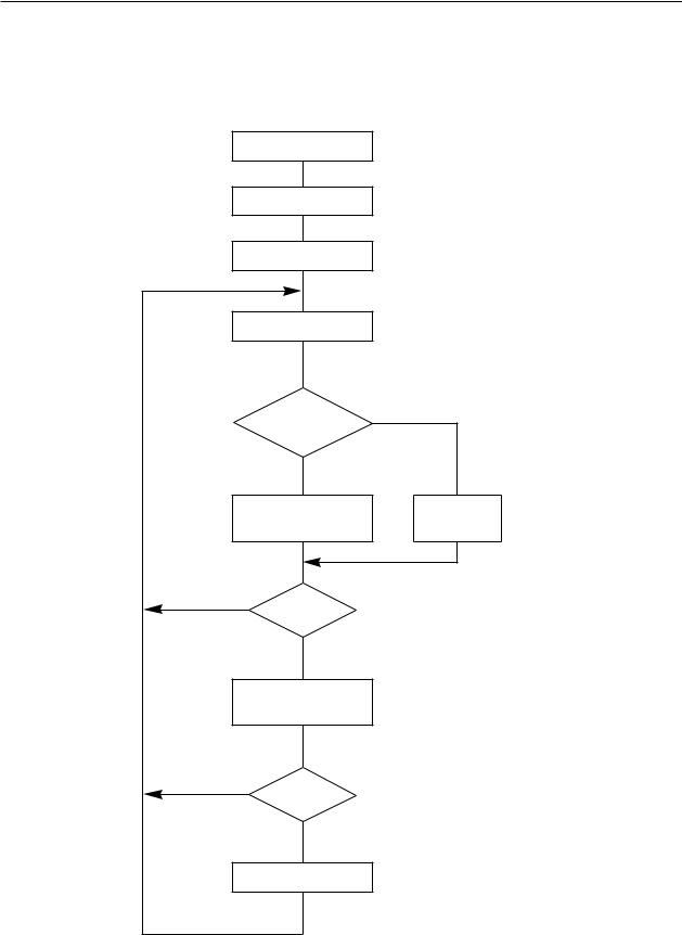
THEORY OF OPERATION
2.General Flow Chart (Main Logic Board)
The flow chart below shows you the general flow of editing and printing operations.
POWER ON |
|
|
Initialization |
|
|
Ready state |
|
|
Read data |
|
|
Control |
|
|
code? |
No |
|
YES |
|
|
Control code |
Data |
|
processing |
storage |
|
NO |
(Line buffer determination) |
|
Print? |
||
YES |
|
|
Data processing |
(Print out of data) |
|
or printing |
||
|
||
NO |
|
|
Return? |
|
|
YES |
|
|
Return action |
|
Fig. 2-2 General Flow Chart of Editing and Printing
– 22 –
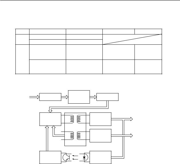
THEORY OF OPERATION
3.Power Supply Circuit
A ringing choke converter type circuit is used with a dropper type circuit in the power supply unit, fulfilling the input and output conditions described in the chart below.
Voltage Range |
Max. Current Output |
Service |
Circuit Type |
|
120VAC |
1.0 A |
|
|
|
Input |
0.6 A |
|
|
|
220Vto 240VAC |
|
|
|
|
5 VDC ±5% |
0.3A |
For logic |
circuit |
Dropper |
|
|
drive, for |
motor |
|
Output |
|
holding. |
|
|
|
|
|
|
|
33 VDC ±5% (LC-4511) |
3.2A(LC-4511) |
For print |
head |
Ringing choke |
40 VDC ±5% (LC-4521) |
4.4A (LC-4521) |
drive, for |
motor |
converter. |
|
|
drive. |
|
|
Input |
Noise filter |
In rush current |
Rectifier |
|
protection |
|
|||
circuit |
circuit |
|
||
120VAC |
circuit |
|
||
|
|
|
||
220VAC |
|
|
|
|
230VAC |
|
|
|
|
240VAC |
Switching |
|
Ringing |
|
|
|
Out put |
||
|
section |
|
choke |
|
|
|
33V DC ; LC-4511 |
||
|
(Transistor Q1) |
|
converter |
|
|
|
40V DC ; LC-4521 |
||
|
|
|
|
|
|
|
|
Dropper |
Out put |
|
|
|
circuit |
5V DC |
|
|
Transformer T1 |
|
|
|
|
PC1 |
|
|
|
Control |
|
Voltage |
|
|
circuit |
|
reference |
|
|
|
Photo-Coupler |
|
|
Fig. 2-3 Power Supply unit block diagram
– 23 –
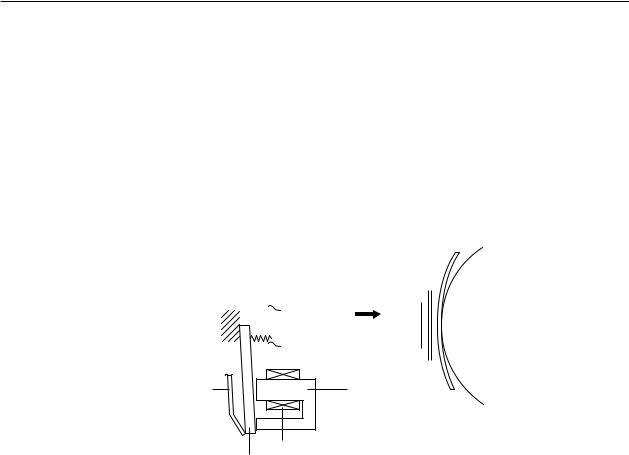
THEORY OF OPERATION
4.Mechanism
4-1. Print Head Mechanism
The print head consists of 24 needle wires and 24 print solenoids. The following explains how each needle wire operates during printing.
(1)When the print solenoid is energized, the clapper is attracted by the iron core and the needle wire is driven toward the platen.
(2)This needle wire hits the platen via the ink ribbon and paper. A single dot is printed on the paper.
(3)When the print solenoid is de-energized, the needle wire is returned to its original position by rebound energy and spring and clapper holder (leaf spring) force.
|
|
|
|
|
|
|
|
|
|
|
|
|
|
|
|
|
|
|
|
Paper |
||
|
|
|
|
|
|
|
|
|
|
|
|
|
Paper guide |
|
Platen |
|||||||
|
|
|
|
Spring |
|
|
|
|
|
|
Ink ribbon |
|
|
|
|
|
||||||
|
|
|
|
|
|
|
|
|
|
|
|
|
|
|
||||||||
Stopper |
Needle wire |
|
|
|
|
|||||||||||||||||
|
|
|
|
|
|
|
||||||||||||||||
|
|
|
|
|
|
|
||||||||||||||||
|
|
|
|
|
|
|
|
|
|
|
|
|
Guide |
|
|
|
|
|||||
|
|
|
|
|
|
|
|
|
|
|
|
|
|
|
|
|||||||
|
|
|
|
|
|
|
|
|
|
|
|
|
|
|
|
|
|
|
|
|
|
|
|
|
|
|
|
|
|
|
|
|
|
|
|
|
|
|
|
|
|
|
|
|
|
|
|
|
|
|
|
|
|
|
|
|
|
|
|
|
|
|
|
|
|
|
|
|
|
|
|
|
|
|
|
|
|
|
|
|
|
|
|
|
|
|
|
|
|
|
|
Subguide
Clapper holder |
Iron core |
Print solenoid
Clapper
Fig. 2-4 Outline of Print Head Mechanism
– 24 –

THEORY OF OPERATION
4-2. Print Head Carrying Mechanism
The print head carrying mechanism consists of a carriage, timing belt, carriage motor, and home position detector.
Carriage
The carriage is supported horizontally by the carriage stay and rear angle. The carriage moves from side to side with the print head mounted above it. A timing belt is clamped to the base of the carriage and a shield plate is mounted at the base for home position detection.
Timing Belt
The timing belt is suspended between the timing pulley of the carriage motor and the timing pulley of the tension lever. The timing belt maintains a constant tension.
The timing belt is also clamped to the base of the carriage so that it can move the carriage accurately with driving force from the carriage motor.
Carriage Motor
The carriage motor is a PM (permanent magnet) 4-phase, 48-pole pulse motor driven by pulse signals from the control circuit. The rotational rate depends on the number of pulses per unit time. By varying this rotational rate (carriage carrying rate), the size of the horizontal letters can be changed in each print mode.
Fig. 2-5 Print Head Carrying Mechanism
– 25 –
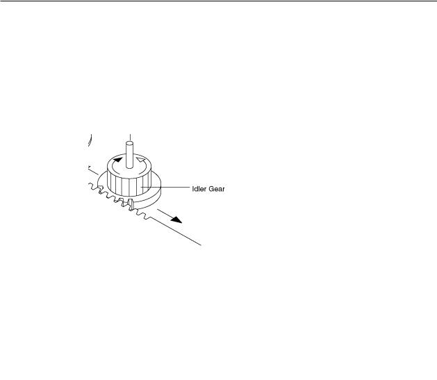
THEORY OF OPERATION
4-3. Ink ribbon feed mechanism
The ink ribbon feed mechanism is linked to the print head carrying mechanism so the ink ribbon always winds automatically in the same direction while the carriage moves left and right.
The movement of the carriage along the serrated edge of the rear angle of the printer mechanism drives the idler gear. The rotation of the idler gear is conveyed sequentially to the gears that work and wind the ribbon. The carriage has a clutch lever that keeps the direction of the cassette gear rotation constant, regardless of the direction of the idler gear rotation as the carriage moves left and right.
Fig. 2-6 Ribbon feed mechanism
– 26 –
Loading...