


 Loading...
SCARA ROBOT
LS20 series
MANIPULATOR MANUAL
Rev.1 |
EM158R3027F |
MANIPULATOR MANUAL |
seriesLS20 Rev |
.1 |
SCARA ROBOT
LS20 series Manipulator Manual
Rev.1
Copyright 2015 SEIKO EPSON CORPORATION. All rights reserved.
LS20 Rev.1 |
i |
FOREWORD
Thank you for purchasing our robot products.
This manual contains the information necessary for the correct use of the manipulator. Please carefully read this manual and other related manuals before installing the robot system.
Keep this manual handy for easy access at all times.
WARRANTY
The Manipulator and its optional parts are shipped to our customers only after being subjected to the strictest quality controls, tests, and inspections to certify its compliance with our high performance standards.
Product malfunctions resulting from normal handling or operation will be repaired free of charge during the normal warranty period. (Please ask your Regional Sales Office for warranty period information.)
However, customers will be charged for repairs in the following cases (even if they occur during the warranty period):
1.Damage or malfunction caused by improper use which is not described in the manual, or careless use.
2.Malfunctions caused by customers’ unauthorized disassembly.
3.Damage due to improper adjustments or unauthorized repair attempts.
4.Damage caused by natural disasters such as earthquake, flood, etc.
Warnings, Cautions, Usage:
1.If the Manipulator or associated equipment is used outside of the usage conditions and product specifications described in the manuals, this warranty is void.
2.If you do not follow the WARNINGS and CAUTIONS in this manual, we cannot be responsible for any malfunction or accident, even if the result is injury or death.
3.We cannot foresee all possible dangers and consequences. Therefore, this manual cannot warn the user of all possible hazards.
ii |
LS20 Rev.1 |

TRADEMARKS
Microsoft, Windows, and Windows logo are either registered trademarks or trademarks of Microsoft Corporation in the United States and/or other countries. Other brand and product names are trademarks or registered trademarks of the respective holders.
NOTICE
No part of this manual may be copied or reproduced without authorization. The contents of this manual are subject to change without notice.
Please notify us if you should find any errors in this manual or if you have any comments regarding its contents.
INQUIRIES
Contact the following service center for robot repairs, inspections or adjustments.
If service center information is not indicated below, please contact the supplier office for your region.
Please prepare the following items before you contact us.
-Your controller model and its serial number
-Your manipulator model and its serial number
-Software and its version in your robot system
-A description of the problem
SERVICE CENTER
LS20 Rev.1 |
iii |

MANUFACTURER
Toyoshina Plant
Robotics Solutions Operations Division
6925 Toyoshina Tazawa,
Azumino-shi, Nagano, 399-8285
JAPAN
TEL
FAX
SUPPLIERS
North & South America Epson America, Inc. |
|
Factory Automation/Robotics |
|
18300 Central Avenue |
|
Carson, CA 90746 |
|
USA |
|
TEL |
: +1-562-290-5900 |
FAX |
: +1-562-290-5999 |
: info@robots.epson.com |
|
Europe |
Epson Deutschland GmbH |
|
|
Factory Automation Division |
|
|
Otto-Hahn-Str.4 |
|
|
D-40670 Meerbusch |
|
|
Germany |
|
|
TEL |
: +49-(0)-2159-538-1391 |
|
FAX |
: +49-(0)-2159-538-3170 |
|
: robot.infos@epson.de |
|
China |
Epson (China) Co., Ltd. |
|
|
Factory Automation Division |
|
|
7F, Jinbao Building No. 89, Jinbao Street, |
|
|
Dongcheng District, Beijing, |
|
|
China, 100005 |
|
|
TEL |
: +86-(0)-10-8522-1199 |
|
FAX |
: +86-(0)-10-8522-1120 |
Taiwan |
Epson Taiwan Technology & Trading Ltd. |
|
|
Factory Automation Division |
|
|
14F, No.7, Song Ren Road, Taipei 110, |
|
|
Taiwan, ROC |
|
|
TEL |
: +886-(0)-2-8786-6688 |
|
FAX |
: +886-(0)-2-8786-6677 |
iv |
LS20 Rev.1 |
Korea |
Epson Korea Co., Ltd. |
|
|
Marketing Team (Robot Business) |
|
|
27F DaeSung D-Polis A, 606 |
|
|
Seobusaet-gil, Geumcheon-gu, Seoul, 153-803 |
|
|
Korea |
|
|
TEL |
: +82-(0)-2-3420-6692 |
|
FAX |
: +82-(0)-2-558-4271 |
Southeast Asia |
Epson Singapore Pte. Ltd. |
|
|
Factory Automation System |
|
|
1 HarbourFront Place, #03-02, |
|
|
HarbourFront Tower One, |
|
|
Singapore 098633 |
|
|
TEL |
: +65-(0)-6586-5696 |
|
FAX |
: +65-(0)-6271-3182 |
India |
Epson India Pvt. Ltd. |
|
|
Sales & Marketing (Factory Automation) |
|
|
12th Floor, The Millenia, Tower A, No. 1, |
|
|
Murphy Road, Ulsoor, Bangalore, |
|
|
India 560008 |
|
|
TEL |
: +91-80-3051-5000 |
|
FAX |
: +91-80-3051-5005 |
Japan |
Epson Sales Japan Corporation |
|
|
Factory Automation Systems Department |
|
|
Nishi-Shinjuku Mitsui Bldg. 6-24-1 |
|
|
Nishishinjuku, Shinjuku-ku, Tokyo 160-8324 |
|
|
Japan |
|
|
TEL |
: +81-(0)3-5321-4161 |
LS20 Rev.1 |
v |

For Customers in the European Union
The crossed out wheeled bin label that can be found on your product indicates that this product and incorporated batteries should not be disposed of via the normal household waste stream. To prevent possible harm to the environment or human health please separate this product and its batteries from other waste streams to ensure that it can be recycled in an environmentally sound manner. For more details on available collection facilities please contact your local government office or the retailer where you purchased this product. Use of the chemical symbols Pb, Cd or Hg indicates if these metals are used in the battery.
This information only applies to customers in the European Union, according to DIRECTIVE 2006/66/EC OF THE EUROPEAN PARLIAMENT AND OF THE COUNCIL OF 6 September 2006 on batteries and accumulators and waste batteries and accumulators and repealing Directive 91/157/EEC and legislation transposing and implementing it into the various national legal systems.
For other countries, please contact your local government to investigate the possibility of recycling your product.
The battery removal/replacement procedure is described in the following manuals:
Controller manual / Manipulator manual (Maintenance section)
vi |
LS20 Rev.1 |

Before Reading This Manual
This section describes what you should know before reading this manual.
Structure of Control System
The LS20 series Manipulators can be used with the following combinations of Controllers and software.
Robot Controller RC90 with the following label attached.
Label |
Controller |
Software |
RC90 EPSON RC+ 7.0 Ver.7.1.4 or later
Turning ON/OFF Controller
When you see the instruction “Turn ON/OFF the Controller” in this manual, be sure to turn ON/OFF all the hardware components. For the Controller composition, refer to the table above.
Shape of Motors
The shape of the motors used for the Manipulator that you are using may be different from the shape of the motors described in this manual because of the specifications.
Setting by Using Software
This manual contains setting procedures by using software. They are marked with the following icon.
EPSON
RC+
Figures in this Manual
The figures of manipulators indicated in this manual are basically Standard-model Manipulator. Unless special instruction is provided, the specifications of Standard-model and Cleanroom-model are the same.
Photos and Illustrations Used in This Manual
The appearance of some parts may differ from those on an actual product depending on when it was shipped or the specifications. The procedures themselves, however, are accurate.
LS20 Rev.1 |
vii |
viii |
LS20 Rev.1 |
|
|
|
|
TABLE OF CONTENTS |
Setup & Operation |
|
|
||
|
|
|
|
|
|
1. |
Safety |
|
3 |
1.1 |
Conventions................................................................................................ |
3 |
||
1.2 |
Design and Installation Safety.................................................................... |
4 |
||
|
|
1.2.1 Strength of Ball Screw Spline......................................................... |
5 |
|
1.3 |
Operation Safety ........................................................................................ |
6 |
||
1.4 |
Emergency Stop......................................................................................... |
8 |
||
1.5 |
Emergency Movement Without Drive Power ........................................... |
10 |
||
1.6 |
ACCELS Setting for CP Motions.............................................................. |
11 |
||
1.7 |
Manipulator Labels................................................................................... |
12 |
||
|
|
|
||
|
2. |
Specifications |
14 |
|
2.1 |
Features of LS20 series Manipulators ..................................................... |
14 |
||
2.2 |
Model Number.......................................................................................... |
15 |
||
2.3 |
Part Names and Outer Dimensions ......................................................... |
16 |
||
|
|
2.3.1 |
LS20-804*..................................................................................... |
16 |
|
|
2.3.2 |
LS20-A04* .................................................................................... |
20 |
2.4 |
Specifications ........................................................................................... |
24 |
||
2.5 |
How to Set the Model............................................................................... |
26 |
||
|
|
|
||
|
3. |
Environments and Installation |
27 |
|
3.1 |
Environmental Conditions ........................................................................ |
27 |
||
3.2 |
Base Table................................................................................................ |
28 |
||
3.3 |
Mounting Dimensions............................................................................... |
29 |
||
|
|
3.3.1 |
LS20-804*..................................................................................... |
29 |
|
|
3.3.2 |
LS20-A04* .................................................................................... |
31 |
3.4 |
Unpacking and Transportation ................................................................. |
33 |
||
|
|
3.4.1 Precautions for Transportation........................................................ |
33 |
|
|
|
3.4.2 Transportation ................................................................................. |
34 |
|
3.5 |
Installation Procedure............................................................................... |
35 |
||
|
|
3.5.1 |
Standard-Model ............................................................................ |
35 |
|
|
3.5.2 |
Cleanroom-Model......................................................................... |
36 |
3.6 |
Connecting the Cables............................................................................. |
37 |
||
3.7 |
User Wires and Pneumatic Tubes............................................................ |
38 |
||
3.8 |
Relocation and Storage............................................................................ |
39 |
||
|
|
3.8.1 Precautions for Relocation and Storage ...................................... |
39 |
|
|
|
3.8.2 |
Relocation..................................................................................... |
40 |
|
|
|
||
|
4. Setting of End Effectors |
41 |
||
4.1 |
Attaching an End Effector......................................................................... |
41 |
||
4.2 |
Attaching Cameras and Valves ................................................................ |
42 |
||
4.3 |
Weight and Inertia Settings ...................................................................... |
43 |
||
|
|
4.3.1 |
Weight Setting .............................................................................. |
43 |
|
|
4.3.2 |
Inertia Setting ............................................................................... |
45 |
LS20 Rev.1 |
|
|
ix |
|

TABLE OF CONTENTS
4.4 Precautions for Auto Acceleration/Deceleration of Joint #3..................... |
49 |
5. |
Motion Range |
50 |
5.1 |
Motion Range Setting by Pulse Range (for All Joints)............................. |
50 |
|
5.1.1 Max. Pulse Range of Joint #1...................................................... |
51 |
|
5.1.2 Max. Pulse Range of Joint #2...................................................... |
51 |
|
5.1.3 Max. Pulse Range of Joint #3...................................................... |
52 |
|
5.1.4 Max. Pulse Range of Joint #4...................................................... |
52 |
5.2 |
Motion Range Setting by Mechanical Stops ............................................ |
53 |
|
5.2.1 Setting the Mechanical Stops of Joints #1 and #2....................... |
54 |
|
5.2.2 Setting the Mechanical Stop of Joint #3....................................... |
56 |
5.3 |
Setting the Cartesian (Rectangular) Range in the XY Coordinate |
|
|
System of the Manipulator (for Joints #1 and #2) ................................... |
58 |
5.4 |
Standard Motion Range ........................................................................... |
58 |
Maintenance
|
1. |
...................................................................Safety Maintenance |
61 |
|
|
|
|
||
|
2. |
General Maintenance................................................................. |
62 |
|
2.1 |
Maintenance Inspection........................................................................... |
62 |
||
|
|
2.1.1 Schedule for Maintenance Inspection.......................................... |
62 |
|
|
|
2.1.2 |
Inspection Point ............................................................................ |
63 |
2.2 |
Overhaul................................................................................................... |
64 |
||
2.3 |
Greasing................................................................................................... |
65 |
||
2.4 |
Tightening Hexagon Socket Head Cap Bolts .......................................... |
66 |
||
2.5 |
Matching Origins ...................................................................................... |
66 |
||
2.6 |
Layout of Maintenance Parts ................................................................... |
67 |
||
|
|
|
|
|
|
3. |
Covers |
........................................................................................ |
68 |
3.1 |
Arm Top Cover ......................................................................................... |
69 |
||
3.2 |
Arm Bottom ....................................................................................Cover |
70 |
||
3.3 |
Arm #1 ...........................................................................................Cover |
70 |
||
3.4 |
Connector .......................................................................................Plate |
71 |
||
3.5 |
Connector ................................................................................Sub Plate |
72 |
||
3.6 |
User Plate................................................................................................. |
72 |
||
|
|
|
|
|
|
4. |
Cable.......................................................................................... |
|
73 |
4.1 |
Replacing Cable Unit ............................................................................... |
73 |
||
4.2 |
Wiring .......................................................................................Diagrams |
78 |
||
|
|
4.2.1 ................................................................................. |
Signal Cable |
78 |
|
|
4.2.2 ................................................................................. |
Power Cable |
79 |
|
|
4.2.3 ................................................................................... |
User Cable |
80 |
4.3 |
Replacing ...............................................................................M/C Cable |
81 |
||
x |
|
|
LS20 Rev.1 |
|

TABLE OF CONTENTS
5. |
........................................................................................Arm #1 |
|
84 |
|
5.1 |
|
Replacing Joint #1 Motor ......................................................................... |
85 |
|
5.2 |
|
Replacing Joint #1 Reduction Gear Unit.................................................. |
88 |
|
|
|
|
|
|
6. |
Arm #2........................................................................................ |
|
91 |
|
6.1 |
|
Replacing Joint #2 Motor ......................................................................... |
92 |
|
6.2 |
|
Replacing Joint #2 Reduction Gear Unit.................................................. |
96 |
|
|
|
|
|
|
7. |
Arm #3...................................................................................... |
|
100 |
|
7.1 |
|
Replacing Joint #3 Motor ....................................................................... |
101 |
|
7.2 |
|
Replacing the Timing Belt ...................................................................... |
105 |
|
7.3 |
|
Replacing the Brake............................................................................... |
109 |
|
7.4 |
|
Checking the Timing Belt Tension.......................................................... |
113 |
|
|
|
|
|
|
8. |
Arm #4...................................................................................... |
|
114 |
|
8.1 |
|
Replacing Joint #4 Motor ....................................................................... |
115 |
|
8.2 |
|
Replacing the Timing Belt ...................................................................... |
119 |
|
8.3 |
|
Replacing the Brake............................................................................... |
123 |
|
8.4 |
|
Replacing the Reduction Gear Unit ....................................................... |
124 |
|
8.5 |
|
Checking the Timing Belt Tension.......................................................... |
126 |
|
|
|
|
|
|
9. |
Bellows ..................................................................................... |
|
127 |
|
|
|
|||
10. Ball Screw Spline Unit ............................................................ |
129 |
|||
10.1 Greasing the Ball Screw Spline Unit .................................................... |
129 |
|||
|
|
10.1.1 |
Standard-model (S type) .......................................................... |
130 |
|
|
10.1.2 |
Cleanroom-model..................................................................... |
131 |
10.2 Replacing the Ball Screw Spline Unit................................................... |
133 |
|||
|
|
|
|
|
11. |
|
Lithium Battery........................................................................ |
136 |
|
11.1 Replacing the Battery Unit (Lithium Battery)........................................ |
138 |
|||
11.2 Replacing the Resolver Board.............................................................. |
139 |
|||
11.3 Replacing the Control Board ................................................................ |
141 |
|||
|
|
|
|
|
12. |
|
LED Lamp .............................................................................. |
142 |
|
|
|
|
|
|
13. |
|
Calibration .............................................................................. |
143 |
|
13.1 |
About Calibration.................................................................................. |
143 |
||
13.2 |
Calibration Procedure........................................................................... |
144 |
||
13.3 Accurate Calibration of Joint #2 ........................................................... |
154 |
|||
13.4 Calibration Procedure without using Calibration Wizard ..................... |
156 |
|||
|
|
|
|
|
14. |
|
Maintenance Parts List ........................................................... |
160 |
|
LS20 Rev.1 |
xi |

TABLE OF CONTENTS
xii |
LS20 Rev.1 |

Setup & Operation
This volume contains information for setup and operation of the LS20 series Manipulators.
Please read this volume thoroughly before setting up and operating the Manipulators.

Setup & Operation 1. Safety
1.Safety
Installation and transportation of robots and robotic equipment shall be performed by qualified personnel and should conform to all national and local codes. Please read this manual and other related manuals before installing the robot system or before connecting cables.
Keep this manual handy for easy access at all times.
1.1Conventions
Important safety considerations are indicated throughout the manual by the following symbols. Be sure to read the descriptions shown with each symbol.
|
This symbol indicates that a danger of possible serious injury or |
|
death exists if the associated instructions are not followed |
WARNING |
properly. |
|
|
|
This symbol indicates that a danger of possible serious injury or |
|
death caused by electric shock exists if the associated |
WARNING |
instructions are not followed properly. |
|
|
|
This symbol indicates that a danger of possible harm to people |
|
or physical damage to equipment and facilities exists if the |
CAUTION |
associated instructions are not followed properly. |
|
|
LS20 Rev.1 |
3 |
Setup & Operation 1. Safety
1.2Design and Installation Safety
Only trained personnel should design and install the robot system. Trained personnel are defined as those who have taken robot system training and maintenance training classes held by the manufacturer, dealer, or local representative company, or those who understand the manuals thoroughly and have the same knowledge and skill level as those who have completed the training courses.
To ensure safety, a safeguard must be installed for the robot system. For details on the safeguard, refer to the Installation and Design Precautions in the Safety chapter of the EPSON RC+ User’s Guide.
The following items are safety precautions for design personnel:
■Personnel who design and/or construct the robot system with this product must read the Safety chapter in the EPSON RC+ User’s Guide to understand the safety requirements before designing and/or constructing the robot system. Designing and/or constructing the robot system without understanding the safety requirements is extremely hazardous, may result in serious bodily injury and/or severe equipment damage to the robot system, and may cause serious safety problems.
■The Manipulator and the Controller must be used within the environmental conditions described in their respective manuals. This product has been
WARNING |
designed and manufactured strictly for use in a normal indoor environment. Using |
|
the product in an environment that exceeds the specified environmental |
|
conditions may not only shorten the life cycle of the product but may also cause |
|
serious safety problems. |
■The robot system must be used within the installation requirements described in the manuals. Using the robot system outside of the installation requirements may not only shorten the life cycle of the product but also cause serious safety problems.
Further precautions for installation are mentioned in the chapter Setup & Operation: 3. Environments and Installation. Please read this chapter carefully to understand safe installation procedures before installing the robots and robotic equipment.
4 |
LS20 Rev.1 |

Setup & Operation 1. Safety
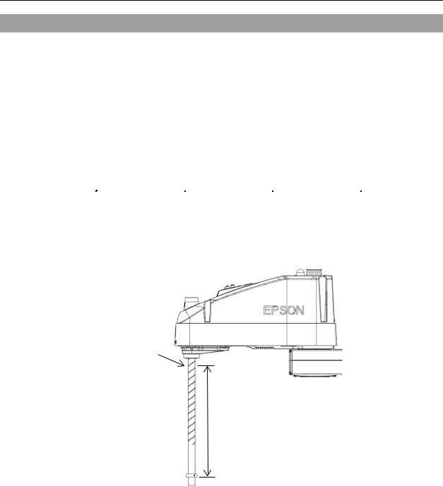
1.2.1Strength of Ball Screw Spline
If a bending load exceeding the allowable limit is placed on the ball screw spline, the spline may be deformed or broken and not function normally.
If the load exceeding the allowance is placed, the ball screw spline needs to be replaced. The allowable load depends on distance that the load is placed. Calculate the value by referring to the following.
[Allowable bending moment]
M=50,000 N∙mm
Calculation example:
110 N (11.2 kgf) load is placed at 400 mm from the end of the spline nut
[Moment]
M=F∙L 110·400 44,000 N∙mm
 End of spline nut
L
F
LS20 Rev.1 |
5 |

Setup & Operation 1. Safety
1.3Operation Safety
The following items are safety precautions for qualified Operator personnel:
■Please carefully read the Safety-related Requirements in the Safety chapter of the EPSON RC+ User’s Guide before operating the robot system. Operating the robot system without understanding the safety requirements is extremely hazardous and may result in serious bodily injury and/or severe equipment damage to the robot system.
■Do not enter the operating area of the Manipulator while the power to the robot system is turned ON. Entering the operating area with the power ON is extremely hazardous and may cause serious safety problems as the Manipulator may move even if it seems to be stopped.
■Before operating the robot system, make sure that no one is inside the safeguarded area. The robot system can be operated in the mode for teaching
WARNING |
even when someone is inside the safeguarded area. |
|
The motion of the Manipulator is always in restricted (low speeds and low power) |
|
status to secure the safety of an operator. However, operating the robot system |
|
while someone is inside the safeguarded area is extremely hazardous and may |
|
result in serious safety problems in case that the Manipulator moves |
|
unexpectedly. |
■Immediately press the Emergency Stop switch whenever the Manipulator moves abnormally while the robot system is operated. Continuing the operation while the Manipulator moves abnormally is extremely hazardous and may result in serious bodily injury and/or severe equipment damage to the robot system.
■To shut off power to the robot system, pull out the power plug from the power source. Be sure to connect the AC power cable to a power receptacle. DO NOT connect it directly to a factory power source.
■Before performing any replacement procedure, turn OFF the Controller and related equipment, and then pull out the power plug from the power source. Performing any replacement procedure with the power ON is extremely hazardous and may result in electric shock and/or malfunction of the robot
WARNING system.
■Do not insert or pull out the motor connectors while the power to the robot system is turned ON. Inserting or pulling out the motor connectors with the power ON is extremely hazardous and may result in serious bodily injury as the Manipulator may move abnormally, and also may result in electric shock and/or malfunction of the robot system.
6 |
LS20 Rev.1 |
Setup & Operation 1. Safety
■Whenever possible, only one person should operate the robot system. If it is necessary to operate the robot system with more than one person, ensure that all people involved communicate with each other as to what they are doing and take all necessary safety precautions.
■Joint #1, #2, and #4:
If the joints are operated repeatedly with the operating angle less than 5 degrees, they may get damaged early because the bearings are likely to cause oil film shortage in such situation. To prevent early breakdown, move the joints larger than 50 degrees for about five to ten times a day.
Joint #3:
CAUTION If the up-and-down motion of the hand is less than 10 mm, move the joint a half of the maximum stroke for five to ten times a day.
■Oscillation (resonance) may occur continuously in low speed Manipulator motion (Speed: approx. 5 to 20%) depending on combination of Arm orientation and end effector load. Oscillation arises from natural oscillation frequency of the Arm and can be controlled by following measures.
Changing Manipulator speed
Changing the teach points
Changing the end effector load
LS20 Rev.1 |
7 |

Setup & Operation 1. Safety
1.4Emergency Stop
If the Manipulator moves abnormally during operation, immediately press the Emergency Stop switch. Pressing the Emergency Stop switch immediately changes the manipulator to deceleration motion and stops it at the maximum deceleration speed.
However, avoid pressing the Emergency Stop switch unnecessarily while the Manipulator is running normally. Pressing the Emergency Stop switch locks the brake and it may cause wear on the friction plate of the brake, resulting in the short life of the brake.
Normal brake life cycle: About 2 years (when the brakes are used 100 times/day)
To place the system in emergency mode during normal operation, press the Emergency Stop switch when the Manipulator is not moving.
Refer to the Controller manual for instructions on how to wire the Emergency Stop switch circuit.
Do not turn OFF the Controller while the Manipulator is operating.
If you attempt to stop the Manipulator in emergency situations such as “Safeguard Open”, make sure to stop the Manipulator using the E-Stop of the Controller.
If the Manipulator is stopped by turning OFF the Controller while it is operating, following problems may occur.
Reduction of the life and damage of the reduction gear unit Position gap at the joints
In addition, if the Controller was forced to be turned OFF by blackouts and the like while the Manipulator is operating, make sure to check the following points after power restoration.
Whether or not the reduction gear is damaged Whether or not the joints are in their proper positions
If there is a position gap, perform calibration by referring to the Maintenance 16. Calibration in this manual.
Before using the Emergency Stop switch, be aware of the followings.
-The Emergency Stop (E-STOP) switch should be used to stop the Manipulator only in case of emergencies.
-To stop the Manipulator operating the program except in emergency, use Pause (halt) or STOP (program stop) commands.
Pause and STOP commands do not turn OFF the motors. Therefore, the brake does not function.
-For the Safeguard system, do not use the circuit for E-STOP.
For details of the Safeguard system, refer to the following manuals.
EPSON RC+ User’s Guide
2. Safety - Installation and Design Precautions - Safeguard System
Safety and Installation
2.6 Connection to EMERGENCY Connector
8 |
LS20 Rev.1 |

Setup & Operation 1. Safety
To check brake problems, refer to the following manuals.
Manipulator Manual Maintenance
2.1.2 Inspection While the Power is ON (Manipulator is operating)
Safety and Installation
5.1.1 Manipulator - Inspection While the Power is ON (Manipulator is operating)
Free running distance in emergency
The operating Manipulator cannot stop immediately after the Emergency Stop switch is pressed.
The free running time/angle/distance of the Manipulator are shown below. However, remember that the values vary depending on following conditions.
Weight of the end effector Weight of work piece Operating pose Weight Speed Accel etc.
Conditions for Measurement |
|
||||
|
|
LS20-804* LS20-A04* |
|
||
|
Accel Setting |
100 |
100 |
|
|
|
Speed Setting |
100 |
100 |
|
|
|
Load [kg] |
20 |
20 |
|
|
|
Weight Setting |
20 |
20 |
|
|
|
|
|
|
|
|
|
|
|
|
|
Motion start |
|
|
|
|
|
position |
|
|
|
|
|
|
|
|
|
|
|
|
|
E-Stop signal |
|
|
|
|
|
|
|
|
Target position |
|
|
Input position |
|
|
Joint #1 |
|
|
|
|
|
|
|
|
|
|
|
|
|
|
Joint #2 |
|
|
Stop position |
|
|
|
|
|
|
|
|
|
|
|
|
|
|
|
|
|
|
|
|
|
|
|
|
|
|
|
|
|
||
|
Controller |
|
|
|
RC90 |
|||
|
|
|
|
|
|
|||
|
Manipulator |
|
LS20-804* |
|
LS20-A04* |
|||
|
|
|
|
|
|
|
|
|
Free running time |
Joint #1 + Joint #2 |
[sec.] |
|
0.65 |
|
|
0.7 |
|
|
|
|
|
|
|
|
|
|
Joint #3 |
[sec.] |
|
|
|
0.3 |
|||
|
|
|
|
|||||
|
|
|
|
|
|
|
||
|
Joint #1 |
[deg.] |
|
65 |
|
|
70 |
|
|
|
|
|
|
|
|
|
|
Free running angle |
Joint #2 |
[deg.] |
|
50 |
|
|
50 |
|
|
|
|
|
|
|
|
|
|
|
Joint #1 + Joint #2 |
[deg.] |
|
115 |
|
|
120 |
|
|
|
|
|
|
|
|
|
|
Free running distance |
Joint #3 |
[mm] |
|
|
|
110 |
||
|
|
|
|
|
|
|
|
|
LS20 Rev.1 |
9 |

Setup & Operation 1. Safety
1.5Emergency Movement Without Drive Power
When the system is placed in emergency mode, push the arm or joint of the Manipulator by hand as shown below:
Arm #1 |
Push the arm by hand. |
Arm #2 |
Push the arm by hand. |
Joint #3 |
The joint cannot be moved up/down by hand until the solenoid |
|
brake applied to the joint has been released. Move the joint |
|
up/down while pressing the brake release switch. |
Joint #4 The shaft cannot be rotated by applied to the shaft is released. the brake release switch.
hand until the solenoid brake Move the shaft while pressing
Joint #3 / Joint #4 brake release switch
Arm #2
+
Joint #3
(up and down)  Shaft
Shaft
− −
+
Joint #4 (rotating)
Joint #2 (rotating)
−+
Joint #1 (rotating)
−
+
Arm #1
Base
Figure: LS20−804S
NOTE
is pressed in emergency mode, the brakes for both Joints #3 and #4 are released simultaneously.
Be careful of the shaft falling and rotating while the brake release switch is pressed because the shaft may be lowered by the weight of the end effector.When the brake release switchThe brake release switch affects both Joints #3 and #4.
10 |
LS20 Rev.1 |
Setup & Operation 1. Safety
1.6ACCELS Setting for CP Motions
To make the Manipulator move in CP motion, see the following and set ACCELS properly according to the motion area, load, and Z-axis height.
|
NOTE Improper setting may cause following problems. |
|
|
|||
|
|
Reduction of the life and damage of the ball screw spline |
|
|||
|
Set ACCELS as follows according to the Z-axis height. |
|
||||
|
|
ACCELS setting value by Z-axis position and tip load |
|
|||
|
|
|
|
|
||
Z position |
|
Tip load (kg) |
|
|||
|
(mm) |
5 kg or less |
10 kg or less |
|
15 kg or less |
20 kg or less |
0 |
> Z >= - 100 |
|
10000 or less |
|
10000 or less |
9000 or less |
- 100 |
> Z >= - 200 |
10000 or less |
|
7000 or less |
5500 or less |
|
|
|
|||||
- 200 |
> Z >= - 300 |
7500 or less |
|
5000 or less |
3500 or less |
|
|
|
|||||
- 300 |
> Z >= - 420 |
|
5500 or less |
|
3500 or less |
2500 or less |
Z-axis height 0 (Origin point)
Z
If the Manipulator is operated in CP motion with the wrong set values, make sure to check the following point.
Whether the ball screw spline shaft is deformed or bent
LS20 Rev.1 |
11 |

Setup & Operation 1. Safety
1.7Manipulator Labels
The following labels are attached near the locations of the Manipulator where specific dangers exist.
Be sure to comply with descriptions and warnings on the labels to operate and maintain the Manipulator safely.
Do not tear, damage, or remove the labels. Use meticulous care when handling those parts or units to which the following labels are attached as well as the nearby areas:
|
Labels |
|
NOTE |
|
|
|
|
||
|
|
Before loosening the base mounting screws, |
||
A |
|
hold the arm and secure it tightly with a band |
||
|
to prevent hands or fingers from being |
|||
|
|
|||
|
|
caught in the Manipulator. |
|
|
|
|
|
||
|
|
Do not enter the operation area while the |
||
B |
|
Manipulator is moving. The robot arm may |
||
|
collide against |
the operator. |
This is |
|
|
|
extremely hazardous and may result in |
||
|
|
serious safety problems. |
|
|
|
|
|
||
C |
|
Hazardous voltage exists while the |
||
|
Manipulator is ON. To avoid electric shock, |
|||
|
|
do not touch any internal electric parts. |
||
|
|
|
||
|
|
You can catch your hand or fingers between |
||
|
|
the shaft and cover when bringing your hand |
||
D |
|
close to moving parts. |
|
|
|
* Manipulators with bellows do not have this |
|||
|
|
|||
|
|
label for no danger of your hand or fingers |
||
|
|
being caught. |
|
|
|
|
|
||
|
|
Only authorized personnel should perform |
||
|
|
sling work and operate a crane and a forklift. |
||
E |
|
When these operations are performed by |
||
|
unauthorized personnel, it is extremely |
|||
|
|
hazardous and may result in serious bodily |
||
|
|
injury and/or severe equipment damage to |
||
|
|
the robot system. |
|
|
|
|
|
||
|
|
Be careful of the shaft falling and rotating |
||
F |
|
while the brake |
release switch is |
pressed |
|
because the shaft may be lowered by the |
|||
|
|
|||
|
|
weight of the end effector. |
|
|
|
|
|
|
|
12 |
LS20 Rev.1 |

Setup & Operation 1. Safety
|
Labels |
NOTE |
|
|
|
G
F C
D
|
|
|
|
|
|
|
C |
|
|
|
|
|
|
|
|
|
|
|
|
|
|
|
|
|
|
|
|
|
|
|
|
|
|
(Opposite side) |
|
E |
|
|
|
|
|
|
|
|
|
||
|
|
||||||
|
|
|
|
|
|
|
|
(Opposite side) G
|
|
A |
B |
(Figure: LS20-804S)
LS20 Rev.1 |
13 |

Setup & Operation 2. Specifications
2.Specifications
2.1Features of LS20 series Manipulators
The LS20 series Manipulators are advanced manipulators pursuing high speed and high cost-performance.
The features of the LS20 series Manipulators are as follows:
Resolver for the Position Detector
It includes no electrical components; therefore it has high resistance to environment and hardly breaks down.
It mounts the resolver board and battery inside the manipulator; therefore the calibration is not required when you disconnect the M/C cable.
Large Capacity
It supports the U-axis allowable moment up to 0.45 kg·m2
It stably handles large loads by optimized control based on the each load.
Tact Time Improvement by High-speed Motion
It improves the tact time of delicate movements by acceleration/deceleration speed optimized for each payload and stop short technology.
14 |
LS20 Rev.1 |
Setup & Operation 2. Specifications
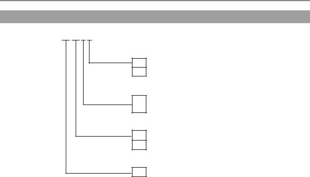
2.2Model Number
LS20-80 4 S
Environment
S : Standard
C : Cleanroom
Joint #3 stroke
4: 420 mm : Standard-Model
: 390 mm : Cleanroom-Model (with bellows)
Arm length
80 : 800 mm
A0 : 1000 mm
Payload
20 : 20 kg
Environment
Cleanroom-model
This model has additional features that reduce dust emitted by the Manipulator to enable use in clean room environments.
For details on the specifications, refer to Setup & Operation: 2.4 Specifications.
Payload |
Arm length |
Environment |
Joint #3 stroke |
Model Number |
|
|
800 mm |
Standard |
420 mm |
LS20-804S |
|
20 kg |
Cleanroom |
390 mm |
LS20-804C |
||
|
|||||
1000 mm |
Standard |
420 mm |
LS20-A04S |
||
|
|||||
|
Cleanroom |
390 mm |
LS20-A04C |
||
|
|
LS20 Rev.1 |
15 |
Setup & Operation 2. Specifications
2.3Part Names and Outer Dimensions
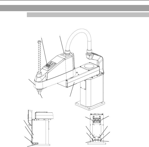
2.3.1LS20-804*
LS20-804S (Standard-Model)
Joint #3 / Joint #4 |
|
|
LED lamp |
||
Brake release switch |
||
|
Arm #2
Shaft |
Arm #1 |
|
|
|
|
|
|
|
Signal cable |
KC Mark |
|
|
|
User connector |
||
Signature label |
|
|
|
|||
|
|
|
(9-pin D-sub connector) |
|||
(Serial No. |
|
|
|
|||
|
|
|
|
|||
of Manipulator) |
|
|
|
Fittings (white) for ø4 mm |
||
|
MT label |
|
|
|
pneumatic tube |
|
|
|
|
|
|||
|
|
|
|
|||
(only for custom |
|
|
|
Fittings (white) for ø6 mm |
||
specification) |
|
|
|
|||
|
|
|
pneumatic tube |
|||
|
|
|
|
|
|
|
|
CE label |
|
||||
|
|
|
|
|
|
|
 Base
Base
Power cable
User connector
(15-pin D-sub connector)
Fittings (blue)
for ø4 mm pneumatic tube
Fittings (blue) for ø6 mm pneumatic tube
NOTE
in emergency mode, the brakes for both Joints #3 and #4 are released simultaneously.
-While the LED lamp is on, the current is being applied to the manipulator. Performing any work with the power ON is extremely hazardous and it may result in electric shock and/or improper
function of the robot system. Make sure to turn OFF the controller power before the maintenance work.- The brake release switch affects both Joints #3 and #4. When the brake release switch is pressed
16 |
LS20 Rev.1 |
Loading...