


SERVICE MANUAL
Color Inkjet Printer
L1800
Confidential
SEIJ13-007
Notice:
All rights reserved. No part of this manual may be reproduced, stored in a retrieval system, or transmitted in any form or by any means, electronic, mechanical, photocopying, recording, or otherwise, without the prior written permission of SEIKO EPSON CORPORATION.
The contents of this manual are subject to change without notice.
All effort have been made to ensure the accuracy of the contents of this manual. However, should any errors be detected, SEIKO EPSON would greatly appreciate being informed of them.
The above not withstanding SEIKO EPSON CORPORATION can assume no responsibility for any errors in this manual or the consequences thereof.
EPSON is a registered trademark of SEIKO EPSON CORPORATION.
General Notice: |
Other product names used herein are for identification purpose only and may be trademarks or registered trademarks of their |
|
respective owners. EPSON disclaims any and all rights in those marks. |
Copyright © 2014 SEIKO EPSON CORPORATION.
Printer CS Quality Assurance Department
Confidential
PRECAUTIONS
Precautionary notations throughout the text are categorized relative to 1)Personal injury and 2) damage to equipment.
DANGER |
Signals a precaution which, if ignored, could result in serious or fatal personal injury. Great caution should be exercised in performing procedures preceded by |
|
DANGER Headings. |
WARNING |
Signals a precaution which, if ignored, could result in damage to equipment. |
The precautionary measures itemized below should always be observed when performing repair/maintenance procedures.
DANGER
1.ALWAYS DISCONNECT THE PRODUCT FROM THE POWER SOURCE AND PERIPHERAL DEVICES PERFORMING ANY MAINTENANCE OR REPAIR PROCEDURES.
2.NO WORK SHOULD BE PERFORMED ON THE UNIT BY PERSONS UNFAMILIAR WITH BASIC SAFETY MEASURES AS DICTATED FOR ALL ELECTRONICS TECHNICIANS IN THEIR LINE OF WORK.
3.WHEN PERFORMING TESTING AS DICTATED WITHIN THIS MANUAL, DO NOT CONNECT THE UNIT TO A POWER SOURCE UNTIL INSTRUCTED TO DO SO. WHEN THE POWER SUPPLY CABLE MUST BE CONNECTED, USE EXTREME CAUTION IN WORKING ON POWER SUPPLY AND OTHER ELECTRONIC COMPONENTS.
4.WHEN DISASSEMBLING OR ASSEMBLING A PRODUCT, MAKE SURE TO WEAR GLOVES TO AVOID INJURIER FROM METAL PARTS WITH SHARP EDGES.
WARNING
1.REPAIRS ON EPSON PRODUCT SHOULD BE PERFORMED ONLY BY AN EPSON CERTIFIED REPAIR TECHNICIAN.
2.MAKE CERTAIN THAT THE SOURCE VOLTAGES IS THE SAME AS THE RATED VOLTAGE, LISTED ON THE SERIAL NUMBER/RATING PLATE. IF THE EPSON PRODUCT HAS A PRIMARY AC RATING DIFFERENT FROM AVAILABLE POWER SOURCE, DO NOT CONNECT IT TO THE POWER SOURCE.
3.ALWAYS VERIFY THAT THE EPSON PRODUCT HAS BEEN DISCONNECTED FROM THE POWER SOURCE BEFORE REMOVING OR REPLACING PRINTED CIRCUIT BOARDS AND/OR INDIVIDUAL CHIPS.
4.IN ORDER TO PROTECT SENSITIVE MICROPROCESSORS AND CIRCUITRY, USE STATIC DISCHARGE EQUIPMENT, SUCH AS ANTI-STATIC WRIST STRAPS, WHEN ACCESSING INTERNAL COMPONENTS.
5.REPLACE MALFUNCTIONING COMPONENTS ONLY WITH THOSE COMPONENTS BY THE MANUFACTURE; INTRODUCTION OF SECOND-SOURCE ICs OR OTHER NON-APPROVED COMPONENTS MAY DAMAGE THE PRODUCT AND VOID ANY APPLICABLE EPSON WARRANTY.
6.WHEN USING COMPRESSED AIR PRODUCTS; SUCH AS AIR DUSTER, FOR CLEANING DURING REPAIR AND MAINTENANCE, THE USE OF SUCH PRODUCTS CONTAINING FLAMMABLE GAS IS PROHIBITED.
Confidential

About This Manual
This manual describes basic functions, theory of electrical and mechanical operations, maintenance and repair procedures of the printer. The instructions and procedures included herein are intended for the experienced repair technicians, and attention should be given to the precautions on the preceding page.
Manual Configuration
This manual consists of six chapters and Appendix.
CHAPTER 1.PRODUCT DESCRIPTIONS
Provides a general overview and specifications of the product.
CHAPTER 2.TROUBLESHOOTING
Describes the step-by-step procedures for the troubleshooting.
CHAPTER 3.DISASSEMBLY / ASSEMBLY
Describes the step-by-step procedures for disassembling and assembling the product.
CHAPTER 4.ADJUSTMENT
Provides Epson-approved methods for adjustment.
CHAPTER 5.MAINTENANCE
Provides preventive maintenance procedures and the lists of Epsonapproved lubricants and adhesives required for servicing the product.
APPENDIX Provides the following additional information for reference:
• Connector Summary
Symbols Used in this Manual
Various symbols are used throughout this manual either to provide additional information on a specific topic or to warn of possible danger present during a procedure or an action. Be aware of all symbols when they are used, and always read NOTE, CAUTION, or WARNING messages.
Indicates an operating or maintenance procedure, practice or condition that is necessary to keep the product’s quality.
Indicates an operating or maintenance procedure, practice, or condition that, if not strictly observed, could result in damage to, or destruction of, equipment.
May indicate an operating or maintenance procedure, practice or condition that is necessary to accomplish a task efficiently. It may also provide additional information that is related to a specific subject, or comment on the results achieved through a previous action.
Indicates an operating or maintenance procedure, practice or condition that, if not strictly observed, could result in injury or loss of life.
Indicates that a particular task must be carried out according to a certain standard after disassembly and before re-assembly, otherwise the quality of the components in question may be adversely affected.
Confidential

|
|
Revision Status |
|
|
|
Revision |
Date of Issue |
Description |
A |
February 10, 2014 |
First Release |
|
|
|
Confidential

L1800 |
Revision A |
CONTENTS
Chapter 1 Product Description |
|
1.1 Operation Buttons & Indicators (LEDs)................................................................ |
4 |
1.1.1 Operation Buttons ........................................................................................ |
4 |
1.1.2 Indicators (LEDs) ........................................................................................ |
4 |
1.1.3 Operation Buttons & LEDs Functions ........................................................ |
4 |
1.1.4 Errors & Remedies ...................................................................................... |
6 |
Chapter 2 Troubleshooting |
|
2.1 Overview ............................................................................................................... |
8 |
2.1.1 Troubleshooting according to Error Messages ............................................ |
8 |
2.1.2 Troubleshooting based on Observed Faults .............................................. |
24 |
Chapter 3 Disassembly And Assembly |
|
3.1 Overview ............................................................................................................. |
35 |
3.1.1 Precautions ................................................................................................ |
35 |
3.1.2 Tools .......................................................................................................... |
36 |
3.1.3 Screws ........................................................................................................ |
36 |
3.1.4 Checks and Precautions before Disassembling ......................................... |
37 |
3.1.4.1 Factors which Affect the Print Quality .............................................. |
37 |
3.1.4.2 Factors which Affect the Safety of Service Personnel such as |
|
Ink Leakage during Operation ........................................................... |
37 |
3.1.5 Protection for Transportation .................................................................... |
40 |
3.1.6 Locking/Releasing the Carriage ................................................................ |
41 |
3.1.7 Method for making Adapter Guide Holder removal tool .......................... |
42 |
3.1.8 Disassembly ............................................................................................... |
43 |
3.2 Removing the Housings ...................................................................................... |
45 |
3.2.1 Paper Support Assy ................................................................................... |
45 |
3.2.2 Stacker Assy .............................................................................................. |
45 |
3.2.3 Front Decoration Plate Left/Right ............................................................. |
46 |
3.2.4 Rear Housing ............................................................................................. |
46 |
3.2.5 Panel Unit .................................................................................................. |
47 |
3.2.6 Decoration Plate Left/Right ....................................................................... |
49 |
3.2.7 Upper Housing / Printer Cover .................................................................. |
50 |
3.2.8 Upper Housing Support Assy .................................................................... |
52 |
3.3 Removing the Boards .......................................................................................... |
53 |
3.3.1 Board Assy (Main Board/Power Supply Board) ....................................... |
53 |
3.4 Disassembling the Printer Mechanism ................................................................ |
55 |
3.4.1 APG Assy .................................................................................................. |
55 |
3.4.2 CR Scale .................................................................................................... |
56 |
3.4.3 Printhead / Adapter Guide Holder ............................................................. |
58 |
3.4.4 Lower Housing / Printer Mechanism ........................................................ |
61 |
3.4.5 Carriage Shaft / Carriage Unit ................................................................... |
63 |
3.4.6 ASF Assy ................................................................................................... |
71 |
3.4.7 LD Roller ................................................................................................... |
74 |
3.4.8 Retard Roller Assy .................................................................................... |
76 |
3.4.9 Front Paper Guide Pad .............................................................................. |
78 |
3.4.10 Waste Ink Pad .......................................................................................... |
79 |
3.4.11 Foot .......................................................................................................... |
80 |
3.4.12 Paper EJ Frame Assy ............................................................................... |
80 |
3.4.13 Ink System Unit ....................................................................................... |
82 |
3.4.14 Front Paper Guide / Paper EJ Roller ....................................................... |
85 |
3.4.15 PF Roller Shaft ........................................................................................ |
88 |
3.4.16 Release Holder Assy ............................................................................... |
90 |
3.4.17 Upper Paper Guide Assys ........................................................................ |
91 |
3.5 Removing the Motors.......................................................................................... |
93 |
3.5.1 CR Motor ................................................................................................... |
93 |
3.5.2 PF Motor .................................................................................................... |
95 |
3.5.3 ASF Motor ................................................................................................. |
96 |
3.6 Removing the Sensors ......................................................................................... |
97 |
3.6.1 CR Encoder ............................................................................................... |
97 |
3.6.2 PF Encoder ................................................................................................ |
97 |
3.6.3 PW Sensor ................................................................................................. |
98 |
3.6.4 PE Sensor Holder ...................................................................................... |
99 |
3.7 Disassembling the CISS section........................................................................ |
101 |
3.7.1 Adapter section ........................................................................................ |
101 |
3.7.1.1 Adapter Cover ................................................................................. |
101 |
1
Confidential

L1800 |
Revision A |
3.7.1.2 Adapter ............................................................................................ |
101 |
3.7.2 Ink Supply Tube Assy section ................................................................. |
102 |
3.7.2.1 Tube Guide Sheet/Tube Guide Sheet Sub ....................................... |
102 |
3.7.2.2 Tube Guide Sheet (w/Tube Guide Sheet sub) ................................. |
102 |
3.7.2.3 Ink Supply Tube Assy ..................................................................... |
103 |
3.7.3 Ink Supply Tank Tube Assy section ........................................................ |
104 |
3.7.3.1 Ink Supply Tank Tube Assy ............................................................ |
104 |
3.7.3.2 Joint ................................................................................................. |
105 |
3.7.4 Ink Supply Tank Assy section ................................................................. |
105 |
3.7.4.1 Valve Position Label ....................................................................... |
105 |
3.7.4.2 Top Cover ........................................................................................ |
106 |
3.7.4.3 Tube Valve Holder Front/Rear ........................................................ |
106 |
3.7.4.4 Valve Lever ..................................................................................... |
107 |
3.7.4.5 Ink Supply Tank Assy ..................................................................... |
107 |
3.7.4.6 Bottom Cover/Left Cover/Right Cover/Cover Joint ....................... |
108 |
Chapter 4 Adjustment |
|
4.1 Adjustment Items and Overview ....................................................................... |
110 |
4.1.1 Servicing Adjustment Item List ............................................................... |
110 |
4.1.2 Required Adjustments ............................................................................. |
114 |
4.1.3 Required Adjustment Tools ..................................................................... |
116 |
4.2 Adjustment Using Adjustment Program ........................................................... |
117 |
4.2.1 Head angular adjustment ......................................................................... |
117 |
4.2.2 PW Adjustment/First Dot Position Adjustment ...................................... |
118 |
4.2.3 Bi-D adjustment ....................................................................................... |
119 |
4.2.4 BAND printing adjustment ...................................................................... |
120 |
4.2.5 PF adjustment .......................................................................................... |
121 |
4.2.6 PF band adjustment ................................................................................. |
122 |
4.3 Adjustment without Using Adjustment Program .............................................. |
122 |
4.3.1 PF Belt Tension Adjustment ................................................................... |
122 |
4.3.1.1 PF Belt Tension Adjustment Method .............................................. |
123 |
4.3.2 PG Adjustment ........................................................................................ |
124 |
4.3.2.1 PG Adjustment Method ................................................................... |
124 |
4.3.3 PF Roller Shaft Center Support Position Adjustment ............................. |
127 |
4.3.4 How to Adjust the PF Roller Shaft Center |
|
Support Position ............................................................................................... |
128 |
4.3.5 ASF Guide Roller LDs Position Adjustment .......................................... |
131 |
4.3.5.1 Adjusting the Position of the ASF Guide Roller LDs ..................... |
131 |
Chapter 5 Maintenance |
|
5.1 Overview ........................................................................................................... |
134 |
5.1.1 Cleaning ................................................................................................... |
134 |
5.1.2 Service Maintenance ............................................................................... |
134 |
5.1.2.1 Head Cleaning ................................................................................. |
134 |
5.1.2.2 Maintenance Request ...................................................................... |
135 |
5.1.3 Lubrication .............................................................................................. |
136 |
5.1.3.1 Lubrication of Carriage Shaft .......................................................... |
141 |
Chapter 6 Appendix |
|
6.1 Connector Summary.......................................................................................... |
144 |
2
Confidential

C H A P T E R
1
PRODUCT DESCRIPTION
Confidential
L1800 |
Revision A |
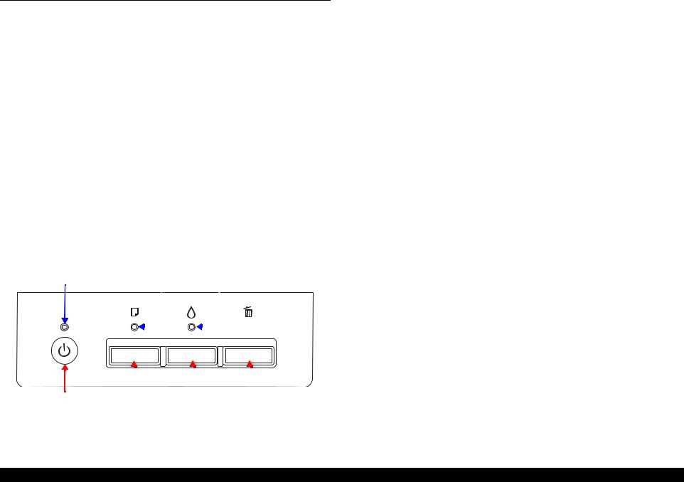
1.1 Operation Buttons & Indicators (LEDs)
1.1.1 Operation Buttons
The printer has the following four operation buttons.
|
Table 1-1. Operation Buttons |
|
|
|
|
Button |
Function |
|
Power |
Turn the power of this unit on/off. |
|
|
|
|
Paper |
In motion:Release error |
|
In Idle: Load and Eject paper |
||
|
||
|
|
|
Ink |
Start Initial Ink Charge or Head cleaning. |
|
|
|
|
Cancel |
In motion:Cancels the job execution / Release error |
|
|
|
1.1.2 Indicators (LEDs)
Three indicators (LEDs) are provided to indicate settings or printer status.
Table 1-2. Indicators (LEDs)
LED |
|
Function |
Power LED (green) |
Indicates power on/off. |
|
|
|
|
Paper LED (red) |
Indicates paper error. |
|
|
|
|
Ink LED (red) |
Light when the maintenance error occurring. |
|
|
|
|
Power LED |
Paper LED |
Ink LED |
|
|
|
|
|
|
|
|
|
|
|
|
|
|
|
|
|
|
|
|
|
|
|
|
|
|
|
|
|
|
|
|
|
|
|
|
|
|
|
|
|
|
Power Button |
Paper |
|
Button |
Ink |
|
Button Cancel |
|
Button |
|||||
|
|
|
|||||||||||
|
|
|
|||||||||||
Figure 1-1. Buttons & LEDs
1.1.3 Operation Buttons & LEDs Functions
Detailed information on the buttons and LEDs functions are listed below.
Table 1-3. Operation Button Functions
Button |
Printer |
|
Function |
|
|
||||
Status |
|
|||
|
|
|
||
|
|
|
||
Power |
Off |
Turns the power on. |
||
|
|
|
||
On |
Turns the power off. |
|||
|
||||
|
|
|
||
|
|
When the condition is Idle, Loads and Ejects the |
||
|
|
paper. |
||
|
|
When the following condition, loads the paper by |
||
|
|
pressing this key. Release the error display and |
||
|
|
continue the procedure if the paper loading is |
||
|
|
success. |
||
Paper |
On |
• |
Paper Out Error |
|
• |
Multiple Feed Error |
|||
|
|
|||
|
|
• Ink waste pad near end error |
||
|
|
When the following condition, ejects the paper by |
||
|
|
pressing this key. Release the error display and |
||
|
|
continue the procedure if the paper ejecting is |
||
|
|
success. |
||
|
|
• |
Paper jam error |
|
|
|
|
|
|
Ink |
|
Runs a head cleaning. |
||
(Press 3 seconds or |
On |
|||
Runs a Initial Ink Charge. |
||||
more) |
|
|||
|
|
|
||
|
|
|
||
Cancel |
On |
Stop printing, and cancel the job of print. |
||
When the error occurs, it cancels error release & |
||||
|
|
stops printing and ejects the paper if it exists. |
||
|
|
Print nozzle check pattern after normal Initializing |
||
Paper + Power |
On |
procedure is done. |
||
If initial ink fill is not done, execute only initial ink |
||||
|
|
|||
|
|
fill. Printer does not print nozzle check pattern. |
||
Product Description |
Operation Buttons & Indicators (LEDs) |
4 |
Confidential

L1800 |
|
|
|
|
|
Revision A |
Table 1-4. Indicators (LEDs) Function |
|
Note : |
--:No change |
|||
|
|
|
|
|
|
Flash: Repeats turning On and Off every 1.25 seconds. |
|
Indicators (LEDs) |
|
|
|||
Printer Status |
Priority*1 |
|
Flash at high speed: Repeats turning On and Off every 0.5 seconds. |
|||
Power |
Paper |
Ink |
|
|||
|
|
|
Flashes alternately 1:Same as the “Flash” |
|||
|
|
|
|
|
|
Flashes alternately 2:Repeats turning Off and On every 1.25 seconds. |
Power off (shutting down) |
Flashes at |
-- |
-- |
1 |
|
|
|
|
|||||
high speed |
|
|
||||
|
|
|
|
|
|
|
|
|
|
|
|
|
|
Firmware update (While preparing) |
-- |
-- |
-- |
2 |
|
|
|
|
|
|
|
|
|
Firmware update (Starting) |
Flashes |
OFF |
OFF |
|
|
|
|
|
|
||||
|
|
|
|
|
|
|
Fatal error |
OFF |
Flashes at |
Flashes at |
3 |
|
|
high speed |
high speed |
|
|
|||
|
|
|
|
|
||
|
|
|
|
|
|
|
Ink waste pad overflow error |
-- |
Flashes |
Flashes |
4 |
|
|
alternately 1 |
alternately 2 |
|
|
|||
|
|
|
|
|
||
|
|
|
|
|
|
|
Ink waste pad near end error |
-- |
Flashes |
Flashes |
5 |
|
|
alternately 1 |
alternately 2 |
|
|
|||
|
|
|
|
|
||
|
|
|
|
|
|
|
Paper jam error |
-- |
Flashes |
-- |
6 |
|
|
|
|
|
|
|
|
|
Initial Ink Charge Preparing |
Flashes |
-- |
OFF |
7 |
|
|
|
|
|
|
|
|
|
Initial Ink Charge Waiting |
ON |
-- |
ON |
8 |
|
|
|
|
|
|
|
|
|
Initial Ink Charging |
Flashes |
-- |
Flashes |
9 |
|
|
alternately 1 |
alternately 2 |
|
|
|||
|
|
|
|
|
||
|
|
|
|
|
|
|
Multi-feed error |
-- |
ON |
-- |
11 |
|
|
|
|
|
|
|
|
|
Paper out error |
-- |
ON |
-- |
12 |
|
|
|
|
|
|
|
|
|
Ink Sequence |
Flashes |
-- |
-- |
13 |
|
|
|
|
|
|
|
|
|
PC Printing |
Flashes |
-- |
-- |
14 |
|
|
|
|
|
|
|
|
|
Stop printing & job canceling |
Flashes |
-- |
-- |
15 |
|
|
|
|
|
|
|
|
|
Loading / Ejecting |
Flashes |
-- |
-- |
16 |
|
|
|
|
|
|
|
|
|
Power On Sequence |
Flashes |
-- |
-- |
17 |
|
|
|
|
|
|
|
|
|
Idle |
ON |
-- |
-- |
18 |
|
|
|
|
|
|
|
|
|
Reset Requirement*2 |
ON |
ON |
ON |
-- |
|
|
Note *1: When two or more errors occur at the same time, the one with higher priority will be indicated.
*2: The all LEDs light for 0.2 seconds when a reset requirement is received.
Product Description |
Operation Buttons & Indicators (LEDs) |
5 |
|
|
Confidential |
L1800 Revision A
1.1.4 Errors & Remedies
Table 1-5. Errors & Remedies
|
Error |
Occurrence terms |
How to release |
Fatal error |
|
When the unit detects an error which is impossible to work correctly. |
Turn off and restart the unit. (If occurs repeatedly, it must be repaired.) |
|
|
|
|
Ink waste pad overflow error |
When the ink waste fluid comes full. |
Turn off the unit. |
|
|
|
|
Change the absorber in the printer enclosure by a service person. and write |
|
|
|
EEPROM’s data. |
|
|
|
|
Ink waste pad near end error |
When the ink waste fluid nears full capacity. |
Press the Release error key. |
|
|
|
|
By pressing the Stop key, it cancels print data. |
|
|
|
|
Paper jam error |
When the paper loading or paper ejecting is not success. |
Remove paper and push the Release error key to continue. |
|
|
|
|
By pressing the Release error key, ejects the paper and continue the procedure if |
|
|
|
the paper ejecting is success. |
|
|
|
By pressing the Cancel key, it cancels error display and cancels print data and |
|
|
|
returns from error status. |
|
|
|
|
Paper out error |
Failure to load paper to print. |
Set paper and push the Release error key to continue. |
|
|
|
|
By pressing the Release error key, feeds the paper and continue the procedure if |
|
|
|
the paper feeding is success. |
|
|
|
By pressing the Stop key, it cancels error display and cancels print data and |
|
|
|
returns from error status. |
|
|
|
|
Multiple feed error |
When the paper is ejected without printing. |
Reset the incorrectly ejected paper and push the Release error key to continue. |
|
|
|
When the fed paper size is longer than the specified value during |
By pressing the Release error key, feeds the paper and continue the procedure if |
|
|
duplex printing. |
the paper feeding is success. |
|
|
|
By pressing the Stop key, it cancels error display and cancels print data and |
|
|
|
returns from error status. |
|
|
|
|
Note : |
For more information on the remedies, see “2.1.1 Troubleshooting according to Error Messages” (p.8). |
||
Product Description |
Operation Buttons & Indicators (LEDs) |
6 |
Confidential

C H A P T E R
2
TROUBLESHOOTING
Confidential

L1800 |
Revision A |
2.1 Overview
This chapter describes unit-level troubleshooting.
2.1.1 Troubleshooting according to Error Messages
After checking the printer LED and STM3 error indications, you can grasp the fault location using the check list in this section. When you find the fault location, refer to Chapter 3 “Disassembly and Reassembly” and change the corresponding part and/or unit. The following table indicates the check point reference tables corresponding to the error states (LED and STM3).
Table 2-1. List of Error Messages
|
Error Status |
|
LED Indications |
|
|
See the table for Troubleshooting |
|
|
Power |
Paper |
Ink |
|
|||
|
|
|
|
||||
Paper out error |
- |
Light |
|
- |
Refer to Table 2-3 “Troubleshooting of Paper Out Error” (P.11) |
||
|
|
|
|
|
|
|
|
Paper jam error |
- |
Flash |
|
- |
Refer to Table 2-4 |
“Troubleshooting of Paper Jam Error” (P.13) |
|
Multi-feed error |
- |
Light |
|
- |
Refer to Table 2-5 |
“Troubleshooting of Multi-feed error” (P.14) |
|
Maintenance request |
Off |
Flashes alternately 1 |
|
Flashes alternately 2 |
Refer to Table 2-6 |
“Troubleshooting of Maintenance Request” (P.14) |
|
|
|
|
|
|
|
|
|
Fatal error |
Off |
Flashes at high speed |
|
Flashes at high speed |
Refer to Table 2-7 |
“Troubleshooting of Fatal Error” (P.15) |
|
Note : |
--: |
No change |
|
|
|
|
|
|
Flash: |
Repeats turning On and Off every 1.25 seconds. |
|
|
|
||
|
Flash at high speed: Repeats turning On and Off every 0.5 seconds. |
|
|
|
|||
|
Flashes alternately 1: Same as the “Flash” |
|
|
|
|
|
|
|
Flashes alternately 2: Repeats turning Off and On every 1.25 seconds. |
|
|
|
|||
Troubleshooting |
Overview |
8 |
Confidential
L1800 |
|
|
|
|
|
|
|
|
Revision A |
|
|
Table 2-2. Troubleshooting of Communication Error |
|
||||||
|
|
|
|
|
|
|
|
|
|
Occurrence |
Phenomenon Detail |
Faulty Part/ |
|
Check Point |
|
|
Remedy |
||
Timing |
Part Name |
|
|
|
|||||
|
|
|
|
|
|
|
|
||
|
|
|
|
|
|
|
|
||
At power-on |
The printer does not operate at all. Panel FFC |
1. Check that the Panel FFC is connected to the Panel Board |
1. Connect the Panel FFC to the Panel Board and |
||||||
|
|
|
connector and Main Board connector CN4. |
|
|
Main Board connectors. |
|||
|
|
|
|
|
|
|
|
|
|
|
|
|
|
Panel Board |
|
|
Panel FFC |
|
|
|
|
|
|
connector |
|
|
|
|
|
|
|
|
|
|
|
|
|||
|
|
|
Panel FFC |
|
|
CN4 |
|
|
|
|
|
|
|
|
|
|
|
|
|
|
|
|
|
|
|
|
|
|
|
|
2. |
|
Check the Panel FFC for damages. |
|
|
2. |
Replace the Panel FFC with a new one. |
||
|
|
|
|
|
|
|
|
|
|
Panel Board |
1. |
|
Check the Panel Board for damages. |
|
|
1. |
Replace the Panel Board with a new one. |
||
|
|
|
|
|
|
|
|
|
|
Power Supply |
1. |
|
Check that the connector cable of the Power Supply Board is |
1. |
Connect the connector cable of the Power |
||||
Board |
|
|
connected to the Main Board connector CN60. |
|
|
|
Supply Board to the Main Board connector |
||
|
|
|
|
|
|
|
|
|
CN60. |
|
|
|
Connector cable of the |
|
|
|
|
|
|
|
|
|
Power Supply Board |
|
|
|
|
|
|
CN60
Troubleshooting |
Overview |
9 |
Confidential
L1800 |
|
|
|
|
|
|
Revision A |
|
|
Table 2-2. Troubleshooting of Communication Error |
|
||||
|
|
|
|
|
|
|
|
Occurrence |
Phenomenon Detail |
Faulty Part/ |
|
|
Check Point |
Remedy |
|
Timing |
Part Name |
|
|
||||
|
|
|
|
|
|
||
|
|
|
|
|
|
|
|
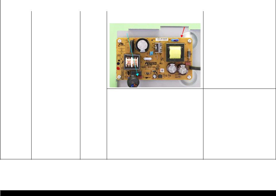
At power-on |
The printer does not operate at all. Power Supply |
2. Check that the Fuse F1 on the Power Supply Board has not |
2. Replace the Power Supply Board with a new |
||||
|
|
Board |
blown. |
one. |
|||
|
|
|
|
|
|
|
|
|
|
|
|
|
|
Power Supply Board |
|
|
|
|
|
|
|
|
|
|
|
|
|
Fuse F1 |
|
|
|
|
|
|
3. |
Check the components on the Power Supply Board for damage. |
3. |
Replace the Power Supply Board with a new |
|
|
|
|
|
|
one. |
|
|
|
|
|
|
|
At operation |
Operation at power-on is normal, Interface cable |
1. |
Check that the Interface cable is connected between the PC and |
1. |
Connect the Interface cable to the PC and |
|
|
but the error appears when the |
|
printer. |
|
printer. |
|
|
print job is sent to the printer. |
|
|
|
|
|
|
2. |
Check the Interface cable for breaking. |
2. |
Replace the Interface cable with a new one. |
||
|
|
|
||||
|
|
|
|
|
|
|
|
|
USB |
1. |
Check that the PC and printer are connected via the USB hub. |
1. |
Configure the USB ID setting. |
|
|
|
|
|
|
Refer to Chapter 4 “Adjustment”. |
|
|
|
|
|
|
|
|
|
Printer Driver |
1. |
Check that the printer driver for L1800 has already been |
1. |
Install the printer driver for L1800. |
|
|
|
|
installed. |
|
|
|
|
|
|
|
|
|
|
|
|
2. |
Check that the connected printer is L1800. |
2. |
Connect the L1800 printer. |
|
|
|
|
|
|
|
|
|
Main Board |
1. |
Check that a wrong model name has not been input to the |
1. |
Make the initial setting using the Adjustment |
|
|
|
|
EEPROM on the Main Board. |
|
Program. |
|
|
|
|
|
|
Refer to Chapter 4 “Adjustment”. |
Troubleshooting |
Overview |
10 |
Confidential
L1800 |
|
|
|
|
Revision A |
|
|
Table 2-3. Troubleshooting of Paper Out Error |
|
|
|
|
|
|
|
|
|
Occurrence |
Phenomenon Detail |
Faulty Part/ |
Check Point |
|
Remedy |
Timing |
Part Name |
|
|||
|
|
|
|
||
|
|
|
|
|
|
At operation |
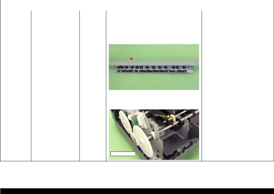
When the Paper Switch is |
ASF Assy. |
1. Check the LD Roller or Retard Roller of the ASF Assy for paper 1. |
Using a cleaning sheet, clean the LD Roller |
|
|
pressed, the LD Roller attempt to |
|
dust and foreign matter. |
and Retard Roller. The procedure is as follows. |
|
|
feed paper but the paper is not |
|
|
(1) Place the cleaning sheet upside down and |
|
|
fed. |
|
|
|
put it into the ASF Assy. |
|
|
|
|
(2) |
Press the Paper Switch to start paper feed. |
|
|
|
|
(3) |
Repeat the above steps several times. |
|
|
|
|
* To remove persistent contamination, staple |
|
|
|
|
|
|
an alcohol-dampened cloth to a postcard |
|
|
|
|
|
and clean the rollers in the following |
|
|
|
|
|
method. |
Cleaning sheet |
Postcard used |
|
as mount |
Non-adhesive part |
|
Adhesive part |
|
This side down |
Stapling |
|
|
|
Cloth damped |
|
with alcohol |
(1) Place the alcohol-dampened cloth toward the LD Roller surface of the ASF Assy.
(2) Hold the mount top end securely and press the Paper Switch.
(3) Repeat the paper feed sequence several times to clean the LD Roller surface of the ASF Assy.
Troubleshooting |
Overview |
11 |
Confidential

L1800 |
|
|
|
|
|
|
|
|
Revision A |
|
|
Table 2-3. Troubleshooting of Paper Out Error |
|
||||||
|
|
|
|
|
|
|
|
|
|
Occurrence |
Phenomenon Detail |
Faulty Part/ |
|
|
Check Point |
Remedy |
|||
Timing |
Part Name |
|
|
||||||
|
|
|
|
|
|
|
|
||
|
|
|
|
|
|
|
|
|
|
At operation |
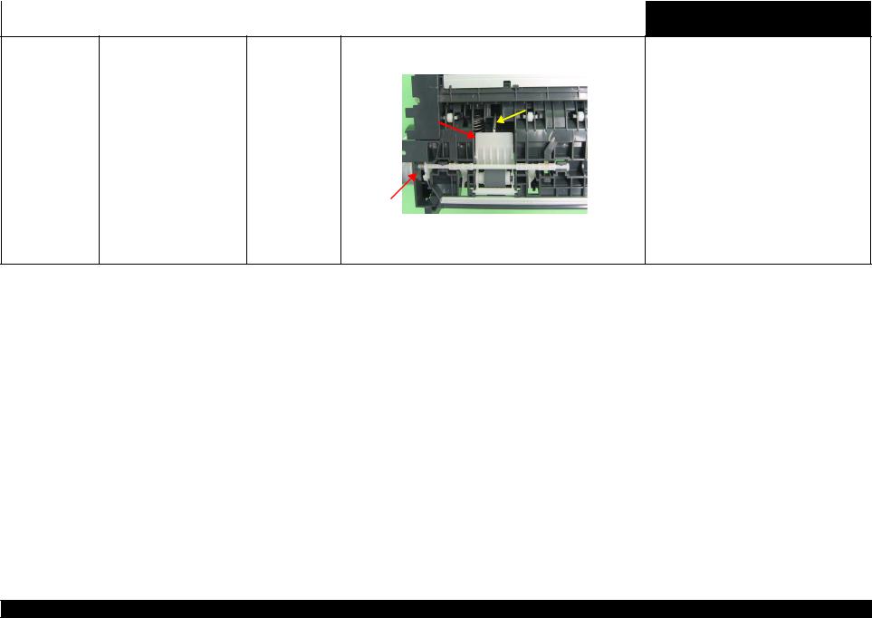
Paper Mismatch Error is |
PE Sensor |
1. Check that the connector cable of the PE Sensor is securely |
1. Connect the connector cable of the PE Sensor |
|||||
|
indicated. |
|
|
connected to the PE Sensor and Relay Board connector CN2. |
to the PE Sensor and connector CN2 on the |
||||
|
|
|
|
|
|
|
|
|
Relay Board correctly. |
|
|
|
|
PE Sensor connector |
|
|
CN2 |
|
|
2. |
Check that the Sensor Holder is mounted to the Mechanical |
2. |
Install the Sensor Holder correctly. |
||||||
|
frame correctly. |
|
|
|
|
|
|
||
|
|
|
|
|
|
|
|
|
|
|
|
|
Sensor Holder |
|
|
|
|
|
|
|
|
|
|
|
|
|
|
||
|
|
|
Detection Lever |
|
|
|
|||
|
|
|
|
|
|
|
|
|
|
|
|
|
Torsion Spring |
|
|
|
|
|
|
|
|
|
|
|
|
|
|
|
|
3. |
Move the Detection Lever manually as when the paper passes, |
3. |
Replace the PE Sensor Holder Unit with a new |
||||||
|
and check that the Detection Lever returns to the original |
|
one. |
||||||
|
position automatically by the Torsion Spring when released. |
|
|
||||||
|
Refer to the above photo. |
|
|
||||||
|
|
|
|
|
|
|
|
|
|
4. |
Using a tester, check that the PE Sensor is normal. |
4. |
Replace the PE Sensor Holder Unit with a new |
||||||
|
Paper absent |
: 2.4V or more |
|
one. |
|||||
|
Paper present |
: 0.4V or less |
|
|
|||||
Troubleshooting |
Overview |
12 |
Confidential
L1800 |
|
|
|
|
|
|
|
|
Revision A |
|
|
Table 2-4. Troubleshooting of Paper Jam Error |
|
|
|||||
|
|
|
|
|
|
|
|
|
|
Occurrence |
Phenomenon Detail |
Faulty Part/ |
|
|
|
Check Point |
|
Remedy |
|
Timing |
Part Name |
|
|
|
|
||||
|
|
|
|
|
|
|
|
||
|
|
|
|
|
|
|
|
|
|
At operation |
At the time of paper ejection, the |
– |
1. |
Check that the size of the fed paper is not larger than that of the |
1. |
Tell the user that the paper size specified by the |
|||
|
PF Roller advances the paper but |
|
|
paper specified by the driver. |
|
driver is not available for the printer. |
|||
|
cannot eject it completely. |
|
|
|
|
|
|
|
|
|
|
|
|
|
|
|
|
|
|
|
Paper is not ejected completely |
ASF Assy. |
1. |
Check that the paper is fed along the Right Edge Guide. |
1. |
Feed the paper along the Right Edge Guide. |
|||
|
and causes a jam near the Paper |
|
|
|
|
|
|
|
|
|
Paper EJ Frame |
1. |
Check that the Star Wheel Units have not come off the Paper EJ |
1. |
Securely install the Star Wheel Units to the |
||||
|
Eject Frame. |
||||||||
|
Assy. |
|
Frame Assy. |
|
Paper EJ Frame Assy. |
||||
|
|
|
|
||||||
|
|
|
|
|
|
|
|
|
|
|
|
|
|
|
Paper EJ Frame Assy. |
|
|
|
|
|
|
|
|
|
|
|
|
|
|
|
|
|
|
|
|
|
|
|
|
|
|
|
|
|
|
|
|
|
|
|
|
|
|
|
|
Star Wheel Units |
|
|
|
|
||
|
|
|
|
|
|
|
|
|
|
|
|
2. |
Check the Paper EJ Frame Assy for deformation or damages. |
2. |
Replace the Paper EJ Frame Assy with a new |
||||||
|
|
|
|
|
|
|
|
|
|
one. |
|
|
|
|
|
|
|
|
|
|
|
Spur Gear 68 |
1. |
Check the Spur Gear 68 or Spur Gear 16; B for damages. |
1. |
Replace the Front (or Rear) Paper EJ Roller |
||||||
Spur Gear 16; B |
|
|
|
|
|
|
|
|
|
Assy with a new one. |
Paper EJ Roller |
|
|
|
|
|
|
|
|
|
|
|
|
|
Spur Gear 16; B |
|
|
|
|
|
||
Assy.(front/rear) |
|
|
|
|
|
|
|
|||
|
|
|
|
|
|
|
|
|
|
|
Spur Gear 68 
Troubleshooting |
Overview |
13 |
Confidential
L1800 |
|
|
|
|
Revision A |
|
|
|
Table 2-5. Troubleshooting of Multi-feed error |
|
|
|
|
|
|
|
|
Occurrence |
Phenomenon Detail |
Faulty Part/Part |
Check Point |
Remedy |
|
Timing |
Name |
|
|||
|
|
|
|
||
|
|
|
|
|
|
Any time |
During manual double-sided |
ASF Assy |
|
printing, multiple sheets are fed |
|
|
at a time. |
|
1. Check that the Retard Roller Assy is moving properly during the 1. |
Attach the Extension Spring on the back side |
||||
feeding operation. |
of the Retard Roller Assy correctly. |
||||
|
|
|
|
|
Refer to Chapter 3 Retard Roller Assy (P.76). |
|
Bottom of |
|
|
|
|
|
the ASF Assy |
|
|
||
|
|
|
Extension Spring |
|
|
|
Retard Roller |
|
|
|
|
|
|
|
|
|
|
|
Assy |
|
|
||
|
|
|
|
|
|
|
ASF Assy |
|
|
|
|
|
|
2. Check that the position of the ASF Guide Roller LDs has been |
2. Adjust the position of the ASF Guide Roller |
||
adjusted correctly. |
LDs. |
||
|
|
|
Refer to Chapter 3 ASF Assy (P.71). |
Table 2-6. Troubleshooting of Maintenance Request
Occurrence |
Phenomenon Detail |
Faulty Part/ |
Check Point |
Remedy |
|
Timing |
Part Name |
||||
|
|
|
|||
|
|
|
|
|
|
At power-on |
At power-on, the printer does not |
Waste Ink Pads |
1. Using the Adjustment Program, check if the values of the |
1. Replace the Waste Ink Pads and reset the |
|
|
operate at all. |
|
Protection Counter A and B have exceeded the threshold value. |
Protection Counter A and B value with the |
|
|
|
|
|
Adjustment Program. |
|
|
|
|
|
|
Troubleshooting |
Overview |
14 |
Confidential

L1800 |
|
|
|
|
|
|
|
|
|
|
|
|
Revision A |
|
|
|
Table 2-7. Troubleshooting of Fatal Error |
|
|
||||||||
|
|
|
|
|
|
|
|
|
|
|
|
|
|
Occurrence |
Phenomenon Detail |
Faulty Part/ |
|
|
|
|
|
|
|
|
Check Point |
|
Remedy |
Timing |
Part Name |
|
|
|
|
|
|
|
|
|
|||
|
|
|
|
|
|
|
|
|
|
|
|
||
|
|
|
|
|
|
|
|
|
|
|
|
|
|
At power-on |
At power-on, the CR Motor does |
CR Motor |
1. |
Check the CR Motor connector cable for damages. |
1. |
Replace the CR Motor with a new one. |
|||||||
|
not operate at all. |
|
|
|
|
|
|
|
|
|
|
|
|
|
|
2. |
Check if the CR Motor operates normally. |
2. |
Replace the CR Motor with a new one. |
||||||||
|
|
|
|||||||||||
|
|
|
|
|
|
|
|
|
|
|
|
|
|
|
|
|
3. |
Check that the CR Motor connector cable is connected to the |
3. |
Connect the CR Motor connector cable to the |
|||||||
|
|
|
|
|
Main Board connector CN115. |
|
Main Board connector CN115. |
||||||
|
|
|
|
|
|
|
|
|
|
|
|
|
|
|
|
|
|
|
|
|
|
|
|
|
|
|
|
|
|
|
|
|
|
|
|
|
|
|
|
|
|
|
|
|
|
|
|
|
|
|
|
|
|
|
|
|
|
|
|
|
|
|
|
|
|
|
|
|
|
|
|
|
|
|
|
|
|
|
|
|
|
|
|
CN115
Troubleshooting |
Overview |
15 |
Confidential
L1800 |
|
|
|
|
|
Revision A |
|
|
|
|
Table 2-7. Troubleshooting of Fatal Error |
|
|
||
|
|
|
|
|
|
|
|
Occurrence |
Phenomenon Detail |
Faulty Part/ |
|
|
Check Point |
Remedy |
|
Timing |
Part Name |
|
|
|
|||
|
|
|
|
|
|
||
|
|
|
|
|
|
|
|
At power-on |
The power-on sequence is |
CR drive |
1. Check that the Carriage Shaft is lubricated with grease. |
1. Wipe the surface of the Carriage Shaft with a |
|
||
|
executed but Fatal error is |
mechanism |
|
|
|
dry, soft cloth, and lubricate the Carriage |
|
|
displayed. |
|
|
|
|
Shaft with grease G-71. |
|
|
|
|
|
Carriage Shaft |
|
Refer to Chapter 5 “Maintenance”. |
|
At power-on, the PF Motor does PF Motor |
1. Check that the connector cable of the PF Motor is connected to |
1. Connect the PF Motor connector cable to the |
not operate at all. |
the Main Board connector CN116. |
Main Board connector CN116. |
|
|
CN116 |
|
|
|
|
|
|
|
|
|
2. |
Check the PF Motor connector cable for damages. |
2. |
Replace the PF Motor with a new one. |
||
|
|
|
|
|
|
3. |
Check if the PF Motor operates normally. |
3. |
Replace the PF Motor with a new one. |
||
Troubleshooting |
Overview |
16 |
Confidential

L1800 |
|
|
|
|
|
|
|
|
|
Revision A |
|
|
|
|
Table 2-7. Troubleshooting of Fatal Error |
|
|
||||||
|
|
|
|
|
|
|
|
|
|
|
|
Occurrence |
Phenomenon Detail |
Faulty Part/ |
|
|
|
|
|
|
Check Point |
Remedy |
|
Timing |
Part Name |
|
|
|
|
|
|
|
|||
|
|
|
|
|
|
|
|
|
|
||
|
|
|
|
|
|
|
|
|
|
|
|
At power-on |
At power-on, the APG Motor |
APG Motor |
1. Check that the connector cable of the APG Motor is connected |
1. Connect the APG Motor connector cable to |
|
||||||
|
does not operate at all. |
|
|
to the Main Board connector CN118. |
the Main Board connector CN118. |
||||||
|
|
|
|
|
|
|
|
|
|
|
|
|
|
|
|
|
|
|
|
|
|
|
|
|
|
|
|
|
|
|
|
|
|
|
|
|
|
|
|
|
|
|
|
|
|
|
|
|
|
|
|
|
|
|
|
|
|
|
|
|
|
|
|
|
|
|
|
|
|
|
|
|
|
|
|
|
|
|
|
|
|
|
|
|
|
|
|
|
|
|
|
|
|
|
|
|
|
|
|
|
|
|
|
|
|
|
CN118 |
|
|
|
|
|
|
|
|
|
|
|
|
|
|
|
|
|
|
|
|
2. |
Check the APG Motor connector cable for damage. |
2. |
Replace the APG Assy with a new one. |
|||||||||
|
|
|
|
|
|
|
|
|
|
|
|
|
|
|
|
|
3. |
Check if the APG Motor operates normally. |
3. |
Replace the APG Assy with a new one. |
|||||||||
|
|
|
|
|
|
|
|
|
|
|
|
|
|
|
At power-on, the Pump Motor |
Pump Motor |
1. |
Using a tester, check the resistance value of the Pump Motor. |
1. |
If the resistance value is abnormal, replace the |
|||||||||
does not operate at all. |
|
|
Value of resistance: 10.3 ± 10% |
|
Ink System with a new one. |
|||||||||
|
|
|
|
|
|
|
|
|
|
|
|
|
|
|
|
|
2. |
Check the Pump Motor connector cable for damages. |
2. |
Replace the Ink System with a new one. |
|||||||||
|
|
|
|
|
|
|
|
|
|
|
|
|
|
|
|
|
3. |
Check that the Pump Motor connector cable is connected to the |
3. |
Connect the Pump Motor connector cable to |
|||||||||
|
|
|
Main Board connector CN117. |
|
the Main Board connector CN117. |
|||||||||
|
|
|
|
|
|
|
|
|
|
|
|
|
|
|
|
|
|
|
|
|
|
|
|
|
|
|
|
|
|
|
|
|
|
|
|
|
|
|
|
|
|
|
|
|
|
|
|
|
|
|
|
|
|
|
|
|
|
|
|
|
|
|
|
|
|
|
|
|
|
|
|
|
|
|
|
|
|
|
|
|
|
|
|
|
|
|
|
|
|
|
|
|
|
|
|
|
|
|
|
|
|
|
|
|
CN117
4. Check the Pump Motor connector cable for damages.
4. Replace the Ink System with a new one.
Troubleshooting |
Overview |
17 |
Confidential
L1800 |
|
|
|
|
|
|
Revision A |
|
|
|
|
Table 2-7. Troubleshooting of Fatal Error |
|
|
|||
|
|
|
|
|
|
|
|
|
Occurrence |
Phenomenon Detail |
Faulty Part/ |
|
Check Point |
Remedy |
|
||
Timing |
Part Name |
|
|
|||||
|
|
|
|
|
|
|
||
|
|
|
|
|
|
|
|
|
At power-on |
While the power-on sequence is |
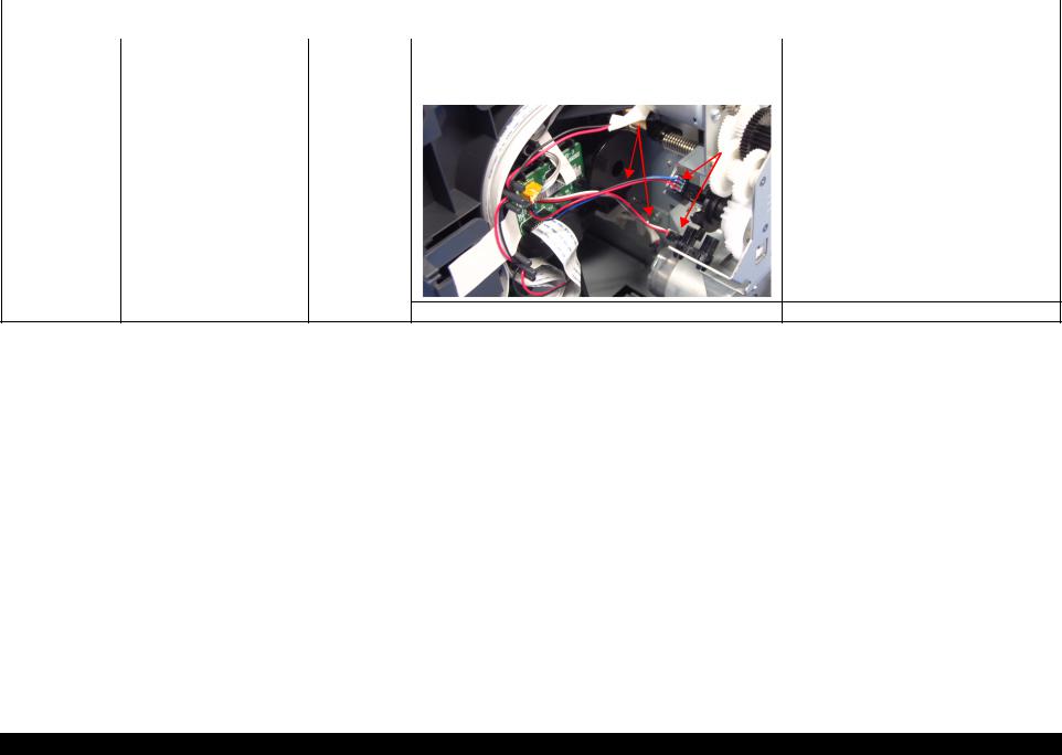
APG Sensor |
1. Check the APG Sensor connector cables is connected to the |
1. Connect the APG Sensor connector cables to |
|
|||
|
being executed, Fatal error is |
|
APG Sensor connectors. |
the APG Sensor connectors. |
||||
|
displayed. |
|
2. Check if the connector cables of the APG Sensor is broken. |
2. Replace the ASF Assy with a new ones. |
||||
|
|
|
||||||
|
|
|
|
|
|
|
|
|
|
|
|
|
APG Sensor connector cables |
|
|
|
|
|
|
|
|
|
|
|
|
|
|
|
|
|
|
APG Sensors |
|
|
|
3. Check the APG Sensors for damages. |
3. Replace the APG Assy with a new one. |
Troubleshooting |
Overview |
18 |
Confidential
L1800 |
|
|
|
|
|
Revision A |
|
|
|
|
Table 2-7. Troubleshooting of Fatal Error |
|
|
||
|
|
|
|
|
|
|
|
Occurrence |
Phenomenon Detail |
Faulty Part/ |
|
Check Point |
Remedy |
|
|
Timing |
Part Name |
|
|
||||
|
|
|
|
|
|
||
|
|
|
|
|
|
|
|
At power-on |
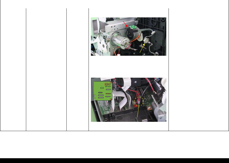
While the power-on sequence is |
ASF Motor |
1. Check that the connector cable of the ASF Motor is connected |
1. Connect the connector cable of the ASF |
|
||
|
being executed, Fatal error is |
|
to the Relay connector. |
Motor to the Relay connector. |
|||
|
displayed. |
|
|
|
|
|
|
|
|
|
|
ASF Motor |
|
|
|
|
|
|
|
|
|
|
|
Relay connector |
|
|
|
|
|
|
|
|
|
|
|
|
|
|
|
2. |
Using a tester, check the resistance value of the ASF Motor. |
2. |
If the resistance value is abnormal, replace the |
||||||||
|
|
Value of resistance: 7.0 ± 10% |
|
ASF Motor with a new one. |
|||||||
|
|
|
|
|
|
|
|
|
|
|
|
3. |
Check the ASF Motor connector cable for damages. |
3. |
Replace the ASF Motor with a new one. |
||||||||
|
|
|
|
|
|
|
|
|
|
|
|
Relay connector 1. |
Check that the Relay connector cable is connected to the Main |
1. |
Connect the Relay connector cable to the |
||||||||
cable |
Board connector CN119. |
|
Main Board connector CN119. |
||||||||
|
|
|
|
|
|
|
|
|
|
|
|
|
|
|
|
|
|
|
|
|
|
|
|
|
|
|
|
|
|
|
|
|
|
|
|
|
|
|
|
|
|
|
|
|
|
|
|
|
|
|
|
|
|
|
|
|
|
|
|
|
|
|
|
|
|
|
|
|
|
|
|
|
|
|
|
|
|
|
|
|
|
|
|
|
|
|
|
|
|
|
|
|
|
|
|
|
CN119 |
|
|
|
|
|
|
2. Check the Relay connector cable for damages. |
2. Replace the Relay connector cable with a new |
||
|
|
|
one. |
Troubleshooting |
Overview |
19 |
Confidential

L1800 |
|
|
|
|
|
|
|
Revision A |
|
|
|
|
Table 2-7. Troubleshooting of Fatal Error |
|
|
||||
|
|
|
|
|
|
|
|
|
|
Occurrence |
Phenomenon Detail |
Faulty Part/ |
|
|
Check Point |
Remedy |
|
||
Timing |
Part Name |
|
|
|
|||||
|
|
|
|
|
|
|
|
||
|
|
|
|
|
|
|
|
|
|
At power-on |
While the power-on sequence is |
Relay FFC |
1. Check that the Relay FFC is connected to the Relay Board |
1. Connect the Relay FFC to the Relay Board |
|
||||
|
being executed, Fatal error is |
|
connector CN1 and Main Board connector CN5. |
connector CN1 and Main Board connector |
|||||
|
displayed. |
|
|
|
|
|
|
CN5. |
|
|
|
|
|
|
|
|
|
|
|
|
|
|
|
CN1 |
|
|
|
|
|
|
|
|
|
|
|
|
|
|
|
|
|
|
|
|
|
Relay FFC |
|
|
|

 CN5
CN5
2. Check the Relay FFC for damages. |
2. Replace the Relay FFC cable with a new one. |
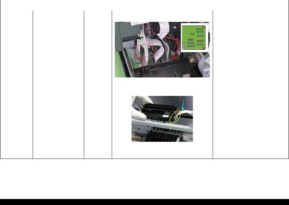
At power-on, the Carriage Unit |
CR Scale |
1. Check that the CR Scale is inserted in the slit of the CR |
1. Insert the CR Scale into the slit of the CR |
moves away from the home |
|
Encoder Sensor. |
Encoder Sensor. |
position and bumps against the |
|
|
|
right of the Frame, then hits the |
|
CR Scale |
|
left of the Frame. |
|
|
|
|
|
CR Encoder |
|
|
|
Sensor Board |
|
|
2. |
Check the CR Scale for damages and dirt. |
2. |
Wipe off the dirt completely or replace the CR |
|
|
|
|
Scale with a new one. |
|
|
|
|
|
CR Encoder |
1. |
Check the CR Encoder Sensor for paper dust, etc. |
1. |
Remove the paper dust, etc. from the CR |
Sensor Board |
|
|
|
Encoder Sensor. |
|
|
|
|
|
|
2. |
Check the CR Encoder Sensor Board for damages. |
2. |
Replace the CR Encoder Sensor Board with a |
|
|
|
|
new one. |
Troubleshooting |
Overview |
20 |
Confidential

L1800 |
|
|
|
|
|
|
|
|
|
|
|
Revision A |
|
|
|
|
Table 2-7. Troubleshooting of Fatal Error |
|
|
||||||||
|
|
|
|
|
|
|
|
|
|
|
|
|
|
Occurrence |
Phenomenon Detail |
Faulty Part/ |
Check Point |
Remedy |
|
||||||||
Timing |
Part Name |
|
|||||||||||
|
|
|
|
|
|
|
|
|
|
|
|
||
|
|
|
|
|
|
|
|
|
|
|
|
|
|
At power-on |
At power-on, the Carriage Unit |
Sensor FFC |
1. Check that the Sensor FFC is connected to the CR Encoder |
1. Connect the Sensor FFC to the CR Encoder |
|
||||||||
|
moves away from the home |
|
Sensor Board connector and Main Board connector CN9. |
Sensor Board connector and Main Board |
|||||||||
|
position and bumps against the |
|
|
|
|
|
|
|
|
|
|
connector CN9. |
|
|
right of the Frame, then hits the |
|
|
|
|
|
|
|
|
|
|
|
|
|
left of the Frame. |
|
|
|
|
|
|
|
|
|
|
|
|
|
|
|
|
|
|
|
|
|
|
|
|
|
|
|
|
|
|
|
|
|
|
|
|
|
|
|
|
|
|
|
|
|
|
|
|
|
|
|
|
|
|
|
|
|
|
|
|
|
|
|
|
|
|
|
|
|
|
|
|
|
|
|
|
|
|
|
|
|
|
|
|
|
|
|
|
|
|
|
|
|
|
|
|
|
|
|
|
|
|
|
|
|
|
|
|
|
|
|
|
|
|
|
|
|
|
|
|
|
|
|
|
|
|
|
|
CR Encoder Sensor |
|
|
|
|
|
|
|
|
|
|
|
Board connector |
|
|
|
CN9 |
|
|
|
|
|
|
|
|
|
|
|
|
|
|
|
|
|
|
|
|
|
|
|
|
|
|
|
|
|
2. |
Check the Sensor FFC for damages. |
|
|
|
|
2. |
Replace the Sensor FFC with a new one. |
||
|
|
|
|
|
|
|
|
|
|
|
|
At power-on, the PF Roller |
PF Encoder |
1. |
Check that the PF Encoder Sensor Holder is mounted correctly. |
1. |
Install the PF Encoder Sensor Holder |
||||||
rotates fast about a half turn. |
Sensor Holder |
|
|
|
|
|
|
|
|
|
correctly. |
|
|
|
|
|
|
|
|
|
|
|
|
|
|
2. |
Check that the FFC of the PF Encoder Sensor is securely |
2. |
Connect the PF Encoder Sensor FFC to the PF |
||||||
|
|
|
connected to the PF Encoder Sensor Board connector and Relay |
|
Encoder Sensor Board and Relay Board |
||||||
|
|
|
Board connector CN6. |
|
|
|
|
|
connector CN6. |
||
|
|
|
|
|
|
|
|
|
|
||
|
|
|
|
|
|
CN6 |
|
|
|
|
|
|
PF Encoder Sensor |
|
|
|
|
Board connector |
|
|
|
|
|
|
|
|
|
|
|
|
|
3. Check the PF Encoder Sensor for paper dust, etc. |
3. |
Remove the paper dust, etc. from the PF |
||
|
|
|
|
Encoder Sensor. |
|
|
|
|
|
4. Check if the PF Encoder or the FFC is damaged. |
4. |
Replace the PF Encoder with a new one. |
||
Troubleshooting |
Overview |
21 |
Confidential

L1800 |
|
|
|
Revision A |
|
|
|
|
Table 2-7. Troubleshooting of Fatal Error |
|
|
|
|
|
|
|
|
Occurrence |
Phenomenon Detail |
Faulty Part/ |
Check Point |
Remedy |
|
Timing |
Part Name |
|
|||
|
|
|
|
||
|
|
|
|
|
|
At power-on |
At power-on, the PF Roller |
PF Scale |
1. Check that the PF Scale is inserted in the slit of the PF Encoder |
1. Install the PF Scale in the slit of the PF |
|
|
rotates fast about a half turn. |
|
Sensor. |
Encoder Sensor correctly. |
|
PF Scale |
Slit |
|
|
|
2. |
Check the PF Scale for damages and dirt. |
2. |
Replace the PF Scale with a new one. |
||||||||
|
|
|
|
|
|
|
|
|
|
|
|
|
|
|
During printing |
After receiving a print data, an |
Head FFC |
1. |
Check that the Head FFC and the Sensor FFC are securely |
1. |
Connect the Head FFC and the Sensor FFC to |
||||||||
|
error is displayed on the LED |
Sensor FFC |
|
connected to the Main Board connectors CN9, CN12, CN13, |
|
the Main Board connectors CN9, CN12, |
||||||||
|
and STM3. |
|
|
and CN14. |
|
CN13, and CN14. |
||||||||
|
|
|
|
|
|
|
|
|
|
|
|
|
|
|
|
|
|
|
|
|
|
|
|
|
|
|
|
|
|
|
|
|
|
|
|
|
|
|
|
|
|
|
|
|
|
|
|
|
|
|
|
|
|
|
|
|
|
|
|
|
|
|
|
|
|
|
|
|
|
|
|
|
|
|
|
|
|
|
|
|
|
|
|
|
|
|
|
|
|
|
|
|
|
|
|
|
|
|
|
|
|
|
|
|
|
|
|
|
|
|
|
|
|
|
|
|
|
|
|
|
|
|
|
|
|
|
|
|
|
|
|
|
|
|
|
|
|
|
|
|
|
|
|
|
|
|
|
|
|
|
|
|
|
|
|
|
|
|
|
|
|
|
|
|
 CN9, CN12, CN13, CN14
Troubleshooting |
Overview |
22 |
Confidential
L1800 |
|
|
|
Revision A |
|
|
|
|
Table 2-7. Troubleshooting of Fatal Error |
|
|
|
|
|
|
|
|
Occurrence |
Phenomenon Detail |
Faulty Part/ |
Check Point |
Remedy |
|
Timing |
Part Name |
|
|||
|
|
|
|
||
|
|
|
|
|
|
During printing |
After starting to print, ink is not |
Head FFC |
1. Check that the Head FFC is securely connected to the Main |
1. Connect the Head FFC to the Main Board |
|
|
ejected and paper stops midway. |
|
Board connectors CN12, CN13, and CN14. |
connectors CN12, CN13, and CN14. |
|
|
|
|
|
|
|
|
|
|
|
|
|
|
|
|
|
|
|
|
|
|
|
|
|
|
|
|
|
|
|
|
|
|
|
|
|
|
|
|
|
|
|
|
|
|
|
|
|
|
|
|
|
|
|
|
|
|
|
|
|
|
|
|
|
|
|
|
|
|
|
|
|
|
|
|
|
|
|
|
|
|
|
|
|
|
|
|
|
|
|
|
|
|
|
|
|
|
|
|
|
|
|
|
|
|
|
|
|
|
|
|
|
|
|
|
|
|
|
|
|
|
|
|
|
|
|
|
|
|
|
|
|
|
|
|
|
|
|
|
|
|
|
|
|
|
|
|
|
|
|
|
|
|
|
|
|
|
|
|
|
|
|
|
|
|
|
|
|
|
|
|
|
|
|
|
|
|
|
|
|
|
|
|
|
|
|
|
|
|
|
|
|
|
|
|
|
|
|
|
|
|
|
|
|
|
|
|
|
|
|
|
|
|
|
|
|
|
|
|
CN12, CN13, CN14 |
|
|
|
|
|
|
|
|||||||
|
|
|
|
|
|
|
|
|
|
|
|
|
|
|
|
|
|
|
2. |
Check the Head FFC for damages. |
2. |
Replace the Head FFC with a new one. |
|||||||||||||
|
|
|
|
|
|
|
|
|
|
|
|
|
|
|
|
|
|
Head FFC |
1. |
Check that the Head FFC is securely connected to the Print |
1. |
Connect the Head FFC to the CR Relay Board |
|||||||||||||
|
|
Head connectors. |
|
|
connectors CN1 and CN2. |
||||||||||||
|
|
|
|
|
|
|
|
2. |
Connect the Head FFC to the Print Head |
||||||||
|
|
|
|
|
Head FFC |
|
|
|
|
|
|||||||
|
|
|
|
|
|
|
|
|
|
|
|
|
|
|
|
|
connectors. |
|
|
|
|
|
|
|
|
|
|
|
|
|
|
|
|
|
|
|
|
|
|
Print Head |
|
|
|
|
|
|
Connector |
|
|
|
|
|
|
|
|
|
|
|
2. |
Check the Head FFC for damages. |
3. |
Replace the Head FFC with a new one. |
|
|
|
|
|
|
|
|
Ink is not ejected from most |
Print Head |
1. |
Check for occurrence of Head Hot. |
1. |
Replace the Print Head with a new one. |
|
nozzles. |
|
|
|
|
|
|
Troubleshooting |
Overview |
23 |
Confidential

L1800 |
Revision A |
2.1.2 Troubleshooting based on Observed Faults
This section provides troubleshooting procedures based on observed faults such as print quality troubles and abnormal noise.
Table 2-8. Print Quality Troubles
Observed Faults |
Details of the Fault |
Faulty Part/ |
|
Check Point |
Remedy |
||
Part Name |
|
||||||
|
|
|
|
|
|
|
|
|
|
|
|
|
|
|
|
Dot missing and |
Inks are not ejected from the |
Ink System Unit |
1. Check for foreign matter around the Seal Rubber on the Cap |
1. Remove the foreign matter around the Seal |
|||
mixed colors |
Print Head to the Cap. |
(Cap) |
Unit. |
Rubber completely. |
|||
|
|
|
|
|
|
|
|
|
|
|
|
Seal Rubbers |
|
|
|
|
|
|
|
|
|
|
|
|
|
|
|
|
|
|
|
|
|
|
Extension Spring, 1.19 IS |
|
|
|
|
|
|
|
|
|
|
|
|
|
2. |
Check that the Extension Spring 1.19 IS is correctly installed to |
2. |
Replace the Ink System Unit with a new one. |
|||
|
|
the Cap Unit. |
|
|
|||
|
|
|
|
|
|
|
|
Although inks are ejected from Print Head |
1. |
Run a Nozzle Check, and check the printed pattern if it has |
1. |
After running a Head Cleaning, check the |
|||
the Print Head to the Cap, the |
|
broken lines or missing segments. |
|
Nozzle Check Pattern again. |
|||
trouble still occurs after |
|
|
|
|
|
|
|
executing a cleaning cycle. |
|
|
|
|
|
|
|
Troubleshooting |
Overview |
24 |
Confidential
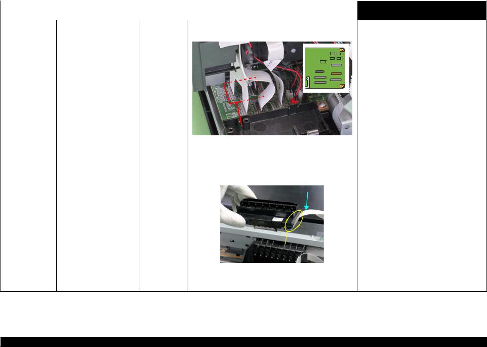
L1800 |
|
|
|
|
|
|
|
|
|
|
|
|
|
Revision A |
|
|
|
|
Table 2-8. Print Quality Troubles |
|
|||||||||||
|
|
|
|
|
|
|
|
|
|
|
|
|
|
|
|
Observed Faults |
Details of the Fault |
Faulty Part/ |
Check Point |
Remedy |
|||||||||||
Part Name |
|||||||||||||||
|
|
|
|
|
|
|
|
|
|
|
|
|
|
||
|
|
|
|
|
|
|
|
|
|
|
|
|
|
||
Dot missing and |
Although inks are ejected from Head FFC |
1. Check that the Head FFC is securely connected to the Main |
1. Connect the Head FFC to the Main Board |
||||||||||||
mixed colors |
the Print Head to the Cap, the |
|
Board connectors CN12, CN13, and CN14. |
connectors CN12, CN13, and CN14. |
|||||||||||
|
trouble still occurs after |
|
|
|
|
|
|
|
|
|
|
|
|
|
|
|
executing a cleaning cycle. |
|
|
|
|
|
|
|
|
|
|
|
|
|
|
|
|
|
|
|
|
|
|
|
|
|
|
|
|
|
|
|
|
|
|
|
|
|
|
|
|
|
|
|
|
|
|
|
|
|
|
|
|
|
|
|
|
|
|
|
|
|
|
|
|
|
|
|
|
|
|
|
|
|
|
|
|
|
|
|
|
|
|
|
|
|
|
|
|
|
|
|
|
|
|
|
|
|
|
|
|
|
|
|
|
|
|
|
|
|
|
|
|
|
|
|
|
|
|
|
|
|
|
|
|
|
|
|
|
|
|
|
|
|
|
|
|
|
|
|
|
|
|
|
|
|
CN12, CN13, CN14 |
|
|
|
|
|
|
|
|
|
|
|
|
|
|
|
2. |
Check the Head FFC for damages. |
2. |
Replace the Head FFC with a new one. If the |
||||
|
|
|
|
|
|
|
|
trouble still occurs after replacing it, replace the |
|
|
|
|
|
|
|
|
Print Head with a new one. |
|
|
|
|
|
|
|
|
|
Head FFC |
1. |
Check that the Head FFC is securely connected to the Print Head |
1. |
Connect the Head FFC to the CR Relay Board |
||||
|
|
connectors. |
|
connectors CN1 and CN2. |
||||
|
|
|
|
|
|
|
2. |
Connect the Head FFC to the Print Head |
|
|
|
|
|
Head FFC |
|
||
|
|
|
|
|
|
|
connectors. |
|
|
|
|
|
|
|
|
|
|
|
Print Head |
|
|
Connector |
|
|
|
|
2. Check the Head FFC for damages. |
3. Replace the Head FFC with a new one. If the |
|
|
|
trouble still occurs after replacing it, replace the |
|
|
Print Head with a new one. |
Troubleshooting |
Overview |
25 |
Confidential
 Loading...