


MP45A4
Table of contents
 Loading...
Emerson MP45A4, MP45A5, MP105A5, MP155A4, MP155A5 User Manual
...
User Guide
Mentor MP
High performance DC drive
25A to 7400A, 480V to 690V
Two or four quadrant operation
Part Number: 0476-0000-03
Issue: 3
www.controltechniques.com

General Information
The manufacturer accepts no liability for any consequences resulting from inappropriate, negligent or incorrect
installation or adjustment of the optional operating parameters of the equipment or from mismatching the variable speed
drive with the motor.
The contents of this guide are believed to be correct at the time of printing. In the interests of a commitment to a policy
of continuous development and improvement, the manufacturer reserves the right to change the specification of the
product or its performance, or the contents of the guide, without notice.
All rights reserved. No parts of this guide may be reproduced or transmitted in any form or by any means, electrical or
mechanical including photocopying, recording or by an information storage or retrieval system, without permission in
writing from the publisher.
Drive software version
This product is supplied with the latest software version. If this drive is to be connected to an existing system or machine,
all drive software versions should be verified to confirm the same functionality as drives of the same model already
present. This may also apply to drives returned from a Control Techniques Service Centre or Repair Centre. If there is
any doubt please contact the supplier of the product.
The software version of the drive can be checked by looking at Pr 11.29 (di14/0.49) and Pr 11.34. This takes the form
of xx.yy.zz where Pr 11.29 (di14/0.49) displays xx.yy and Pr 11.34 displays zz. (e.g. for software version 01.01.00,
Pr 11.29 (di14/0.49) = 1.01 and Pr 11.34 displays 0).
Environmental statement
Control Techniques is committed to minimising the environmental impacts of its manufacturing operations and of its
products throughout their life cycle. To this end, we operate an Environmental Management System (EMS) which is
certified to the International Standard ISO 14001. Further information on the EMS, our Environmental Policy and other
relevant information is available on request, or can be found at www.greendrives.com.
The electronic variable-speed drives manufactured by Control Techniques have the potential to save energy and
(through increased machine/process efficiency) reduce raw material consumption and scrap throughout their long
working lifetime. In typical applications, these positive environmental effects far outweigh the negative impacts of product
manufacture and end-of-life disposal.
Nevertheless, when the products eventually reach the end of their useful life, they must not be discarded but should
instead be recycled by a specialist recycler of electronic equipment. Recyclers will find the products easy to dismantle
into their major component parts for efficient recycling. Many parts snap together and can be separated without the use
of tools, while other parts are secured with conventional fasteners. Virtually all parts of the product are suitable for
recycling.
Product packaging is of good quality and can be re-used. Large products are packed in wooden crates, while smaller
products come in strong cardboard cartons which themselves have a high recycled fibre content. If not re-used, these
containers can be recycled. Polythene, used on the protective film and bags for wrapping product, can be recycled in the
same way. Control Techniques' packaging strategy prefers easily-recyclable materials of low environmental impact, and
regular reviews identify opportunities for improvement.
When preparing to recycle or dispose of any product or packaging, please observe local legislation and best practice.
REACH legislation
EC Regulation 1907/2006 on the Registration, Evaluation, Authorisation and restriction of Chemicals (REACH) requires
the supplier of an article to inform the recipient if it contains more than a specified proportion of any substance which is
considered by the European Chemicals Agency (ECHA) to be a Substance of Very High Concern (SVHC) and is
therefore listed by them as a candidate for compulsory authorisation.
For current information on how this requirement applies in relation to specific Control Techniques products, please
approach your usual contact in the first instance. Control Techniques position statement can be viewed at:
http://www.controltechniques.com/REACH
Copyright © April 2010 Control Techniques Ltd
Issue Number: 3
Software: 01.05.00 onwards

Contents
1 Safety Information .................................5
1.1 Warnings, Cautions and Notes .............................5
1.2 Electrical safety - general warning ........................5
1.3 System design and safety of personnel ................5
1.4 Environmental limits ..............................................5
1.5 Access ..................................................................5
1.6 Fire protection .......................................................5
1.7 Compliance with regulations .................................5
1.8 Motor .....................................................................5
1.9 Adjusting parameters ............................................5
1.10 Electrical installation .............................................5
2 Product information ..............................6
2.1 Ratings ..................................................................6
2.2 Model number .......................................................7
2.3 Compatible encoders ............................................8
2.4 Nameplate description ..........................................8
2.5 Drive features and options ....................................9
2.6 Items supplied with the drive ...............................12
3 Mechanical Installation .......................13
3.1 Safety ..................................................................13
3.2 Planning the installation ......................................13
3.3 Terminal cover removal ......................................14
3.4 Mounting method ................................................17
3.5 Installing and removing the terminal shrouds .....24
3.6 Enclosure ............................................................26
3.7 Heatsink fan operation ........................................27
3.8 IP rating (Ingress Protection) ..............................27
3.9 Electrical terminals ..............................................28
3.10 Routine maintenance ..........................................31
4 Electrical installation ..........................32
4.1 Electrical connections .........................................33
4.2 Ground connections ............................................35
4.3 AC supply requirements ......................................36
4.4 Line reactors .......................................................37
4.5 Control 24Vdc supply ..........................................37
4.6 Cable and fuse size ratings .................................38
4.7 External suppressor resistor ...............................44
4.8 Ground leakage ..................................................46
4.9 EMC (Electromagnetic compatibility) ..................46
4.10 Serial communications connections ....................48
4.11 Shield connections ..............................................49
4.12 Connecting the fan on size 2C and 2D drives .....49
4.13 Control connections ............................................50
4.14 General ...............................................................51
4.15 Connecting an encoder .......................................54
5 Getting started .....................................56
5.1 Understanding the display ..................................56
5.2 Keypad operation ................................................56
5.3 Menu 0 (sub block) .............................................58
5.4 Pre-defined sub blocks .......................................59
5.5 Menu 0 (linear) ....................................................60
5.6 Menu structure ....................................................60
5.7 Advanced menus ................................................61
5.8 Saving parameters ..............................................61
5.9 Restoring parameter defaults ..............................61
5.10 Differences between European and
USA defaults .......................................................62
5.11 Displaying parameters with non-default
values only ..........................................................62
5.12 Displaying destination parameters only ..............62
5.13 Parameter access level and security ..................62
5.14 Serial communications ........................................63
6 Basic parameters ................................64
6.1 Full descriptions ..................................................65
7 Running the motor ..............................72
7.1 Quick start commissioning / start-up (from
European defaults) ..............................................73
7.2 Quick start commissioning / start-up (from USA
defaults) ..............................................................75
7.3 CTSoft software commissioning / start-up tool ....76
7.4 Setting up a feedback device ..............................77
8 Optimization .........................................78
8.1 Armature current .................................................78
8.2 Speed feedback ..................................................78
8.3 Field current ........................................................78
8.4 Current loop gains self-tuning .............................78
8.5 Speed loop gains tuning .....................................79
8.6 Current limit tapers ..............................................80
9 SMARTCARD operation ......................81
9.1 Introduction .........................................................81
9.2 Easy saving and reading .....................................81
9.3 Transferring data .................................................81
9.4 Data block header information ............................83
9.5 SMARTCARD parameters ..................................83
9.6 SMARTCARD trips .............................................84
10 Onboard PLC .......................................86
10.1 Onboard PLC and SYPT Lite ..............................86
10.2 Benefits ...............................................................86
10.3 Limitations ...........................................................86
10.4 Getting started ....................................................87
10.5 Onboard PLC parameters ...................................87
10.6 Onboard PLC trips ..............................................88
10.7 Onboard PLC and the SMARTCARD .................88
Mentor MP User Guide 3
Issue : 3 www.controltechniques.com

11 Advanced parameters .........................89
11.1 Menu 1: Speed reference ....................................94
11.2 Menu 2: Ramps ...................................................98
11.3 Menu 3: Speed feedback and speed control .....101
11.4 Menu 4: Torque and current control ..................104
11.5 Menu 5: Motor and field control .........................108
11.6 Menu 6: Sequencer and clock ...........................112
11.7 Menu 7: Analog I/O ...........................................114
11.8 Menu 8: Digital I/O ............................................116
11.9 Menu 9: Programmable logic, motorized pot and
binary sum .........................................................120
11.10 Menu 10: Status and trips .................................123
11.11 Menu 11: General drive set-up ..........................124
11.12 Menu 12: Threshold detectors, variable selectors
and brake control function .................................125
11.13 Menu 13: Position control ..................................130
11.14 Menu 14: User PID controller ............................134
11.15 Menus 15, 16 and 17: Solutions Module slots ..137
11.16 Menu 18: Application menu 1 ............................138
11.17 Menu 19: Application menu 2 ............................138
11.18 Menu 20: Application menu 3 ............................138
11.19 Menu 21: Second motor parameters .................139
11.20 Menu 22: Additional Menu 0 set-up ..................139
11.21 Menu 23: Header selections .............................139
11.22 Advanced features ............................................140
12 Technical data ....................................145
12.1 Drive technical data ...........................................145
12.2 Cable and fuse size ratings ...............................151
12.3 Optional external EMC filters ............................166
13 Diagnostics ........................................167
13.1 Trip indications ..................................................167
13.2 Trip indications ..................................................167
13.3 Trip categories ..................................................174
13.4 Alarm indications ...............................................175
13.5 Status indications ..............................................175
13.6 Displaying the trip history ..................................175
13.7 Behaviour of the drive when tripped ..................175
13.8 Trip masking ......................................................175
14 UL information ...................................176
14.1 Common UL Information ...................................176
14.2 AC supply specification .....................................176
14.3 Maximum continuous output current .................176
14.4 Safety label .......................................................176
14.5 UL Listed accessories .......................................176
4 Mentor MP User Guide
www.controltechniques.com Issue: 3

Safety
WARNING
CAUTION
NOTE
Information
Product
information
Mechanical
Installation
Electrical
installation
Getting
started
Basic
parameters
Running the
motor
Optimization
SMARTCARD
operation
Onboard
PLC
Advanced
parameters
Technical
data
Diagnostics
UL
information
1 Safety Information
1.1 Warnings, Cautions and Notes
A Warning contains information which is essential for
avoiding a safety hazard.
A Caution contains information which is necessary for
avoiding a risk of damage to the product or other equipment.
A Note contains information which helps to ensure correct operation of
the product.
1.2 Electrical safety - general warning
The voltages used in the drive can cause severe electrical shock and/or
burns, and could be lethal. Extreme care is necessary at all times when
working with or adjacent to the drive.
Specific warnings are given at the relevant places in this Guide.
1.3 System design and safety of
The drive is intended as a component for professional incorporation into
complete equipment or system. If installed incorrectly, the drive may
present a safety hazard.
The drive uses high voltages and currents, carries a high level of stored
electrical energy, and is used to control equipment which can cause
injury.
System design, installation, commissioning / start-up and maintenance
must be carried out by personnel who have the necessary training and
experience. They must read this safety information and this guide
carefully.
The STOP and START controls or electrical inputs of the drive must
not be relied upon to ensure safety of personnel. They do not
isolate dangerous voltages from the output of the drive or from any
external option unit. The supply must be disconnected by an
approved electrical isolation device before gaining access to the
electrical connections.
The drive is not intended to be used for safety-related functions.
Careful consideration must be given to the function of the drive which
might result in a hazard, either through its intended behaviour or through
incorrect operation due to a fault. In any application where a malfunction
of the drive or its control system could lead to or allow damage, loss or
injury, a risk analysis must be carried out, and where necessary, further
measures taken to reduce the risk - for example, an over-speed
protection device in case of failure of the speed control, or a fail-safe
mechanical brake in case of loss of motor braking.
personnel
1.4 Environmental limits
Instructions within the supplied data and information within the Mentor
MP User Guide regarding transport, storage, installation and the use of
the drive must be complied with, including the specified environmental
limits. Drives must not be subjected to excessive physical force.
1.5 Access
Access must be restricted to authorized personnel only. Safety
regulations which apply at the place of use must be complied with.
1.6 Fire protection
The drive enclosure is not classified as a fire enclosure. A separate fire
enclosure must be provided.
1.7 Compliance with regulations
The installer is responsible for complying with all relevant regulations,
such as national wiring regulations, accident prevention regulations and
electromagnetic compatibility (EMC) regulations. Particular attention
must be given to the cross-sectional areas of conductors, the selection
of fuses and other protection, and protective ground (earth) connections.
The Mentor MP User Guide contains instructions for achieving
compliance with specific EMC standards.
Within the European Union, all machinery in which this product is used
must comply with the following directives:
2006/42/EC: Safety of machinery
2004/108/EC: Electromagnetic compatibility
1.8 Motor
Ensure the motor is installed in accordance with the manufacturer's
recommendations. Ensure the motor shaft is not exposed.
Low speeds may cause the motor to overheat because the cooling fan
becomes less effective. The motor should be installed with a protection
thermistor. If necessary, an electric forced ventilation fan should be
used.
The values of the motor parameters set in the drive affect the protection
of the motor. The default values in the drive should not be relied upon.
It is essential that the correct value is entered into Pr 5.07 (SE07, 0.28),
Motor rated current. This affects the thermal protection of the motor.
1.9 Adjusting parameters
Some parameters have a profound effect on the operation of the drive.
They must not be altered without careful consideration of the impact on
the controlled system. Measures must be taken to prevent unwanted
changes due to error or tampering.
1.10 Electrical installation
1.10.1 Electric shock risk
The voltages present in the following locations can cause severe electric
shock and may be lethal:
• AC supply cables and connections
• Output cables and connections
• Many internal parts of the drive, and external option units
Unless otherwise indicated, control terminals are single insulated and
must not be touched.
1.10.2 Stored charge
The drive contains capacitors that remain charged to a potentially lethal
voltage after the AC supply has been disconnected. If the drive has been
energized, the AC supply must be isolated at least ten minutes before
work may continue.
Mentor MP User Guide 5
Issue: 3 www.controltechniques.com

Safety
NOTE
Information
Product
information
Mechanical
Installation
Electrical
installation
Getting
started
Basic
parameters
Running the
motor
Optimization
SMARTCARD
operation
Onboard
PLC
Advanced
parameters
Technical
data
Diagnostics
UL
information
2 Product information
Table 2-1 Model to frame size cross reference
Model
480V
EN/IEC
cULus
MP25A4(R) MP25A5(R)
MP75A4(R) MP75A5(R)
MP105A4(R) MP105A5(R)
MP210A4(R) MP210A5(R)
MP350A4(R) MP350A5(R) MP350A6(R)
MP420A4(R)
MP550A4(R)
MP700A4(R) MP700A5(R) MP700A6(R)
MP900A4(R)
MP1200A4 MP1200A5 MP1200A6
MP1850A4 MP1850A5 MP1850A6
MP1200A4R MP1200A5R MP1200A6R
MP1850A4R MP1850A5R MP1850A6R
2.1 Ratings
The power ratings for the 480V, 575V and 690V configurations are
shown in Table 2-2, Table 2-3 and Table 2-4.
The continuous current ratings given are for a maximum ambient
temperature of 40°C (104°F) and an altitude of 1000m. For operation at
higher temperatures and altitudes de-rating is required.
For further information see Chapter 12 Technical data on page 145.
Table 2-2 480V current ratings
AC input
current
Model
MP25A4(R) 22 25 37.5 9 15
MP45A4(R) 40 45 67.5 15 27
MP75A4(R) 67 75 112.5 27 45
MP105A4(R) 94 105 157.5 37.5 60
MP155A4(R) 139 155 232.5 56 90
MP210A4(R) 188 210 315 75 125
MP350A4(R) 313 350 525 125 200
MP420A4(R) 376 420 630 150 250
MP550A4(R) 492 550 825 200 300
MP700A4(R) 626 700 1050 250 400
MP825A4(R) 738 825 1237.5 300 500
MP900A4(R) 805 900 1350 340 550
MP1200A4(R) 1073 1200 1800 450 750
MP1850A4(R) 1655 1850 2775 700 1150
Continuous Continuous
575V
EN/IEC
cULus to 600V
690V
EN/IEC
Frame
1AMP45A4(R) MP45A5( R)
1BMP155A4(R) MP155A5(R)
MP470A5(R) MP470A6(R)
2A
2BMP825A4(R) MP825A5(R) MP825A6(R)
2C
2D
DC output current
150%
overload
AAAkWhp
Typ i cal m otor
power
@
400Vdc@ 500Vdc
Table 2-3 575V current ratings
AC input
current
Model
MP25A5(R) 22 25 37.5 14 18
MP45A5(R) 40 45 67.5 25 33
MP75A5(R) 67 75 112.5 42 56
MP105A5(R) 94 105 157.5 58 78
MP155A5(R) 139 155 232.5 88 115
MP210A5(R) 188 210 315 120 160
MP350A5(R) 313 350 525 195 260
MP470A5(R) 420 470* 705 265 355
MP700A5(R) 626 700 1050 395 530
MP825A5(R) 738 825* 1237.5 465 620
MP1200A5(R) 1073 1200 1800 680 910
MP1850A5(R) 1655 1850 2775 1045 1400
Continuous Continuous
AAAkWhp
DC output current
150%
overload
Typ i cal m oto r
power
(With Vdc =
630V)
* For this rating at 575V, 150% overload time is 20s at 40°C and 30s at
35°C.
Table 2-4 690V current ratings
AC input
current
Model
MP350A6(R) 313 350 525 240 320
MP470A6(R) 420 470* 705 320 425
MP700A6(R) 626 700 1050 480 640
MP825A6(R) 738 825* 1237.5 650 850
MP1200A6(R) 1073 1200 1800 850 1150
MP1850A6(R) 1655 1850 2775 1300 1750
Continuous Continuous
AAAkWhp
DC output Current
150%
Overload
Typ i cal m otor
power (With
Vdc = 760V)
* For this rating at 690V, 150% overload time is 20s at 40°C and 30s at
35°C.
Maximum continuous input current
The values of maximum continuous input current are given to aid the
selection of cables and fuses. These values are stated for worst-case
condition.
For current ratings above 1850A then parallel connection of the drives is
required. However, this function is not implemented on firmware
versions V01.05.00 and earlier.
6 Mentor MP User Guide
www.controltechniques.com Issue: 3
Safety
100
105
110
115
120
125
130
135
140
145
150
155
160
0
10
20
30
40
50
60
70
80
90
100
110
120
130
140
150
160
170
180
200
overload duration (seconds)
overload
(%)
NOTE
Mentor product line
MP
:
Continuous armature current rating (A)
Vol t age r a t ing
4 = 480V 24V to 480V -20% +10%
5 = 575V 500V to 575V -10% +10%
6 = 690V 500V to 690V -10% +10%
Mentor Platform
MP 2 0 01 4 R
R
Blank
-
4 quadrant operation
- 2 quadrant operation
A
Information
Product
information
Mechanical
Installation
Electrical
installation
Getting
started
Basic
parameters
Running the
motor
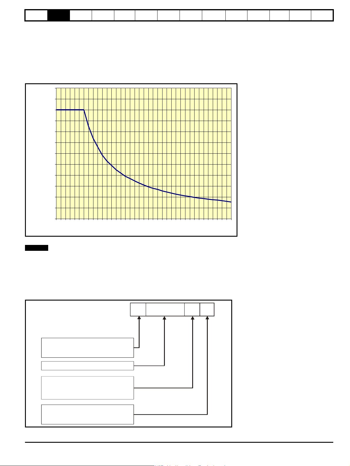
2.1.1 Typical short-term overload limits
The maximum percentage overload limit changes depending on the
selected motor.
Variations in motor rated current will result in changes in the maximum
possible overload as detailed in the Mentor MP Advanced User Guide.
Figure 2-1 can be used to determine the maximum overload duration
available for overloads between 100% and 150%. For example the
maximum overload available for a period of 60 seconds is 124%.
Figure 2-1 Maximum overload duration available
Optimization
SMARTCARD
operation
Onboard
PLC
Advanced
parameters
Technical
data
Diagnostics
UL
information
Overload of 150% for 30s is available up to a maximum of 10 repetitions
per hour.
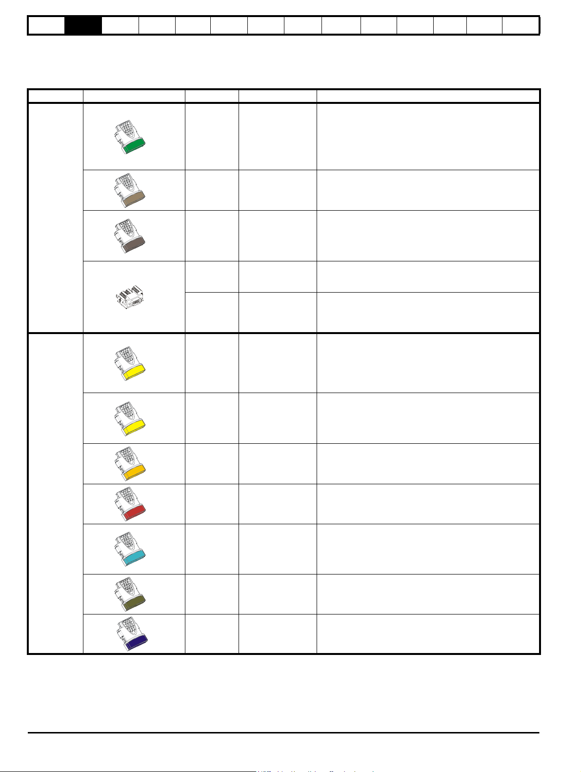
2.2 Model number
The way in which the model numbers for the Mentor MP range are formed is described in Figure 2-2.
Figure 2-2 Model number
Mentor MP User Guide 7
Issue: 3 www.controltechniques.com

Safety
Model
Auxiliary input voltage/
frequency/current
Field output
voltage current
Line input voltage/
frequency/current
Armature output voltage/
current/overload
Rating
Customer and
date code
Approvals
Serial number
IP Rating
Key to approvals
UL approval Worldwide
CE approval Europe
C Tick approval Australia
RoHS compliant Europe
R
Information
Product
information
Mechanical
Installation
Electrical
installation
Getting
started
2.3 Compatible encoders
Table 2-5 Encoders compatible with Mentor MP
Encoder type
Quadrature incremental encoders with or without
marker pulse
Frequency and direction incremental encoders with
or without marker pulse
Forward / reverse incremental encoders with or
without marker pulse
2.4 Nameplate description
Figure 2-3 Typical drive rating label
Basic
parameters
Pr 3.38
(Fb07, 0.77)
setting
Running the
Ab (0)
Fd (1)
Fr (2)
motor
Optimization
SMARTCARD
operation
Onboard
PLC
Advanced
parameters
Technical
data
Diagnostics
UL
information
2.4.1 Output current
The continuous output current ratings given on the rating label are for maximum 40°C (104°F) and 1000m altitude. Derating is required for higher
ambient temperatures >40°C (104°F) and higher altitude. For derating information, refer to section 12.1.12 Altitude on page 150.
2.4.2 Input current
The input current is affected by the supply voltage, frequency and load inductance. The input current given on the rating label is the typical input
current.
8 Mentor MP User Guide
www.controltechniques.com Issue: 3

Safety
SM-Keypad /
MP-Keypad
Automation Fieldbus
Feedback
SMARTCARD*
Keypad
connection
Slot 1
Slot 2
Slot 3
Solutions Modules
Serial port connector
Control terminals
FXMP25 connection
Auxiliary connections
and field
Field fuses
DC
terminals
AC terminals
CT Comms cable
Identification
marker rail
Machine
feedback
terminals
FXMP25
M
STORED CHARGE
10 min
Mode /Reset
FXMP25 Field regulator
Automation
Fieldbus
Feedback
SMARTCARD*
SM-Keypad /
MP-Keypad
Keypad
connection
Slot 1
Slot 2
Slot 3
Solutions Modules
Serial port connector
Control terminals
FXMP25 connection
Auxiliary connections
and field
Field fuses
AC terminals
CT Comms cable
Identification
marker rail
Machine
feedback
terminals
DC
terminals
Paralleling port
FXMP25
M
STORED CHARGE
10 min
Mode /Reset
Internal
fans
FXMP25 Field regulator
Information
Product
information
Mechanical
Installation
Electrical
installation
Getting
started
2.5 Drive features and options
Figure 2-4 Drive features and options on size 1
Basic
parameters
Running the
motor
Optimization
SMARTCARD
operation
Onboard
PLC
Advanced
parameters
Technical
data
Diagnostics
UL
information
Figure 2-5 Drive features and options for size 2
* A SMARTCARD is provided as standard. For further information, refer to Chapter 9 SMARTCARD operation on page 81.
Mentor MP User Guide 9
Issue: 3 www.controltechniques.com
Safety
Inputs Outputs
• Incremental encoders • Quadrature
• SinCos encoders • Frequency and direction
• SSI encoders • SSI simulated outputs
• EnDat encoders
• Digital inputs x 3
• Analog output (voltage) x 1
• Digital I/O x 3 • Relay x 2
• Analog inputs (voltage) x 2
Information
Product
information
Mechanical
Installation
Electrical
installation
Getting
started
Basic
parameters
Running the
motor
Optimization
SMARTCARD
operation
Onboard
PLC
Advanced
parameters
Technical
data
Diagnostics
UL
information
2.5.1 Options available for Mentor MP
All Solutions Modules are color-coded in order to make identification easy. The following table shows the color-code key and gives further details on
their function.
Table 2-6 Solutions Module identification
Type Solutions Module Color Name Further Details
Universal Feedback interface
Feedback interface for the following devices:
Light Green
Brown SM-Encoder Plus
Feedback
Dark Brown
N/A
N/A
Yellow SM-I/O Plus
SM-Universal
Encoder Plus
SM-Encoder Output
Plus
15-way D-type
converter
Single ended
encoder interface
(15V or 24V)
Incremental encoder interface
Feedback interface for incremental encoders without
commutation signals.
No simulated encoder outputs available
Incremental encoder interface
Feedback interface for incremental encoders without
commutation signals.
Simulated encoder output for quadrature, frequency and
direction signals
Drive encoder input converter
Provides screw terminal interface for encoder wiring and spade
terminal for shield
Single ended encoder interface
Provides an interface for single ended ABZ encoder signals,
such as those from hall effect sensors. 15V and 24V versions
are available.
Extended I/O interface
Increases the I/O capability by adding the following to the
existing I/O in the drive:
Automation
(I/O
Expansion)
Yellow SM-I/O 32
Dark Yellow SM-I/O Lite
Dark Red SM-I/O Timer
Turquoise SM-I/O PELV
Olive SM-I/O 120V
Cobalt Blue
SM-I/O 24V
Protected
Extended I/O interface
Increase the I/O capability by adding the following to the
existing I/O in the drive:
• High speed digital I/O x 32
• +24V output
Additional I/O
1 x Analog input (± 10V bi-polar or current modes)
1 x Analog output (0 to 10V or current modes)
3 x Digital input and 1 x Relay
Additional I/O with real time clock
As per SM-I/O Lite but with the addition of a Real Time Clock
for scheduling drive running
Isolated I/O to NAMUR NE37 specifications
For chemical industry applications
1 x Analog input (current modes)
2 x Analog outputs (current modes)
4 x Digital input / outputs, 1 x Digital input, 2 x Relay outputs
Additional I/O conforming to IEC 61131-2 120Vac
6 digital inputs and 2 relay outputs rated for 120Vac operation
Additional I/O with overvoltage protection up to 48V
2 x Analog outputs (current modes)
4 x Digital input / outputs, 3 x Digital inputs, 2 x Relay outputs
10 Mentor MP User Guide
www.controltechniques.com Issue: 3

Safety
FXMP25
M
STORED CHARGE
10 min
Mode /Reset
Information
Product
information
Mechanical
Installation
Electrical
installation
Getting
started
Basic
parameters
Running the
motor
Optimization
SMARTCARD
operation
Onboard
PLC
Advanced
parameters
Table 2-6 Solutions Module identification
Type Solutions Module Color Name Further Details
Applications Processor (with CTNet)
Moss Green
SM-Applications
Plus
nd
2
processor for running pre-defined and /or customer created
application software with CTNet support. Enhanced
performance over SM-Applications
Applications Processor
Automation
(Applications)
White
SM-Applications Lite
V2
nd
2
processor for running pre-defined and /or customer created
application software. Enhanced performance over SMApplications Lite
Applications Processor
Green brown SM-Register
nd
2
processor for running position capture functionality with
CTNet support.
Technical
data
Diagnostics
UL
information
Fieldbus
Table 2-7 Keypad identification
Keypad Name Further Details
SM-Keypad
Purple
SM-PROFIBUS DP-V1Profibus option
Medium Grey SM-DeviceNet
Dark Grey SM-INTERBUS
Light Grey SM-CANopen
Beige SM-Ethernet
Brown Red SM-EtherCAT
LED keypad option
Keypad with a LED display
PROFIBUS DP adapter for communications with the drive
DeviceNet option
Devicenet adapter for communications with the drive
Interbus option
Interbus adapter for communications with the drive
CANopen option
CANopen adapter for communications with the drive
Ethernet option
10 base-T / 100 base-T; Supports web pages, SMTP mail and
multiple protocols: DHCP IP addressing; Standard RJ45
connection
EtherCAT option
EtherCAT adapter for communications with the drive
MP-Keypad
LCD keypad option
Keypad with an alpha-numeric LCD display with Help function
Table 2-8 Serial comms lead
Serial comms lead Name Further Details
CT Comms cable
CT EIA (RS) -232 (4500-0087)
CT USB (4500-0096)
Table 2-9 External field control
External field controller Name Further Details
FXMP25
Mentor MP User Guide 11
For external control of field windings up to 25A, with field reversal capability. For further
information, please see the FXMP25 User Guide.
Issue: 3 www.controltechniques.com
Safety
CAUTION
Risk of Electric Shock
Power down unit 10minutes
before removing cover
Information
Product
information
Mechanical
Installation
Electrical
installation
Getting
started
Basic
parameters
Running the
motor
Optimization
SMARTCARD
operation
Onboard
PLC
Advanced
parameters
Technical
data
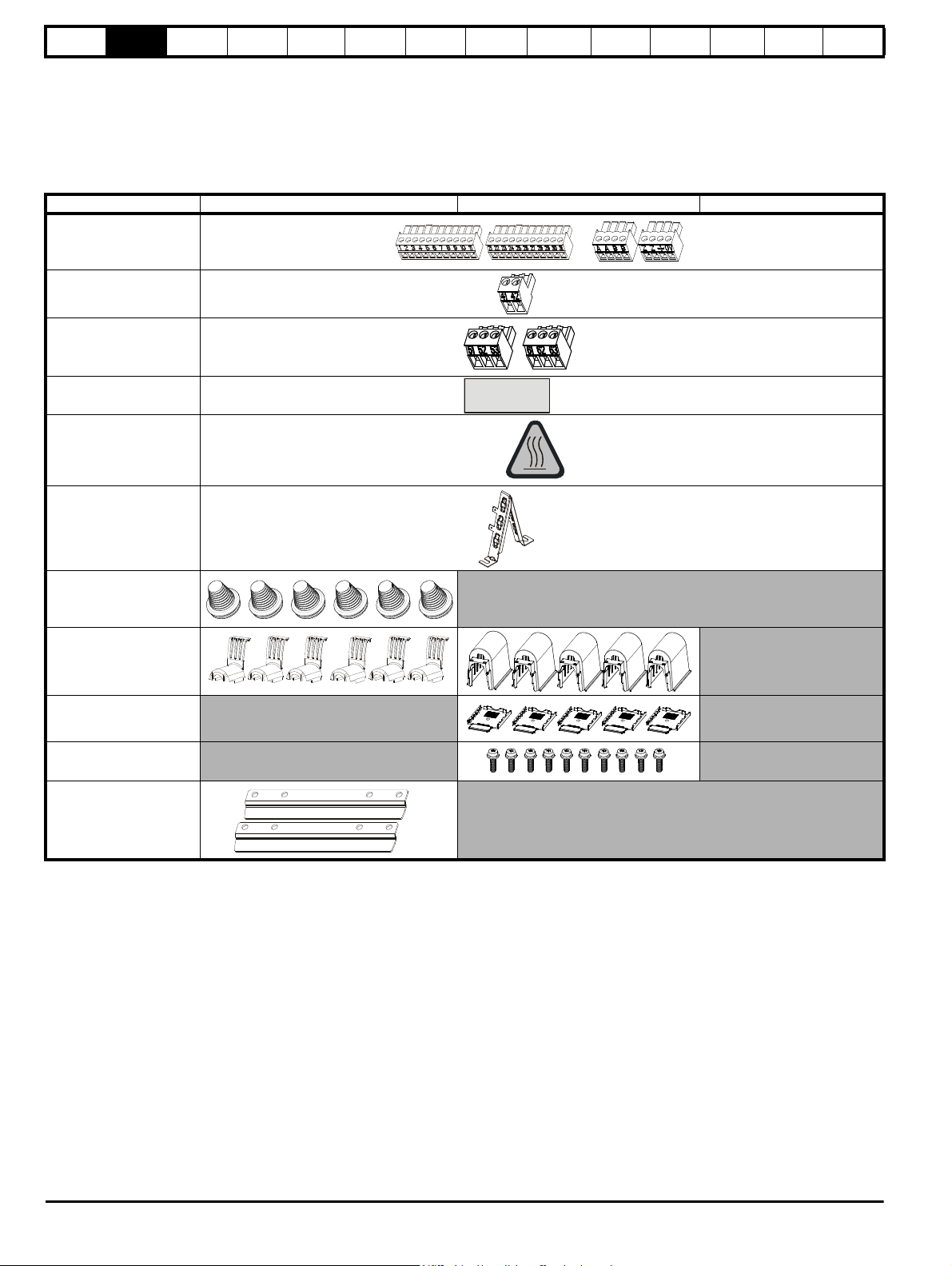
2.6 Items supplied with the drive
The drive is supplied with a printed manual, a SMARTCARD, a safety
information booklet, the Certificate of Quality, an accessory kit box
including the items shown in Table 2-10, and a CD ROM containing all
related product documentation and software tools.
Table 2-10 Parts supplied with the drive
Description Size 1 Size 2A / 2B Size 2C / 2D
Control connectors
Tacho connector
Relay connectors
UL warning label
UL warning label for
heatsink temperature
Diagnostics
UL
information
Grounding bracket
Terminal cover grommets
Terminal shrouds
Terminal shroud base
covers
M4 Screws
Mounting feet bracket
12 Mentor MP User Guide
www.controltechniques.com Issue: 3
Safety
WARNING
WARNING
WARNING
WARNING
WARNING
WARNING
Information
Product
information
Mechanical
Installation
Electrical
installation
Getting
started
Basic
parameters
Running the
motor
Optimization
SMARTCARD
operation
Onboard
PLC
Advanced
parameters
Technical
data
Diagnostics
UL
information
3 Mechanical Installation
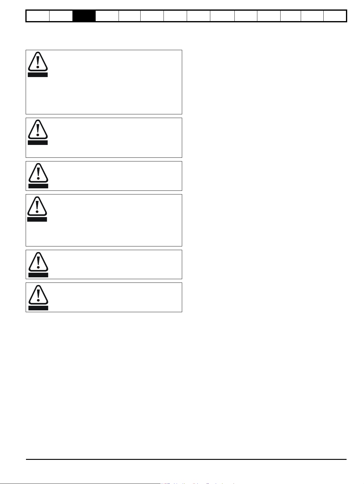
3.1 Safety
Follow the instructions
The mechanical and electrical installation instructions must
be adhered to. Any questions or doubt should be referred to
the supplier of the equipment. It is the responsibility of the
owner or user to ensure that the installation of the drive and
any external option unit, and the way in which they are
operated and maintained, comply with the requirements of
the Health and Safety at Work Act in the United Kingdom or
applicable legislation and regulations and codes of practice
in the country in which the equipment is used.
Competence of the installer
The drive must be installed by professional assemblers who
are familiar with the requirements for safety and EMC. The
assembler is responsible for ensuring that the end product or
system complies with all the relevant laws in the country
where it is to be used.
If the drive has been used at high load levels for a period of
time, the heatsink can reach temperatures in excess of 70°C
(158°F). Human contact with the heatsink should be
prevented.
Enclosure
The drive is intended to be mounted in an enclosure which
prevents access except by trained and authorized
personnel, and which prevents the ingress of contamination.
It is designed for use in an environment classified as
pollution degree 2 in accordance with IEC 60664-1. This
means that only dry, non-conducting contamination is
acceptable.
3.2.3 Cooling
The heat produced by the drive must be removed without its specified
operating temperature being exceeded. Note that a sealed enclosure
gives much reduced cooling compared with a ventilated one, and may
need to be larger and/or use internal air circulating fans.
For further information, refer to section 3.6.2 Enclosure sizing on
page 26.
3.2.4 Electrical safety
The installation must be safe under normal and fault conditions.
Electrical installation instructions are given in Chapter 4 Electrical
installation on page 32.
3.2.5 Electromagnetic compatibility
If it is necessary to meet strict emission limits, or if it is known that
electromagnetically sensitive equipment is located nearby, then full
precautions must be observed. The use of an external EMC filter may be
required at the drive inputs, which must be located very close to the
drives.
Space must be made available for the filters and allowance made for
carefully segregated wiring. Both levels of precautions are covered in
Table 12-42 Drive power stage terminals on size 2 drives on page 164.
3.2.6 Hazardous areas
The drive must not be located in a classified hazardous area unless it is
installed in an approved enclosure and the installation is certified.
The drive enclosure is not classified as a fire enclosure. A
separate fire enclosure must be provided.
Many of the drives in this product range weigh in excess of
15kg (33lb). Use appropriate safeguards when lifting these
models.
See section 3.4 Mounting method on page 17.
3.2 Planning the installation
The following considerations must be made when planning the
installation:
3.2.1 Access
Access must be restricted to personnel only. Safety regulations which
apply at the place of use must be complied with.
3.2.2 Environmental protection
The drive must be protected from:
• moisture, including dripping water or spraying water and
condensation. An anti-condensation heater may be required, which
must be switched off when the drive is running
• contamination with electrically conductive material
• contamination with any form of dust which may restrict the fan, or
impair airflow over various components
• temperature beyond the specified operating and storage ranges
• corrosive gasses
Mentor MP User Guide 13
Issue: 3 www.controltechniques.com
Safety
WARNING
WARNING
Pozi Pz2
1
2
All sizes
Information
Product
information
Mechanical
Installation
Electrical
installation
Getting
started
Basic
parameters
Running the
3.3 Terminal cover removal
Isolation device
The AC supply must be disconnected from the drive using an
approved isolation device before any cover is removed from
the drive or before any servicing work is performed.
Stored charge
The drive contains capacitors that remain charged to a
potentially lethal voltage after the AC supply has been
disconnected. If the drive has been energized, the AC
supply must be isolated at least ten minutes before work
may continue.
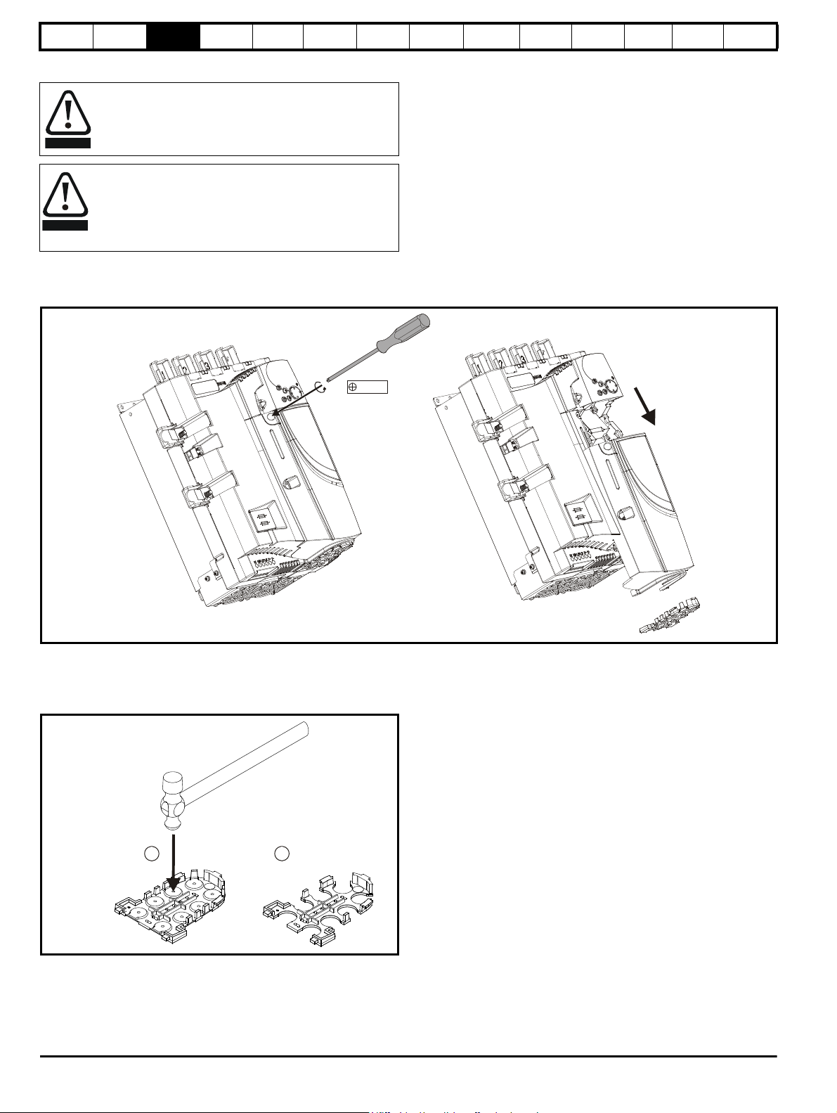
3.3.1 Removing the terminal covers
The drive is installed with one control terminal cover.
Figure 3-1 Removing the control terminal cover (size 1 shown)
motor
Optimization
SMARTCARD
operation
Onboard
PLC
Advanced
parameters
Technical
data
Diagnostics
UL
information
To remove the terminal cover, undo the screw and slide the terminal cover downwards.
When replacing the terminal covers the screw should be tightened with a maximum torque of 1 Nm (0.7 Ib ft).
3.3.2 Removing the finger-guard and break-outs
Figure 3-2 Removing the finger-guard break-outs
Place finger-guard on a flat solid surface and hit relevant break-outs with
hammer as shown (1). Continue until all required break-outs are removed
(2). Remove any flash / sharp edges once the break-outs are removed.
14 Mentor MP User Guide
www.controltechniques.com Issue: 3

Safety
CAUTION
A
B
Solutions Module
in slot 1
Solutions Module
in slot 2
Solutions Module
in slot 3
A
NOTE
Information
Product
information
Mechanical
Installation
Electrical
installation
Getting
started
Basic
parameters
Running the
motor
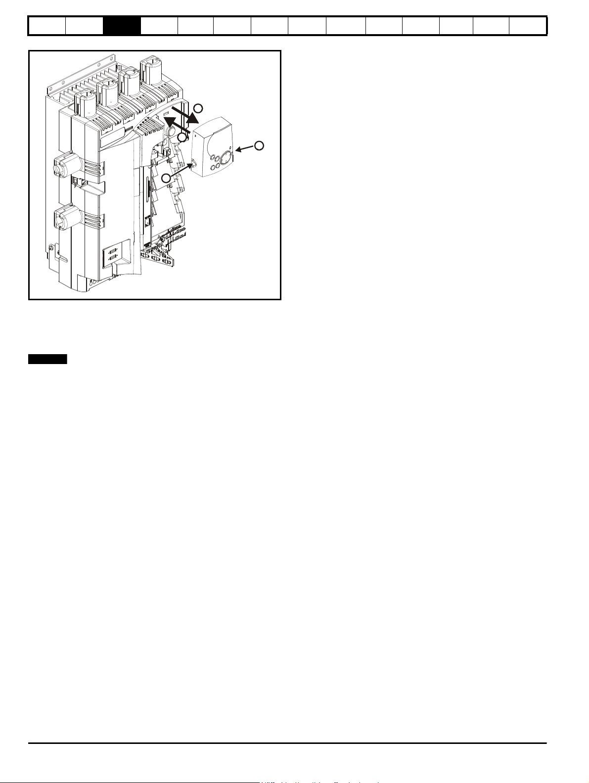
3.3.3 Installation and removal of a Solutions Module
Please power down the drive before removing / installing the
Solutions Module. Failure to do so may cause damage to
product
Figure 3-3 Installation and removal of the Solutions Module
Optimization
SMARTCARD
operation
Onboard
PLC
Advanced
parameters
Technical
data
Diagnostics
UL
information
1. To install the Solutions Module, press down in the direction shown
above until it clicks into place.
2. To remove the Solutions Module, press inwards at the points shown
(A) and pull in the direction shown (B).
3. The drive has the facility for all three Solutions Module slots to be
used at the same time, as illustrated.
It is recommended that the Solutions Module slots are used in the
following order: slot 3, slot 2 and slot 1.
Mentor MP User Guide 15
Issue: 3 www.controltechniques.com
Safety
B
B
C
A
NOTE
Information
Product
information
Mechanical
Installation
Electrical
installation
Getting
started
Basic
parameters
Running the
motor
Figure 3-4 Removal and installation of a keypad
To fit, align the MP-Keypad and press gently in the direction shown until
it clicks into position (A).
To remove, while pressing the tabs inwards (B), gently lift the MPKeypad in the direction indicated (C).
Optimization
SMARTCARD
operation
Onboard
PLC
Advanced
parameters
Technical
data
Diagnostics
UL
information
The keypad can be installed / removed while the drive is powered up and
running a motor, providing that the drive is not operating in keypad
mode.
16 Mentor MP User Guide
www.controltechniques.com Issue: 3
Safety
WARNING
WARNING
293mm (11.54in)
250mm (9.84in)
444mm
(17.48in)
222mm
(8.74in)
95mm
(3.74in)
222mm (8.74in)
170mm (6.69in)
6.5mm (0.26in)
250mm (9.84in)
40mm
(1.58in)
22mm
(0.87in)
380mm
(14.96in)
4 holes to
suit M6
1
1
1
1
MA1
MA2
NOTE
NOTE
Information
Product
information
Mechanical
Installation
Electrical
installation
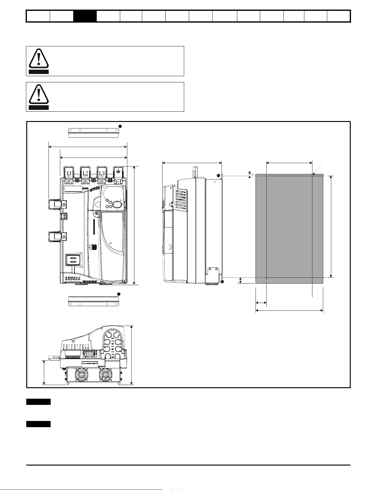
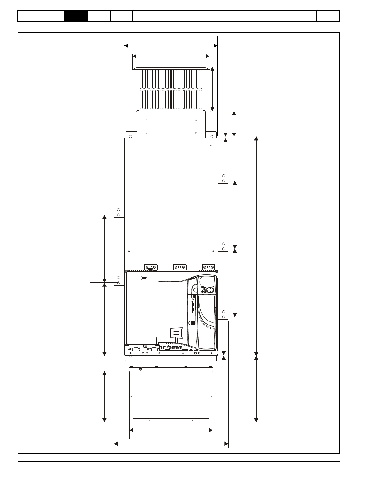
3.4 Mounting method
The Mentor MP can only be surface mounted.
If the drive has been used at high load levels for a period of
time, the heatsink can reach temperatures in excess of 70°C
(158°F). Human contact with the heatsink should be
prevented.
Many of the drives in this product range weigh in excess of
15kg (33lb). Use appropriate safeguards when lifting these
models.
Figure 3-5 Overall size 1A dimensions
Getting
started
Basic
parameters
Running the
motor
Optimization
SMARTCARD
operation
Onboard
PLC
Advanced
parameters
Technical
data
Diagnostics
UL
information
1. The two outer holes must be used for mounting the Mentor MP.
With the SMARTCARD installed to the drive, the depth measurement
increases by 7.6mm (0.30 in).
Fans are only installed to the MP75A4(R) and MP75A5(R).
Mentor MP User Guide 17
Issue: 3 www.controltechniques.com

Safety
293mm (11.54in)
250mm (9.84in)
444mm
(17.48in)
251mm
(9.88in)
124mm
(4.88in)
170mm (6.69in)
6.5mm (0.26in)
250mm (9.84in)
40mm
(1.58in)
22mm
(0.87in)
380mm
(14.96in)
4 holes to
suit M6
1
1
1
1
1
MA1
MA2
NOTE
Information
Product
information
Mechanical
Installation
Electrical
installation
Figure 3-6 Overall size 1B dimensions
Getting
started
Basic
parameters
Running the
motor
Optimization
SMARTCARD
operation
Onboard
PLC
Advanced
parameters
Technical
data
Diagnostics
UL
information
1. The two outer holes must be used for mounting the Mentor MP.
With the SMARTCARD installed to the drive, the depth measurement increases by 7.6mm (0.30 in).
18 Mentor MP User Guide
www.controltechniques.com Issue: 3
Safety
1
1
2
MA1
MA2
453mm (17.84in)
495mm (19.49in)
640mm
(25.20in)
85mm
(3.35in)
301mm (11.85in)
472mm (18.58)
68mm
(2.68in)
126mm
(4.96in)
11.5mm (0.45in)
495mm (19.49in)
80mm
(3.15in)
80mm
(3.15in)
65mm
(2.56in)
8 holes to
suit M8
302mm
(11.89in)
93mm
(3.66in)
NOTE
Information
Product
information
Mechanical
Installation
Electrical
installation
Getting
started
Basic
parameters
Running the
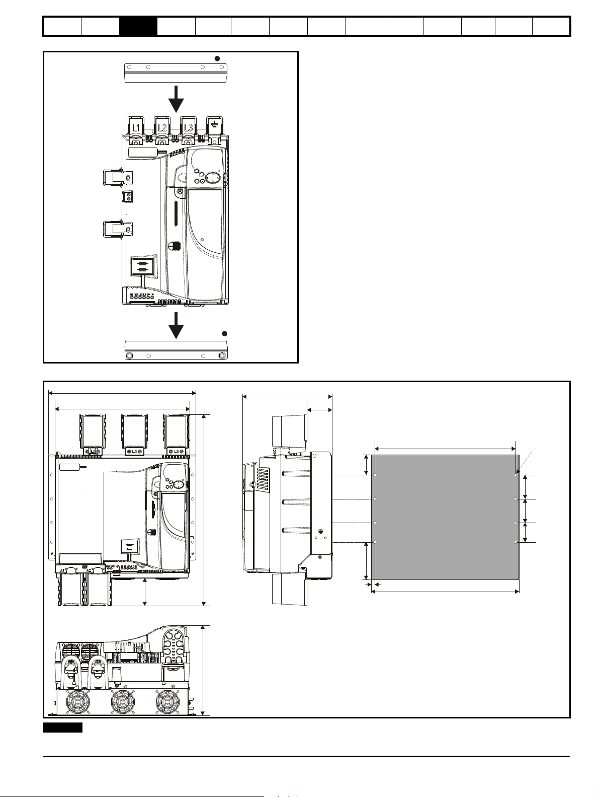
Figure 3-7 Installing the mounting feet bracket on size 1 drives
motor
Optimization
SMARTCARD
operation
Onboard
PLC
Advanced
parameters
Technical
data
Diagnostics
The bottom mounting bracket (1) should be installed to the back plate first
with the screws fully tightened. The drive should then be lowered onto the
bracket and slotted in. The top mounting bracket (2) should then be slotted
into the drive and the top holes marked for mounting (380mm [14.96 in]
from the centre of the holes on the bottom mounting bracket). Once the
holes have been drilled, fix the top mounting bracket accordingly and
tighten the screws.
It is not necessary to tighten the bottom mounting brackets with the drive in
place. The brackets are designed to clamp the drive heatsink against the
back plate.
UL
information
Figure 3-8 Overall size 2A / 2B dimensions
With the SMARTCARD installed to the drive, the depth measurement increases by 7.6mm (0.30 in).
Mentor MP User Guide 19
Issue: 3 www.controltechniques.com

Safety
6mm (0.24in)
175mm (6.9in)
5mm
(0.2in)
175mm (6.9in)
405mm (15.94)
248mm (9.76in)
202mm (7.95in)
321mm (12.64in)
605mm (23.82in)
124mm
(4.89in)
175mm (6.9in)
555mm (21.85in)
452mm (17.8in)
2
0
2
mm (7.95in)
390mm (15.35in)
Information
Product
information
Mechanical
Installation
Electrical
installation
Getting
started
Basic
parameters
Figure 3-9 Size 2C front view and mounting dimensions
Running the
motor
Optimization
SMARTCARD
operation
Onboard
PLC
Advanced
parameters
Technical
data
Diagnostics
UL
information
20 Mentor MP User Guide
www.controltechniques.com Issue: 3

Safety
394mm (15.51in)
605mm
(23.82in)
53mm
(2.09in)
288mm
(11.34in)
450mm (17.72in)
1050mm (41.34in)
306mm (12.05in)
611mm (24.05in)
35mm
(1.38in)
38mm (1.5in)
59mm
(2.32in)
270mm
(10.63in)
4 holes
to suit M10
260mm
(10.24in)
180mm (7.09in)
180mm (7.09in)
90mm
(3.54in)
90mm
(3.54in)
68.5mm
(2.70in)
50mm
(1.97in)
190mm
(7.48in)
240mm
(9.45in)
333mm (13.11in)
83.5
(3.29in)
210mm
(8.27in)
Rear
Front
8 holes
∅
7mm
1
NOTE
NOTE
Information
Product
information
Mechanical
Installation
Electrical
installation
Getting
started
parameters
Figure 3-10 Size 2C back-plate and mounting detail
Basic
Running the
motor
Optimization
SMARTCARD
operation
Onboard
PLC
Advanced
parameters
Technical
data
Diagnostics
UL
information
1. M10 eye-bolts can be inserted in the location shown for lifting the drive. These are not supplied with the drive.
With the SMARTCARD installed in the drive, the depth measurement increases by 7.6mm (0.30 in).
Mentor MP User Guide 21
Issue: 3 www.controltechniques.com
Safety
124m
m
(4.88
in)
6mm
(0.24in)
1065mm (41.93in)
356mm (14.02in)
248mm (9.76in)
405mm (15.94in)
4mm
(0.16in)
321mm (12.64in)
330mm (13.0in)
555mm (21.85in)
330mm (13.0in)
330mm (13.0in)
452mm (17.8in)
202mm (7.95in)
390mm (15.35in)
Information
Product
information
Mechanical
Installation
Electrical
installation
Getting
started
Basic
parameters
Figure 3-11 Size 2D front view and mounting dimensions
Running the
motor
Optimization
SMARTCARD
operation
Onboard
PLC
Advanced
parameters
Technical
data
Diagnostics
UL
information
22 Mentor MP User Guide
www.controltechniques.com Issue: 3

Safety
53mm
(2.09in)
1065mm (41.93in)
288mm (11.34in)
450mm (17.72in)
394mm (15.51in)
1510mm (59.45in)
611mm (24.06in)
306mm (12.05in)
4 holes
to suit M10
35mm
(1.38in)
260mm
(10.24in)
180mm (7.09in)
180mm (7.09in)
90mm
(3.54in)
90mm
(3.54in)
68.5mm
(2.70in)
50mm
(1.97in)
190mm
(7.48in)
240mm
(9.45in)
333mm (13.11in)
8 holes
∅
7mm
83.5mm
(3.29in)
210mm
(8.27in)
1
NOTE
NOTE
Information
Product
information
Mechanical
Installation
Electrical
installation
Getting
started
parameters
Figure 3-12 Size 2D back-plate and mounting detail
Basic
Running the
motor
Optimization
SMARTCARD
operation
Onboard
PLC
Advanced
parameters
Technical
data
Diagnostics
UL
information
1. M10 eye-bolts can be inserted in the location shown for lifting the drive. These are not supplied with the drive.
With the SMARTCARD installed to the drive, the depth measurement increases by 7.6mm (0.30 in).
Mentor MP User Guide 23
Issue: 3 www.controltechniques.com
Safety
NOTE
1
2
3
Information
Product
information
Mechanical
Installation
Electrical
installation
Getting
started
Basic
parameters
Running the
motor
Optimization
SMARTCARD
operation
Onboard
PLC
Advanced
parameters
Technical
data
Diagnostics
UL
information
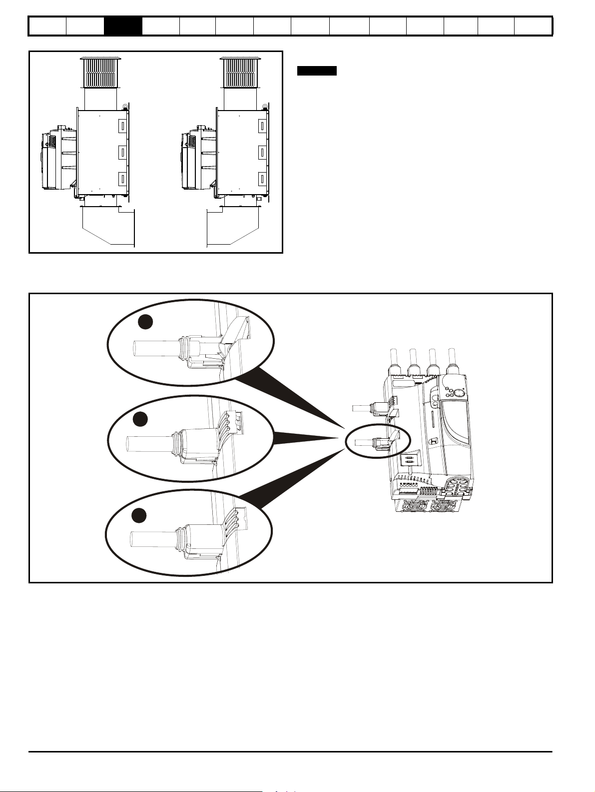
Figure 3-13 Mounting methods of size 2C / 2D air duct The Mentor MP size 2C and 2D air duct can be turned 180° to suit the
customers infrastructure.
There is no seal provided with this product for sealing off the gap around
the air duct when mounted.
3.5 Installing and removing the terminal shrouds
Figure 3-14 Installing the terminal shrouds on size 1 drives
1. Thread the AC supply and DC output connectors through the grommets provided and connect them to the drive.
2. Place the terminal shroud over the top of the connectors and click into place (3).
24 Mentor MP User Guide
www.controltechniques.com Issue: 3

Safety
1
2
L1 L2
L3
A1 A2
1
2
3
NOTE
Information
Product
information
Mechanical
Installation
Electrical
installation
Getting
started
Basic
parameters
Running the
motor
Figure 3-15 Removing the terminal shrouds on size 1 drives
1. Insert the screwdriver as shown.
2. Lever in the direction shown to unclip the terminal shroud and remove.
Figure 3-16 Installing the terminal shrouds on size 2 drives
Optimization
SMARTCARD
operation
Onboard
PLC
Advanced
parameters
Technical
data
Diagnostics
UL
information
1. Assemble the cable to the busbar.
2. Place the terminal shroud base cover underneath the cable in the orientation shown.
3. Place the terminal shroud over the cable in the orientation shown, slide the terminal shroud on to the base cover in the direction shown until it
clicks in to place.
4. For all power connections slide in the terminal shroud sub-assembly in the direction as shown.
5. Insert the 2 x M4 x 16 screws using a pozi drive screwdriver.
To remove the terminal shrouds, please reverse the process above.
Mentor MP User Guide 25
Issue: 3 www.controltechniques.com

Safety
Enclosure
AC supply contactor,
line chokes and fuses
External
controller
Ensure minimum clearances
are maintained for the drive.
Forced or convection air-flow
must not be restricted by any
object or cabling
Auxillary
supply
Signal cables
Plan for all signal cables
to be routed at least
300mm (12in) from the
drive and any power cable
Armature
connection
cable
Field
connection cable
≥
100mm(4in)
≥
100mm
(4in)
A
A
MA1
MA2
Note
For EMC compliance:
1) Power cabling must be at
least 100mm (4in) from the
drive in all directions
2) Ensure direct metal contact
at drive and filter mounting
points (any paint must be
removed)
100mm for Size 1 drives
200mm for Size 2A/2B drives
A
Note
For Size 2C/2D drives
leave a clearance of 100mm
around the drive.
A
e
P
kT
intText
–()
----------------------------------------
=
Information
Product
information
Mechanical
Installation
Electrical
installation
Getting
started
Basic
parameters
Running the
motor
Optimization
SMARTCARD
operation
Onboard
PLC
Advanced
parameters
Technical
data
Diagnostics
UL
information
3.6 Enclosure
3.6.1 Enclosure layout
Please observe the clearances in the diagram below taking into account any appropriate notes for other devices / auxiliary equipment when planning
the installation.
Figure 3-17 Enclosure layout
3.6.2 Enclosure sizing
Refer to section 12.1.2 Typical short-term overload limits on page 145
for drive losses.
Add the dissipation figures for each drive that is to be installed in the
enclosure.
Add the power dissipation figures for each EMC filter that is to be
installed in the enclosure.
Calculate the total heat dissipation (in Watts) of any other equipment to
be installed in the enclosure.
Add the figures of all of the above to get a total heat dissipation figure (in
Watts) for the equipment in the enclosure.
Calculating the size of a sealed enclosure
The enclosure transfers internally generated heat into the surrounding
air by natural convection. The larger the surface area of the enclosure
walls, the better is the dissipation capability. Only the surfaces of the
enclosure that are not in contact with a wall or floor can dissipate heat.
Calculate the minimum required unobstructed surface area A
enclosure from:
for the
e
Where:
Unobstructed surface area in m2 (1 m2 = 10.9 ft2)
A
e
T
ext
Maximum expected temperature in oC outside the
enclosure
int
P Power in Watts dissipated by all heat sources in the
k Heat transmission coefficient of the enclosure material
Example
To calculate the size of an enclosure for the following:
enclosure
enclosure
2/o
in W/m
C
Maximum permissible temperature in oC inside the
T
• Two MP25A4 models operating under full load conditions
• Maximum ambient temperature inside the enclosure: 40°C
• Maximum ambient temperature outside the enclosure: 30°C
Dissipation of each drive: 125W
Dissipation from other heat generating equipment in the enclosure. 11W
(max).
Total dissipation: 2 x (125 + 11) = 272W
26 Mentor MP User Guide
www.controltechniques.com Issue: 3
Safety
W
H
D
A
e
272W
5.5 40 30–()
---------------------------------
=
W
A
e
2HD–
HD+
--------------------------
=
W
4.945 2 2× 0.6×()–
20.6+
-----------------------------------------------------
=
V
3kP
T
intText
–
---------------------------
=
P
o
P
l
-------
V
31.3× 549×
40 30–
----------------------------------
=
WARNING
Information
Product
information
Mechanical
Installation
Electrical
installation
Getting
started
Basic
parameters
Running the
motor
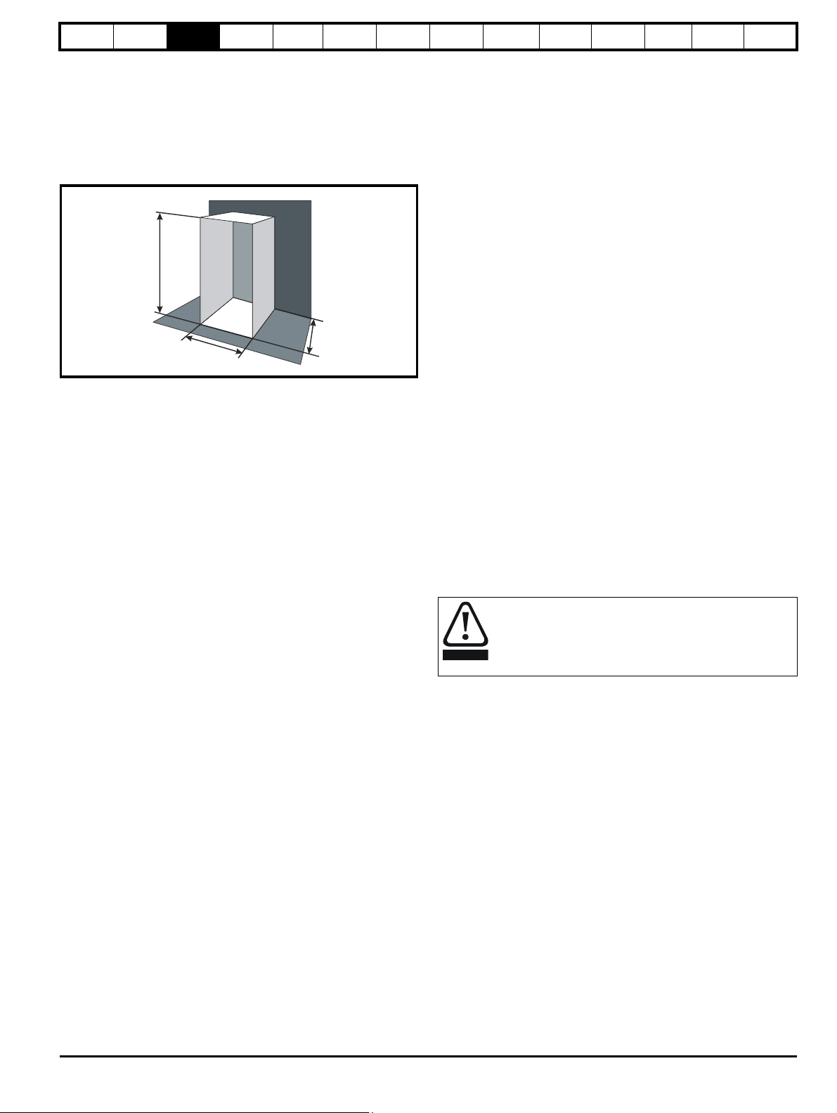
The enclosure is to be made from painted 2mm (0.079in) sheet steel
having a heat transmission coefficient of 5.5 W/m
2/o
C. Only the top,
front, and two sides of the enclosure are free to dissipate heat.
The value of 5.5 W/m
2
/ºC can generally be used with a sheet steel
enclosure (exact values can be obtained by the supplier of the material).
If in any doubt, allow for a greater margin in the temperature rise.
Figure 3-18 Enclosure having front, sides and top panels free to
dissipate heat
Insert the following values:
T
40°C
int
30°C
T
ext
k 5.5
P 272W
The minimum required heat conducting area is then:
2
= 4.945 m
(53.90 ft2) (1 m2 = 10.9 ft2)
Estimate two of the enclosure dimensions - the height (H) and depth (D),
for instance. Calculate the width (W) from:
Optimization
SMARTCARD
operation
Onboard
PLC
Advanced
parameters
Technical
data
Diagnostics
information
Where:
P
is the air pressure at sea level
0
is the air pressure at the installation
P
I
Typically use a factor of 1.2 to 1.3, to allow also for pressure-drops in
dirty air-filters.
Example
To calculate the size of an enclosure for the following:
• Three MP45A4 models operating under full load conditions
• Maximum ambient temperature inside the enclosure: 40°C
• Maximum ambient temperature outside the enclosure: 30°C
Dissipation of each drive: 168W
Dissipation from other heat generating equipment. 15 W
Total dissipation: 3 x (168 + 15) = 549W
Insert the following values:
40°C
T
int
T
30°C
ext
k 1.3
P 549W
Then:
= 214.1 m
3
/hr (126.3 ft3 /min) (1 m3/ hr = 0.59 ft3/min)
3.7 Heatsink fan operation
Mentor MP drive rated 75A and above are ventilated by internally
supplied fans.
Ensure the minimum clearances around the drive are maintained to
allow the air to flow freely.
The drive controls the fan operation based on the temperature of the
heatsink and the drives thermal model system.
UL
Inserting H = 2m and D = 0.6m, obtain the minimum width:
=0.979 m (38.5 in)
If the enclosure is too large for the space available, it can be made
smaller only by attending to one or all of the following:
• Reducing the ambient temperature outside the enclosure, and/or
applying forced-air cooling to the outside of the enclosure
• Reducing the number of drives in the enclosure
• Removing other heat-generating equipment
Calculating the air-flow in a ventilated enclosure
The dimensions of the enclosure are required only for accommodating
the equipment. The equipment is cooled by the forced air flow.
Calculate the minimum required volume of ventilating air from:
Where:
V Air-flow in m
T
Maximum expected temperature in °C outside the
ext
enclosure
T
Maximum permissible temperature in °C inside the
int
enclosure
P Power in Watts dissipated by all heat sources in the
enclosure
3
per hour (1 m3/hr = 0.59 ft3/min)
3.8 IP rating (Ingress Protection)
IP rating
It is the installer’s responsibility to ensure that any enclosure
which allows access to drives from frame sizes 2A to 2D
while the product is energized, provides protection against
contact and ingress to the requirements of IP20.
An explanation of IP rating is provided in section 12.1.13 IP rating on
page 150.
Mentor MP User Guide 27
Issue: 3 www.controltechniques.com
k Ratio of
Safety
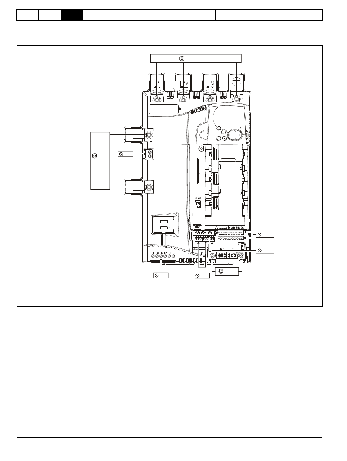
M8 nut / 13 mm AF
AC input
M8 nut
13mm AF
DC output
T25 Torx
Ground
connections
Tac h o
connections
3.5 mm
Relay
connections
3.5mm
5mm
Auxiliary
connections
Control and
encoder
connections
2.5 mm
5mm
Machine
feedback
terminals
MA1
MA2
Information
Product
information
Mechanical
Installation
Electrical
installation
Getting
started
Basic
parameters
Running the
motor
Optimization
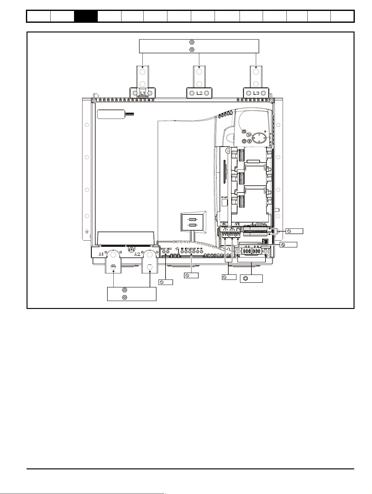
3.9 Electrical terminals
3.9.1 Location of the power and ground terminals
Figure 3-19 Location of the power and ground terminals on size 1 drives
SMARTCARD
operation
Onboard
PLC
Advanced
parameters
Technical
data
Diagnostics
UL
information
28 Mentor MP User Guide
www.controltechniques.com Issue: 3
Safety
5mm
Machine
feedback
terminals
Tac h o
connections
5mm
Auxiliary
connections
Control and
encoder
connections
2.5 mm
Relay
connections
3.5mm
3.5 mm
T25 Torx
Ground
connections
M12 nut 19
mm AF
DC output
Size 2A:
Size 2B:
M10 nut 17
mm AF
AC input
M12 nut 19mm AF
Size 2A:
Size 2B:
M10 nut 17mm AF
Information
Product
information
Mechanical
Installation
Electrical
installation
Getting
started
Basic
parameters
Running the
motor
Optimization
SMARTCARD
Figure 3-20 Location of the power and ground terminals on size 2A and 2B drives
operation
Onboard
PLC
Advanced
parameters
Technical
data
Diagnostics
UL
information
Mentor MP User Guide 29
Issue: 3 www.controltechniques.com

Safety
Control and
encoder
connections
2.5mm
Size 2C / 2D:
M12 nut 19mm AF
5mm
Machine
feedback
terminals
5mm
Auxiliary
connections
Relay
connections
3.5mm
T25 Torx
Ground
connections
Ta ch o
connections
3.5mm
Size 2C / 2D:
M12 nut 19mm AF
AC Input
DC Output
WARNING
Information
Product
information
Mechanical
Installation
Electrical
installation
Getting
started
Basic
parameters
Running the
motor
Optimization
SMARTCARD
Figure 3-21 Location of the power and ground terminals on size 2C and 2D drives
operation
Onboard
PLC
Advanced
parameters
Technical
data
Diagnostics
UL
information
3.9.2 Terminal sizes and torque settings
To avoid a fire hazard and maintain validity of the UL listing,
adhere to the specified tightening torques for the power and
ground terminals. Refer to the following tables.
Table 3-4 Drive power stage terminals on size 2 drives
Model Connection type Torque setting
Size 2A M10 stud 15 Nm (11.06 lb ft)
Size 2B
M12 stud 30 Nm (22.12 Ib ft)Size 2C
3.9.3 Torque settings
Size 2D
Table 3-1 Drive control, status relay and encoder terminal data
Model Connection type Torque setting
All Plug-in terminal block 0.5 Nm 0.4 lb ft
Table 3-2 Drive auxiliary and machine armature terminal data
Model Connection type Torque setting
All Terminal block 0.5 Nm 0.4 lb ft
Table 3-3 Drive power stage terminals on size 1 drives
Model Connection type Torque setting
All M8 stud 10 Nm 7.4 lb ft
30 Mentor MP User Guide
www.controltechniques.com Issue: 3
Loading...