


Operator’s Manual |
ASCO 336 / 337 |
|
Operator’s Manual |
300 Series Power Control System |
|
336 /337 Generator Paralleling System |
||
|
!DANGER
DANGER is used in this manual to warn of a hazard situation which, if not avoided, will result in death or serious injury.
! WARNING
WARNING is used in this manual to warn of a hazardous situation which, if not avoided, could result death or serious injury.
!CAUTION
CAUTION is used in this manual to warn of a hazardous situation which, if not avoided, could result in minor or moderate injury.
Refer to the outline and wiring drawings provided with the 336 / 337 for all installation and connection details and accessories.
Refer to the Controller User’s Guide for status display messages, time delays, pickup and dropout settings, and adjustments.
Rating Label
Each 336/337 PCS contains a rating label to define the loads and fault circuit withstand/closing ratings. Refer to the label on the transfer switch for specific values.
In a non-redundant system, that is, the load current is more than one generator’s full load current and the generators are being paralleled to provide more power to the load, the CTTS current rating must be equal to or greater than the sum of the two generator’s full load amps.
If the application is a redundant system, that is, the load current is equal to or less than the full load amps of one generator and the generators are being paralleled for redundancy, the 336 or 337 rating must be equal to or greater than the full load current of the biggest generator. In addition, the output of the CTTS unit must be protected by an over current device, like a circuit breaker, equal to or less than the CTTS rating label.
! WARNING
Do not exceed the values on the rating label. Exceeding the rating can cause personal injury or serious equipment damage.
Table of Contents |
|
|
page |
INSTALLATION ............................................... |
3 |
FUNCTIONAL TEST.................................... |
5-8 |
OPERATIONAL TESTING ........................ |
9-10 |
FEATURES & OPTIONS......................... |
11-13 |
PROTECTIVE RELAY FUNCTIONS............. |
14 |
TESTING & SERVICE................................... |
15 |
INDEX............................................................ |
16 |
381333-427 A
381333-427 A |
ASCO Power Technologies |
Page 1 |

ASCO 336 / 337 |
Operator’s Manual |
300 Series PCS Family of Products
The ASCO 300 Series Power Control System (PCS) is a family of affordable and feature-rich products for paralleling generators, controlling loads, and connecting generators to the utility power system or grid. Transfer switch based or circuit breaker based power switching options are available to meet the requirements of all applications. The PCS 300 Series control system is an integrated platform that provides sequencing, synchronizing, generator load sharing, protective functions, power management, and many other industryleading features, all while minimizing costs.
Upper
Customer
Terminal
Block
CTs
CTTS
Transfer
Switch
CTs
Lower
Customer
Terminal
Block
336 / 337 PCS
The ASCO 336 / 337 PCS utilize the ASCO Power Technologies industry-leading and time-proven Closed Transition Transfer Switch (CTTS) mechanism to parallel two generators per CTTS unit. The 336 manages the first two generators of any system. The 337 can be added to manage the third and fourth generators of a four generator system. Due to the fault currents available, usually four generators is the limit of a 336/337 PCS system. There are alternatives within the 300 Series for paralleling more generators: contact ASCO Power Technologies for more information.
A 337 may be added later as long as the electrical power infrastructure is compatible. Options must be the same in a 336 and 337 for proper operation.
Controller
Operator
Interface
Terminal
OIT
Typical 336 Series PCS H-design 800-1200 ampere
Page 2 |
ASCO Power Technologies |
381333-427 A |

Operator’s Manual |
ASCO 336 / 337 |
|
|
Automatic Control System
The 336 / 337 is an automatic control system that may start and/or stop generators and operate the transfer switch at any time to maintain power to the load.
! WARNING
Proper precautions must be taken, including tag out / lock out procedures, to ensure personnel safety.
Installation
The system is factory wired and tested. Installation requires mounting, connecting service cables, and connecting generator control and generator circuit breaker control circuits.
NOTICE
System installation and startup by ASCO Power Technologies is recommended.
An experienced licensed electrician must install the system.
Supporting Foundation
The supporting foundation for the enclosure must be level and straight. Refer to the applicable enclosure outline drawing included with the system for all mounting details including door opening space.
If bottom cable entry is used, the foundation must be prepared so that the conduit stubs are located correctly. Refer to the enclosure outline drawing for specified area and location. Provide cable bending space and 1 inch minimum clearance to live metal parts. When a concrete floor is poured, use interlocking conduit spacer caps or a wood or metal template to maintain proper conduit alignment.
Mounting
Refer to the outline and mounting diagram and mount the transfer switch according to details and instructions shown on the diagram. Mount it vertically to a rigid supporting structure. Level all mounting points by using flat washers behind the holes to avoid distortion of the transfer switch.
NOTICE
Protect the transfer switch from construction grit and metal chips to prevent malfunction or shortened life of the transfer switch.
Line Connections
Refer to the wiring diagram provided with the transfer switch. All wiring must be made in accordance with the National Electrical Code and local codes.
!DANGER
De-energize the conductors before making any line or auxiliary circuit connections. Be sure that the Generator 1 and Generator 2 line connections are in proper phase rotation. Place the engine generator starting controls in the OFF position. Make sure engine generators are not in operation.
Testing Power Conductors
Do not connect the power conductors to the transfer switch until they are tested. Installing power cables in conduit, cable troughs, and ceiling-suspended hangers often requires considerable force. The pulling of cables can damage insulation and stretch or break the conductor’s strands. For this reason, after the cables are pulled into position, and before they are connected, they should be tested to verify that they are not defective or have been damaged during installation.
Connecting Power Cables
After the power cables have been tested, connect them to the appropriate terminal lugs (if provided) on the transfer switch as shown on the wiring diagram provided with the transfer switch. Make sure that the lugs are suitable for use with the cables being installed. Be careful when stripping insulation from the cables; avoid nicking or ringing the conductor. Remove surface oxides from cables by cleaning with a wire brush. When aluminum cable is used, apply joint compound to conductors. Tighten cable lugs to the torque specified on rating label.
381333-427 A |
ASCO Power Technologies |
Page 3 |
ASCO 336 / 337 |
Operator’s Manual |
Generator Circuit Breaker Control Circuits
The generator circuit breaker control connections are located on customer terminal block. Connect signal wires to appropriate terminals as specified on the wiring diagram.
Generator circuit breaker
The generator circuit breaker provides the overcurrent (short circuit) protection for the system and functions as a back-up to protect/isolate the system upon a fault during the loss of AC control power. It does not matter if the generator circuit breaker is manually operated close or electrically operated close, but it must have a shunt trip and auxiliary contacts.
The control system has a dry contact (CTBx:19 to CTBx: 20, rated at 8A, 30VDC or 8A, 250VAC, tripping duty) available for shunt tripping the generator circuit breaker. This contact must be connected during installation.
CTBx: x is the generator number.
Gen1 is CTB1, Gen 2 is CTB2.
There is an option to have wire break monitoring of this shunt trip coil. This requires (1) the shunt trip coil to be 24Vdc, (2) supplied from the same source as the control system (normally the generator batteries), and (3) not connected to any other tripping circuit devices. This wire break system functions by passing a small amount of current thru the breaker trip coil; if this current gets too low, a wire break is assumed. If any other devices are connected, for example indicating lights or other trip devices, the wire break function may not work. The maximum resistance of the trip coil circuit that this function will work is 100 ohms. That is, if the circuit resistance exceeds 100 ohms, this function will alarm a wire break. Default from the factory is this feature is not enabled; ASI may enable it during startup.
If the generator circuit breaker is open the control system needs to know that this gen-set is not available. This requires a normally open dry contact (52/a: closed when the circuit breaker main contacts are closed) to be wired to the control system, CTBx:9 to CTBx:10. There should be no other connections to this circuit. This is a contact input, wetted by internal 24VDC (interrogation voltage) from the controller power. If the generator circuit breaker is open, this generator is not available and the Power Management option will not include this generator in the gen shed/gen add program.
If the generator circuit breaker opens for any reason, the CTTS will open when AC control power is available. The control system will alarm and not be available until the generator circuit breaker is closed again and the alarm is reset. If this is the only generator running and the circuit breaker trips, the CTTS may be closed. See AC Control Power Circuit description.
Grounding different generator DC controls
Generators paralleled by the 336/337 system do not have to be the same size or even manufacturer. However, different DC grounding schemes may not be compatible with each other. Optional DC to DC isolators can be added to the DC Control Power circuit to prevent circulating currents and/or unintentional grounds.
NOTICE
Optional DC to DC isolators are recommended for all applications.
If all the generators utilize the same type of grounding – for example, the negative pole of the batteries are all solidly grounded – and the grounding system installation is good, this may not be necessary. But, by example, if one generator uses a solidly grounded DC scheme and the second generator uses a floating DC system or the integrity of the DC ground connection(s) is/are not known or reliable, then this option is required. If the all generators use the same grounding scheme for the DC control power and the installation is perfect, this optional feature may not be needed.
Changing settings
Most settings require a password to change. There are 3 levels of passwords: Customer, Service, and Master. The Customer password is 1111 and will allow access to the nominal settings like voltage, frequency, generator KW, etc. The Service level password is known to authorized ASI service representatives and is required for startup. The Master level password is reserved for factory use.
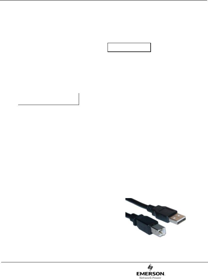
While it is possible to program the controller from the keypad, most users will find it more efficient to use a laptop computer, an A/B USB cable (see Figure 1), and the free Utility Software available from the 336/337 website. In the Designer’s Reference Handbook are directions for installing the software, connecting the controller to the laptop, and making changes to the settings.
Figure 1. A/B USB cable for programming controller.
Page 4 |
ASCO Power Technologies |
381333-427 A |
Operator’s Manual |
ASCO 336 / 337 |
Functional Test
The functional test consists of three checks: manual operation, voltage checks, and electrical operation.
NOTICE
Do these checks in the order presented to avoid damaging the transfer switch.
1 – Manual Operation
A maintenance handle is provided on the transfer switch for maintenance purposes only. Manual operation of the transfer switch should be checked before it is energized (before it is operated electrically). Note the contact position indicators.
! WARNING
Do not manually operate the transfer switch until all power sources are disconnected: open both generator circuit breakers and all load circuit breakers.
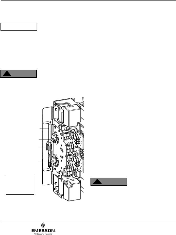
Left side of the transfer switch
Maintenance handle
Generator 2 contact shaft hub
Clip
Generator 1 contact shaft hub
Hubs shown with Generator 1 source contacts open and Generator 2 source contacts closed.
Figure 2. J-design transfer switch maintenance handle.
1.After deenergizing both power sources, open the enclosure door. Locate and remove the maintenance handle. Select either H-design or G-design. See Figures 2 and 3.
J & H-design see Figures 2 & 3
The maintenance handle is stored in clips on the left side of the transfer.
G-design see Figure 4
The maintenance handle, hub, and pin are stored on the center frame of the transfer.
2.Install the handle into the hole in the molded hub. Move the handle up or down as shown to manually operate the transfer switch to close and reopen the contacts. It should operate smoothly without any binding. If it does not, check for shipping damage or construction debris.
J & H-design see Figures 2 & 3
The transfer switch has two contact shaft hubs Install the maintenance handle into the hole in the molded hub. The upper hub operates the Generator 2 contacts. The lower hub operates the Generator 1 contacts.
G-design see Figure 4
Install the hub (with pin) onto the shaft. Insert the maintenance handle into the side hole in the hub. Push in the shaft to operate the Generator 1 contacts. Pull out the shaft to operate the Generator 2 contacts.
3.After checking manual operation, return all transfer switch contacts to the open position. Generator 1 and Generator 2 contacts must be open. Check contact position indicators.
4.Remove the maintenance handle and store it on the transfer switch in the place provided.
J & H-design see Figures 2 & 3
Store the maintenance handle in the clips on the left side of the transfer.
G-design see Figure 4
Store the maintenance handle, hub, and pin on the center frame of the transfer.
Note: If Generator 1 and Generator 2 connections are reversed this operation is also reversed.
! WARNING
Verify that the maintenance handle has been removed and stored properly before electrically operating the transfer switch.
381333-427 A |
ASCO Power Technologies |
Page 5 |
 Loading...