


 Loading...
Instruction Manual
CI-ControlWave EPAC
Part: D301384X012
March, 2011
ControlWave ExpressPAC
ControlWave ExpressPAC
(Process Automation Controller / Remote Terminal Unit)
Remote Automation Solutions
www.EmersonProcess.com/Remote
IMPORTANT! READ INSTRUCTIONS BEFORE STARTING!
Be sure that these instructions are carefully read and understood before any operation is attempted. Improper use of this device in some applications may result in damage or injury. The user is urged to keep this book filed in a convenient location for future reference.
These instructions may not cover all details or variations in equipment or cover every possible situation to be met in connection with installation, operation or maintenance. Should problems arise that are not covered sufficiently in the text, the purchaser is advised to contact Emerson Process Management, Remote Automation Solutions division (RAS) for further information.
EQUIPMENT APPLICATION WARNING
The customer should note that a failure of this instrument or system, for whatever reason, may leave an operating process without protection. Depending upon the application, this could result in possible damage to property or injury to persons. It is suggested that the purchaser review the need for additional backup equipment or provide alternate means of protection such as alarm devices, output limiting, fail-safe valves, relief valves, emergency shutoffs, emergency switches, etc. If additional information is required, the purchaser is advised to contact RAS.
RETURNED EQUIPMENT WARNING
When returning any equipment to RAS for repairs or evaluation, please note the following: The party sending such materials is responsible to ensure that the materials returned to RAS are clean to safe levels, as such levels are defined and/or determined by applicable federal, state and/or local law regulations or codes. Such party agrees to indemnify RAS and save RAS harmless from any liability or damage which RAS may incur or suffer due to such party's failure to so act.
ELECTRICAL GROUNDING
Metal enclosures and exposed metal parts of electrical instruments must be grounded in accordance with OSHA rules and regulations pertaining to "Design Safety Standards for Electrical Systems," 29 CFR, Part 1910, Subpart S, dated: April 16, 1981 (OSHA rulings are in agreement with the National Electrical Code).
The grounding requirement is also applicable to mechanical or pneumatic instruments that include electrically operated devices such as lights, switches, relays, alarms, or chart drives.
EQUIPMENT DAMAGE FROM ELECTROSTATIC DISCHARGE VOLTAGE
This product contains sensitive electronic components that can be damaged by exposure to an electrostatic discharge (ESD) voltage. Depending on the magnitude and duration of the ESD, this can result in erratic operation or complete failure of the equipment. Read supplemental document S14006 for proper care and handling of ESD-sensitive components.
Remote Automation Solutions
A Division of Emerson Process Management
1100 Buckingham Street, Watertown, CT 06795
Telephone (860) 945-2200
Emerson Process Management
Training
GET THE MOST FROM YOUR EMERSON
INSTRUMENT OR SYSTEM
Avoid Delays and problems in getting your system on-line
Minimize installation, start-up and maintenance costs.
Make the most effective use of our hardware and software.
Know your system.
As you know, a well-trained staff is essential to your operation. Emerson offers a full schedule of classes conducted by full-time, professional instructors. Classes are offered throughout the year at various locations. By participating in our training, your personnel can learn how to install, calibrate, configure, program and maintain your Emerson products and realize the full potential of your system.
For information or to enroll in any class, go to http://www.EmersonProcess.com/Remote and click on “Educational Services” or contact our training department in Watertown at (860) 945-2200.
This page is intentionally left blank

ControlWave ExpressPAC Instruction Manual (CI-ControlWave EPAC)
Contents
Chapter 1 – Introduction |
1-1 |
|
1.1 |
Scope of the Manual ................................................................................................................. |
1-2 |
1.2 |
Physical Description.................................................................................................................. |
1-2 |
1.3 |
CPU/System Controller Board .................................................................................................. |
1-4 |
1.4 |
Power Options........................................................................................................................... |
1-6 |
1.5 |
I/O Options ................................................................................................................................ |
1-6 |
1.6 |
Software Tools .......................................................................................................................... |
1-7 |
Chapter 2 – Installation |
2-1 |
||
2.1 |
Site Considerations ................................................................................................................... |
2-1 |
|
|
2.1.1 Class I, Div 2 Installation Considerations...................................................................... |
2-3 |
|
2.2 |
Installation Overview ................................................................................................................. |
2-3 |
|
|
2.2.1 |
Mounting the Housing ................................................................................................... |
2-4 |
|
2.2.2 |
Grounding the Housing ................................................................................................. |
2-9 |
2.3 |
Configuring the CPU/System Controller Board....................................................................... |
2-10 |
|
|
2.3.1 Setting DIP Switches on the CPU/System Controller Board ...................................... |
2-11 |
|
|
2.3.2 Setting Jumpers on the CPU/System Controller Board .............................................. |
2-13 |
|
|
2.3.3 |
General Wiring Guidelines .......................................................................................... |
2-14 |
|
2.3.4 Wiring Power to the CPU/System Controller Board.................................................... |
2-14 |
|
|
2.3.5 Mounting the Solar Panel............................................................................................ |
2-18 |
|
|
2.3.6 Connections to RS-232 Serial Port(s) on the CPU/System Controller Board............. |
2-21 |
|
|
2.3.7 Connections to the COM3 (RS-485/RS-232) Serial Port on the CPU/System Controller |
||
|
|
Board ......................................................................................................................... |
2-26 |
|
2.3.8 Connections to the Ethernet Port on the CPU/System Controller Board.................... |
2-28 |
|
2.4 |
Radios and Modems ............................................................................................................... |
2-29 |
|
2.5 |
Optional Display/Keypads ....................................................................................................... |
2-29 |
|
Chapter 3 – I/O Configuration and Wiring |
3-1 |
|
3.1 |
I/O Options ................................................................................................................................ |
3-1 |
3.2 |
Process I/O Board..................................................................................................................... |
3-2 |
|
3.2.1 Setting Jumpers on the Process I/O Board................................................................... |
3-2 |
3.3 |
3.2.2 Setting DIP Switches on the Process I/O Board........................................................... |
3-2 |
I/O Wiring .................................................................................................................................. |
3-4 |
|
|
3.3.1 Non-Isolated Discrete Inputs (DI) on TB2 and TB3 of Process I/O Board.................... |
3-6 |
|
3.3.2 Non-Isolated Discrete Outputs (DO) on TB3 of Process I/O Board.............................. |
3-7 |
|
3.3.3 Non-Isolated Analog Inputs (AI) on TB6 of Process I/O Board..................................... |
3-8 |
|
3.3.4 Non-Isolated Analog Output (AO) on TB7 of Process I/O Board.................................. |
3-9 |
|
3.3.5 Non-Isolated Pulse Counter/Discrete Inputs on TB5 of CPU/System Controller Bd .. |
3-10 |
|
3.3.6 Non-Isolated High Speed Counter/ Discrete Inputs on TB4 of Process I/O Bd.......... |
3-11 |
|
3.3.7 Resistance Temperature Device (RTD) Inputs on CPU/System Controller Board..... |
3-12 |
|
3.3.8 Connections to a Bristol Model 3808 Transmitter....................................................... |
3-14 |
Chapter 4 – Operation |
|
4-1 |
|
|
4.1 |
Powering Up/Powering Down the ControlWave ExpressPAC.................................................. |
4-1 |
|
|
4.2 |
Communicating with the ControlWave ExpressPAC ................................................................ |
4-2 |
|
|
|
4.2.1 Default Comm Port Settings |
.......................................................................................... |
4-2 |
|
|
4.2.2 Collecting Data from the ControlWave ....................................................ExpressPAC |
4-2 |
|
|
4.3 |
Creating and Downloading an Application ...........................................(ControlWave Project) |
4-3 |
|
|
|
|
|
|
|
Issued Mar-2011 |
Contents |
v |
||

ControlWave ExpressPAC Instruction Manual (CI-ControlWave EPAC)
4.4 Creating and Maintaining Backups ........................................................................................... |
4-3 |
|
4.4.1 Creating a Zipped Project File (*.ZWT) For Backup ..................................................... |
4-4 |
|
4.4.2 |
Saving Flash Configuration Parameters (*.FCP) .......................................................... |
4-5 |
4.4.3 |
Backing up Data............................................................................................................ |
4-6 |
Chapter 5 – Service and Troubleshooting |
5-1 |
||
5.1 |
Upgrading Firmware.................................................................................................................. |
5-2 |
|
5.2 |
Removing or Replacing Components ....................................................................................... |
5-5 |
|
|
5.2.1 Accessing Modules for Testing ..................................................................................... |
5-5 |
|
|
5.2.2 |
Removing/Replacing the CPU/System Controller Board and the Process I/O Board ..5-5 |
|
|
5.2.3 Removing/Replacing the Primary Battery System........................................................ |
5-6 |
|
|
5.2.4 Removing/Replacing the Backup Battery ..................................................................... |
5-7 |
|
|
5.2.5 Enabling / Disabling the Backup Battery....................................................................... |
5-8 |
|
|
5.2.6 Removing/Replacing the Case-Mounted Radio or Modem .......................................... |
5-9 |
|
5.3 |
General Troubleshooting Procedures ....................................................................................... |
5-9 |
|
|
5.3.1 |
Checking LEDs ............................................................................................................. |
5-9 |
|
5.3.2 Status Messages on LCD Display .............................................................................. |
5-10 |
|
|
5.3.3 |
WINDIAG Diagnostic Utility......................................................................................... |
5-11 |
|
5.3.4 |
Available Diagnostics.................................................................................................. |
5-12 |
5.4 |
Core Updump.......................................................................................................................... |
5-15 |
|
5.5 |
Calibration Checks .................................................................................................................. |
5-17 |
|
Appendix A – Special Instructions for Class I, Division 2 Hazardous Locations |
A-1 |
||
Appendix Z – Sources for Obtaining Material Safety Data Sheets (MSDS) |
Z-1 |
||
Index |
|
|
IND-1 |
vi |
Contents |
Issued Mar-2011 |

ControlWave ExpressPAC Instruction Manual (CI-ControlWave EPAC)
Chapter 1 – Introduction
This manual focuses on the hardware aspects of the ControlWave ExpressPAC Process Automation Controller/Remote Terminal Unit (RTU). For information about the software used with the ControlWave ExpressPAC, refer to Getting Started with ControlWave Designer (D5085), the ControlWave Designer Programmer’s Handbook (D5125), and the online help in ControlWave Designer.
This chapter provides an overview of the ControlWave ExpressPAC and its components and details the structure of this manual
In This Chapter
1.1 |
Scope of the Manual........................................................................ |
1-2 |
1.2 |
Physical Description ........................................................................ |
1-2 |
1.3 |
CPU/System Controller Board......................................................... |
1-4 |
1.4 |
Power Options ................................................................................. |
1-6 |
1.5 |
I/O Options....................................................................................... |
1-6 |
1.6 |
Software Tools................................................................................. |
1-7 |
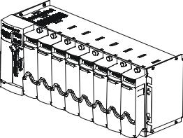
ControlWave ExpressPAC is designed to perform as the ideal platform for remote site automation, measurement, and data management in process control and manufacturing. It can serve as a process automaticn controller or remote terminal unit (RTU). Typical process inputs used by the ControlWave ExpressPAC are pressure, flow, level, temperature and frequency input [typically used for positive displacement (PD)], turbine, or ultrasonic meters. In some cases, inputs may also be derived from external multivariable transmitters using either the BSAP or Modbus protocols. Emerson provides the ControlWave ExpressPAC in a NEMA 3R rated enclosure which allows operation in an un-protected outdoor environment.
Features ControlWave ExpressPAC has the following key features:
Exceptional performance and low power consumption through use of the ARM microprocessor
Very low power consumption to minimize costs of integrated solar panel / battery power systems
Three CPU / System Controller board configurations (see Table 1- 1.)
Three process I/O board configurations (see Table 1-2.)
Two RS-232 and one RS-232/RS-485 asynchronous serial communication ports
Optional 10/100 MB Ethernet port
Broad selection of modem and wireless communication options
Optional display or display/keypad
Revised Mar-2011 |
Introduction |
1-1 |

ControlWave ExpressPAC Instruction Manual (CI-ControlWave EPAC)
Wide operating temperature range: (–40 to +70 C) (–40 to 158 F)
Battery backup for Static RAM (SRAM) and real-time clock.
Nonincendive Class I, Division 2 (Groups C and D) Hazardous Location approvals - See Appendix A.
Cost-effective for small RTU/process controller applications.
1.1Scope of the Manual
This manual contains the following chapters:
Chapter 1 |
Provides an overview of the hardware and |
Introduction |
general specifications for the ControlWave |
|
ExpressPAC. |
Chapter 2 |
Provides information on mounting the |
Installation |
ControlWave ExpressPAC and setting CPU |
|
jumpers and switches. |
Chapter 3 |
Provides general information on wiring the |
I/O Configuration |
process I/O points. |
Chapter 4 |
Provides information on day-to-day operation of |
Operation |
the ControlWave ExpressPAC. |
Chapter 5 Service and |
Provides information on service and |
Troubleshooting |
troubleshooting procedures. |
1.2 Physical Description
The ControlWave ExpressPAC includes the following major components:
Enclosure with a local communication port and LCD display/keypad.
CPU/System Controller Board (SCB) – See Section 1.3
Optional process I/O board – See Section 1.5
Internal mounting brackets and battery
Optional RTD probe– See Section 1.5
Radio/modem options
1-2 |
Introduction |
Revised Mar-2011 |
ControlWave ExpressPAC Instruction Manual (CI-ControlWave EPAC)
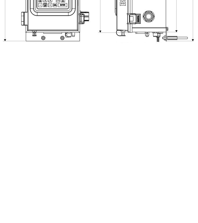
Figure 1-1. ControlWave ExpressPAC Enclosure shown with wall/panel mounting brackets and dualbutton display/keypad
Revised Mar-2011 |
Introduction |
1-3 |

ControlWave ExpressPAC Instruction Manual (CI-ControlWave EPAC)
Enclosure The ControlWave ExpressPAC enclosure is a standard NEMA 3R rated fiberglass enclosure. The enclosure consists of the body and the front cover. A continuous gasket seals the unit when you close the front cover. Two latches on the enclosure’s right side secure the cover.
The enclosure includes a weatherproof connector (local port) mounted to the bottom of the cover and connected internally to RS-232 COM port 1.
The enclosure includes a display or display/keypad for an operator or technician to view process values locally.
Internal Mounting Internal mounting brackets support the various system components, Brackets and Battery such as the battery, CPU/System Controller and Process I/O boards,
and the radio/modem option. These components attach to the one piece mounting bracket which is secured to the inner rear wall of the enclosure. A factory-supplied radio or modem mounts in front of the battery on a battery cover/radio mounting plate.
You can order the ControlWave Express from the factory with one of the following power options:
Single 6V lithium battery
Dual 12V lithium battery pack
6V, 7AH lead acid battery used with a 1W, 6V solar panel.
6V, 7AH lead acid battery used with a 5W, 6V solar panel.
12V, 7AH lead acid battery used with a 5W, 12V solar panel.
No battery; user-supplied power source.
Radio/Modem You can order the ControlWave ExpressPAC with a factory-installed modem or spread spectrum radio. The unit supports a variety of MDS and FreeWave radios and modems. Contact Emerson Remote Automation Solutions for more information.
1.3 CPU/System Controller Board
The CPU (central processing unit) and System Controller Board (SCB) contains the ControlWave ExpressPAC CPU, I/O monitor/control, memory, and communication functions.
The CPU/System Controller board includes:
Sharp LH7A400 System-on-Chip ARM microprocessor with 32-bit ARM9TDMI Reduced Instruction Set Computer (RISC) core, with a system clock speed of either 14 MHz or 33 MHz.
two RS-232 communication ports
one communication port configurable by jumpers as either RS-232 or RS-485
optional 10/100baseT Ethernet port (See Table 1-1)
2 MB of battery backed Static RAM (SRAM),
1-4 |
Introduction |
Revised Mar-2011 |
ControlWave ExpressPAC Instruction Manual (CI-ControlWave EPAC)
512KB boot/downloader FLASH,
8MB simultaneous read/write FLASH memory
Board Variations The CPU/System Controller board has three basic variations:
Table 1-1. CPU/System Controller board Variations
CPU |
Nominal |
Ethernet |
Solar |
Auxiliary |
RTD Input? |
|
Input |
Port? |
Regulator |
Power |
|
|
Power |
? |
Output? |
|
|
|
|
|
|||
14MHz |
+6Vdc or |
No |
Yes |
Yes |
Yes. Connects to |
ultra low |
+12Vdc |
|
|
|
100-ohm |
power |
|
|
|
|
platinum bulb. |
|
|
|
|
|
Uses DIN 43760 |
|
|
|
|
|
curve. |
33MHz |
+12V or |
No |
Yes |
Yes |
No |
low |
+24Vdc |
|
|
|
|
power |
|
|
|
|
|
33MHz |
+12V or |
Yes |
No |
No |
Yes (same as |
|
+24Vdc |
|
|
|
ultra low power) |
Note: Each of the variants shown in Table 1-1 may be ordered with or without special gas calculation firmware.
CPU Backup Battery The CPU/System Controller board has a coin cell socket that accepts a 3.0V, 300 mA-hr lithium battery. This 3.0V battery provides backup power for the real-time clock and the system’s Static RAM (SRAM).
CPU Memory There are several different types of memory used by the CPU:
Boot/Downloader FLASH
Boot/download code is contained in a single 512 Kbyte FLASH chip. Boot FLASH also holds the value of soft switches, audit/archive file configurations, and user account and port information.
FLASH Memory
The ControlWave ExpressPAC includes 8 MB of FLASH memory. The FLASH memory holds the system firmware and the boot project. Optionally FLASH memory also stores the zipped ControlWave project (*.zwt), user files, and historical data (audit/archive files).The FLASH does not support hardware write protection.
System Memory (SRAM)
The ControlWave ExpressPAC has 2 MB of static random access memory (SRAM). During power loss periods, SRAM enters data
Revised Mar-2011 |
Introduction |
1-5 |

ControlWave ExpressPAC Instruction Manual (CI-ControlWave EPAC)
retention mode (powered by a backup 3.0V lithium battery). Critical system information that must be retained during power outages or when the system has been disabled for maintenance is stored here. This includes the last states of all I/O points, audit/archive historical data (if not stored in FLASH), the values of any variables marked RETAIN, the values of any variables assigned to the static memory area, and any pending alarm messages not yet reported.
1.4 Power Options
You can power the ControlWave ExpressPAC by:
factory-supplied rechargeable 6/12V lead acid battery (used in conjunction with a solar panel),
factory-supplied single or dual lithium battery pack
user-supplied bulk (nominal +6Vdc, +12Vdc or +24Vdc) power supply.
If you connect solar panels to rechargeable battery systems to power the ControlWave ExpressPAC, there is a secondary power input you can use to provide power if there is no power from the solar panel/battery system.
1.5 I/O Options
ControlWave ExpressPAC comes with the following standard I/O
2 Pulse Counter Inputs with a 1 second scan rate (can be configured as discrete inputs (DI))
The 14 MHz CPU and 33 MHz CPU with Ethernet also include a Resistance Temperature Device (RTD) probe.
In addition, three different versions of the optional process I/O board are available:
Table 1-2. Process I/O Configurations
Type |
Discrete |
Discrete |
Discrete |
High Speed |
Analog |
Analog |
|
Input / |
Input (DI) |
Output |
Counter |
Input (AI) |
Output |
|
Output |
|
(DO) |
(HSC) |
|
(AO) |
|
(DI/DO) |
|
|
|
|
|
A |
2 |
4 |
2 |
2 |
|
|
B |
2 |
4 |
2 |
2 |
3 |
|
C |
2 |
4 |
2 |
2 |
3 |
1 |
1-6 |
Introduction |
Revised Mar-2011 |
ControlWave ExpressPAC Instruction Manual (CI-ControlWave EPAC)
1.6Software Tools
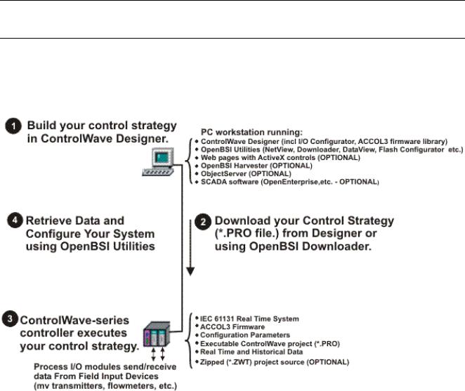
The ControlWave programming environment consists of a set of integrated software tools which allow you to create, test, implement, and download complex control strategies for use with the ControlWave ExpressPAC. Figure 1-2 graphically presents the programming environment.
Figure 1-2. ControlWave Programming Environment
The tools which make up the programming environment include:
ControlWave Designer is your load-building package. It offers several different methods for you to create control strategy programs that run in your ControlWave ExpressPAC. You can use pre-made function blocks, ladder logic, or structured languages. The resulting process control strategy programs (called projects) are fully compatible with IEC 61131 standards. For information on ControlWave Designer, see the Getting Started with ControlWave Designer manual (document D5085), and the ControlWave Designer Programmer’s Handbook (document D5125).
The I/O Configurator, accessible via a menu item in ControlWave Designer, allows you to define process I/O in the ControlWave and configure the individual mapping of I/O points for discrete and analog inputs and outputs. For information on the I/O Configurator see the ControlWave Designer Programmer’s Handbook (document D5125).
Revised Mar-2011 |
Introduction |
1-7 |

ControlWave ExpressPAC Instruction Manual (CI-ControlWave EPAC)
The ACCOL3 Firmware Library, available within ControlWave Designer, includes a series of ControlWave-specific function blocks. These pre-programmed function blocks let you accomplish various tasks common to most user applications including alarming, historical data storage, as well as process control algorithms such as PID control. For information on individual function blocks, see the online help within ControlWave Designer.
OpenBSI Utilities provides a set of programs that allow you to configure a communication network of ControlWave controllers, download files to the controllers, and collect data from the network. OpenBSI also exports data from the network to a SCADA/host package, such as OpenEnterprise. For information on configuring OpenBSI communications, see the OpenBSI Utilities Manual (document D5081).
OpenBSI Harvester is a special add-on package that allows scheduled data collections from large networks. For information on the Harvester, see the OpenBSI Harvester Manual (document D5120).
A series of web page controls are available for retrieval of real-time data values and communication statistics. These controls utilize ActiveX technology and are called through a set of fixed web pages, compatible with Microsoft® Internet Explorer. Alternatively, developers can place the controls in third-party ActiveX compatible containers such as Visual BASIC or Microsoft® Excel. For information on the ActiveX controls, see the Web_BSI Manual (document D5087).
User-defined web pages - If desired, you can use the ActiveX web controls in your own user-defined web pages you can store at the PC to provide a customized human-machine interface (HMI).
Flash Configuration Utility – Parameters such as the BSAP local address, IP address, etc. are set using the Flash Configuration Utility, accessible via OpenBSI LocalView, NetView, or TechView. For information on the Flash Configuration Utility, see Chapter 5 of the OpenBSI Utilities Manual (document D5081).
Communication In addition to the Bristol Synchronous/Asynchronous Protocol
Protocols (BSAP), ControlWave supports communications using:
Internet Protocol (IP) - You can use an Ethernet port or use a serial port with serial IP using Point-to-Point Protocol (PPP).
Other supported protocols include: Modbus, Allen-Bradley DF1, CIP, DNP3, and Hex Repeater. See the ControlWave Designer online help for details and restrictions.
1-8 |
Introduction |
Revised Mar-2011 |

ControlWave ExpressPAC Instruction Manual (CI-ControlWave EPAC)
Chapter 2 – Installation
This chapter discusses the physical configuration of the ControlWave ExpressPAC, considerations for installation, and instructions for setting switches and jumpers.
In This Chapter
2.1 |
Site Considerations.......................................................................... |
2-1 |
|
|
2.1.1 Class I, Div 2 Installation Considerations............................. |
2-3 |
|
2.2 |
Installation Overview........................................................................ |
2-3 |
|
|
2.2.1 |
Mounting the Housing .......................................................... |
2-4 |
|
2.2.2 |
Grounding the Housing ........................................................ |
2-9 |
2.3 |
Configuring the CPU/System Controller Board ............................. |
2-10 |
|
|
2.3.1 Setting DIP Switches on CPU/System Controller Board.... |
2-11 |
|
|
2.3.2 Setting Jumpers on the CPU/System Controller Board ..... |
2-13 |
|
|
2.3.3 |
General Wiring Guidelines ................................................. |
2-14 |
|
2.3.4 Wiring Power to the CPU/System Controller Board........... |
2-14 |
|
|
2.3.5 Mounting the Solar Panel................................................... |
2-18 |
|
|
2.3.6 Connections to RS-232 Serial Port(s) on the CPU/System |
||
|
|
Controller Board................................................................ |
2-21 |
|
2.3.7 Connections to the COM3 (RS-485/RS-232) Serial Port on the |
||
|
|
CPU/System Controller Board.......................................... |
2-26 |
|
2.3.8 Connections to the Ethernet Port on the CPU/System Controller |
||
|
|
Board ................................................................................ |
2-28 |
2.4 |
Radios and Modems...................................................................... |
2-29 |
|
2.5 |
Optional Display/Keypads.............................................................. |
2-29 |
|
2.1 Site Considerations
|
When choosing an installation site, check all clearances. Ensure that you |
|
can open the ControlWave ExpressPAC cover (hinged on the left side) |
|
for wiring and service. If present, make sure the optional |
|
display/keypad is accessible and visible. See Figure 2-2 for a |
|
dimensional drawing of the NEMA enclosure. |
|
Ensure adequate clearance for the solar panel (if required). |
|
The ControlWave ExpressPAC comes in an enclosure/chassis that you |
|
can mount to a panel, a wall or a 2 inch vertical pipe. The ControlWave |
|
ExpressPAC is designed to operate in an outdoor un-protected Class I |
|
Division 2, Groups C & D environment with a nonincendive rating (see |
|
Appendix A). |
Caution |
To ensure safe use of this product, please review and follow the |
instructions in the following supplemental documentation: |
|
|
Supplement Guide - ControlWave Site Considerations for |
|
Equipment Installation, Grounding, and Wiring (S1400CW) |
|
ESDS Manual – Care and Handling of PC Boards and ESD |
|
Sensitive Components (S14006) |
Revised Mar-2011 |
Installation |
2-1 |
ControlWave ExpressPAC Instruction Manual (CI-ControlWave EPAC)
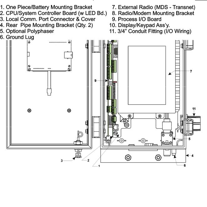
Figure 2-1. ControlWave ExpressPAC Component Identification
2-2 |
Installation |
Revised Mar-2011 |

ControlWave ExpressPAC Instruction Manual (CI-ControlWave EPAC)
Specifications for Temperature, Humidity and Vibration
See document 420DS-7d available on our website for detailed technical specifications for temperature, humidity, and vibration for the ControlWave ExpressPAC.
Ensure that the ambient temperature and humidity at the installation site remains within these specifications. Operation beyond the specified ranges could cause output errors and erratic performance. Prolonged operation under extreme conditions could also result in failure of the unit.
Check the mounted enclosure, panel, or pipe for mechanical vibrations. Make sure that the ControlWave ExpressPAC is not exposed to a level of vibration that exceeds that provided in the technical specifications.
2.1.1Class I, Div 2 Installation Considerations
Underwriters Laboratories (UL) lists the ControlWave ExpressPAC as non-incendive and suitable only for use in Class I, Division 2, Groups C, and D hazardous locations and non-hazardous locations. Read this chapter and Appendix A carefully before you install a ControlWave ExpressPAC in a hazardous location.
Perform all power and I/O wiring in accordance with Class I, Division 2 wiring methods as defined in Article 501-4 (b) of the National Electrical Code, NFPA 70 (for installations within the United States) or as specified in Section 18-152 of the Canadian Electrical Code (for installation in Canada).
 WARNING EXPLOSION HAZARD
Substitution of components may impair suitability for use in Class I, Division 2 Groups C and D environments.
When the ControlWave ExpressPAC is situated in a hazardous location, turn off power before servicing or replacing the unit and before installing or removing I/O wiring.
Do not disconnect equipment unless the power is switched off or the area is known to be non-hazardous.
2.2 Installation Overview
ControlWave ExpressPAC ships from the factory with all components wired and mounted, except for the unit’s solar panel and primary battery; these items are shipped separately.
Installing a ControlWave ExpressPAC involves several general steps:
1.Installing and configuring the hardware. This includes:
a)Mounting the chassis on a panel, wall, or vertical pipe. (See
Section 2.2.1)
Revised Mar-2011 |
Installation |
2-3 |

ControlWave ExpressPAC Instruction Manual (CI-ControlWave EPAC)
b)Enabling the backup battery by setting jumper W3 on the CPU/System Controller board to position 1 to 2. (See Section 2.3.2)
b)Setting switches and jumpers on the CPU/System Controller board (see Section 2.3.1 and Section 2.3.2) and on the Process I/O board (see Section 3.2.1 and Section 3.2.2) and placing both boards (as a single assembly) into the chassis.
d)Connecting communication cables, including a cable to a 3808 transmitter, if required. (See Sections 2.3.6, 2.3.7, 2.3.8, and
3.3.8.)
e)Wiring I/O. (See Section 3.3)
f)Installing a ground wire between the enclosure ground lug and a known good Earth ground. (See Section 2.2.2)
g)Connecting the RTD probe (if required). (See Section 3.3.7)
h)Installing the solar panel and rechargeable battery (if applicable).(See Section 2.3.5)
i)Wiring power to the unit. (See Section 2.3.4)
j)Turning on power. (See Section 4.1)
2.Installing PC-based software (ControlWave Designer).
3.Establishing communications.
4.Creating an application-specific control strategy (ControlWave project).
5.Creating application-specific web pages (optional).
6.Adding the ControlWave ExpressPAC to an OpenBSI network.
7.Downloading the application-specific ControlWave project into the ControlWave ExpressPAC.
Note: Steps 2 through 7 require that you install and use ControlWave Designer software on your PC. This manual focuses on hardware installation and preparation. Software installation and configuration is beyond the scope of this manual. Refer to the
Getting Started with ControlWave Designer Manual (D5085) and the ControlWave Designer Programmer’s Handbook
(D5125) for material related to software installation and use.
2.2.1Mounting the Housing
You must position the ControlWave ExpressPAC vertically. See Figure 2-2 for enclosure dimensions.
Make sure the front of the assembly is visible and you can open the front cover for service, installation, and so on. Ensure you can clearly see and use the optional LCD display/keypad.
2-4 |
Installation |
Revised Mar-2011 |
ControlWave ExpressPAC Instruction Manual (CI-ControlWave EPAC)
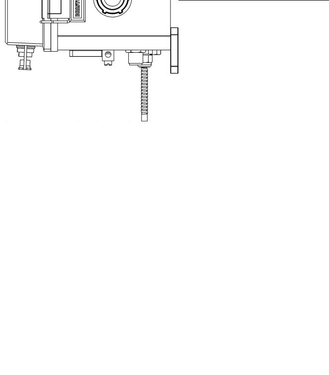
Figure 2-2. ControlWave ExpressPAC NEMA 3R Enclosure Dimensions
Mount the unit to a panel, a wall or to a vertical 2 inch pipe clamped at the rear of the unit using two clamps and four bolts. See Figure 2- 4 and Figure 2-5. If you mount to a pipe, it must be anchored in cement deep enough to conform to local building codes associated with frost considerations.
Revised Mar-2011 |
Installation |
2-5 |

ControlWave ExpressPAC Instruction Manual (CI-ControlWave EPAC)
If your unit requires a solar panel, you can mount it to the same 2 inch pipe that holds the controller. Make sure there is adequate clearance for the solar panel. For more information on the solar panel, see Section 2.3.5.
Only connect power wiring after the unit is mounted and properly grounded.
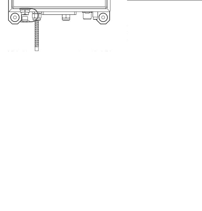
I/O wiring, external power wiring, RTD wiring, antenna cabling, and communication port cabling enters the bottom of the unit through conduit or special function fittings. (See Figure 2-3.) I/O wiring is routed through the left side of the unit (right when facing the front) via a ¾ inch conduit fitting.
Figure 2-3. ControlWave ExpressPAC Bottom View
.
2-6 |
Installation |
Revised Mar-2011 |
ControlWave ExpressPAC Instruction Manual (CI-ControlWave EPAC)
Figure 2-4. Side View of ControlWave ExpressPAC (Mounted to a 2” Pipe)
Revised Mar-2011 |
Installation |
2-7 |
ControlWave ExpressPAC Instruction Manual (CI-ControlWave EPAC)
Figure 2-5. Side View of ControlWave ExpressPAC (Wall or Panel Mounted)
2-8 |
Installation |
Revised Mar-2011 |

ControlWave ExpressPAC Instruction Manual (CI-ControlWave EPAC)
2.2.2 Grounding the Housing
The ControlWave ExpressPAC enclosure includes a ground lug that accommodates up to a #4 AWG wire size. Once you install the unit, run a ground wire between the enclosure’s ground lug and a known good Earth ground. For more information on grounding see the ControlWave Grounding Supplement (S1400CW):
Additional grounding guidelines include:
Use stranded copper wire (#4 AWG) to earth ground, and keep the length as short as possible.
Clamp or braze the ground wire to the ground bed conductor (typically a stranded copper AWG 0000 cable installed vertically or horizontally).
Using a high-wattage soldering iron, tin the ground wire with solder before you insert it into the chassis ground.
Run the ground wire so that any routing bend in the cable has a minimum radius of 12-inches below ground and 8-inches above ground.
Revised Mar-2011 |
Installation |
2-9 |
ControlWave ExpressPAC Instruction Manual (CI-ControlWave EPAC)
2.3 Configuring the CPU/System Controller Board
To configure the CPU/System Controller board, you need to set some switches and jumpers.
Solar Pwr. In + |
1 |
|
|
|
|
GND 2 |
|
|
|
Power In + |
3 |
|
|
|
|
GND |
4 |
|
Power |
Aux. Power Out + |
5 |
|
||
|
|
|||
|
GND 66 |
|
|
|
Sec. Battery Input |
1 |
|
|
|
Input |
GND |
2 |
|
Power |
DCD |
1 |
|
|
|
Input |
RXD 2 |
|
|
|
Output |
TXD |
3 |
6 |
1 |
Output |
DTR |
4 |
|
|
|
COM1 |
|||
|
GND 5 |
|
||
Input |
DSR |
6 |
9 |
5 RS-232 |
Output |
RTS 7 |
|
|
|
Input |
CTS |
8 |
|
|
Input |
DCD |
1 |
|
|
Input |
RXD 2 |
|
|
|
Output |
TXD 3 |
|
COM2 |
|
Output |
DTR |
4 |
|
RS-232 |
Input |
GND 5 |
|
|
|
DSR |
6 |
|
|
|
Output |
RTS 7 |
|
|
|
Input |
CTS |
8 |
|
|
Receive LED |
|
|
|
|
|
|
|
|
10/100 |
|
|
|
|
Base-T |
|
|
|
|
Ethernet |
Transmit LED |
|
|
Port |
|
1 = Idle |
|
|
1NO |
|
2 = Watchdog}CR1 |
2 |
|||
|
|
|
1 |
|
|
|
|
2 |
|
Configuration |
3 |
|
||
4 |
|
|||
Options |
|
5 |
|
|
|
Switch |
|
7 6 |
|
|
|
|
8 |
|
|
|
|
NOTE: Ultra Low Power & Low Power |
|||
|
|
|
|
|
CPU/System Controller Bds. |
|
|
|
|
|
|
Don’t have an Ethernet Port. |
|
|
|
|
|
|
Solar Pwr. In and Aux. Power Out |
|
|
|
|
F3 |
|
are not available on units equipped |
|
|
|
|
|
with an Ethernet Port. |
||
|
|
|
|
|
||
|
|
|
|
|
Do Not Connect a 24V Solar Panel |
|
|
|
|
|
|
to Connector TB1-1 & TB1-2! |
|
|
|
|
|
|
W1 - 1-2 |
= COM1 CTS from Port |
|
|
|
|
|
2-3 |
= COM1 CTS to RTS |
|
|
|
|
|
W2 - 1-2 |
= COM2 CTS from Port |
|
|
|
|
|
2-3 |
= COM2 CTS to RTS |
|
|
|
|
|
W3 - 1-2 |
= Battery Enabled |
|
|
|
|
|
2-3 |
= Battery Disabled |
|
|
|
|
|
W5 - 1-2 |
= 12/24V Power Supply |
|
|
|
|
|
2-3 |
Shut-down Hysterisis |
|
|
|
|
|
= 6V Power Supply |
|
|
|
|
|
W1 |
|
Shut-down Hysterisis |
|
|
W18 |
|
W6 - 1-2 |
= 12V Power Supply |
|
|
|
|
|
|||
3 |
2 |
1 |
|
|
|
Shut-down |
|
|
2-3 |
= 6/24V Power Supply |
|||
|
|
|
|
|
||
|
|
COM1 |
|
|
|
Shut-down |
|
|
|
|
|
|
|
|
|
RS-232 |
|
|
|
|
TRG |
|
|
|
|
||
XD |
|
N |
|
|
|
|
|
X |
|
|
W8 |
W6 |
|
|
|
D |
|
W2 |
||
|
D |
|
|
|
||
|
|
|
|
|
W7 |
W5 |
|
|
|
|
|
|
|
|
|
|
|
|
|
W7 - 1-2 = 12/24V Power Fail |
|
|
|
|
|
|
|
|
|
|
|
|
|
|
|
|
|
|
|
|
|
|
|
|
|
|
|
Trip Point Hysterisis |
|
|
|
|
RJ-45 |
|
|
|
|
|
|
2-3 = 6V Power Fail |
||
|
|
|
|
|
|
|
|
|
|
Trip Point Hysterisis |
|||
|
|
|
|
|
|
|
|
|
|
|
|
|
W8 - 1-2 = 12V Power Fail |
|
|
|
|
|
|
|
|
|
|
|
|
|
Trip Point |
|
|
|
|
|
|
|
|
|
|
|
|
|
2-3 = 6/24V Power Fail |
|
|
|
|
|
|
|
|
|
|
|
|
|
|
|
|
|
CR1 |
W3 |
|
|
|
|
Trip Point |
||||
1 |
|
|
|
|
|
|
|
|
|
|
W12 - W16 - 1-2 = COM3 RS-232 |
||
3 2 |
|
|
|
|
|
|
|
|
|
|
|
|
2-3 = COM3 RS-485 |
|
|
|
|
|
|
|
|
|
|
|
|
||
|
|
|
|
|
|
|
|
|
|
|
|
W17: 6/12V CPUs |
|
|
|
|
|
|
|
|
|
|
|
|
|||
|
|
|
|
|
|
|
|
|
|
|
|||
4 |
|
|
|
|
|
|
|
|
|
|
|
|
1-2 = 6V S.P. Charging System |
65 |
|
|
|
|
|
|
|
|
|
|
S1 |
2-3 = 12V S.P. Charging System |
|
8 7 |
|
|
|
|
|
|
|
|
|
|
|
|
W17: 12/24V CPUs |
|
|
|
|
|
|
|
|
|
|
|
|
||
|
|
|
|
|
|
|
|
|
|
|
|
||
|
|
|
|
|
|
|
|
|
|
|
|
1-2 = 12V S.P. Charging System |
|
|
|
|
|
|
|
|
|
|
|
|
|
|
2-3 = N/A |
|
|
|
|
|
|
|
|
|
|
|
|
|
|
|
Recovery |
|
||
|
Mode & |
|
|
|
|
COM./Status |
|
||
|
LEDs |
|
|
|
Input |
RXD+ |
1 |
|
|
Input |
RXD-/RXD 2 |
|
|
|
Output TXD-/TXD 3 |
|
|
||
Output |
TXD+ |
4 |
|
|
|
GND |
5 |
|
|
Input |
PULSE 1 |
1 |
|
|
|
|
|||
Input |
PULSE 2 |
2 |
|
|
|
GND |
3 |
|
|
Output |
PULSE |
4 |
|
|
|
PWR |
|
|
|
|
RTD EXC |
1 |
|
|
|
|
|
||
|
RTD+ |
2 |
|
|
|
RTD- |
3 |
|
|
|
|
|
|
|
O
N


 4 3 2 1
COM3
RS-232
RS-485
Pulse
Input
 4 3 2 1
W12 |
W13 |
W15 |
W14 |
RTD
Input
LCD/ RJ-45
Keypad
Note: W17 is N/A on 24V Systems
Do NOT connect a 24V Solar
Panel to TB-1 & TB-2! |
|
|
W18: COM1 connector |
|
|
selection |
|
|
1 to 2 = J4 active |
|
|
2 to 3 = J11 active |
|
|
SW3 - COM3 Config. |
|
|
RS-485 Receiver Biasing & Termination |
||
2-Wire, 4-Wire Selction |
J5 - COM3 |
|
|
|
Piggy-back |
J5 |
|
Radio Intf. |
J8 |
|
Emulation |
|
Header |
W17 |
|
NOTE: J7, J8, J9 Factory Use
J7
MSP430
JTAG
Header


 W16
W16
J9
PLD JTAG J3
Header
J3 - I/OBUS
Intf. to
CPU Board
CAUTION:
Damage WILL occur to
the CPU if the Ethernet P1  WE network is conected
to connector J2!
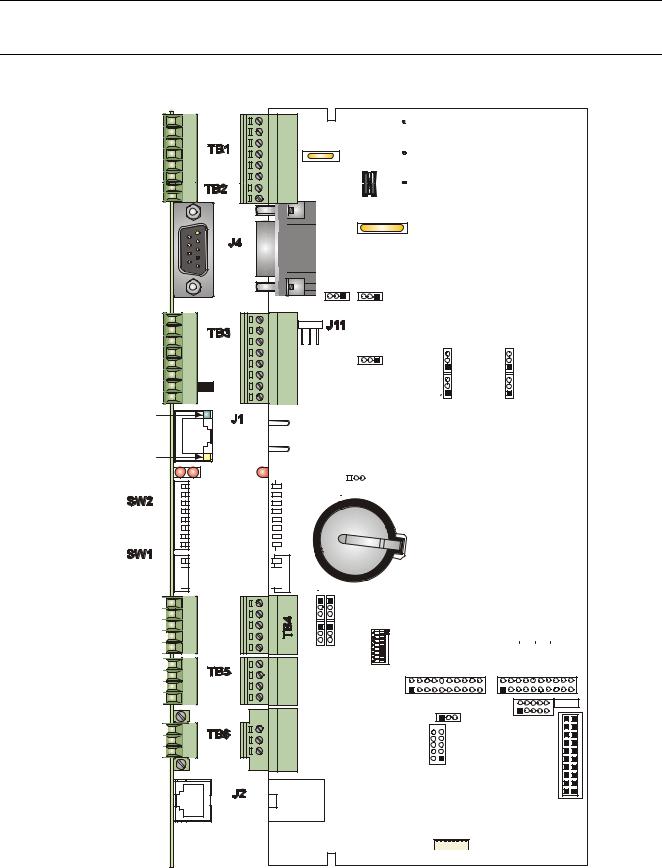
Figure 2-6. - CPU/System Controller Board Component I.D. Diagram
2-10 |
Installation |
Revised Mar-2011 |

ControlWave ExpressPAC Instruction Manual (CI-ControlWave EPAC)
2.3.1 Setting DIP Switches on the CPU/System Controller Board
Before you install the CPU/System Controller board, you must determine the settings for three banks of DIP switches. Refer to Figure 2-6 for the location of the DIP switch banks. Refer to Tables 2-1, 2-2, and 2-3 for an explanation of the DIP switch positions.
Note: Examine each bank of DIP switches carefully to note the switch direction for ON or OFF.
Table 2-1. CPU/System Controller Board Switch SW1
SW1 Setting |
Function |
Mode |
1 & 2 |
Recovery |
Recovery Mode = Both SW1-1 and SW1-2 ON or both |
|
Mode |
SW1-1 and SW1-2 OFF |
|
|
Local Mode = SW1-1 OFF and SW1-2 ON (Factory |
|
|
Default) |
3 |
Force |
Enables recovery mode. Values are: |
|
Recovery |
ON (enables recovery mode) |
|
Mode |
OFF (disables recovery mode). – This is the factory |
|
|
default. |
4 |
LED status |
ON (Enable Idle LED) |
|
|
OFF (Disable Idle LED) |
Table 2-2. CPU/System Controller Board Switch SW2
|
SW2 Setting |
Function |
Mode |
|
|
1 |
Watchdog |
Controls whether the system enters a watchdog state |
|
|
|
|
|
Enable |
when a crash or system hangup occurs and automatically |
||
|
|
|
restarts. Values are: |
|
|
|
|
|
ON (Enables watchdog circuit; factory default) |
|
|
|
|
|
OFF (Disables watchdog circuit and prevents automatic |
||
|
|
|
restart) |
|
|
2 |
Lock/Unlock |
Controls the ability to modify soft switches, other |
|
|
|
|
|
Soft Switches |
configurations, and flash files. Values are: |
|
|
|
|
|
ON (Unlocks soft switches and flash files; factory |
|
|
|
|
|
default). |
|
|
|
|
|
OFF (Locks soft switches, configurations, and flash files) |
||
3 |
Use/Ignore |
Controls the use of soft switches. Values are: |
|
|
|
|
|
Soft Switches |
ON (Enable user-defined soft switches configured in flash |
||
|
|
|
memory; factory default) |
|
|
|
|
|
OFF (Disable soft switch configuration and use factory |
||
|
|
|
defaults) |
|
|
|
|
|
Note: Setting both switch 3 and switch 8 to OFF (closed) |
||
|
|
|
sets all serial communication ports to 9600 bps |
|
|
|
|
|
operation. All serial communication ports must be |
||
|
|
|
set at 9600 bps before WINDIAG can perform |
|
|
|
|
|
communication tests. |
|
|
4 |
Core Updump Causes the ControlWave ExpressPAC to perform a core |
||||
|
|
|
updump, provided you have set the SW1 switches to allow |
||
|
|
|
recovery mode. Values are: |
|
|
|
|
|
|
|
|
Revised Mar-2011 |
|
Installation |
2-11 |
||

ControlWave ExpressPAC Instruction Manual (CI-ControlWave EPAC)
SW2 Setting |
Function |
Mode |
|
|
ON (Disables core updump; factory default) |
|
|
OFF Core updump |
5 |
SRAM Control |
Manages SRAM contents following a low power situation |
|
|
or a power outage. Values are: |
|
|
ON (Retain values in SRAM during restarts; factory |
|
|
default) |
|
|
OFF (Reinitialize SRAM) – Data in SRAM lost during |
|
|
power outage or re-start. |
6 |
System |
Allows a remote download of system firmware (on units |
|
Firmware |
equipped with boot PROM version 4.7 or higher and |
|
|
system PROM version 4.7 and higher). Values are: |
|
|
ON (Enable remote download of system firmware; factory |
|
|
default) |
|
|
OFF (Disable remote download of system firmware) |
7 |
N/A |
Not currently used. |
8 |
Enable |
Suspends normal operation and allows diagnostic |
|
WINDIAG |
routines. Values are: |
ON (Permits normal system operation, including the boot project, and disables the WINDIAG diagnostics from running; factory default)
OFF (Allow WINDIAG to run test; disable boot project and normal system operation.)
Note: Setting both switch 8 and switch 3 to OFF (closed) sets all communication ports to 9600 bps operation. All serial communication ports must be set at 9600 bps before WINDIAG can perform communication tests.
Note: Table 2-3 describes switch settings for RS-485 port operation. You may want to review Section 2.3.7 on RS-485 configuration before you set these switches.
Table 2-3. RS-485 Configuration Switch SW3
Switch |
Function |
Mode |
Setting |
|
|
1TX+ to RX+ Loopback / 2- wire
2TXto RXLoopback / 2- wire
3100 Ohm RX+ Termination
4100 Ohm RXTermination
5N/A
6N/A
ON (2-wire operation or loopback enabled)
OFF (4-wire operation and loopback disabled)
ON (2-wire operation or loopback enabled)
OFF (4-wire operation and loopback disabled)
ON (End nodes only) ON (End nodes only) Not currently used Not currently used
2-12 |
Installation |
Revised Mar-2011 |

ControlWave ExpressPAC Instruction Manual (CI-ControlWave EPAC)
Switch |
Function |
Mode |
Setting |
|
|
7 |
RX+ Bias (End Node) |
ON (4-wire = Both End nodes only; 2-wire= |
|
|
One end node only) |
|
|
OFF = No bias |
8 |
RXBias (End Node) |
ON (4-wire = Both End nodes only; 2-wire= |
|
|
One end node only) |
|
|
OFF = No bias |
2.3.2 Setting Jumpers on the CPU/System Controller Board
The CPU has several jumpers.
W1: COM1 CTS usage:
o 1-to-2 Installed = COM1 CTS source is from device. o 2-to-3 Installed = COM1 RTS to CTS loopback
W2: COM2 CTS usage:
o 1-to-2 Installed = COM2 CTS source is from device. o 2-to-3 Installed = COM2 RTS to CTS loopback
Note: You must enable the backup battery by setting jumper W3 to position 1-2.
W3: Enable/disable battery backup selection: o 1-to-2 Installed = Enable battery backup. o 2-to-3 Installed = Disable battery backup
W5: Power supply shut down selection:
o 1-to-2 Installed = 12/24V power supply shut down hysteresis o 2-to-3 Installed = 6V power supply shut down hysteresis
W6: Power supply shut down selection:
o 1-to-2 Installed = 12V power supply shut down o 2-to-3 Installed = 6/24V power supply shut down
W7: Power fail trip point hysteresis selection:
o 1-to-2 Installed = 12/24V power fail trip point hysteresis o 2-to-3 Installed = 6V power fail trip point hysteresis
W8: Power fail trip point selection:
o 1-to-2 Installed = 12V power fail trip point o 2-to-3 Installed = 6/24V power fail trip point
W12: COM3 configuration selection: o 1-to-2 Installed = COM3 is RS-232 o 2-to-3 Installed = COM3 is RS-485
W13: COM3 configuration selection: o 1-to-2 Installed = COM3 is RS-232 o 2-to-3 Installed = COM3 is RS-485
Revised Mar-2011 |
Installation |
2-13 |

ControlWave ExpressPAC Instruction Manual (CI-ControlWave EPAC)
W14: COM3 configuration selection: o 1-to-2 Installed = COM3 is RS-232 o 2-to-3 Installed = COM3 is RS-485
W15: COM3 configuration selection: o 1-to-2 Installed = COM3 is RS-232 o 2-to-3 Installed = COM3 is RS-485
W16: COM3 configuration selection: o 1-to-2 Installed = COM3 is RS-232 o 2-to-3 Installed = COM3 is RS-485
W17: Input power selection (controls solar power shunt regulation. Not applicable for +24Vdc CPUs:
o 1-to-2 Installed = 6V power o 2-to-3 Installed = 12V power
W18: COM1 connector selection:
o 1-to-2 Installed = connector J4 (D connector) is active o 2-to-3 Installed = alternate connector J11 is active
2.3.3General Wiring Guidelines
ControlWave ExpressPAC terminal blocks use compression-type terminals that accommodate up to #16 AWG wire.
When making a connection, insert the bare end of the wire (approx ¼” max) into the clamp adjacent to the screw and secure the screw.
To prevent shorts, ensure that no bare wire is exposed. If using standard wire, tin the bare end with solder to prevent flattening and improve conductivity.
Allow some slack in the wire while making terminal connections. Slack makes the wires more manageable and helps minimize mechanical strain on the terminal blocks.
2.3.4Wiring Power to the CPU/System Controller Board
You can power the ControlWave ExpressPAC by:
factory-supplied 6V lithium battery
factory-supplied 12V lithium battery pack (dual lithium batteries)
factory-supplied 6V, 7AH lead acid battery – used with a 1W, 6V solar panel system
factory-supplied 6V, 7AH lead acid battery – used with a 5W, 6V solar panel system
factory-supplied 12V, 7AH lead acid battery – used with a 5W, 12V solar panel system
user-supplied bulk (nominal +6Vdc, +12Vdc or +24Vdc) power supply.
2-14 |
Installation |
Revised Mar-2011 |
|
|
ControlWave ExpressPAC Instruction Manual (CI-ControlWave EPAC) |
|
|
|
If you connect solar panels to rechargeable battery systems to power the |
|
|
|
ControlWave ExpressPAC, there is a secondary power input you can |
|
|
|
use to provide power if there is no power from the solar panel/battery |
|
|
|
system. |
|
|
|
|
|
|
Caution |
At this time you can connect power wiring. However; for safety reasons |
|
|
|
and to prevent accidental damage to your bulk DC power supply, do not |
|
|
|
connect the pluggable terminal block connectors TB1 and TB2 to the |
|
|
|
CPU/System Controller board until after you install, wire, ground, and |
|
|
|
configure the entire unit. |
|
|
|
Follow the instructions in Section 2.3.3 General Wiring Guidelines when |
|
|
|
wiring connections. |
|
Power Supply Depending upon the CPU type, the ControlWave ExpressPAC accepts Current either a 6Vdc, 12Vdc or 24Vdc bulk power input. You can estimate the
Requirements maximum current required for your ControlWave ExpressPAC using the following equation:
Bulk +6/12/24 Vdc Supply Current = CPU/System Controller Board (with options) + Process I/O Board + LCD display/keypad + optional external modem/radio
Refer to Table 2-4 for ControlWave ExpressPAC power requirements based on the CPU type.
Table 2-4. ControlWave ExpressPAC Bulk Power Requirements
|
Bulk 6Vdc |
Bulk 12Vdc |
Bulk 24Vdc |
CPU Type and Components |
Power |
Power Supply |
Power Supply |
|
Supply |
|
|
14 MHz Ultra Low Power CPU with LCD |
7 mA |
without field supply |
Not Supported |
display/keypad |
|
and with AO output |
|
|
|
under range: 5 mA |
|
33 MHz Low Power CPU without Ethernet, but |
Not |
without process I/O |
without process I/O |
with LCD display/keypad |
Supported |
board: 14 mA |
board: 14 mA |
33 MHz CPU with Ethernet and LCD |
Not |
without process I/O |
without process I/O |
display/keypad |
Supported |
board: 80 mA |
board: 47 mA |
Note: This summation accommodates steady state current draw and is based on typical application loads. For 3808 power consumption, see the 3808 manual (CI-3808). If your ControlWave ExpressPAC includes a modem or radio, contact the radio/modem manufacturer for power consumption specifications.
If your ControlWave ExpressPAC is configured to use a solar panel to Caution charge a 7AH (6V or 12V) battery for power, NEVER CONNECT THE
SOLAR PANEL/CHARGER WITHOUT ALSO CONNECTING THE
Revised Mar-2011 |
Installation |
2-15 |
Loading...