


 Loading...
Avocent® ACS 6000 Advanced Console Server
Installer/User Guide

For important safety information, visit:
www.emersonnetworkpower.com/ComplianceRegulatoryInfo
Emerson,Emerson Network Power and the Emerson Network Power logo are trademarks or service marks of Emerson Electric Co.Avocent,theAvocentlogoandCyclades aretrademarks or service marks ofAvocentCorporationor its affiliates intheU.S.and other countries.Liebert is a trademark and servicemark of LiebertCorporation. Allother marks are theproperty of their respective owners. This document may contain confidential and/or proprietary information of Avocent Corporation, and its receipt or possessiondoes not convey any right to reproduce, disclose its contents, or to manufactureor sell anything that itmay describe. Reproduction, disclosure, or use without specific authorization from Avocent Corporation is strictly prohibited. ©2014 Avocent Corporation.Allrights reserved.
NOTE: This document supports versions up to and including release 3.0

|
|
i |
TABLE OF CONTENTS |
|
|
|
|
1 |
Introduction |
||
Features and Benefits |
1 |
|
Access options |
1 |
|
Web manager |
2 |
|
IPv4 and IPv6 support |
2 |
|
Flexible users and groups |
3 |
|
Security |
3 |
|
Authentication |
3 |
|
VPN based on IPSec with NAT traversal |
3 |
|
Packet filtering |
3 |
|
SNMP |
4 |
|
Data logging, notifications, alarms and data buffering |
4 |
|
Power management |
4 |
|
Auto discovery |
4 |
|
FIPS module |
4 |
|
Configuration Example |
4 |
|
Installation |
7 |
|
Getting Started |
7 |
|
Supplied with the console server |
7 |
|
Additional items needed |
7 |
|
Rack Mounting |
7 |
|
Connecting the Hardware |
8 |
|
Console server connectors |
8 |
|
Connecting device consoles or modems to serial ports |
10 |
|
Turning On the Console Server |
11 |
|
AC power |
11 |
|
DC power |
12 |
|
Configuring a Console Server |
13 |
|
Using Telnet or SSH |
13 |
|
Accessing the Console Server via the Web Manager |
17 |
|
Web Manager Overview for Administrators |
17 |
|
Wizard Mode |
18 |
|
Expert Mode |
20 |
|
Access |
20 |
|
System Tools |
21 |
|
System |
22 |
|
Security |
22 |
|
Date and Time |
26 |
|
Help and Language |
27 |
|
General |
27 |
|
Boot Configuration |
28 |
|

ii Avocent® ACS 6000 Advanced Console Server
Information |
28 |
Usage |
29 |
Network |
29 |
Settings |
29 |
Devices |
29 |
IPv4 and IPv6 static routes |
30 |
Hosts |
30 |
Firewall |
31 |
IPSec(VPN) |
33 |
SNMP Configuration |
34 |
Ports |
35 |
Serial ports |
35 |
Auxiliary ports |
42 |
CAS Profile |
42 |
Dial-in Profile |
45 |
Dial-out Profile |
47 |
Pluggable Devices |
48 |
Device configuration |
49 |
Authentication |
49 |
Appliance authentication |
50 |
Authentication servers |
51 |
Users Accounts and User Groups |
53 |
Local accounts |
53 |
User groups |
54 |
DSView software access rights |
61 |
Event Notifications |
61 |
Event List |
61 |
Event Destinations |
62 |
Trap Forward |
62 |
Data Buffering |
63 |
Appliance logging |
63 |
Sensors |
64 |
Power Management |
64 |
PDUs |
65 |
Login |
67 |
Outlet Groups |
67 |
Network PDUs |
68 |
Active Sessions |
68 |
Monitoring |
69 |
Change Password |
69 |
Web Manager Overview for Regular Users |
70 |
Appendices |
71 |
Technical Specifications |
71 |

|
iii |
Recovering a Console Server's Password |
72 |
Port Information for Communication with the DSView Software |
73 |
Accessing a Console Server with a DSView Software Installation via Dial-up |
74 |
Installing DSView software with an OOB back door |
74 |
Configuring dial-up for a console server |
74 |
Internal Modem |
77 |
AT+MS modulation selection |
80 |
Set telephone extension option |
81 |
AT S registers |
81 |
Basic modem result codes |
82 |
Digital line guard |
82 |
Sleep mode operation |
83 |
Disconnecting a call |
83 |
Selecting country codes |
83 |
Using caller ID |
84 |
Technical Support |
86 |
Introduction
The Avocent® ACS 6000 advanced console server is a 1Uappliance that serves as a single point for access and administration of connected devices, such as target device consoles, modems and power devices. Console servers support secure remote data center management and out-of-band management of IT assets from any location worldwide.
NOTE: Unless noted, references to a console server refer to all models in the 60XX series.
Console servers provide secure local (console port) and remote (IP and dial-up) access. The console servers run the Linux® operating system with a persistent file system in Flash memory, and can be upgraded from either FTP or a DSView™ 4 management software server.
NOTE: Unless otherwise noted, all references to DSView software in this document refer to version 4 or
greater.
Multiple administrators can be logged into the console server at the same time and can use the web manager, the Command Line Interface (CLI utility) or DSViewsoftware to access and configure the console server.
Some models feature two PCcard/slots to support modem, Ethernet, fast Ethernet (fiber optic) and storage PCcards (16 bit and 32 bit). One USB port supports modem (V.92 and Wireles), storage devices and USB hubs. Two fast Ethernet ports support connections to more than one network or configuration of Ethernet bonding (failover) for redundancy and greater reliability. For dial-in and secure dial-back with Point-to-Point Protocol (PPP), optional internal modems can be factory installed, or you can use external modems or wireless modem CardBus devices.
Features and Benefits
Access options
Secure access is available through the following local (analog console port) and remote (digital IP and dial-up) options:
•LAN/WANIP network connection.
•Dial-up to a factory-configured internal modem (optional), a modem connected either to a serial port or the AUX port (which is only possible when an internal modem is not installed), or to a PCphone card installed in one of the PCcard slots (if applicable) or in the USB port or a wireless modem.

2Avocent® ACS 6000 Advanced Console Server
•Target device connection. An authorized user can make a Telnet, SSHv1, SSHv2 or Raw connection to a target device. For Telnet or SSHto be used for target device connections, the Telnet or SSHservice must be configured in the Security Profile that is in effect.
•Console server console connection. An administrator can log in either from a local terminal or from a computer with a terminal emulation program that is connected to the console port and can use the CLI utility. The CLI utility prompt (--|- cli>) displays at login.
More than one administrator can log into the console server and have an active CLI or web manager session. All sessions receive the following warning message when the configuration is changed by another administrator or by the system: Theapplianceconfigurationhasbeenaltered fromoutsideofyour session. Upon receipt of this message, each administrator needs to verify that changes made during the session were saved.
Web manager
Users and administrators can perform most tasks through the web manager (accessed with HTTP or HTTPS). The web manager runs in Microsoft® Internet Explorer®, Mozilla®Firefox®, and Apple® Safari® on any supported computer that has network access to the console server. The list of supported client browsers and their versions are available in the release notes.
IPv4 and IPv6 support
The console server supports dual stack IPv4 and IPv6 protocols. The administrator can use the web manager or CLI to configure support for IPv4 addresses only or for both IPv4 and IPv6 addresses. The following list describes the IPv6 support provided in the console server:
•DHCP
•Dial-in and dial-out sessions (PPP links)
•DSViewsoftware integration
•eth0 and eth1 Ethernet interfaces
•Firewall (IP tables)
•HTTP/HTTPs
•Linux kernel
•Remote authentication: Radius, Tacacs+, LDAP and Kerberos servers
•SNMP
•SSHand Telnet access
•Syslog server
NOTE: Remote authentication NFS, NIS and IPSec are not supported with IPv6.

Introduction 3
Flexible users and groups
An account can be defined for each user on the console server or on an authentication server. The admin and root users have accounts by default, and either can add and configure other user accounts. Access to ports can be optionally restricted based on authorizations an administrator can assign to custom user groups. For more information, see UsersAccountsandUser Groupson page 53.
Security
Security profiles determine which network services are enabled on the console server. Administrators can either allowall users to access enabled ports or allowthe configuration of group authorizations to restrict access. You can also select a security profile, which defines which services (FTP, ICMP, IPSec and Telnet) are enabled and SSHand HTTP/HTTPS access. The administrator can select either a preconfigured security profile or create a custom profile. For more information, see Securityon page 22.
Authentication
Authentication can be performed locally, with One Time Passwords (OTP), a remote Kerberos, LDAP, NIS, RADIUS, TACACS+authentication server or a DSViewserver. The console server also supports remote group authorizations for the LDAP, RADIUS and TACACS+authentication methods. Fallback mechanisms are also available.
Any authentication method configured for the console server or the ports is used for authentication of any user who attempts to log in through Telnet, SSHor the web manager. For more information, see Authentication on page 49.
VPN based on IPSec with NAT traversal
If IPSec is enabled in the selected security profile, an administrator can use the VPNfeature to enable secure connections. IPSec encryption with optional NAT traversal (which is configured by default) creates a secure tunnel for dedicated communications between the console server and other computers that have IPSec installed. ESP and AHauthentication protocols, RSA Public Keys and Shared Secret are supported. For more information, see IPSec(VPN) on page 33.
Packet filtering
An administrator can configure a console server to filter packets like a firewall. Packet filtering is controlled by chains, which are named profileswith user-defined rules. The console server filter table contains a number of built-in chains that can be modified but not deleted. An administrator can also create and configure newchains.

4 Avocent® ACS 6000 Advanced Console Server
SNMP
If SNMP is enabled in the selected security profile, an administrator can configure the Simple Network Management Protocol (SNMP) agent on the console server to answer requests sent by an SNMP management application.
The console server SNMP agent supports SNMP v1/v2 and v3, MIB-II and Enterprise MIB. For more information, see SNMP Configuration on page 34.
NOTE: The text files with the Enterprise MIB (ACS6000-MIB.asn) and the TRAP MIB (ACS6000-TRAP-
MIB.asn) are available in the appliance under the /usr/local/mibs directory.
Data logging, notifications, alarms and data buffering
An administrator can set up data logging, notifications and alarms to alert administrators of problems with email, SMS, SNMP trap or DSViewsoftware notifications. An administrator can also store buffered data locally, remotely or with DSViewmanagement software. Messages about the console server and connected servers or devices can also be sent to syslog servers.
Power management
The console server enables users who are authorized for power management to turn power on, turn power off and reset devices plugged into a connected power distribution unit (PDU). The power devices can be connected to any serial port or to the AUX/Modem port (if an internal modem is not installed). For more information, see Power Management on page 64.
Auto discovery
An administrator can enable auto discovery to find the hostname of a target connected to a serial port. Auto discovery’s default probe and answer strings have a broad range. An administrator can configure site-specific probe and answer strings. Auto discovery can also be configured through the DSViewsoftware.
FIPS module
The 140 series of Federal Information Processing Standards (FIPS) are U.S. government computer security standards that specify requirements for cryptography modules.
The console server uses an embedded FIPS 140-2 validated cryptographic module (Certificate No. 1747) running on a Linux PPC platform per FIPS 140-2 Implementation Guidance section G.5 guidelines. For more information, see FIPS module on page 23.
Configuration Example
The following graphic and table illustrate a typical ACS 6000 console server configuration.
Introduction 5
Typical ACS 6000 Advanced Console Server Configuration
Typical ACS 6000 Advanced Console Server Configuration Descriptions
Number |
Description |
Number |
Description |
|
|
|
|
|
|
1 |
ACS 6000 advanced console server |
8 |
Phone line |
|
|
|
|
|
|
2 |
Target devices |
9 |
Remote dial-in |
|
client |
||||
|
|
|
||
|
|
|
|
|
3 |
PDU (one or more) |
10 |
Local Area |
|
Network (LAN) |
||||
|
|
|
||
|
|
|
|
|
4 |
Serial port connection |
11 |
LAN firewall |
|
|
|
|
|
|
|
PC card (modem, Ethernet or storage - not available on all |
|
Remote |
|
5 |
12 |
authentication |
||
models) |
||||
|
|
server |
||
|
|
|
||
|
|
|
|
|
6 |
Either AUX/Modem or any serial port |
13 |
DSView |
|
client/server |
||||
|
|
|
||
|
|
|
|
|
|
Modem ordered and configured internally at the factory -or- |
|
Remote/local |
|
7 |
external modem (on a device in one of the PC card slots or USB |
14 |
Windows/Linux |
|
|
port, or connected to a serial port or the AUX port) |
|
computer |
|
|
|
|
|

Introduction 6

Installation
Getting Started
Before installing your ACS 6000 console server, refer to the following list to ensure you have all items that shipped with it , as well as other items necessary for proper installation.
Supplied with the console server
•Quick Installation Guide (QIG)
•Power Cord
•RJ-45 to RJ-45 straight-through CAT 5 cable
•RJ-45 to DB-9F cross adaptor
•DB-25 loop-back plug
•RJ-45 to DB-25M cross adaptor
•RJ-45 to DB-25F cross adaptor
•RJ-45 to DM-25M straight-through cable
•Mounting brackets, screws and cord retention clips
•Keyhole mounting kit
•Software License Agreement
•Safety Sheet
Additional items needed
If you are configuring the console server in a standalone configuration, you will also need the following items:
•One or more RJ-45 to RJ-45 CAT 5 straight-through cables
•An RJ-45 to DB-9F straight-through adaptor
•A PCrunning a terminal emulation program
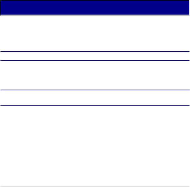
Rack Mounting
You can mount the console server in a rack or cabinet, or place it on a desktop or other flat surface. For rack or cabinet mounting, two mounting brackets are supplied.
To rack mount a console server:
8Avocent® ACS 6000 Advanced Console Server
1.Install the brackets at the front or back edges of the console server with the screws provided with the mounting kit.
2.Mount the console server in a secure position.
Bracket Connections for Front Mount Configuration
Connecting the Hardware
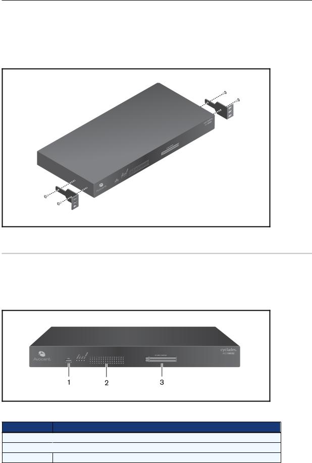
Console server connectors
The following figure shows the connectors on the front of the ACS 6000 console server.
Front of the Console Server (ACS 6032 Console Server Shown)
Connectors on the Console Server Front
Number Description
1 USB connector
2 LEDs
LEDs
3PC card slots (not available on all models)
Installation 9
LEDs on the Console Server Front
Label |
Description |
|
|
|
|
|
• Blue Blinks - During unit boot |
|
PWR/CPU |
• Solid - During operation |
|
|
• Off - Power is off |
|
|
|
|
|
• Amber - Link at 10BaseT speed |
|
ETH 0/ETH 1 |
• Yellow - Link at 100BaseT speed |
|
• Green - Link at 1000BaseT speed |
||
|
||
|
• Off - No link/cable disconnected/Ethernet fault |
|
|
|
|
|
Dual LED: Yellow on top, green on bottom |
|
AUX/MODEM |
• Yellow - DTR/DCD activity |
|
• Green - TXD and RXD activity |
||
|
||
|
• Off - No activity |
|
|
|
|
|
Green |
|
[One LED for each serial port] |
• Blinks - Ready, with activity |
|
• Solid - Ready |
||
|
• Off - Not ready |
|
|
|
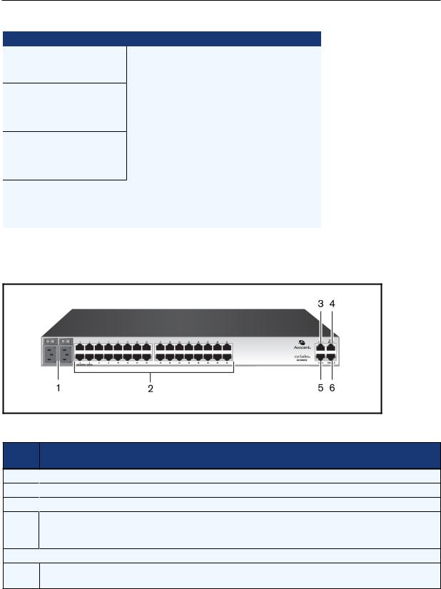
The following figure shows the rear connectors on the console server.
Rear of the Console Server (ACS 6032 Console Server Shown)
Connectors on the Console Server Rear
Number Description
1 Power supplies (dual AC shown).
2 Serial ports (32 ports shown). Models come with 4, 8, 16, 32 or 48 serial ports.
3 ETH 1 10/100M/1G Ethernet port. Can be connected to a second network or used for failover.
AUX/Modem port. If an optional internal modem is ordered, this port is defined as a V.92 modem at
4the factory; otherwise, the port is factory-defined as RS-232 with an RJ-45 ACS console server pinout and can be used to connect either an external modem or a power device.
5 ETH0 10/100M/1G Ethernet port for remote IP access.
6
Console port. Allows for local administration and access to connected devices through a terminal or a computer with a terminal emulator.
10 Avocent® ACS 6000 Advanced Console Server
Connecting device consoles or modems to serial ports
Use CAT 5 or greater cables and DB-9 or DB-25 console adaptors as needed to connect target device consoles or modems to the serial ports on the console server.
The console server supports the Cisco® serial port pinout configuration, which is disabled by default. If a Cisco cable is connected to a port, an administrator must enable the Cisco pinout for the port. An administrator can select Expert - PortsSerialPorts- (SetCAS or SetPower) - Physical to open the PhysicalSettingsscreen, then check EnableCiscoRJPin-Out.
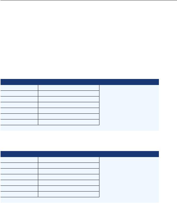
The following tables showserial port pinout information.
ACS Console Server Serial Port Pinout
Pin No. |
Signal Name |
Input/Output |
|
|
|
1 |
RTS |
OUT |
|
|
|
2 |
DTR |
OUT |
|
|
|
3 |
TxD |
OUT |
|
|
|
4 |
GND |
N/A |
|
|
|
5 |
CTS |
IN |
|
|
|
6 |
RxD |
IN |
|
|
|
7 |
DCD/DSR |
IN |
|
|
|
8 |
Not Used |
N/A |
|
|
|
Cisco Serial Port Pinout
Pin No. |
Signal Name |
Input/Output |
|
|
|
1 |
CTS |
IN |
|
|
|
2 |
DCD/DSR |
IN |
|
|
|
3 |
RxD |
IN |
|
|
|
4 |
GND |
N/A |
|
|
|
5 |
Not Used |
N/A |
|
|
|
6 |
TxD |
OUT |
|
|
|
7 |
DTR |
OUT |
|
|
|
8 |
RTS |
OUT |
|
|
|
To connect devices, modems and PDUs to serial ports:
Make sure the crossover cable used to connect a device has the same pinout type that is configured in the software for the port (either Cyclades or Cisco).
1.Make sure the devices to be connected are turned off.
2.Use CAT 5 or greater crossover cables to connect the devices to the console server, using an adaptor, if necessary.

Installation 11
3.To connect modems, use straight-through CAT 5 or greater cables, with an appropriate connector or adaptor (USB, DB-9 or DB-25) for the modem.
NOTE: To comply with EMC requirements, use shielded cables for all port connections.
WARNING: Do not turn on the power on the connected devices until after the console server is turned on.
To daisy chain PDUs to a console server:
This procedure assumes that you have one PDUconnected to a serial port on a console server.
NOTE: Daisy chaining is not possible with SPC PDUs. ServerTech PDUs will allow only one level (Master
and Slave) of daisy chaining.
1.Connect one end of a UTP cable with RJ-45 connectors to the OUT port of the connected PDU.
2.Connect the other end of the cable to the INport of the chained PDU. Repeat both steps until you have connected the desired number of PDUs.
NOTE: For performance reasons, Avocent recommends connecting no more than 128 outlets per serial
port.
Turning On the Console Server
The console server is supplied with single or dual ACor DCpower supplies.
WARNING: Always execute the shutdown command through the web manager, CLI or DSView software under the Overview/Tools node before turning the console server off, then on again. This will ensure the reset doesn't occur while the file system in Flash is being accessed, and it helps avoiding Flash memory corruptions.
AC power
To turn on a console server with AC power:
1.Make sure the console server is turned off.
2.Plug the power cable into the console server and into a power source.
3.Turn the console server on.
4.Turn on the power switches of the connected devices.
12 Avocent® ACS 6000 Advanced Console Server
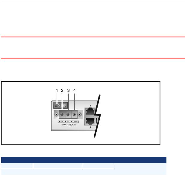
DC power
DCpower is connected to DC-powered console servers by way of three wires: Return (RTN),
Ground (GND) and -48 VDC.
WARNING: It is critical that the power source supports the DC power requirements of your console server. Make sure that your power source is the correct type and that your DC power cables are in good condition before proceeding. Failure to do so could result in personal injury or damage to the equipment.
The following diagram shows the connector configuration for DCpower.
DC Power Connection Terminal Block
DC Power Connection Details
Number |
Description |
Number |
Description |
|
|
|
|
1 |
Power switch |
3 |
GND (Ground) |
|
|
|
|
2 |
RTN (Return) |
4 |
-48 VDC |
|
|
|
|
To turn on a console server with DC power:
1.Make sure the console server is turned off.
2.Make sure DCpower cables are not connected to a power source.
3.Remove the protective cover from the DCpower block by sliding it to the left or right.
4.Loosen all three DCpower connection terminal screws.
5.Connect your return lead to the RTNterminal, your ground lead to the GNDterminal and your -48 VDClead to the -48 VDCterminal and tighten the screws.
6.Slide the protective cover back into place over the DCterminal block.
7.If your console server has dual-input DCterminals, repeat steps 3-6 for the second terminal.
8.Connect the DCpower cables to the DCpower source and turn on the DCpower source.
9.Turn on the console server.

Installation 13
10. Turn on the power switches of the connected devices.
Configuring a Console Server
A console server may be configured at the appliance level through the command line interface accessed through the CONSOLE or Ethernet port. All terminal commands are accessed through a terminal or PCrunning terminal emulation software.
NOTE: To configure using DSView software, see the DSView Software Installer/User Guide. To configure using the console server’s web manager, see Chapter 3. To configure using Telnet or SSH, see the ACS 6000 Command Reference Guide.
To connect a terminal to the console server:
1.Using a null modem cable, connect a terminal or a PCthat is running terminal emulation software (such as HyperTerminal®) to the CONSOLE port on the back panel of the console server. An RJ-45 to DB9 (female) cross adaptor is provided.
The terminal settings are 9600 bits per second (bps), 8 bits, 1 stop bit, no parity and no flow control.
2.Turn on the console server. When the console server completes initialization, the terminal will display the login banner plus the login prompt.
Using Telnet or SSH
An authorized user can use a Telnet or SSHclient to make a connection directly to the console of a device if all of the following are true:
The Telnet or SSH:
•protocol is enabled in the selected security profile
•protocol is configured for the port
•client is available, and it is enabled on the computer from which the connection is made
To use Telnet to connect to a device through a serial port:
For this procedure, you need the username configured to access the serial port, the port name (for example, 14-35-60-p-1), device name (for example, ttyS1), TCP port alias (for example, 7001) or IP port alias (for example, 100.0.0.100) and the hostname of the console server or its IP address.
To use a Telnet client, enter the information in the dialog boxes of the client.
-or-
To use Telnet in a shell, enter the following command:

14 Avocent® ACS 6000 Advanced Console Server
# telnet [hostname | IP_address]
login: username:[portname | device_name]
-or-
# telnet [hostname| IP_address] TCP_Port_Alias
login: username
-or-
# telnet IP_Port_Alias
login: username
To close a Telnet session:
Enter the Telnet hotkey defined for the client. The default is Ctrl ] + q to quit, or enter the text session hotkey for the CLI prompt and then enter quit.
To use SSH to connect to a device through a serial port:
For this procedure, you need the username configured to access the serial port, the port name (for example, 14-35-60-p-1), TCP port alias (for example, 7001), device name (for example, ttyS1), and the hostname of the console server, IP address or IP Port alias (for example, 100.0.0.100).
To use an SSHclient, enter the information in the dialog boxes of the client.
-or-
To use SSHin a shell, enter the following command:
ssh -l username:port_name [hostname | IP_address]
-or-
ssh -l username:device_name [hostname | IP_address]
-or-
ssh -l username:TCP_Port_Alias [hostname | IP_address]
-or-
ssh -l username IP_Port_Alias
To close an SSH session:
Installation 15
At the beginning of a line, enter the hotkey defined for the SSHclient followed by a period. The default is ~. Or, enter the text session hotkey for the CLI prompt and then enter quit.

Installation 16
Accessing the Console Server via the Web Manager
Once you’ve connected your ACS 6000 console server to a network, you can access the console server with its web manager. The web manager provides direct access to the console server via a graphical user interface instead of a command-based interface.
NOTE: For instructions on accessing the console server via the CLI or DSView software see the Cyclades
ACS 6000 Command Reference Guide or the DSView Software Installer/User Guide.
Web Manager Overview for Administrators
NOTE: For an overview of the web manager for regular users, see WebManagerOverview forRegular
Users on page 70.
To log into the web manager:
1.Open a web browser and enter the console server IP address in the address field.
2.Log in as either admin with the password avocent or as root with the password linux.
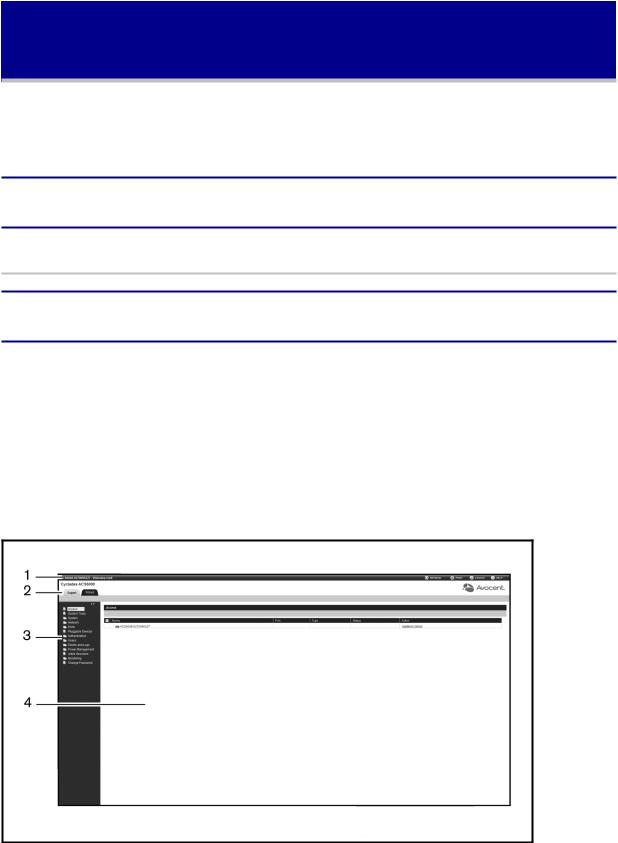
Figure 3.1 shows a typical web manager screen for an administrator and descriptions followin
Table 3.1.
Administrator Web Manager Screen
18 Avocent® ACS 6000 Advanced Console Server
Web Manager Screen Areas
Number Description
1 |
Top option bar. The name of the appliance and of the logged in user appear on the left side. |
|
Refresh, Print, Logout and Help buttons appear on the right. |
||
|
||
|
|
|
2 |
Tab bar. Displays whether the admin is in Expert or Wizard mode. |
|
|
|
|
3 |
Side navigation bar. Menu options for configuration, viewing of system information and access to |
|
devices. The options change based on user rights. |
||
|
||
|
|
|
4 |
Content area. Contents change based on the options selected in the side navigation bar. |
|
|
|
Wizard Mode
The Wizard mode is designed to simplify the setup and configuration process by guiding an administrator through the configuration steps. An administrator can configure all ports in the CAS Profile and set the Security Profile, Network and Users Settings using the Wizard.
By default, the first time an administrator accesses the console server through the web manager, the Wizard will be displayed. Subsequent log-ins will open in Expert mode, and once the console server has been configured, Expert mode becomes the default mode. An administrator can toggle between Expert and Wizard modes by clicking the tab bar on the web manager administrator screen.
Figure 3.2 shows a typical screen when an administrator is in Wizard mode.
Wizard Screen
The following procedures describe howto configure the console server from the Wizard.
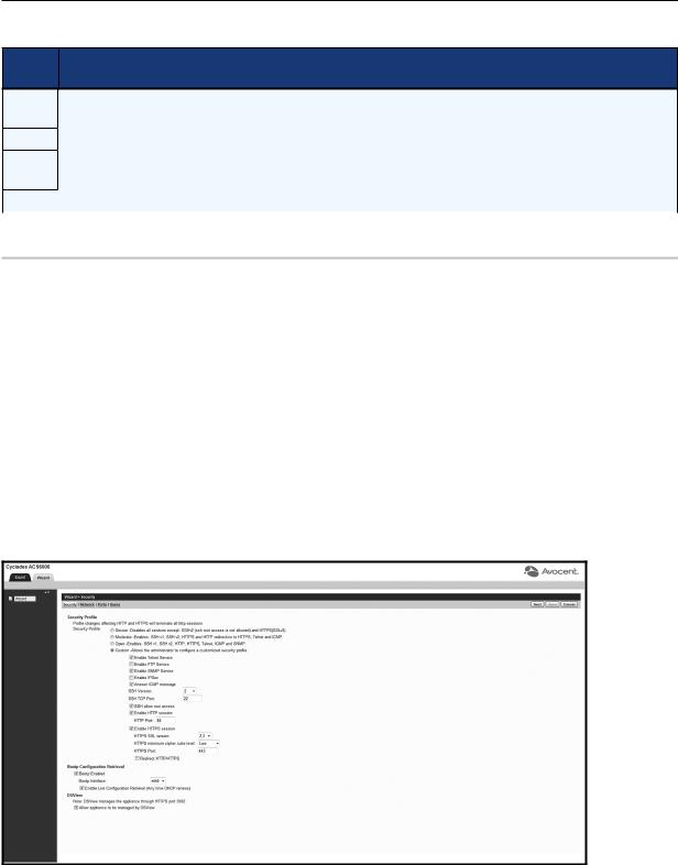
To configure security parameters and select a Security Profile:
1. Select the Securitylink in the content area.

Accessing the Console Server via the Web Manager 19
2.Select the desired Security Profile. If using a Custom Security Profile, click the checkboxes and enter values as needed to configure the services, SSHand HTTP and HTTPS options to conform with your site security policy.
3.Under the Bootp Configuration Retrieval heading, uncheck the box(es) to disable Bootp configuration retrieval and/or live configuration retrieval.
4.If you are not using DSViewsoftware to manage the appliance, uncheck the Allow Appliance tobeManagedbyDSView box.
5.Click Next to configure the Network or click the Network, Portsor Userslink to open the appropriate screen.
To configure network parameters:
1.Select the Networklink in the content area.
2.Enter the Hostname, Primary DNS and Domain in the appropriate fields.
3.Select the IPv4 or IPv6 method for the ETH0 interface. If using Static, enter the Address, Mask and Gateway in the appropriate fields.
4.Enable or disable IPv6 support.
5.Click Next to configure ports or click on the Security, Portsor Userslink to open the appropriate screen.
To configure Ports:
1.Select the Portslink in the content area.
2.Check the box(es) to enable all ports and/or to enable Cisco RJ45 Pin-Out to change the pinout when a Cisco cable is connected.
3.Use the appropriate drop-down menus to select the values for Speed, Parity, Data Bits, Stop Bits, FlowControl, Protocol, Authentication Type and Data Buffering Status.
4.Select the Data Buffering Type. If using NFS, enter the NFS Server and NFS Path information in the appropriate fields.
5.Click Next to configure users or click on the Network, Securityor Userslink to open the appropriate screen.
To configure users and change the default user passwords:
WARNING: For security reasons, it is recommended you change the default password for both root and
admin users immediately.
1.Select the Userslink in the content area.
2.Click a username (admin or root) and enter the newpassword in the Password and Confirm Password fields.

20 Avocent® ACS 6000 Advanced Console Server
-or-
Click Add to add a user. Enter the newusername and password in the appropriate fields.
3.(Optional) To force the user to change the default password, select the User mustchange passwordatnextlogin checkbox.
4.Assign the user to one or more groups.
5.(Optional) Configure account expiration and password expiration.
6.Click Next.
7.Repeat steps 3-7 as needed to configure newuser accounts and assign them to default groups.
NOTE: By default, all configured users can access all enabled ports. Additional configuration is needed if
your site security policy requires you to restrict user access to ports.
8. Click Save, then click Finish.
Expert Mode
The following tabs are available in the side navigation bar of the web manager when an administrator is in Expert mode.
Access
Click Accessto viewall the devices connected to the console server.
To view and connect to devices using the web manager:
1.Select Accessin the side navigation bar. The content area displays the name of the console server and a list of names or aliases for all installed and configured devices the user is authorized to access.
2.Select SerialViewer from the Action column. A Java® applet viewer appears. In a gray area at the top of the viewer, the Connectedto message shows the IP address of the console server followed by the default port number or alias.
3.Log in if prompted.
The following table describes the available buttons in the Java applet.
Java Applet Buttons for Connecting to the
Button |
Purpose |
SendBreak |
To send a break to the terminal |
Accessing the Console Server via the Web Manager 21
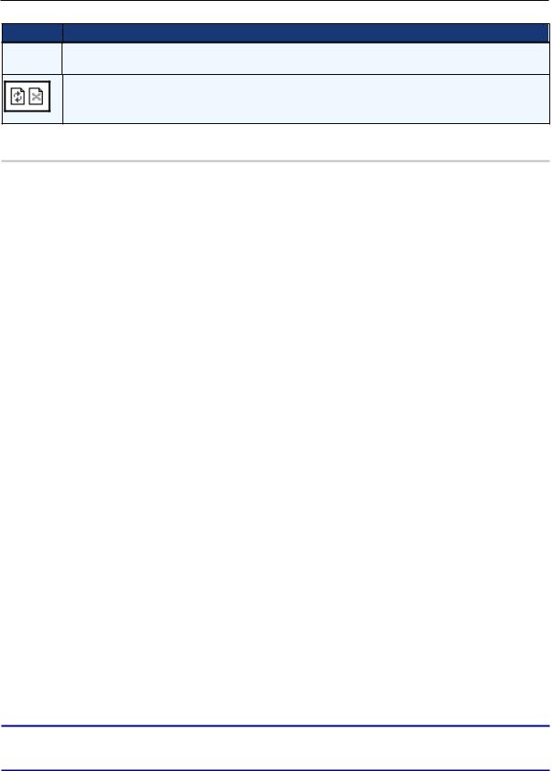
Button Purpose
Disconnect To disconnect from the Java applet
Select the left icon to reconnect to the server or device; or select the right icon to end the session and disconnect from the Java applet
System Tools
Click SystemToolsto display icons which can be clicked to reboot or shut down the console server, upgrade the console server’s firmware, save or restore its configuration or open a terminal session with the console server.
To upgrade a console server's firmware:
1.From http://www.avocent.com, browse to the product updates section and find the firmware for your console server.
2.Save the newfirmware to an FTP server or to your desktop.
3.From the sidebar of the console server's web manager, click SystemTools, then click
UpgradeFirmware.
4.Download the file from an FTP server by selecting FTP server.
a.In the FTP site field, enter the address of the FTP server where you saved the firmware.
b.Enter the username and password for the FTP server in the appropriate fields.
c.Enter the file directory where the firmware is saved and the filename for the firmware in the appropriate fields.
-or-
Download the file from your desktop by selecting My Computer.
a.Type the filename for the newfirmware or click Browse to open a windowto browse to the file.
5.Click Download. The console server will download the firmware from the specified site and will display a message when the download is complete.
6.Click Install.
7.Once the newfirmware is installed, reboot the console server.
NOTE: If the page after installation displays empty or blank values, there was not enough memory to upgrade the firmware. Reboot the console server and upgrade the firmware again.

22 Avocent® ACS 6000 Advanced Console Server
System
Click System to display information about the console server and allowan administrator to configure the console server’s system parameters. The following tabs are listed under System in the side navigation bar.
Security
Security Profile
A Security Profile determines which network services are enabled on the console server.
During initial configuration, the console server administrator must configure security parameters to conform with the site security policy. The following security features can be configured either in the web manager, CLI or the DSViewsoftware:
•Configure the session idle time-out
•Enable or disable RPC
•Ability to configure access for all users, or allowthe configuration of group authorizations to restrict access
•Select a Security Profile, which defines:
•Enabled services (FTP, ICMP, IPSec and Telnet)
•SSHand HTTP/HTTPS access
•Enable or disable Bootp Configuration retrieval
The administrator can select either a preconfigured Security Profile or create a custom profile.
All the services and the SSHand HTTP/HTTPS configuration options that are enabled and disabled for each Security Profile are shown in the Wizard - Security and the System - Security - Security Profile pages.
To configure a Security Profile:
1.Select System - SecuritySecurityProfile.
2.In the Idle Timeout field, enter the number of minutes before the console server times out open sessions.
NOTE: This value applies to any user session to the appliance via HTTP, HTTPS, SSH, Telnet or CONSOLE port. It will not overwrite the value configured for the user's authorization group. The new idle time-out will be applied to new sessions only.
3. Under the Enabled Services section, enable or disable the RCP checkbox.
Loading...