


79U-002
Emerson 79U-002, 79E, 79U-003, 79U-006, 79U-036 Operating And Maintenance Instructions Manual
...
KEYSTONE FIGURE 79 PNEUMATIC ACTUATOR
OPERATING AND MAINTENANCE INSTRUCTIONS
Operating and Maintenance Instructions for: Figure 79 Pneumatic Actuators (U/E options)
4. If pipelines are hydraulically tested, then
the lines should be “blown down” with high
pressure air to clear all water, prior to
connecting lines to the actuator.
5. Where pipe fitting sealants are used, they
should be applied to the male threads only.
When applied to female threads, excess
compound can be transmitted into the
actuator control lines.
Double Acting Actuator
6. Where a system is dependent on Air Filter
Equipment, the air filters should be situated
in positions that allow easy access to
maintain and/or drain.
7. Where pneumatic valve positioners, or
pneumatic controllers are fitted to valve
actuator assemblies, oil mist lubricated air
should not be used unless the manufacturer
states specifically that the controllers are
compatible with lubricated air.
Single Acting Actuator
Introduction
The Keystone Figure 79 Pneumatic Actuator
range is available in three mounting options, as
follows: 79U - Keystone Mounting Standard
79E - ISO5211
General Pneumatic Systems Recommendations
All Keystone Pneumatic Actuators are factory
lubricated with Molyrace LT grease and, unless
the operating environment is extremely poor,
do not require re-lubrication. To maintain
maximum efficiency with this, or other
pneumatic actuators or pressure vessels,
we advise that the following basic system
recommendations are followed:
1. Where air pipelines are subjected to
extremes of temperature, the system should
be fitted with air drying equipment.
2. Air control lines should be run to a
‘Recommended Piping Practice’ and should
not have “exaggerated” loops which may
trap condensate.
3. All pipe ends should be thoroughly cleaned
and deburred after cutting to ensure that
the pipeline is clear of cuttings.
Note: Figure 79 Actuators are rated for air
pressure in the range 40psig (2.75barg)
to 120psig (8.3barg) and can withstand a
maximum of 150psig (10barg).
Construction
Figure 79 actuators are available in a range
of sizes producing up to 27624lb in/ 3121Nm
output torque and are designed to be mounted
to quarter turn valves either directly or using
the correct mounting brackets/adaptors and
sizing procedures.
All models are of the opposed piston type. Each
piston incorporates a wide toothed rack which
engages a one piece drive shaft. The drive
shaft is sealbond (TM) treated for maximum
protection. The actuator body is of extruded
aluminium and is fitted with “Engineered
polymer” bearings at the drive shaft locations.
Bearing and piston seals are dynamic ‘O’-ring
type. The actuator drive is by means of a double
keyed female shaft (79U/E). A comprehensive
range of double “D” adaptors is available for
fitting to both the top and bottom of the output
shaft for accessories (top) and valve stems
(bottom).
Emerson.com/FinalControl VCIOM-01733-EN 17/04
© 2017 Emerson. All Rights Reserved.

KEYSTONE FIGURE 79 PNEUMATIC ACTUATOR
OPERATING AND MAINTENANCE INSTRUCTIONS
STANDARD INSTALLATION - DOUBLE &
SINGLE ACTING UNITS
These instructions assume that the actuators
are installed with the cylinder axis parallel to
the axis of the valve bore (In Line).
Single acting actuators are supplied as
FAIL-CLOSE units as standard.
Reverse acting FAIL-OPEN must be specified at
the time of order.
The actuator is mounted as follows:
1. Ensure that the valve and actuator are both
in the following positions:
Double Acting units - fully closed
Single Acting units - air fail mode
(normallyclosed)
2. Check that the actuator mounting studs are
tightly secured in the actuator housing.
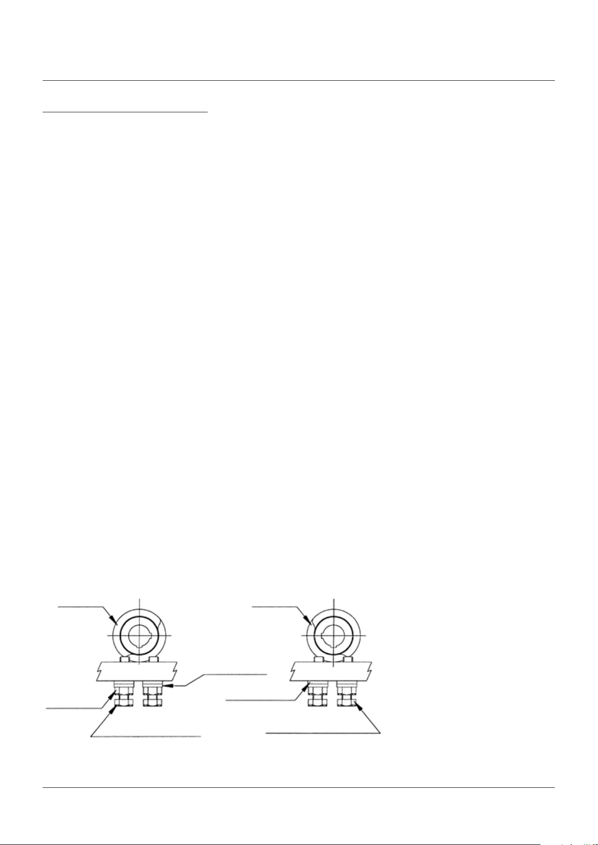
3. Install the correct adaptor, if required, into
the actuator (fig. 1 - direct mounting) or
install the correct coupling and bracketry,
if required, to the valve (fig. 2 - bracket
mounted option).
See Notes 1 & 2
4. Mount the actuator onto the valve flange or
the bracket and secure using a lockwasher
and nut on each mounting stud.
5. Before installing the valve/actuator
assembly in a piping system, the disc travel
should be verified.
6. When installing the valve/actuator assembly
into pipeline, ensure that the specific
instructions relating to the valve installation
are followed. For valves which need to be
fitted with the valve in a position other than
fully closed, it may be necessary to fit the
valve into the pipeline prior to mounting the
actuator to the valve. Rubber lined butterfly
valves are an example of this.
7. For valves which need to be installed in the
pipeline prior to fitting the actuator, ensure
that the valve is operated into its failsafe
position before mounting the actuator onto
the valve.
3. Refit actuator to the top of the valve. (note:on models 036/065/090 adaptors may not be
required to be fitted ie directly mounted, in
this case simply use the previously unused
keyway.)
NOTES
1. The adaptor should be lightly tapped or pressed
into the actuator.
2. The coupling should be lightly tapped or pressed
onto the valve stem.
Excessive force should not be used (the use of a
lubricant such as Coppaslip is recommended).
FIGURE 1
Lockwasher
FIGURE 2
Lockwasher
Nut
Bolt
Pneumatic
actuator
Valve
Pneumatic
actuator
Adaptor
ifrequired
Adaptor
ifrequired
Stud
Nut
Stud
Coupling
if required
NON STANDARD INSTALLATION - DOUBLE &
SINGLE ACTING UNITS
In circumstances where the actuator is
required to be installed in the transverse
position i.e. at right angles to the valve bore
(Across Line), the actuator must be rotated
through 90°.
This is achieved in the following manner:
1. Remove the actuator from the valve or the
bracket by unscrewing the 4 fixing nuts and
withdraw it vertically from the valve.
2. 79U/E Models - remove the double ‘D’
adaptor located in the bore at the bottom of
the actuator and re-fit, locating in previously
unused keyway of shaft.
Ball
valve
Bracket
if required
2

KEYSTONE FIGURE 79 PNEUMATIC ACTUATOR
OPERATING AND MAINTENANCE INSTRUCTIONS
DISASSEMBLY - DOUBLE ACTING UNITS
Note: Please refer to the relevant exploded
views further on.
CAUTION
Remove all air pressure and observe normal
safety precautions including the use of eye
protection.
1. Pull off the indicator cap (item 17) from
the top of the actuator. If this cap is too
tight, light pressure may be applied to the
underside via a short length of round bar
or a similar blunt ended tool, inserted from
the bottom end of the actuator shaft. (Note:
levering with a screwdriver is considered
to be a potentially dangerous practice and
should be avoided.)
`The position relative to the shaft should
be noted to ensure correct position for
assembly.
2. Remove both travel stop bolts, if fitted
(items 19 to 22, see page 10 for all items)
3.
Loosen endcap fixing screws evenly (item 15)
4. Remove endcaps (item 3)
5. Rotate output shaft (item 5) in a anticlockwise direction to drive pistons apart,
and remove pistons (item 2) complete with
backing pads/rings - if fitted.
6. Remove circlip (item 12) from bottom bore
of actuator.
7. Tap shaft downward and remove. Take care
to protect the actuator bore from possible
damage from the pinion gear teeth.
8. Remove top bearing (item 9) from the
actuator body (the bottom bearing
(item 6) will have been removed along with
the pinion shaft).
DISASSEMBLY - SINGLE ACTING UNITS
Note: Please refer to the relevant exploded
views further on.
CAUTION
Remove all air pressure and observe normal
safety precautions including the use of eye
protection. Always ensure that spring return
actuators are in fail safe position before
attempting any maintenance. Pay particular
attention to this requirement when manual
operators are fitted.
For safety reasons DONOT ‘Air Assist’ Single
Acting Pneumatic actuators.
1. Pull off the indicator cap (item 17) from
the top of the actuator. If this cap is too
tight, light pressure may be applied to the
underside via a short length of round bar
or a similar blunt ended tool, inserted from
the bottom end of the actuator shaft. (Note:
levering with a screwdriver is considered
to be a potentially dangerous practice and
should be avoided.)
The position relative to the shaft should
be noted to ensure correct position for
assembly.
2. Remove both travel stop bolts, if fitted
(items 19 to 22, see page 11 for all items).
3. Loosen endcap/spring return housing fixing
screws (item 15) evenly until the spring load
is relaxed (3 - 5 mm).
Warning: If, after loosening the screws
by 5mm there is still compression on the
spring pack, re-tighten the endcap screws
and return the unit to the factory for service.
4. Remove endcap/spring housing assemblies.
Warning: Under no circumstances should
the spring retaining bolt be loosened or
adjusted without first consulting the factory.
5. Rotate output shaft (item 5) in an anticlockwise direction to drive pistons apart
and remove pistons (item 2) complete with
backing pads/rings - if fitted.
6. Remove circlip (item 12) from bottom bore
of actuator.
7. Tap shaft downward and remove. Take
care to protect actuator bore from possible
damage from the pinion gear teeth.
8. Remove top bearing (item 9) from the
actuator body (the bottom bearing (item
6) will have been removed along with the
pinion shaft).
3
KEYSTONE FIGURE 79 PNEUMATIC ACTUATOR
OPERATING AND MAINTENANCE INSTRUCTIONS
ASSEMBLY - DOUBLE ACTING UNITS
Note: Please refer to the relevant exploded
views further on.
Liberally grease actuator bore, pistons and
pinion assembly with Molyrace LT lubricant.
1. Coat all ‘O’-ring seals with Molyrace LT
lubricant.
2. Output shaft assembly:-
a) Fit the top bearing assembly (item 9) into
the top bore of the actuator body (item 1)
with the outer o-ring uppermost.
b) Fit the bottom bearing assembly (item 6)
on to the bottom of the pinion shaft (item
5) with internal o-ring uppermost.
3. Insert pinion shaft assembly from underside
of the actuator as shown in fig. 4.
4. Fit internal circlip (item 12) to bottom recess
of body to locate the shaft assembly.
5.
Fit ‘O’-ring seals (item 13) on pistons (item 2).
6. Orientate output shaft at 45° ± 2°.
7. Insert pistons (item 2) complete with
backing pads(1) (item 18) and backing rings
(5), with piston legs on left side of bore
(when viewed from the o-ring end of the
piston), until racks engages with pinion and
then push fully inward, the actuator is now
in the fully closed position.
* If no travel stops are fitted proceed to
instruction 12.
8. Turn the pinion shaft anti-clockwise
approximately 5° until it is orientated in line
with the major axis of the actuator body. The
shaft is now in the closed position.
9. Insert CLOSE travel stop bolt (item 19/20)
together with sealing nut or lock nut (2)(3),
flat washer (2)(3) and sealing washer (2)(3)
until the bolt hits the travel stop cam. Tighten
the lock nut.
10. Turn the pinion shaft anti-clockwise through
90° to bring it in line with the center line of
the actuator bore, the actuator is now in the
open position.
11. Insert Open travel stop bolt (item 19/20)
(together with sealing nut or lock nut (2)
(3), flat washer (2)(3) and sealing washer (2)
(3)) until the bolt hits the travel stop cam.
Tighten the lock nut.
12.
Fit ‘O’-ring seals (item 14) to endcaps (item 3)
using a light smear of grease.
13. Fit endcaps to body and alternately tighten
the endcap screws (item 15) until secure
(see recommended torque table).
14. Fit position indicator to top of actuator.
15. Operate the actuator to OPEN & CLOSE
positions using compressed air and note the
actual positions. If the required travel is not
achieved refer to page 12.
NOTES
1 Backing pads are not required on 002/003 models
which have nylon pistons.
2 Lock nuts, flat washers and sealing washers are
only fitted to models 065-180.
3 On models 003/036 the lock nut & sealing nut are
one item.
4 Gear shim is required on models 006 and 012 only.
5 Backing rings and pads are only fitted to models
065/090/180.
Note: Backing pads and rings need only a smear of
grease on the undersides before fitting to pistons.
FIGURE 3
Camshaft
Locking nut
(Models 065 to 180)
Open position
Actuator body
Open adjustment bolt
Camshaft
Flat washer
(Models 065 to 180)
Sealing washer
(Models 065 to 180)
Viewed from top of actuator
Close position
Actuator body
Close adjustment bolt
4
 Loading...