


3D39695G02
Emerson 3D39695G02, 3D39695G05, 3D39695G03, 3D39695G04, 3D39695G06 Instruction Manual
...
Instruction Manual
IM-106-400 IMPS, Rev. 2.0
February 2009
IMPS 4000
Intelligent Multiprobe
Test Gas Sequencer
http://www.raihome.com


HIGHLIGHTS OF CHANGES
Effective February 28, 2009 - Rev. 2.0
Page Summary
General Reformatted entire manual in accordance with Emerson Process Management style and
format requirements. Changed all general references to Oxymitter to read oxygen
transmitter. Changed specific references to Oxymitter 4000 to include X-STREAM O
Transmitter. Revised illustrations to meet Emerson Process Management format
requirements and to show updated Rosemount Analytical product logo where applicable.
Cover Updated photo, revision number and release date.
Page i and ii Added Essential Instructions section with Technical Support Hotline information.
1-1 Revised text of NOTE.
1-4 Revised Figure 1-3 to include electrical and pneumatic diagram connections from IMPS
to X-STREAM probe housing and Xi unit.
2-4 Revised Electrical Connections discussion to include separate steps for Oxymitter and
X-STREAM. Changed all OXT terminal indicators to read XMTR.
2-5 Revised Figure 2-3 to include X-STREAM Xi unit connection and setup data.
3-6 and 3-7 Revised Automatic Calibration instructions to include expanded autocalibration setup
details for Oxymitter and new setup details for X-STREAM.
3-7 Added Xi Keypad paragraph to Semi-Automatic Calibration instructions.
A-1 Added new Appendix A , Safety Data.
B-1 Added new Appendix B, Return of Material.
I-1 Added new Index.
Back Cover Updated company addresses.
2


Instruction Manual
IM-106-880, Rev 2.0
February 2009
IMPS 4000
Table of Contents
Essential Instructions. . . . . . . . . . . . . . . . . . . . . . . . . . . . . . . . . . . . . . . . i
Preface . . . . . . . . . . . . . . . . . . . . . . . . . . . . . . . . . . . . . . . . . . . . . . . . . . ii
Definitions . . . . . . . . . . . . . . . . . . . . . . . . . . . . . . . . . . . . . . . . . . . . . . . . ii
Symbols. . . . . . . . . . . . . . . . . . . . . . . . . . . . . . . . . . . . . . . . . . . . . . . . . . ii
Technical Support Hotline . . . . . . . . . . . . . . . . . . . . . . . . . . . . . . . . . . . . ii
SECTION 1
Description and
Specifications
SECTION 2
Installation
SECTION 3
Operation
Introduction . . . . . . . . . . . . . . . . . . . . . . . . . . . . . . . . . . . . . . . . . . . . . 1-1
Component Checklist. . . . . . . . . . . . . . . . . . . . . . . . . . . . . . . . . . . . . . 1-2
System Overview. . . . . . . . . . . . . . . . . . . . . . . . . . . . . . . . . . . . . . . . . 1-2
Physical Description . . . . . . . . . . . . . . . . . . . . . . . . . . . . . . . . . . . . 1-2
Theory of Operation. . . . . . . . . . . . . . . . . . . . . . . . . . . . . . . . . . . . . . . 1-4
Z-Purge Option . . . . . . . . . . . . . . . . . . . . . . . . . . . . . . . . . . . . . . . . . . 1-5
Specifications. . . . . . . . . . . . . . . . . . . . . . . . . . . . . . . . . . . . . . . . . . . . 1-5
Overview . . . . . . . . . . . . . . . . . . . . . . . . . . . . . . . . . . . . . . . . . . . . . . . 2-1
Mechanical Installation . . . . . . . . . . . . . . . . . . . . . . . . . . . . . . . . . . . . 2-1
Gas Connections . . . . . . . . . . . . . . . . . . . . . . . . . . . . . . . . . . . . . . . . . 2-3
Electrical Connections . . . . . . . . . . . . . . . . . . . . . . . . . . . . . . . . . . . . . 2-3
Switch Settings . . . . . . . . . . . . . . . . . . . . . . . . . . . . . . . . . . . . . . . . . . 2-5
Overview . . . . . . . . . . . . . . . . . . . . . . . . . . . . . . . . . . . . . . . . . . . . . . . 3-1
Calibration Requirements . . . . . . . . . . . . . . . . . . . . . . . . . . . . . . . . . . 3-1
Operator Interface Description. . . . . . . . . . . . . . . . . . . . . . . . . . . . . . 3-2
Membrane Keypad . . . . . . . . . . . . . . . . . . . . . . . . . . . . . . . . . . . . . 3-3
LCD Display . . . . . . . . . . . . . . . . . . . . . . . . . . . . . . . . . . . . . . . . . . 3-3
Using The Operator Interface . . . . . . . . . . . . . . . . . . . . . . . . . . . . . . 3-5
Selecting a Parameter . . . . . . . . . . . . . . . . . . . . . . . . . . . . . . . . . . 3-5
Changing a Typical Parameter . . . . . . . . . . . . . . . . . . . . . . . . . . . . 3-5
Test Gas Flow Setup . . . . . . . . . . . . . . . . . . . . . . . . . . . . . . . . . . . . . . 3-6
Automatic Calibration. . . . . . . . . . . . . . . . . . . . . . . . . . . . . . . . . . . . . . 3-6
Semi-Automatic Calibration . . . . . . . . . . . . . . . . . . . . . . . . . . . . . . . . 3-7
SECTION 4
Troubleshooting
http://www..raihome.com
Overview . . . . . . . . . . . . . . . . . . . . . . . . . . . . . . . . . . . . . . . . . . . . . . . 4-1
Troubleshooting. . . . . . . . . . . . . . . . . . . . . . . . . . . . . . . . . . . . . . . . . . 4-1
Calibration Troubleshooting. . . . . . . . . . . . . . . . . . . . . . . . . . . . . . . . . 4-3
PLC I/O LED Indications . . . . . . . . . . . . . . . . . . . . . . . . . . . . . . . . . . . 4-4

IMPS 4000
Instruction Manual
IM-106-4000 IMPS, Rev 2.0
February 2009
SECTION 5
Maintenance and Service
SECTION 6
Replacement Parts
APPENDIX A
Safety Data
APPENDIX B
Return of Material
Overview . . . . . . . . . . . . . . . . . . . . . . . . . . . . . . . . . . . . . . . . . . . . . . . 5-1
Fuse Replacement. . . . . . . . . . . . . . . . . . . . . . . . . . . . . . . . . . . . . . . . 5-3
PLC Replacement . . . . . . . . . . . . . . . . . . . . . . . . . . . . . . . . . . . . . . . . 5-3
Operator Interface Replacement . . . . . . . . . . . . . . . . . . . . . . . . . . . . . 5-5
Solenoid Replacement. . . . . . . . . . . . . . . . . . . . . . . . . . . . . . . . . . . . . 5-5
Pressure Regulator Maintenance . . . . . . . . . . . . . . . . . . . . . . . . . . . 5-6
Pressure Adjustments . . . . . . . . . . . . . . . . . . . . . . . . . . . . . . . . . . 5-6
Condensation Drain . . . . . . . . . . . . . . . . . . . . . . . . . . . . . . . . . . . . 5-6
Flowmeter Adjustments . . . . . . . . . . . . . . . . . . . . . . . . . . . . . . . . . . . . 5-6
Reference Gas Flowmeter . . . . . . . . . . . . . . . . . . . . . . . . . . . . . . . 5-6
Test Gas Flowmeter . . . . . . . . . . . . . . . . . . . . . . . . . . . . . . . . . . . . 5-6
Replacement Parts List . . . . . . . . . . . . . . . . . . . . . . . . . . . . . . . . . . . . 6-1
Safety Instructions . . . . . . . . . . . . . . . . . . . . . . . . . . . . . . . . . . . . . . . . A-2
Returning Material . . . . . . . . . . . . . . . . . . . . . . . . . . . . . . . . . . . . . . . . B-1
TOC-2

Instruction Manual
IM-106-400 IMPS, Rev. 2.0
February 2009
Intelligent Mutiprobe Test Gas Sequencer
4000 IMPS
READ THIS PAGE BEFORE PROCEEDING!
ESSENTIAL
INSTRUCTIONS
Emerson Process Management designs, manufactures and tests its products
to meet many national and international standards. Because these
instruments are sophisticated technical products, you MUST properly
install, use, and maintain them to ensure they continue to operate within
their normal specifications. The following instructions MUST be adhered to
and integrated into your safety program when installing, using, and
maintaining Emerson’s Rosemount Analytical products. Failure to follow the
proper instructions may cause any one of the following situations to occur:
Loss of life; personal injury; property damage; damage to this instrument; and
warranty invalidation.
• Read all instructions
product.
• If you do not understand any of the instructions, contact your
Emerson Process Management representative for clarification.
• Follow all warnings, cautions, and instructions
supplied with the product.
• Inform and educate your personnel
operation, and maintenance of the product.
• Install your equipment as specified in the Installation Instructions
of the appropriate Instruction Manual and per applicable local and
national codes. Connect all products to the proper electrical and
pressure sources.
• To ensure proper performance, use qualified personnel
operate, update, program, and maintain the product.
• When replacement parts are required, ensure that qualified people use
replacement parts specified by Emerson Process Management.
Unauthorized parts and procedures can affect the product's
performance, place the safe operation of your process at risk, and
VOID YOUR WARRANTY. Look-alike substitutions may result in fire,
electrical hazards, or improper operation.
• Ensure that all equipment doors are closed and protective covers
are in place, except when maintenance is being performed by
qualified persons, to prevent electrical shock and personal injury.
prior to installing, operating, and servicing the
marked on and
in the proper installation,
to install,
http://www.raihome.com
The information contained in this document is subject to change without
notice.

Instruction Manual
IM-103-400A, Rev. 2.0
4000 IMPS
February 2009
PREFACE The purpose of this manual is to provide information concerning the
components, functions, installation and maintenance of the IMPS 4000
Intelligent Multiprobe Test Gas Sequencer.
DEFINITIONS The following definitions apply to WARNINGS, CAUTIONS, and NOTES
found throughout this publication.
Highlights an operation or maintenance procedure, practice, condition, statement, etc. If not
strictly observed, could result in injury, death, or long-term health hazards of personnel.
Highlights an operation or maintenance procedure, practice, condition, statement, etc. If not
strictly observed, could result in damage to or destruction of equipment, or loss of
effectiveness.
SYMBOLS
TECHNICAL SUPPORT
HOTLINE
NOTE
Highlights an essential operating procedure, condition, or statement.
:
EARTH (GROUND) TERMINAL
:
PROTECTIVE CONDUCT OR TERMINAL
:
RISK OF ELECTRICAL SHOCK
:
WARNING: REFER TO INSTRUCTION MANUAL
NOTE TO USERS
The number in the lower right corner of each illustration in this publication is a
manual illustration number. It is not a part number, and is not related to the
illustration in any technical manner.
For assistance with technical problems, please call the Customer Support
Center (CSC). The CSC is staffed 24 hours a day, 7 days a week.
Phone: 1-800-433-6076 1-440-914-1261
In addition to the CSC, you may also contact Field Watch. Field Watch
coordinates Emerson Process Management’s field service throughout the
U.S. and abroad.
Phone: 1-800-654-RSMT (1-800-654-7768)
Emerson Process Management may also be reached via the Internet through
e-mail and the World Wide Web:
e-mail: GAS.CSC@emerson.com
World Wide Web: www.raihome.com
ii

Instruction Manual
IM-106-400 IMPS, Rev. 2.0
February 2009
4000 IMPS
Section 1 Description and Specifications
Introduction . . . . . . . . . . . . . . . . . . . . . . . . . . . . . . . . . . . . . page 1-1
Component Checklist . . . . . . . . . . . . . . . . . . . . . . . . . . . . . page 1-2
System Overview . . . . . . . . . . . . . . . . . . . . . . . . . . . . . . . . page 1-2
Theory of Operation . . . . . . . . . . . . . . . . . . . . . . . . . . . . . . page 1-4
Z-Purge Option . . . . . . . . . . . . . . . . . . . . . . . . . . . . . . . . . . page 1-5
Specifications . . . . . . . . . . . . . . . . . . . . . . . . . . . . . . . . . . . page 1-5
INTRODUCTION The Rosemount Analytical IMPS 4000 Intelligent Multiprobe Test Gas
Sequencer is used with the Oxymitter 4000 or the X-STREAM Oxygen
Transmitter. The IMPS 4000 has the intelligence to provide test gas
sequencing of up to four oxygen transmitters to accommodate automatic and
semi-automatic calibration routines. Table 1-1 lists the available IMPS 4000
versions.
Table 1-1. IMPS 4000 Versions
NOTE
The IMPS 4000 Intelligent Multiprobe Test Gas Sequencer operates the same
when used with the Oxymitter 4000 or the X-STREAM O
Transmitter with
2
HART or FOUNDATION fieldbus Communications. References to the
Oxymitter 4000 or the X-STREAM O
manual also include the Oxymitter 5000 and the X-STREAM O
Transmitter throughout this instruction
2
Transmitter
2
with FOUNDATION fieldbus Communications.
Part Number Description Number of O2 Transmitters
3D39695G01 IMPS 1
3D39695G02 IMPS 2
3D39695G03 IMPS 3
3D39695G04 IMPS 4
3D39695G05 IMPS w/115 V Heater 1
3D39695G06 IMPS w/115 V Heater 2
3D39695G07 IMPS w/115 V Heater 3
3D39695G08 IMPS w/115 V Heater 4
3D39695G09 IMPS w/220 V Heater 1
3D39695G10 IMPS w/220 V Heater 2
3D39695G11 IMPS w/220 V Heater 3
3D39695G12 IMPS w/220 V Heater 4
http://www.raihome.com

4000 IMPS
Instruction Manual
IM-106-400 IMPS, Rev. 2.0
February 2009
COMPONENT
CHECKLIST
Figure 1-1. Typical System Package
A typical IMPS 4000 should contain the items shown in Figure 1-1. Record
the part number, serial number, and order number for the IMPS 4000 on the
back cover of this manual.
1. Instruction Manual
2. IMPS 4000
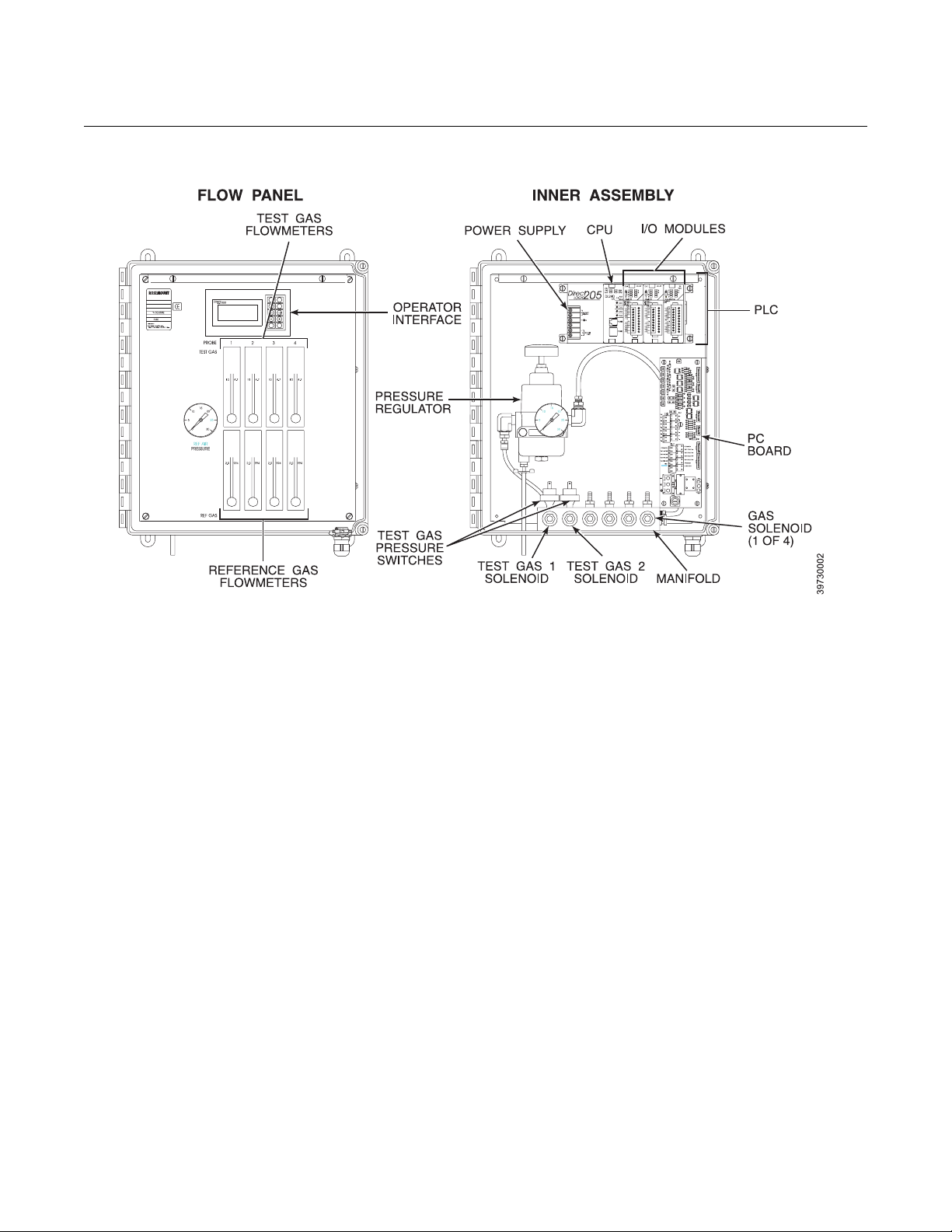
SYSTEM OVERVIEW
Physical Description The main components of the IMPS 4000 are housed in a NEMA 4X (IP56)
enclosure for use in non-hazardous areas.
The main internal components include the flow panel and the inner assembly.
Flow Panel (Figure 1-2)
The Programmable Logic Controller (PLC) operator interface and the
reference and test gas flowmeters are mounted to the flow panel.
1. The PLC operator interface allows you to set up time-sequenced
calibration routines for up to four oxygen transmitters. It also allows you
to initiate a semi-automatic calibration.
2. Four sets of test gas and reference gas flowmeters are mounted on the
flow panel. One set of flowmeters is available for each of the four
oxygen transmitters that can be attached to the IMPS 4000. The test
gas flowmeter indicates the amount of test gas sent to the oxygen
transmitter. The reference gas flowmeter indicates the amount of
reference air flowing to the oxygen transmitter.
1-2
Instruction Manual
IM-106-400 IMPS, Rev. 2.0
February 2009
Figure 1-2. IMPS Components
4000 IMPS
Inner Assembly
The inner assembly consists of the PLC, PC board, pressure regulator, gas
solenoids, test gas pressure switches, and heater.
1. The PLC consists of a power supply, Central Processing Unit (CPU),
and three I/O modules.
a. The power supply supplies the voltage and current needed to
operate the IMPS 4000.
b. The CPU controls most system operations. It contains the program
memory in which the information entered into the PLC operator
interface is stored, and it processes the I/O signals received from the
I/O modules.
c. The I/O modules are terminated on the PC board. They receive and
send signals between the PLC and PC board for communication
between the oxygen transmitter and the IMPS 4000.
2. The PC board contains all wiring connections for up to four oxygen
transmitters.
3. The pressure regulator ensures the instrument air (reference gas)
flowing to the oxygen transmitter is at a constant pressure. The
regulator also has a drain valve that drains excess moisture from the
internal gas circuit.
4. The manifold can have up to six solenoids: test gas 1 solenoid, test gas
2 solenoid, and a gas solenoid for each oxygen transmitter connected to
the IMPS 4000. The solenoids activate and deactivate to allow test gas
to flow between the IMPS 4000 and an oxygen transmitter.
1-3

Instruction Manual
IM-106-400 IMPS, Rev. 2.0
4000 IMPS
5. The pressure switches detect if the pressure of a test gas is low, which
can be caused by an empty gas bottle, a disconnected gas line, etc.
Calibration is prohibited when test gas pressure is low.
6. The heater keeps the components in the ambient temperature range to
prevent electronic malfunction.
February 2009
THEORY OF OPERATION Reference Figure 1-3. When a calibration is initiated, via the IMPS,
HART/AMS, oxygen transmitter, or remote location, the signal is sent to the
IMPS 4000 PLC. The PLC first energizes the oxygen transmitter solenoid and
then energizes the test gas 1 (high gas) solenoid. Test gas 1 flows through the
IMPS 4000 to the oxygen transmitter. The oxygen transmitter measures the
oxygen content of test gas 1 and sends a signal to the IMPS 4000 indicating
that it received test gas 1. When the IMPS 4000 receives the signal, the PLC
deenergizes the test gas 1 solenoid.
Figure 1-3. IMPS Calibration Setup
1-4

Instruction Manual
IM-106-400 IMPS, Rev. 2.0
February 2009
4000 IMPS
After a time delay that allows test gas 1 to clear the system, the PLC
energizes the test gas 2 (low gas) solenoid. Test gas 2 flows through the
IMPS 4000 to the oxygen transmitter. The oxygen transmitter measures the
oxygen content of test gas 2 and sends a signal to the IMPS 4000 indicating
that it received test gas 2. After measuring the two test gases, the oxygen
transmitter automatically makes the internal calibration adjustment and sends
the signal to the IMPS 4000. When the IMPS receives the signal, the PLC
deenergizes the test gas 2 solenoid and the oxygen transmitter solenoid.
Whether or not the calibration passes or fails displays on the PLC operator
interface.
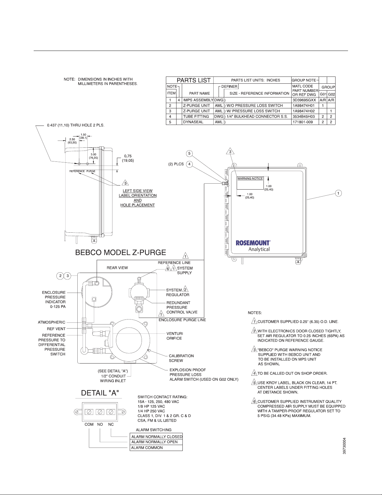
Z-PURGE OPTION Some IMPS applications have area safety requirements (Class 1, Division 2).
These requirements may be satisfied with the installation of an optional
Z-purge. The Z-Purge provides positive pressure within the IMPS 4000
enclosure to keep out dust and other foreign matter. Figure 1-4 shows the
Z-purge unit and how it connects to the IMPS 4000.
SPECIFICATIONS
Feature Specification
Electrical Classification NEMA 4X (IP56)
Humidity Range 95% Relative Humidity
Ambient Temperature Range*
w/o Heater Option
w/ Heater Option
Input Power*
w/o Heater Option
w/ 115 V Nominal Heater (Optional)
w/ 220 V Nominal Heater (Optional)
External Electrical Noise Minimum Interference
Handshake Signal to/from Oxygen
Transmitter (Self-Powered)
Cal Initiate Contact Input from
Control Room (One per Probe) 24 VDC (Self-Powered)
Relay Outputs to Control Room
(One "In-Cal" per Probe, "Low
Gas Flowing," "High Gas
Flowing, "One "Cal Failed" per
Probe, "Gas Pressure Low"
Cabling Distance Between IMPS 4000
and Oxygen Transmitter
Cabling Distance Between IMPS 4000
and Customer-Supplied Status
Relay I/O in Control Room
Piping Distance Between IMPS 4000
and Oxygen Transmitter
Approximate Shipping Weight 40 lbs (18 kg)
*If using the heater option, the low temperature value of the ambient temperature range may vary depending on
the input voltage supply.
32° to 131°F (0° to 55°C)
-35° to 131°F (-37° to 55°C)
90 to 250 V, 50/60 Hz, 50 VA
115 V Nominal, 50/60 Hz, 200 VA
230 V Nominal, 50/60 Hz, 200 VA
5 V (5 mA Maximum)
5 to 30 VDC Form A (SPST),
1.5 A per point, 3 A total per common
1000 ft (303 m) Maximum
1000 ft (303 m) Maximum
300 ft (91 m) Maximum
1-5
4000 IMPS
Figure 1-4. IMPS 4000 with Z-Purge
Instruction Manual
IM-106-400 IMPS, Rev. 2.0
February 2009
1-6
Instruction Manual
IM-106-400 IMPS, Rev. 2.0
February 2009
4000 IMPS
Section 2 Installation
Overview . . . . . . . . . . . . . . . . . . . . . . . . . . . . . . . . . . . . . . . page 2-1
Mechanical Installation . . . . . . . . . . . . . . . . . . . . . . . . . . . page 2-2
Gas Connections . . . . . . . . . . . . . . . . . . . . . . . . . . . . . . . . page 2-3
Electrical Connections . . . . . . . . . . . . . . . . . . . . . . . . . . . . page 2-4
Switch Settings . . . . . . . . . . . . . . . . . . . . . . . . . . . . . . . . . . page 2-6
OVERVIEW This section describes the installation requirements for the IMPS 4000
Intelligent Multiprobe Test Gas Sequencer.
Before starting to install this equipment, read the “Safety Instructions for the Wiring and
Installation of this Apparatus” in Appendix A of this Instruction Manual. Failure to follow the
safety instructions could result in injury or death.
Install all protective equipment covers and safety ground leads after installation. Failure to
install covers and ground leads could result in serious injury or death.
http://www.raihome.com
4000 IMPS
Instruction Manual
IM-106-400 IMPS, Rev. 2.0
February 2009
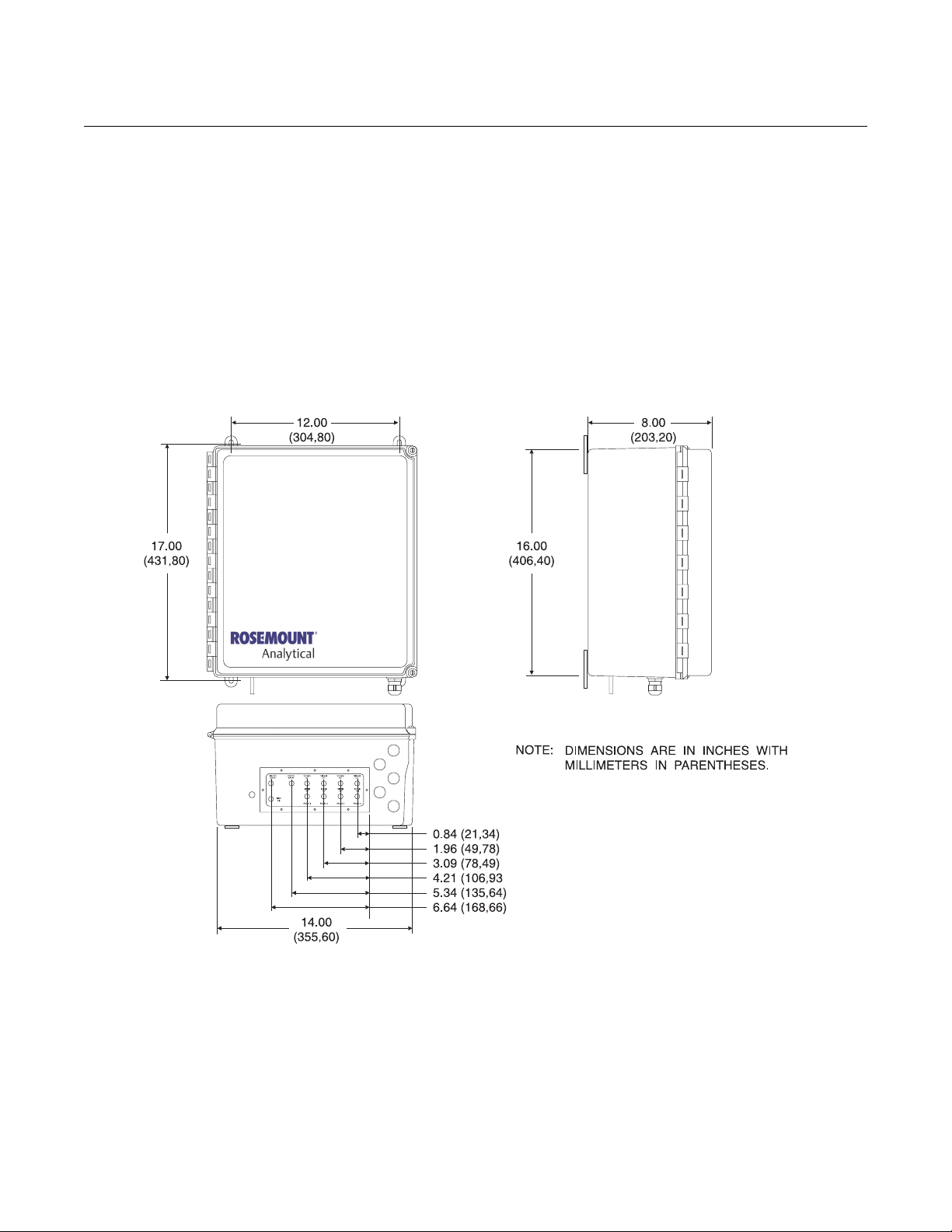
MECHANICAL
INSTALLATION
Figure 2-1. Mounting Dimensions
The outline drawing in Figure 2-1 shows mounting centers and clearances for
the IMPS 4000. The unit is designed to mount on a wall or bulkhead. Ensure
the unit is installed according to the following instructions.
1. Install the module no further than 300 ft (91 m) from the probe and no
further than 1000 ft (303 m) from a remote connection or from the status
relay indicators.
2. Locate units without the optional heater where the ambient temperature
is between 32° and 131°F (0° and 55°C). For units with the optional
heater, install where the ambient temperature is between -35° and
131°F (-37° and 55°C).
2-2
Instruction Manual
IM-106-400 IMPS, Rev. 2.0
February 2009
4000 IMPS
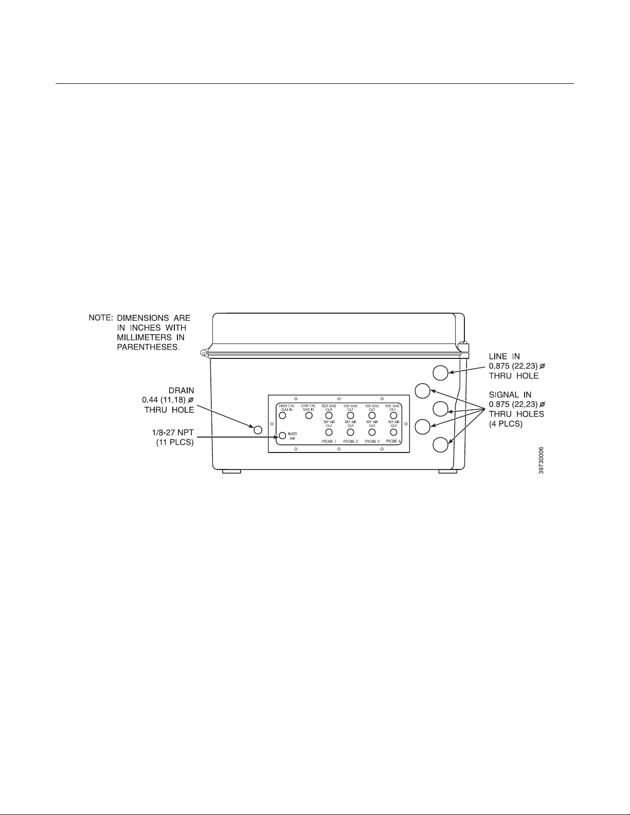
GAS CONNECTIONS Gas connections are located on the bottom of the IMPS 4000 and are 1/8-27
NPT fittings (Figure 2-2). Use the following procedure to connect the test
gases:
1. Connect the reference air supply to INSTR AIR. The pressure regulator
valve is set at the factory to 20 psi (138 kPa). If necessary, readjust by
turning the knob on the top of the valve until the desired pressure is
obtained.
2. Connect the O
should be set at 20 psi (138 kPa).
3. Connect the O
should be set at 20 psi (138 kPa).
4. Connect the oxygen transmitter REF GAS to REF AIR OUT.
5. Connect the oxygen transmitter CAL GAS to TEST GAS OUT.
Figure 2-2. Gas Connections
test gas 1 to HIGH CAL GAS IN. The test gas pressure
2
test gas 1 to LOW CAL GAS IN. The test gas pressure
2
2-3

4000 IMPS
Instruction Manual
IM-106-400 IMPS, Rev. 2.0
February 2009
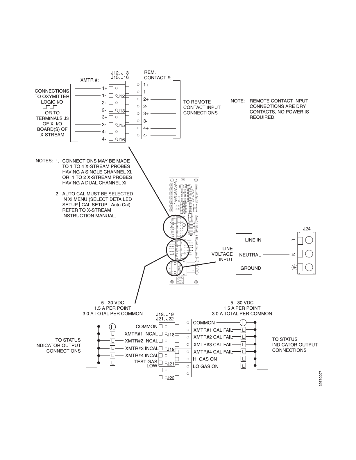
ELECTRICAL
CONNECTIONS
All wiring must conform to local and national codes. Refer to Figure 2-3 and
use the following procedure to connect the first oxygen transmitter. Repeat
the procedure for each remaining oxygen transmitter.
1. Run the line voltage through the bulkhead fitting on the bottom of the
IMPS 4000 marked LINE IN. Connect the line voltage to the J24
terminal. The power supply automatically adjusts to the input voltage.
Tighten the cord grips to provide strain relief.
2. When connecting an Oxymitter O
I/O wires for each oxygen transmitter through a bulkhead fitting on the
bottom of the IMPS 4000 marked SIGNAL IN. Dedicate one fitting for
each oxygen transmitter. Connect the oxygen transmitter logic I/O wires
as shown in Figure 2-3.
3. When connecting an X-STREAM O
signal wires from connector J3 of the Xi I/O board through a bulkhead
fitting on the bottom of the IMPS 4000 marked SIGNAL IN. Dedicate
one fitting for each oxygen transmitter. Connect the oxygen transmitter
handshake signal wires as shown in Figure 2-3.
4. To set up the IMPS 4000 to initiate a calibration from a remote location,
run the remote contact input wires through the SIGNAL IN bulkhead
fitting. Connect the remote contact input wires as shown in Figure 2-3.
5. Status relay connections are available on the IMPS 4000 PC board to
signal when the oxygen transmitter is in or out of calibration and to
indicate calibration gas status. Status relays can be connected to either
indicator lights or a computer interface. Relay contacts are capable of
handling up to 5 to 30 V, 1.5 A per point, 3.0 A total per common
maximum power source. Cabling requirement is 1000 ft (303 m)
maximum. Make the status relay switch connections as shown in
Figure 2-3.
Transmitter, run the handshake logic
2
Transmitter, run the handshake
2
2-4
Instruction Manual
IM-106-400 IMPS, Rev. 2.0
February 2009
Figure 2-3. Electrical Connections
4000 IMPS
2-5
Instruction Manual
IM-106-400 IMPS, Rev. 2.0
4000 IMPS
February 2009
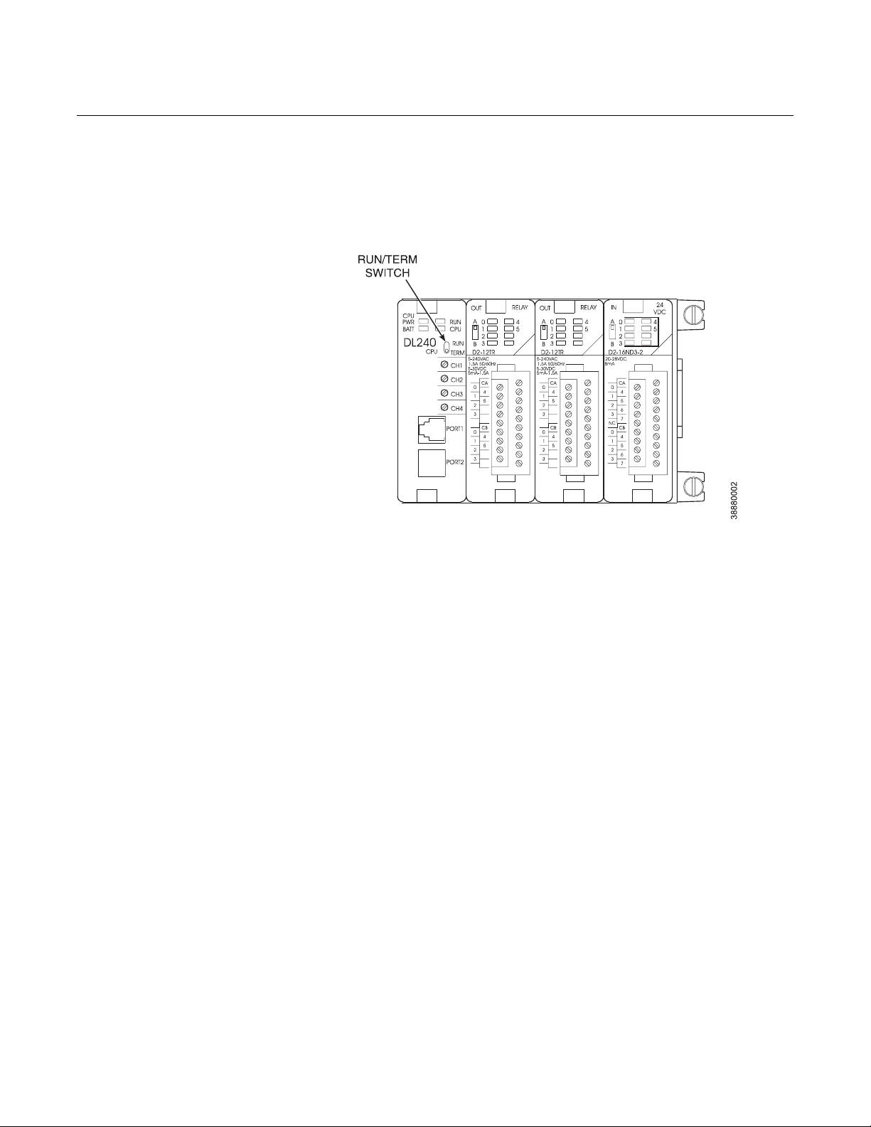
SWITCH SETTINGS The PLC RUN/TERM switch must be in the TERM position for proper
operation. When the RUN/TERM switch is in the RUN position, the PLC will
display an “E525 Keyswitch” error message. Refer to Figure 2-4 and verify
that the RUN/TERM switch is in the RUN position.
Figure 2-4. RUN/TERM Switch
Settings
2-6

Instruction Manual
IM-106-400 IMPS, Rev. 2.0
February 2009
4000 IMPS
Section 3 Operation
Overview . . . . . . . . . . . . . . . . . . . . . . . . . . . . . . . . . . . . . . . page 3-1
Calibration Requirements . . . . . . . . . . . . . . . . . . . . . . . . . page 3-1
Operator Interface Description . . . . . . . . . . . . . . . . . . . . . page 3-2
Message Display Mode Parameters . . . . . . . . . . . . . . . . . page 3-5
Test Gas Flow Setup . . . . . . . . . . . . . . . . . . . . . . . . . . . . . . page 3-6
Automatic Calibration . . . . . . . . . . . . . . . . . . . . . . . . . . . . page 3-6
Semi-Automatic Calibration . . . . . . . . . . . . . . . . . . . . . . . . page 3-7
OVERVIEW This section specifies the requirements to set up an oxygen transmitter
calibration. It describes the PLC operator interface and explains how to set up
time-sequenced calibration routines for up to four oxygen transmitters using
the IMPS 4000. This section also explains the differences between automatic
and semi-automatic calibrations and how to initiate them.
CALIBRATION
REQUIREMENTS
The following components are required for an oxygen transmitter calibration
using the IMPS 4000:
1. Two tanks of precision calibration gas mixtures are required.
Recommended calibration gases are nominally 0.4% and 8.0% oxygen
in nitrogen. Two sources of calibrated gas mixtures are:
LIQUID CARBONIC GAS CORP.
SPECIALTY GAS LABORATORIES
700 South Alameda Street
Los Angeles, California 90058
213/585-2154
767 Industrial Road
San Carlos, California 94070
415/592-7303
9950 Chemical Road
Pasadena, Texas 77507
713/474-4141
12054 S.W. Doty Avenue
Chicago, Illinois 60628
312/568-8840
603 Bergen Street
Harrison, New Jersey 07029
201/485-1995
http://www.raihome.com
255 Brimley Road
Scarborough, Ontario, Canada
416/266-3161
4000 IMPS
Instruction Manual
IM-106-400 IMPS, Rev. 2.0
February 2009
SCOTT ENVIRONMENTAL
TECHNOLOGY, INC.
SCOTT SPECIALTY GASES
2600 Cajon Blvd.
San Bernardino, California 92411
714/887-2571
TWX: 910-390-1159
1290 Combermere Street
Troy, Michigan 48084
314/589-2950
Route 611
Plumsteadville, Pennsylvania 18949
215/766 8861
TWX: 510-665-9344
2616 South Loop West
Suite 100
Houston, Texas 77054
713/669-0469
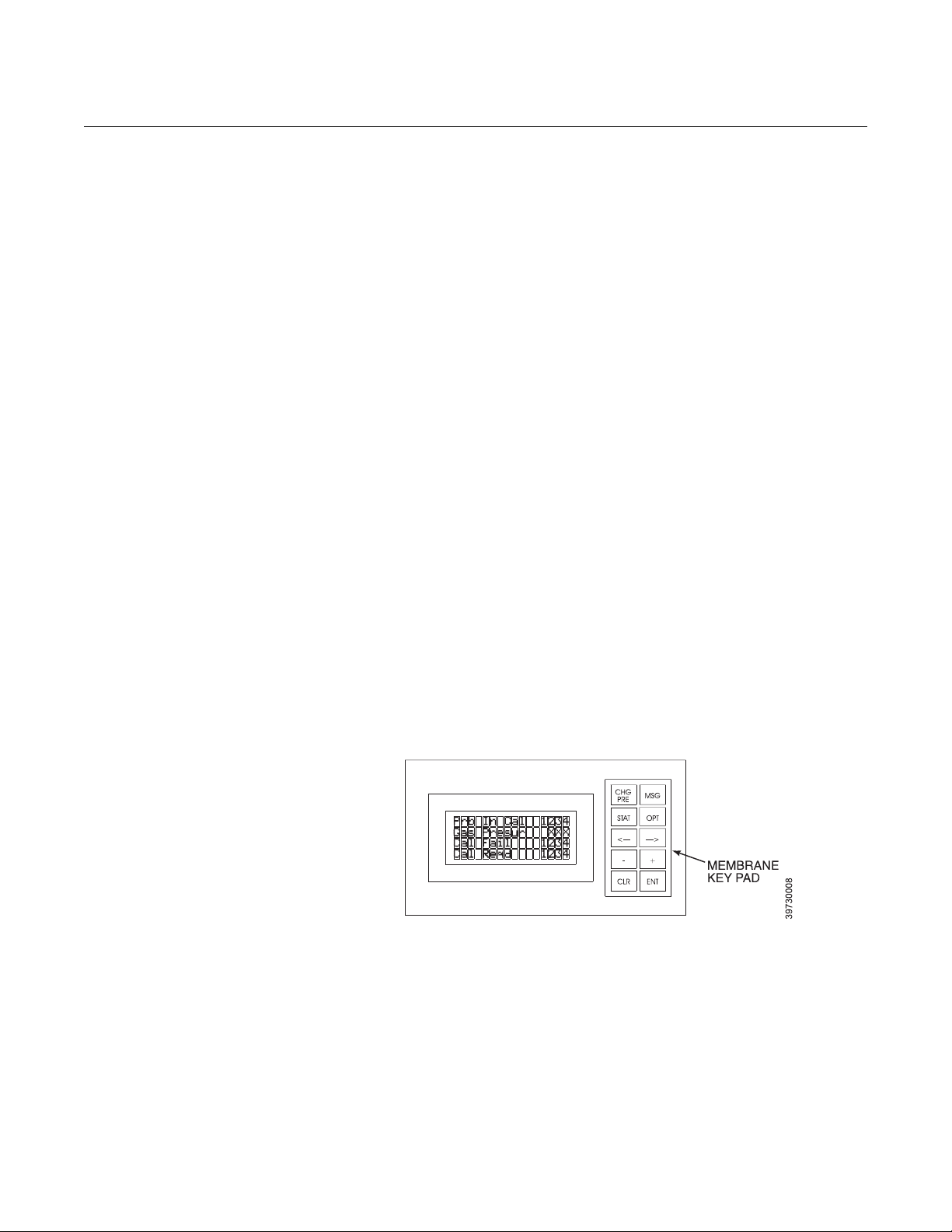
OPERATOR INTERFACE
DESCRIPTION
Figure 3-1. Operator Interface
2. A check valve is required at the oxygen transmitter (between the
calibration fitting and the gas line) to prevent the migration of process
gases down the calibration gas line. A typical calibration setup is shown
in Section 1, Figure 1-3 of this manual.
See Figure 3-1. The operator interface consists of a membrane keypad and a
4-line, 16-character, backlit LCD display. The LCD display is divided into two
areas. The left side is a descriptive field that identifies the calibration
parameter. The right side shows the current value or status of the calibration
parameter.
3-2
 Loading...