


DEWALT Industrial Tool Co., 701 East Joppa Road, Baltimore, MD 21286 |
Printed in U.S.A. (JUN00-CD-1) |
Form No. 153532-02 |
DW744 |
Copyright © 2000 |
|

IF YOU SHOULD EXPERIENCE A PROBLEM WITH YOUR DEWALT PURCHASE,
Before returning this product call
CALL 1-800-4 DEWALT.
IN MOST CASES, A DEWALT REPRESENTIVE CAN RESOLVE YOUR
PROBLEM OVER THE PHONE. 1-800-4-DEWALT IF YOU HAVE A SUGGESTION OR COMMENT, GIVE US A CALL.
YOUR FEEDBACK IS VITAL TO THE SUCCESS OF DEWALT'S
QUALITY IMPROVEMENT PROGRAM.
See our catalog on the World Wide Web at www.dewalt.com
INSTRUCTION MANUAL GUIDE D'UTILISATION MANUAL DE INSTRUCCIONES
INSTRUCTIVO DE OPERACIÓN, CENTROS DE SERVICIO Y PÓLIZA DE GARANTIA. ADVERTENCIA: LEASE ESTE INSTRUCTIVO ANTES DE USAR EL PRODUCTO. SI TIENE DUDAS, POR FAVOR LLAME.
DW744
Table Saw
Scies circulaires à table Sierra de banco
English
 WARNING: FOR YOUR OWN SAFETY, READ INSTRUCTION MANUAL BEFORE OPERATING SAW • ALWAYS WEAR EYE PROTECTION • DO NOT WEAR GLOVES, NECKTIES, JEWELRY OR LOOSE CLOTHING • CONTAIN LONG HAIR • KEEP HANDS AND FINGERS OUT OF THE SAW BLADE PATH — USE EXTRA CAUTION WHEN BEVELING • ALWAYS USE BLADE GUARD AND SPREADER FOR EVERY OPERATION FOR WHICH IT CAN BE USED, INCLUDING THROUGH SAWING • USE A “PUSH STICK” WHEN REQUIRED • KNOW HOW TO AVOID KICKBACKS — SEE MANUAL • ALWAYS SUPPORT WORK WITH TABLE AND FENCE OR MITER GAUGE • NEVER USE FENCE AND MITER GAUGE TOGETHER • NEVER REACH AROUND OR OVER SAW BLADE • SECURE LY MOUNT SAW BLADE BEFORE OPERATING • NEVER REMOVE JAMMED OR CUT-OFF PIECES UNTIL POWER IS OFF AND BLADE HAS STOPPED • DO NOT EXPOSE TO RAIN OR USE IN DAMP LOCATIONS • SECURE TOOL PROPERLY TO PREVENT UNEXPECTED MOVEMENT • DO NOT OPERATE THIS MACHINE WHILE UNDER THE INFLUENCE OF ALCOHOL OR DRUGS • FAILURE TO COMPLY WITH THESE WARNINGS MAY RESULT IN SERIOUS PERSONAL INJURY
DEWALT… BUILT JOBSITE TOUGH
DEWALT high performance industrial tools are made for America’s toughest industrial and construction applications. The design of every tool in the line – from drills to sanders to grinders – is the result of rigorous use on jobsites and throughout industry. Each tool is produced with painstaking precision using advanced manufacturing systems and intense quality control. Every tool is checked before it leaves the factory to make sure that it meets your standards for durability, reliability and power.
DEWALT Built Jobsite Tough…WE GUARANTEE IT.

 WARNING: For your own safety read instruction manual before operating table saw.
 WARNING: When using electric tools, basic safety precautions should always be followed to reduce risk of fire, electric shock, and personal injury, including the following:
Double Insulation
Double insulated tools are constructed throughout with two separate layers of electrical insulation or one double thickness of insulation between you and the tool’s electrical system. Tools built with this insulation system are not intended to be grounded. As a result, your tool is equipped with a two prong plug which permits you to use extension cords without concern for maintaining a ground connection.
NOTE: Double insulation does not take the place of normal safety precautions when operating this tool. The insulation system is for added protection against injury resulting from a possible electrical insulation failure within the tool.
 CAUTION: WHEN SERVICING USE ONLY IDENTICAL REPLACEMENT PARTS. Repair or replace damaged cords.
Polarized Plugs
To reduce the risk of electric shock, this equipment has a polarized plug (one blade is wider than the other). This plug will fit in a polarized outlet only one way. If the plug does not fit fully into the outlet, reverse the plug. If it still does not fit, contact a qualified electrician to install the proper outlet. Do not change the plug in any way.
Important Safety Instructions
•KEEP GUARDS IN PLACE and in working order.
•REMOVE ADJUSTING KEYS AND WRENCHES. Form habit of checking to see that keys and adjusting wrenches are removed from tool before turning it on.
•KEEP WORK AREA CLEAN. Cluttered areas and benches invite injuries.
•DON’T USE IN DANGEROUS ENVIRONMENT. Don’t use power tools in damp or wet locations, or expose them to rain. Keep work area well lighted.
•KEEP CHILDREN AWAY. All visitors should be kept safe distance from work area.
•MAKE WORKSHOP KID PROOF with padlocks, master switches, or by removing starter keys.
•DON’T FORCE TOOL. It will do the job better and safer at the rate for which it was designed.
•USE RIGHT TOOL. Don’t force tool or attachment to do a job for which it was not designed.
•USE PROPER EXTENSION CORD. Make sure your extension cord is in good condition. When using an extension cord, be sure to use one heavy enough to carry the current your product will draw. An undersized cord will cause a drop in line voltage resulting in loss of power and overheating. The following table shows the correct size to use depending on cord length and nameplate ampere rating. If in doubt, use the next heavier gage. The
smaller the gage number, the heavier the cord.
Minimum Gage for Cord Sets
Volts |
|
|
Total Length of Cord in Feet |
|||
120V |
|
0-25 |
26-50 |
51-100 |
101-150 |
|
240V |
|
0-50 |
51-100 |
101-200 |
201-300 |
|
Ampere Rating |
|
|
AWG |
|
||
More |
Not more |
|
|
|||
Than |
Than |
|
|
|
|
|
0 |
- |
6 |
18 |
16 |
16 |
14 |
6 |
- |
10 |
18 |
16 |
14 |
12 |
10 |
- |
12 |
16 |
16 |
14 |
12 |
12 |
- |
16 |
14 |
12 |
Not Recommended |
|
i• WEAR PROPER APPAREL. Do not wear loose clothing, gloves, neckties, rings, bracelets, or other jewelry which may get caught in moving parts. Nonslip footwear is recommended. Wear protective hair covering to contain long hair.
•ALWAYS USE SAFETY GLASSES. Also use face or dust mask if cutting operation is dusty. Everyday eyeglasses only have impact resistant lenses, they are not safety glasses.
•SECURE WORK. Use clamps or a vise to hold work when practical. It’s safer than using your hand and it frees both hands to operate tool.
•DON’T OVERREACH. Keep proper footing and balance at all times.
•MAINTAIN TOOLS WITH CARE. Keep tools sharp and clean for best and safest performance. Follow instructions for lubricating and changing accessories.
•DISCONNECT TOOLS before servicing; when changing accessories, such as blades, bits, cutters, and the like.
•REDUCE THE RISK OF UNINTENTIONAL STARTING. Make sure switch is in off position before plugging in.
•USE RECOMMENDED ACCESSORIES. Consult the instruction manual for recommended accessories. The use of improper accessories may cause risk of injury to persons.
•NEVER STAND ON TOOL. Serious injury could occur if the tool is tipped or if the cutting tool is unintentionally contacted.
•CHECK DAMAGED PARTS. Before further use of the tool, a guard or other part that is damaged should be carefully checked to determine that it will operate properly and perform its intended function–check for alignment of moving parts, binding of moving parts, breakage of parts, mounting, and any other conditions that may affect its operation. A guard or other part that is damaged should be properly repaired or replaced.
•DIRECTION OF FEED. Feed work into a blade or cutter against the direction of rotation of the blade or cutter only.
•NEVER LEAVE TOOL RUNNING UNATTENDED. TURN POWER OFF. Don’t leave tool until it comes to a complete stop.
•REPLACEMENT PARTS. When servicing, use only identical replacement parts.
Additional Safety Rules for Table Saw
 WARNING: For your own safety, do not operate your saw until it is completely assembled and installed according to the instructions and until you have read and understood the following:
• |
All Safety Rules |
• |
Adjustment Procedures |
• |
Assembly Procedures |
• |
Basic Operations |
•Operating Controls
•KEEP GUARDS in place and in working order.
•STABILITY. Make sure table saw is firmly mounted before use.
•MINIMIZE ACCIDENT POTENTIAL. Most accidents are caused by failure to follow setup and operating instructions.
•AVOID awkward hand positions, where a sudden slip could cause a hand to move into a saw blade or other cutting tool. Never reach in back of, or around, the cutting tool with either hand to hold down the workpiece. DO NOT PLACE FINGERS OR HANDS IN THE PATH OF THE SAW BLADE.
•NEVER reach under your machine when operating or make any adjustments when it is running.
•SHUT OFF the saw and disconnect the power cord when removing the table insert, changing the cutting tool, removing or replacing the blade guard, or making adjustments.
•ALWAYS maintain control of the workpiece. DO NOT let go of the workpiece until it is well clear of the cutting tool.
•WHEN REMOVING short workpieces, or cleaning up around the table, be sure the saw is in the OFF position and blade has stopped turning.
•NEVER turn the saw ON before clearing the table of all tools, wood scraps, etc., except the workpiece and related feed or support devices for the operation planned.
English
1

English
•WHEN changing saw location, disconnect power.
•USE extra caution when the guard assembly is removed for resawing, dadoing, rabbeting, or molding. Replace the guard as soon as that operation is completed.
•NEVER hold onto or touch the “free end” of the workpiece or a “free piece” that is cut off, while power is ON and/or the saw blade is rotating.
•IF YOU STALL OR JAM the saw blade in the workpiece, turn saw OFF, remove the workpiece from the saw blade, and check to see if the saw blade is parallel to the miter gauge slots or grooves and if the splitter is in proper
alignment with the saw blade. If ripping at the time, check to see if the rip fence is parallel with the saw blade. Readjust as indicated.
WARNING: Do not allow familiarity (gained from frequent use of your saw) to replace following safety rules. Always remember that a careless fraction of a second is sufficient to inflict severe injury.
•MAKE SURE your fingers do not contact the terminals of the power cord when installing or removing the plug to or from the line power source.
•KICKBACKS - Kickbacks can cause serious injury. A kickback occurs when a part of the workpiece binds between the saw blade and the rip fence, or other fixed object, and rises from the table and is thrown toward the operator. Kickbacks can be avoided by attention to the following conditions:
KICKBACKS—HOW TO AVOID THEM AND PROTECT YOURSELF FROM POSSIBLE INJURY.
a)Be certain that the saw blade is parallel to the rip fence. Adjust fence if not parallel.
b)Do not rip by applying the feed force to the section of the workpiece that will become the cut-off (free) piece. Feed force when ripping should always be applied between the saw blade and the fence…use a push stick for short work, 6" (152mm) wide or less. For less than 2" (51mm) wide, you must use a special fixture.
c)Keep saw blade guard, splitter and anti-kickback teeth in place and operating properly. Keep teeth sharp. If teeth are not operational, return your unit to the nearest DEWALT Service Center for repair. The splitter must be in alignment with the saw blade and the teeth must stop a kickback once it has started. Check their action before ripping by pushing the wood under the anti-kickback teeth. The teeth must prevent the wood from being pulled toward the front of the saw.
d)Plastic and composition (like hardboard) materials may be cut on your saw. However, since these are usually quite hard and slippery, the anti-kickback teeth may not stop a kickback. Therefore, be especially attentive to following proper set up and cutting procedures for ripping.
e)Use saw blade guard and splitter for every operation for which it can be used, including all through sawing.
•DO NOT leave a long board (or other workpiece) unsupported so the spring of the board causes it to shift on the table. Provide proper support for the workpiece,
based on its size and the type of operation to be |
|
performed. Hold the work firmly against the fence and |
|
down against the table surface. |
FIG. 1 |
• NEVER use a length stop on the free end of the |
|
workpiece when crosscutting. Never hang onto or touch |
|
the free end of the workpiece when crosscutting, or a free |
|
piece that is cut off when ripping while power is ON and/or |
|
the saw blade is rotating. In short, the cut-off piece in any |
|
“thru-sawing” (cutting completely through the workpiece) |
|
operation must never be confined — it must be allowed to |
|
move away from saw blade. |
|
• IF YOUR SAW makes an unfamiliar noise or if it vibrates |
|
excessively, cease operating immediately until the source |
|
has been located and the problem corrected. |
|
• KEEP OUT of the line of saw blade. Stand to the side |
|
whenever possible. |
|
• USE a push-stick when required. (See page 9) |
|
•PAY particular attention to instructions on reducing risk of kickback.
•DO NOT perform any operation free hand.
•NEVER reach around, behind or over saw blade.
•USE RECOMMENDED ACCESSORIES. The use of improper accessories may cause risk of personal injury.
 WARNING: Some dust created by power sanding, sawing, grinding, drilling, and other construction activities
contains chemicals known to cause cancer, birth defects or 1 other reproductive harm. Some examples of these chemicals
are:
• lead from lead-based paints,
• |
crystalline silica from bricks and cement and other |
5 |
|
masonry products, and |
|
|
|
|
• |
arsenic and chromium from chemically-treated lumber |
4 |
|
(CCA). |
|
|
|
Your risk from these exposures varies, depending on how |
2 |
|
|
often you do this type of work. To reduce your exposure to |
|
these chemicals: work in a well ventilated area, and work |
|
with approved safety equipment, such as those dust masks |
|
that are specially designed to filter out microscopic particles. |
|
SAVE THESE INSTRUCTIONS |
6 |
3 |
||
FOR FUTURE USE |
||||
|
|
|||
Specifications |
FIG. 2 |
|
||
Horsepower |
2-1/2 |
|
||
|
|
|||
Table Size |
19 1/4" x 26 1/2" |
|
|
|
Miter Angle |
30° L&R |
|
|
|
Bevel Angle |
0° to 45°L |
|
|
|
Blade Size |
10" (254mm) |
|
|
|
Max. Cut Depth |
0° Bevel ................3 1/8" (79mm) |
|
|
|
Max. Cut Depth |
45° Bevel ..............2-1/4" (57mm) |
|
|
|
RPM, no load |
3650 |
|
|
|
2

FIG. 3
TABLE
SCREW-DOWN
HOLES
MITER
GAUGE
MOUNTING
HOLES
ON-OFF SWITCH
BLADE GUARD
RIP SCALE
INDICATOR
RAIL LOCK
LEVER
FINE ADJUST
KNOB
BLADE HEIGHT
ADJUSTMENT
WHEEL
BEVEL LOCK
LEVER
FIG. 4 |
ANTI-KICKBACK TEETH |
WORK SUPPORT
EXTENSION (RETRACTED)
DUST EXHAUST
BLADE/WRENCH
STORAGE
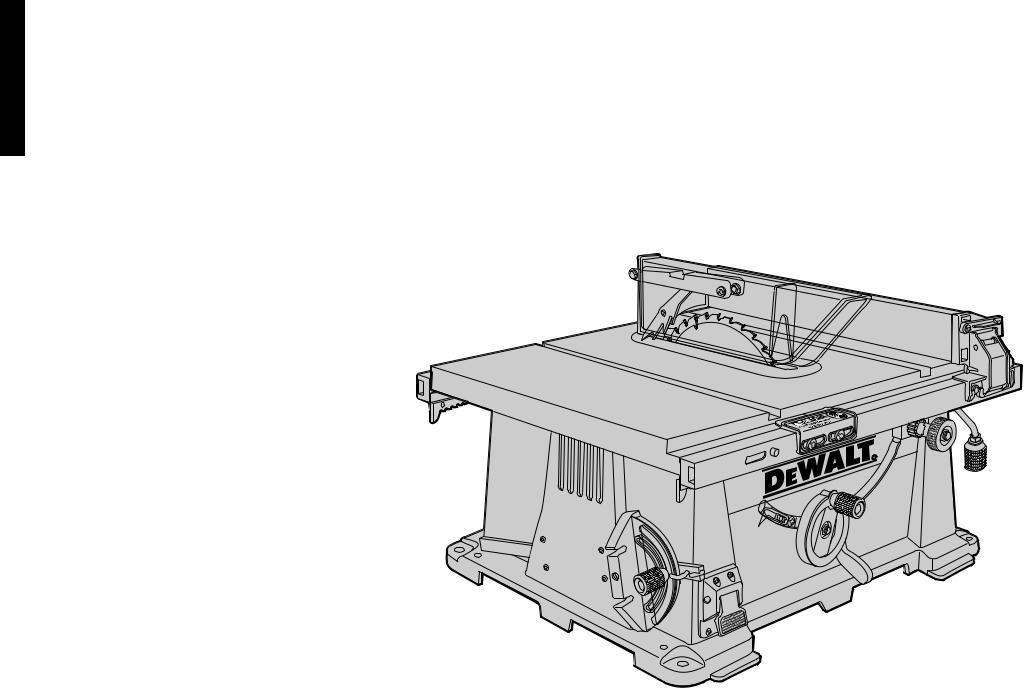
Unpacking
Open the box and slide the saw out , as shown in Figure 1.
Carefully unpack the table saw and all loose items from the carton. Examine all parts to make sure that parts have not been damaged during shipping. If any parts are missing or damaged, contact your dealer to replace them before attempting to assemble the tool.
Figure 2 shows all the loose items and hardware packed with the saw.
1.Rip fence
2.Blade (attached to saw base)
3.Arbor wrench and spindle wrench (attached to saw base)
4.Blade guard
5.Throat plate
6.Miter gauge
Examine Figures 3 & 4 to become familiar with the saw and its various parts. The following sections on assembly and adjustments will refer to these terms and you must know what and where the parts are.
Assembly
YOUR SAW SHOULD BE ASSEMBLED IN THE FOLLOWING ORDER:
1.Blade
2.Rip fence (NOTE: Adjust rip scale before proceeding. See “Adjusting Rip Scale” below.)
3.Blade guard
4.Throat plate
Tools needed for assembly include a screwdriver and the wrenches included with your saw.
ASSEMBLING THE RIP FENCE
The rip fence can be installed on the left or right side of your table saw.
FIG. 5
PIN
OPENING
English
3

English
1.Locate the pin and opening on fence rails, as shown in Figure 5. Align the pin with the slot and align the latch with the opening.
2.Secure the rip fence by snapping the latches onto the rails as shown in Figure 6. Be sure to snap both latches in place.
ATTACHING/REPLACING THE BLADE
1.Raise the saw blade arbor to its maximum height by turning the blade height adjustment wheel clockwise.
2.Remove the arbor nut and flange from the saw arbor by turning counterclockwise.
3.Place the saw blade on to the spindle making sure the teeth of the blade point down at the front of the table. Assemble the washers and arbor nut to the spindle and tighten arbor nut as far as possible by hand, making sure that the saw blade is against the inner washer and the large washer diameters are against the blade. Ensure the side of outer washer marked “Blade Side” is against the blade (see Figure 7). Ensure the spindle and washers are free from dust and debris.
4.To keep the spindle from rotating when tightening the arbor nut, use the open-ended spindle wrench to secure the spindle (see Figure 7A).
5.Using the arbor wrench, tighten the arbor nut by turning it clockwise (see Figure 7A).
6.NOTE: Different types of blades make different kerfs (width of cuts). Therefore, it is necessary to check adjustment of rip fence pointer and blade guard splitter when changing blades.
ADJUSTING THE RIP SCALE
1.Unlock the rail lock lever (see Figure 9).
2.Set the blade at 0˚ bevel and move the fence in until it touches the blade.
3.Lock the rail lock lever.
4.Loosen the rip scale pointer screws (see Figure 16) and set the rip scale pointer to read zero (0). Retighten the rip scale pointer screws. The rip scale reads correctly only when the fence is mounted on the right side of the blade.
ATTACHING THE BLADE GUARD
1.Raise the saw blade arbor to its maximum height by turning the blade height adjustment wheel clockwise.
2.Loosen, but do not remove the two bolts shown in Figure 10.
3.Insert the blade guard as shown in Figure 11, ensuring the bolts fit into the slots on the blade guard. The edge of the splitter should protrude below and hook under the shims. Tighten the bolts. Make sure the splitter is centered and parallel to the blade by lining up the parts with a straight edge. If the blade and splitter are not aligned, loosen, but do not remove the bolts again. Remove the guard and reinsert it after adjusting the shims. These shims allow for precision alignment of the
blade and splitter. Tighten the bolts securely. Make that there is clearance between the splitter and blade, and that the blade spins freely. If the
tilted relative to the blade, the splitter plate until it lines up correctly.
IMPORTANT: THE GUARD SHOULD BE IN ALL POSSIBLE CUTS.
4. Retighten the bolts securely.
 WARNING: Before connecting the table saw power source or operating the saw, always guard and splitter for proper alignment and
saw blade. Check alignment after each change angle.
When properly aligned, the splitter will be in line blade at both table top level, and at the top of Check using the straight edge. With power operate the blade tilt and height adjustments
extremes of travel and insure the guard clears the blade in all operations and that the anti-kickback teeth are functioning.
ATTACHING THE THROAT PLATE
1.Align the throat plate as shown in Figure 12, and insert the tabs on the back of the throat plate into the holes on the back of the table.
2.Press down on the front of the throat plate to snap it into place.
3.The throat plate includes four adjustment screws which raise or lower the throat plate. When properly adjusted, the front of the throat plate should be flush or slightly below the surface of the table top and secured in place. The rear of the throat plate should be flush or slightly above the table top.
4.Turn the cam lock screw (Detail Fig. 12) clockwise 1/4 turn to lock the throat plate in place.
 CAUTION: The throat plate must be in place at all times.
Bench Mounting
FIG. 6
FIG. 7
SPINDLE
ARBOR
NUT
INNER |
OUTER |
WASHER |
WASHER |
|
BLADE |
TURN OFF AND UNPLUG TABLE SAW |
|
FIG. 7A |
Rear Pinion Bearing Assembly |
|
|
||
The table saw must be mounted firmly. The mounting |
|
Torx Head Bolts |
|
surface must have a 15" by 20" opening to allow dust |
|
||
|
|
||
to escape. |
|
|
Rear Pivot |
Four holes are provided in the tool’s feet for mounting. We |
|
||
|
Bracket |
||
strongly recommend that these holes be used to anchor the |
|
||
|
|
||
table saw to your workbench or other stationary rigid frame. |
|
|
|
Alternately, to enhance the saw’s portability, it can be |
|
|
|
mounted to a piece of wood that can be “C” clamped to |
|
|
|
your work surface, stand or Workmate® |
Workcenter. The |
|
|
DEWALT DW7440 Table Saw Stand is designed for use |
|
10mm Hex Bolts |
|
with this saw, and is available from your local DEWALT |
|
||
|
|
||
dealer or service center. |
|
|
|
CAUTION: Failure to securely mount the table saw to |
|
|
|
the work surface can be hazardous. |
|
|
(Saw shown upside down for clarity) |
|
|
|
|
4

FIG.8
FIG. 11
ARBOR
WRENCH
EDGE OF
SPLITTER
FIG. 12
FIG. 9
RAIL LOCK LEVER
FIG. 10
SHIMS BOLTS
FIG. 14
FIG. 13
5
1.Center the saw on a square piece of 1/2" (12.7mm) plywood. The plywood must have a 15" by 20" opening to allow dust to escape.
2.Mark the positions of the four mounting holes in the base of the saw with a pencil.
3.Remove the saw and drill 1/4" (6.4mm) holes in the places you have just marked.
4.Position the saw over the four holes you drilled in the plywood and insert four 1/4" (6.4mm) machine screws FROM THE BOTTOM. Install washers and 1/4" (6.4mm) nuts on the top. Tighten securely.
5.In order to prevent the screw heads from marring the surface to which you clamp the saw, attach two strips of scrap wood to the bottom of the plywood base. These strips can be attached with glue, or wood screws can be installed from the top side as long as they don’t protrude through the bottom of the strip.
6.“C” clamp the plywood base to your workbench whenever you want to use the saw.
 CAUTION: Make sure table saw is firmly mounted before use.
Connecting Saw to Power Source
IMPORTANT: Before connecting saw to power source, make sure the switch is in the OFF position.
Be sure your power supply agrees with the nameplate marking. AC ONLY means that your saw will operate on alternating current only. A voltage decrease of 10 percent or more will cause a loss of power and overheating. All DeWalt tools are factory tested. If this tool does not operate, check the power supply.
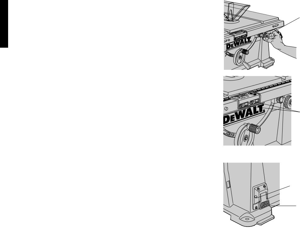
Rip Fence Operation
RAIL LOCK LEVER
The rail lock lever locks the rip fence rails in place, preventing their movement. To lock the rail lock lever, push it down. To unlock the lever, pull it up (see Figure 9). NOTE: When ripping, always lock the rail lock lever.
WORK SUPPORT EXTENSION
Your table saw is equipped with a work support extension to support work that extends beyond the saw table. To use the work support extension, rotate it as shown in Figure 13. When not in use, the work support extension retracts, as shown in Figure 14. NOTE: Retract the work support extension whenever working over the table.
FINE ADJUST KNOB
The fine adjust knob (shown in Figure 15) allows smaller adjustments when setting the fence. Before adjusting, be sure the rail lock lever is in its up, or unlocked, position.
RIP SCALE POINTER
NOTE: The rip scale pointer will need to be readjusted whenever a thicker or thinner blade is installed.
English
English
On-Off Switch
Lift the switch paddle up to turn your saw ON and push it down to turn your saw OFF.
A hole is provided in the switch for insertion of a padlock to lock the saw off (Figure 17).
 WARNING: Be sure switch is in the OFF position before plugging machine in.
Adjustments
NOTE: All settings on your saw have been accurately adjusted at the factory.
RAIL LOCK ADJUSTMENT
1.Lock the rail lock lever (Figure 9) by pushing down.
2.On the underside of your saw, tighten the nut shown in Figure 18. Adjust this nut until the gap between the belville washers closes.
3.Once the springs are almost touching, tighten the nut 1/2 turn.
RIP SCALE ADJUSTMENT
See “ADJUSTING THE RIP SCALE” on page 4.
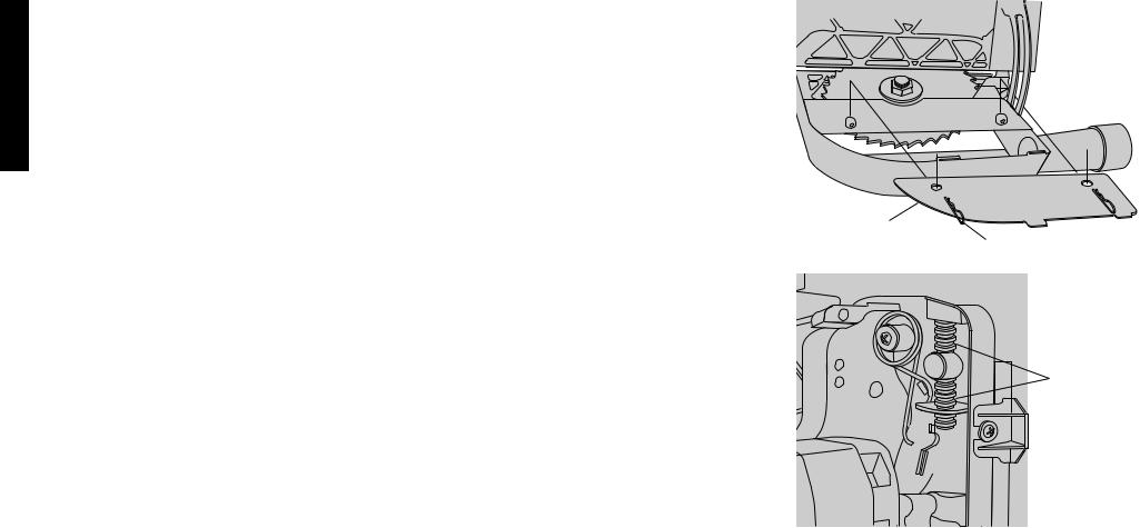
ADJUST BLADE ALIGNMENT TO TABLE
1.THE SAW MUST BE UNPLUGGED BEFORE YOU MAKE ANY ADJUSTMENT TO THE BLADE.
2.Place the unit in an upright position. Using a 10mm socket, loosen rear pivot bracket fasteners just enough to allow the bracket to move side-to-side.(Figure 8)
3.Adjust the bracket until the blade is parallel to the miter gauge slot.
4.Tighten the rear pivot bracket fasteners to 7-8 ft.lbs.
BEVEL STOP AND POINTER ADJUSTMENT
1.Raise the blade fully by rotating the blade height adjustment wheel clockwise until it stops.
2.Unlock the bevel lock lever (Figure 3) by pushing it up and to the right. Loosen the bevel stop screw (Figure 19).
3.Place a square flat against the table top and against the blade between teeth, as shown in Figure 20. Ensure the bevel lock lever is in its unlocked, or up, position.
4.Using the bevel lock lever, adjust the bevel angle until it is flat against the square.
5.Tighten the bevel lock lever by pushing it down.
6.Turn the bevel stop cam until it firmly contacts the bearing block. Tighten the bevel stop screw.
7.Check the bevel angle scale. If the pointer does not read 0°, loosen pointer screw (see Figure 19) and move the pointer so it reads correctly. Retighten the pointer screw.
8.Repeat at 45°, but do not adjust pointer.
MITER GAUGE ADJUSTMENT
Your miter gauge features adjustable stops at 90° and 45°
left and right. To adjust these stops, loosen the lock nuts and tighten or loosen the three adjusting screws against the stop plate (see Figure 21).
FENCE PARALLEL ADJUSTMENT
1.Unlock rail lock lever.
2.Locate rear pinion bearing and loosen the two hex bolts
just enough to allow side-to-side movement. 3. Adjust fence parallel to blade.
4. Lock rail lock lever and check parallel alignment of the blade.
5. Tighten the 2 hex bolts that secure the rear pinion bearing assembly to the table.
NOTE: If there is not enough travel in the pinion bearing assembly to allow the fence to be parallel to the blade, take the unit to an authorized service center.
RACK AND PINION MESH ADJUSTMENT
Proper adjustment of the rack and pinion mesh is done at the factory. If it should become necessary to adjust the rack and pinion mesh, use the following procedure.
1. Turn the saw upside down and locate the front pinion bearing.
2. Using a narrow blade screw driver or #20 torx driver, access the screw through the slot. Loosen the screw (counterclockwise) until the head touches the inside of the bearing box.
3.Tighten the screw (clockwise) 3/4 of a turn.
4.Repeat procedure for rear pinion bearing.
Saw Blades
THIS SAW IS INTENDED FOR THE USE OF SAW
BLADES 10” IN DIAMETER OR SMALLER
1.The saw blade furnished with your new saw is a 10" (254mm) combination blade, used for cross cutting (across the grain) and ripping (with the grain) through the material. The center hole to fit on the arbor is 5/8" (16mm) diameter (.625"). This blade will produce a good quality cut for most applications.
2.There are many types of blades available to do specific and special jobs such as cross cut only, rip only, hollow ground, thin plywood, paneling, etc.
3.Use only saw blades designed for maximum safe
operating speeds of 5,000 RPM or greater.
4. Saw blades should always be kept sharp. It is recommended that you locate a reputable sharpening service to sharpen your blades when needed.
5.Never stack blades on top of one another to store. Place material such as cardboard between them to keep the blades from coming in contact with one another.
 CAUTION: Abrasive wheels should not be used on this saw.
FIG. 17
FINE ADJUST KNOB
FIG. 15
SCREWS
FIG. 16
PADLOCK
INSERTION
HOLE
ON-OFF
SWITCH
6
FIG. 18
BELVILLE
WASHERS
GAP
NUT
BEVEL
STOP CAM
WARN |
ING |
|
FIG. 19
POINTER
BEVEL STOP SCREW
SCREW
FIG. 21
LOCK HANDLE
NUT
STOP PLATE
ADJUSTING
SCREW
FIG. 22
PUSH STICK
FIG. 23
FIG. 20
7
Kickback
Kickback is a dangerous condition! It is caused by the workpiece binding against the blade. The result is that the workpiece can move rapidly in a direction opposite to the feed direction. During kickback, the workpiece could be thrown back at the operator. It can also drag the operator’s hand back into the blade if the operator’s hand is at the rear of the blade. If kickback occurs, turn the saw OFF and verify the proper functioning of the splitter, anti-kickback teeth and guards before resuming work.
 CAUTION:
1.Always use the guard and make certain it is in good working order. The guard’s splitter helps prevent binding and the anti-kickback teeth on each side of the splitter minimize the possibility of kickback. Use extra caution until the workpiece is through the splitter and has engaged anti-kickback teeth.
2.Do not saw warped, bowed or cupped wood. The workpiece must have one straight, smooth side to go against the rip fence or miter gauge. The workpiece must sit flat on the table without rocking.
3.Do not cut “freehand”. Always use either the rip fence or the miter gauge. Never use both.
4.Use extra care when the guard assembly cannot be used (during dadoing or molding).
5.Support large workpieces carefully. Allowing them to sag or droop can cause kickback.
Operation
Plain sawing includes ripping and cross cutting, plus a few other standard operations of fundamental nature. The following methods feature safety. As with all power tools respecting the tool, using caution and following safe practices will considerably lessen the possibility of personal injury. However, if normal safety precautions are overlooked or completely ignored, personal injury to the operator can result. Read and follow all warnings indicated on the saw. Through sawing is any operation which renders the material into two separate pieces.Observe the safety rules included in this manual.
THIS SAW IS NOT INTENDED FOR CUTTING METAL.
Operating Instructions
There are two basic types of cuts: ripping and crosscutting. In general, cutting with the grain is ripping and across the grain is crosscutting. However, with man made materials this distinction is somewhat difficult to make. Therefore, cutting a piece of wood to a different width is ripping and cutting across the short dimension is crosscutting. Neither ripping or crosscutting may be done safely freehand! Ripping requires the use of the rip fence and crosscutting uses the miter gauge.
 CAUTION: Before using the saw each and every time verify the following:
English
English
1.Blade is tight.
2.Bevel angle lock knob is tight.
3.If ripping, ensure rail lock lever is tight and fence is parallel to the blade.
4.If crosscutting, miter gauge lever is tight.
5.Guard is in place and working properly.
6.Safety glasses are being worn.
7.The blade guard is properly attached and the anti-kickback teeth are functioning.
Failure to adhere to these common safety rules can greatly increase the likelihood of injury.
Ripping
1.Lock the rip fence by pressing the rail lock lever down. Remove the miter gauge.
2.Raise the blade so it is about 1/8"(3.2mm) higher than the top of the workpiece.
3.Hold the workpiece flat on the table and against the fence. Keep the workpiece about 1" (25.4mm) away from the blade.
 CAUTION: The workpiece must have a straight edge against the fence and must not be warped, twisted or bowed. Keep both hands away from the blade and away from the path of the blade.
4.Turn the saw on and allow the blade to come up to speed. Both hands can be used in starting the cut. When there is approximately twelve (12) inches (305mm) left to be ripped… use only one hand, with your thumb pushing the material, your index and second finger holding the material down and your other fingers hooked over the fence. Always keep your thumb along side your first two fingers and near the fence.
5.Keeping the workpiece against the table and fence, slowly feed the workpiece rearward all the way through the saw blade. Continue pushing the workpiece until it is clear of the guard and it falls off the rear of the table. Do not overload the motor.
6.Never try to pull the workpiece back with the blade turning. Turn the switch off, allow the blade to stop, raise the anti-kickback teeth on each side of the splitter if necessary and slide the workpiece out.
7.When sawing a long piece of material or a panel, always use a work support. A sawhorse, rollers, or out feed assembly provides adequate support for this purpose. The work support must be at the same height as the saw table.
 CAUTION: Never push or hold onto the “free” or “cut off” side of the workpiece.
Bevel Ripping
This operation is the same as ripping except the bevel angle is set to an angle other than zero degrees.
 WARNING: Before connecting the table saw to the
power source or operating the saw, always inspect the guard and splitter for proper alignment and clearance with saw blade. Check alignment after each change of bevel angle.
Ripping Small Pieces
It is unsafe to rip small pieces. It is not safe to put your hands close to the blade. Instead, rip a larger piece to obtain the desired piece. When a small width is to be ripped and the hand cannot be safely put between the blade and the rip fence, use one or more push sticks. A pattern is included on page 9 to make push sticks. Use them to hold the workpiece against the table and fence, and push the workpiece fully past the blade. See Figure 22.
Crosscutting
1.Remove the rip fence and place the miter gauge in the desired slot.
2.Adjust the blade height so that the blade is about 1/8" (3.2mm) higher than the top of the workpiece.
3.Hold the workpiece firmly against the miter gauge with the path of the blade in line with the desired cut location. Keep the workpiece an inch or so in front of the blade. KEEP BOTH HANDS AWAY FROM THE BLADE AND THE PATH OF THE BLADE.
4.Start the saw motor and allow the blade to come up to speed.
5.While using both hands to keep the workpiece against the face of the miter gauge, and holding the workpiece flat against the table, slowly push the workpiece through the blade. See Figure 23.
6.Never try to pull the workpiece with the blade turning. Turn the switch off, allow the blade to stop, and carefully slide the workpiece out.
 CAUTION: Never touch or hold onto the “free” or “cut off” end of the workpiece.
Bevel Crosscutting
This operation is the same as crosscutting except that the bevel angle is set to an angle other than 0°.
 WARNING: Before connecting the table saw to the power source or operating the saw, always inspect the guard and splitter for proper alignment and clearance with saw blade. Check alignment after each change of bevel angle.
Mitering
This operation is the same as crosscutting except the miter gauge is locked at an angle other than 0°. Hold the workpiece FIRMLY against the miter gauge and feed the workpiece slowly into the blade (to prevent the workpiece from moving). See Figure 23.
MITER GAUGE OPERATION
To set your miter gauge, loosen the lock handle and move the miter gauge to the desired angle. The miter gauge has
FIG. 24
DUST ACCESS
DOOR HAIR PIN
COTTERS
FIG. 25
HEIGHT
ADJUSTMENT
THREADS
set stops and 90° and 45° left and right. To rotate the miter gauge beyond these stops, flip the stop plate up, as shown in Figure 21.
Compound Mitering
This is a combination of bevel crosscutting and mitering. Follow the instruction for both bevel crosscutting and mitering.
Dado Cutting
 CAUTION: Do not attempt to stack dado blades thicker than 13/16" (20mm). Do not use dado blades larger than 8" (200mm) diameter. When installing the dado stack, do not include the inner clamp washer. Replace it with the outer clamp washer, then install the blade stack, arbor nut, and tighten with the wrench supplied.
Since dado cuts are not through cuts, the cuts must be performed with the blade guard removed. To remove the blade guard, loosen the two bolts shown in Figure 10 and
8
 Loading...