


|
|
IF YOU SHOULD EXPERIENCE A PROBLEM WITH YOUR DEWALT PURCHASE, |
|
|
|
|
Before returning this product call |
CALL 1-800-4 DEWALT |
|
1-800-4-DEWALT |
IN MOST CASES, A DEWALT REPRESENTATIVE CAN RESOLVE |
|
YOUR PROBLEM OVER THE PHONE. |
|
|
IF YOU HAVE A SUGGESTION OR COMMENT, GIVE US A CALL. |
|
|
YOUR FEEDBACK IS VITAL TO THE SUCCESS OF DEWALT'S |
|
|
|
QUALITY IMPROVEMENT PROGRAM. |
|
|
|
|
|
|
Questions? See us on the World Wide Web at www.dewalt.com
INSTRUCTION MANUAL
GUIDE D'UTILISATION MANUAL DE INSTRUCCIONES
INSTRUCTIVO DE OPERACIÓN, CENTROS DE SERVICIO Y PÓLIZA DE GARANTÍA. ADVERTENCIA: LÉASE ESTE INSTRUCTIVO ANTES DE USAR EL PRODUCTO.
DW734
12-1/2" (318 mm) Heavy-Duty Portable Thickness Planer Raboteuse portative de service intensif de 318 mm (12-1/2 po) Cepillo portátil de 318 mm (12-1/2") para trabajo pesado
Definitions: Safety Guidelines
The definitions below describe the level of severity for each signal word. Please read the manual and pay attention to these symbols.
 DANGER: Indicates an imminently hazardous situation which, if not avoided, will result in death or serious injury.
 WARNING: Indicates a potentially hazardous situation which, if not avoided, could result in death or serious injury.
 CAUTION: Indicates a potentially hazardous situation which, if not avoided, may result in minor or moderate injury.
NOTICE: indicates a practice not related to personal injury which, if not avoided, may result in property damage.
IF YOU HAVE ANY QUESTIONS OR COMMENTS ABOUT THIS OR ANY DEWALT TOOL, CALL US TOLL FREE AT: 1-800-4-DEWALT (1-800-433-9258)
SAVE THESE INSTRUCTIONS
IMPORTANT SAFETY INSTRUCTIONS FOR ALL TOOLS
 WARNING: For your own safety, read the instruction manual before operating the planer. Failure to heed these warnings may result in personal injury and serious damage to the planer. When servicing this tool, use only identical replacement parts. Have damaged cords replaced by an authorized service center.
GROUNDING INSTRUCTIONS
In the event of a malfunction or breakdown, grounding provides a path of least resistance for electric current to reduce the risk of electric shock. This tool is equipped with an electric cord having an equipment-grounding conductor and grounding plug. The plug must be plugged into a matching outlet that is properly installed and grounded in accordance with all local codes and ordinances. Do not modify plug provided — if it will not fit the outlet, have the proper outlet installed by a qualified electrician.
Improper connection of the equipment-grounding conductor can result in a risk of electric shock. The conductor with insulation having an outer surface that is green with or without yellow stripes is the equipment-grounding conductor. If repair or replacement of the electric cord or plug is necessary, do not connect the equipment-grounding conductor to a live terminal.
Check with a qualified electrician or service personnel if the grounding instructions are not completely understood, or if in doubt as to whether the tool is properly grounded.
Use only 3-wire extension cords that have 3-prong grounding plugs and 3-pole receptacles that accept the tool’s plug.
REPAIR OR REPLACE DAMAGED OR WORN CORDS IMMEDIATELY.
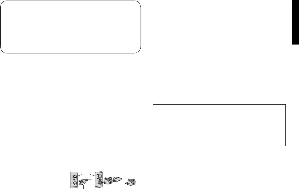
This tool is intended for use on a circuit that |
A |
GROUNDED |
B |
C |
|
has an outlet that looks like the one illustrated |
|||||
|
OUTLET |
|
GROUNDING |
||
in Figure A. The tool has a grounding plug |
|
BOX |
|
||
|
|
MEANS |
|||
that looks like the plug illustrated in Figure A. |
|
|
|
||
|
|
|
|
||
A temporary adapter, which looks like the |
|
|
|
|
|
adapter illustrated in Figures B and C, may |
|
|
|
ADAPTER |
|
be used to connect this plug to a 2-pole |
GROUNDING PIN |
|
|||
receptacle as shown in Figure B if a properly |
|
|
|||
|
|
|
|
||
grounded outlet is not available. The
temporary adapter should be used only until a properly grounded outlet can be installed by a qualified electrician. The green-colored rigid ear, lug, and the like, extending from the adapter must be connected to a permanent ground such as a properly grounded outlet box.
The adapter (C) is not for use in Canada.
 WARNING: When using electric tools, basic safety precautions should always be followed to reduce the risk of fire, electric shock, and personal injury, including the following:
General Safety Instructions
•KEEP GUARDS IN PLACE and in working order.
•REMOVE ADJUSTING KEYS AND WRENCHES. Form habit of checking to see that keys and adjusting wrenches are removed from tool before turning it on.
•KEEP WORK AREA CLEAN. Cluttered areas and benches invite injuries.
•DON’T USE IN DANGEROUS ENVIRONMENT. Don’t use power tools in damp or wet locations, or expose them to rain. Keep work area well lighted. Always operate tool in a well-ventilated area free of combustible materials, gasoline or solvent vapors. If sparks come in contact with flammable vapors, they may ignite, causing fire or explosion.
•KEEP CHILDREN AWAY. All visitors should be kept safe distance from work area.
•MAKE WORKSHOP KID PROOF with padlocks, master switches, or by removing starter keys.
•DON’T FORCE TOOL. It will do the job better and safer at the rate for which it was designed.
•USE RIGHT TOOL. Don’t force tool or attachment to do a job for which it was not designed.
•USE PROPER EXTENSION CORD. Make sure your extension cord is in good condition. When using and extension cord, be sure to use one heavy enough to carry the current your product will draw. An undersized cord will cause a drop in line voltage resulting in overheating and loss of power. The following table shows the correct size to use depending on cord length and nameplate ampere rating. If in doubt, use the next heavier gauge. The smaller the gauge number, the heavier the cord. When operating a power tool outside, use an outdoor extension cord marked “W-A” or “W.” These cords are rated for outdoor use and reduce the risk of electric shock.
Minimum Gauge for Cord Sets
|
|
Volts |
Total Length of Cord in Feet (meters) |
|||
Ampere Rating |
120V |
25 (7.6) |
50 (15.2) |
100 (30.5) |
150 (45.7) |
|
|
|
240V |
50 (15.2) |
100 (30.5) |
200 (61.0) |
300 (91.4) |
More |
Not More |
|
|
AWG |
|
|
Than |
Than |
|
|
|
|
|
0 |
6 |
|
18 |
16 |
16 |
14 |
6 |
10 |
|
18 |
16 |
14 |
12 |
10 |
12 |
|
16 |
16 |
14 |
12 |
12 |
16 |
|
14 |
12 |
Not Recommended |
|
•WEAR PROPER APPAREL. Do not wear loose clothing, gloves, neckties, rings, bracelets, or other jewelry which may get caught in moving parts. Nonslip footwear is recommended. Wear protective hair covering to contain long hair. Air vents often cover moving parts and should also be avoided.
•ALWAYS USE SAFETY GLASSES. Also use face or dust mask it cutting operation is dusty. Everyday eyeglasses only have impact resistant lenses, they are not safety glasses.
•ACTUATING TOOL MAY RESULT IN FLYING DEBRIS, COLLATION MATERIAL, OR DUST WHICH COULD HARM OPERATOR’S EYES. The operator and all those persons in the general area should wear safety glasses with permanently attached side shields. Approved safety glasses are imprinted with the characters “Z87.1”. It is the employer’s responsibility to enforce the use of eye protection equipment by the tool operator and other people in the work area.
•SECURE WORK. Use of clamps or a vise to hold work when practical. It’s safer than using your hands and it frees both hands to operate tool.
•DON’T OVERREACH. Keep proper footing and balance at all times.
•MAINTAIN TOOLS WITH CARE. Keep tools sharp and clean for best and safest performance. Follow instructions for lubricating and changing accessories.
English
1

English
•DISCONNECT TOOLS before servicing; when changing accessories, such as blades, bits, cutters, and the like.
•REDUCE THE RISK OF UNINTENTIONAL STARTING.
Make sure switch is in off position before plugging in.
•USE RECOMMENDED ACCESSORIES. Consult the instruction manual for recommended accessories. The use of improper accessories may cause risk of injury to persons.
•NEVER STAND ON TOOL. Serious injury could occur if the tool is tipped or if the cutting tool is unintentionally contacted.
•CHECK DAMAGED PARTS. Before further use of the tool, a guard or other part that is damaged should be carefully checked to determine that it will operate properly and perform its intended function–check for alignment of moving parts, binding of moving parts, breakage of parts, mounting, and any other conditions that may affect its operation. A guard or other part that is damaged should be properly repaired or replaced.
•NEVER LEAVE TOOL RUNNING UN ATTENDED. TURN POWER OFF. Don’t leave tool until it comes to a complete stop.
Additional Specific Safety Rules for Planers
•To reduce the risk of injury, user must read and understand instruction manual before operating planer.
•Always wear eye protection and dust mask if necessary.
•Keep hands away from the underside of the cutter head carriage.
•Direction of feed. Feed work into planer according to direction of feed arrows on top of the unit.
•Never clear clogs, make cutter knife replacement, or any other repairs/adjustments with unit plugged in.
•Make certain that the switch is in the OFF position before connecting plug to a power source.
•Be sure that the cutter knives are mounted as described in the instruction manual and check that all bolts are firmly tightened before connecting unit to power source.
•To avoid injury, never rotate the cutter block directly with your hands.
•Keep guards in place and in good working order.
•Stay alert – never operate the unit when tired or under the influence of drugs, alcohol, or medication.
•Do not use in dangerous environments. Do not use near flammable substances, in damp or wet locations, or expose to rain.
•Never plane material which is shorter than 12" (304.8 mm) in length.
•Exhaust chute: remove shavings with brush or vacuum after power has been shut off and cutter head has stopped rotating.
•Always secure planer to stable work surface using mounting holes in the base. Refer to Bench Mounting paragraph.
•ALWAYSLOCATEPLANERWITHPROPERCLEARANCE ON THE OUTFEED SIDE of the unit to prevent pinching or binding of the workpiece against any obstacle.
•Clean out your tool often, especially after heavy use.
Dust and grit containing metal particles often accumulate on interior surfaces and could create a risk of serious injury, electric shock or electrocution. ALWAYS WEAR SAFETY GLASSES.
 WARNING: For your own safety, it is recommended that two people carry this machine or serious injury could result.
 WARNING: Wear appropriate personal hearing protection during use. Under some conditions and duration of use, noise from this product may contribute to hearing loss.
 WARNING: Some dust created by power sanding, sawing, grinding, drilling, and other construction activities contains chemicals known to cause cancer, birth defects or other reproductive harm. Some examples of these chemicals are:
•lead from lead-based paints.
•crystalline silica from bricks and cement and other masonry products.
•arsenic and chromium from chemically-treated lumber (CCA).
Your risk from these exposures varies, depending on how often you do this type of work. To reduce your exposure to these chemicals: work in a well ventilated area, and work with approved safety equipment, such as those dust masks that are specially designed to filter out microscopic particles.
•Avoid prolonged contact with dust from power sanding, sawing, grinding, drilling, and other construction activities. Wear protective clothing and wash exposed areas with soap and water. Allowing dust to get into your mouth, eyes, or lay on the skin may promote absorption of harmful chemicals.
 WARNING: A dust mask or respirator should be worn by all persons entering the work area. The filter should be replaced daily or whenever the wearer has difficulty breathing. See your local hardware store for the proper NIOSH/OSHA approved dust mask.
•The label on your tool may include the following symbols. The symbols and their definitions are as follows:
V......... |
volts |
A.......... |
amperes |
||||||
Hz....... |
hertz |
W......... |
watts |
||||||
min ..... |
minutes |
|
|
|
....... |
alternating current |
|||
|
|
|
|
... direct current |
|
|
|
|
alternating or direct |
|
|
|
|
|
|
|
....... |
||
|
|
|
|
Class I Construction |
no |
current |
|||
|
|
|
|
||||||
|
|
....... |
|
||||||
........... |
|
|
|
(grounded) |
no load speed |
||||
|
|
|
|
Class II Construction |
|
|
|
|
earthing terminal |
|
|
|
|
|
|
|
|
||
|
|
....... |
|
|
|
......... |
|
||
........... |
|
|
|
(double insulated) |
|
|
|
........ |
safety alert symbol |
…/min per minute |
BPM .... |
beats per minute |
|||||||
RPM |
... revolutions per minute |
|
|||||||
Specifications
Input ............................ |
120V AC, 15 Amp |
No-load speed ............ |
10,000 RPM |
Feed speed ................. |
26' (7.9 m) per minute |
Planing height ............. |
Maximum 6" (152.4 mm), |
|
Minimum 1/8" (3.2 mm) |
Planing width .............. |
Maximum 12-1/2" (317.5 mm) |
Planing depth.............. |
Maximum 1/8" (3.2 mm) |
|
(for boards 6" (152.4 mm) wide |
|
or less) |
Electrical Connection
Be sure your power supply agrees with the nameplate marking. Volts, 50/60 Hz or “AC only” means your planer must be operated only with alternating current and never with direct current. Voltage decrease of more than 10% will cause loss of power and overheating. All DEWALT tools are factory tested, if this tool does not operate, check the power supply.
Transporting the Planer
 WARNING: For your own safety, it is recommended that two people carry this machine or serious injury could result.
When moving your planer, hold it by the side carrying handles (B) or by the hand indentation (C) at the base of the planer. (Fig. 2).
When transporting or storing the planer, use the cord wrap
(D) located in the back of the tool (Fig. 3) to keep the cord in place.
Bench Mounting
To facilitate bench mounting, two different sized holes (E) are provided on the four corners of your planer as shown in Figure 4. If mounting the planer with bolts, use the larger holes. If mounting the planer with nails or screws, use the smaller holes. It is not necessary to use both sets of holes.
Always mount your planer firmly to a secure surface to prevent movement. To enhance the tool’s portability, it can be mounted to a piece of 1/2" (12.7 mm) or thicker plywood which can then be clamped to your work support or moved to other work areas and reclamped.
NOTE: If you elect to mount your planer to a piece of plywood, make sure that the mounting screws don’t protrude from the bottom of the wood. The plywood must sit flush on the work support.
 CAUTION: The mounting surface should not be warped or otherwise uneven.
ASSEMBLY
 WARNING: To reduce the risk of serious personal injury, turn tool off and disconnect tool from power source before making any adjustments or removing/installing attachments or accessories.
2
Depth Adjustment Crank Handle
TO ATTACH THE DEPTH ADJUSTMENT CRANK HANDLE
1.Insert the crank handle (F) over the shaft (Fig. 5).
2.Secure the crank handle in place with the star screw and T-wrench provided.
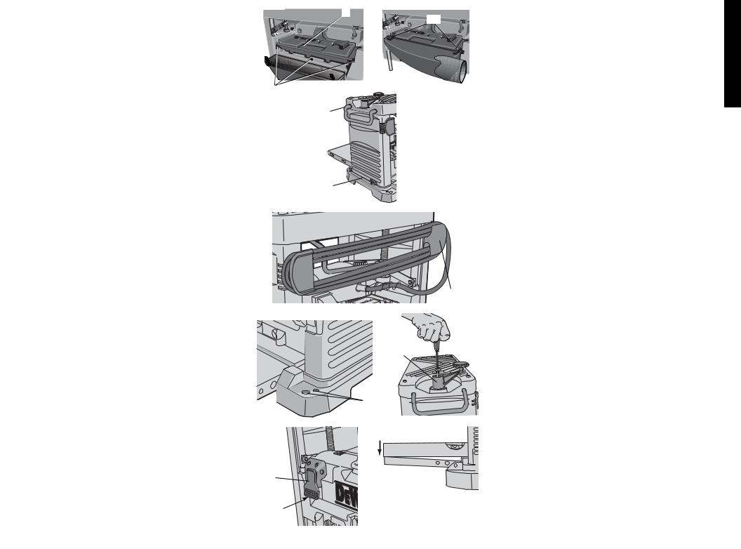
DUST HOOD INSTALLATION (FIG. 1)
1.Remove screws (AA, fig. 1), save these screws.
2.Slide the dust hood clips (BB, fig. 1A) into place on front of the tool tray and rotate dust hood into place.
3Align holes in dust hood with holes in tool tray and motor housing, secure with screws removed earlier.
NOTE: Tighten the bottom screw first and then the two side screws.
4.Attach dust hood to a dust collector. Refer to dust collector owner's manual for correct procedure and safety information.
 CAUTION: When using the dust collection attachment do not operate the unit without a hose connected and a dust collector in operation.
OPERATION
 WARNING: To reduce the risk of serious personal injury, turn tool off and disconnect tool from power source before making any adjustments or removing/installing attachments or accessories.
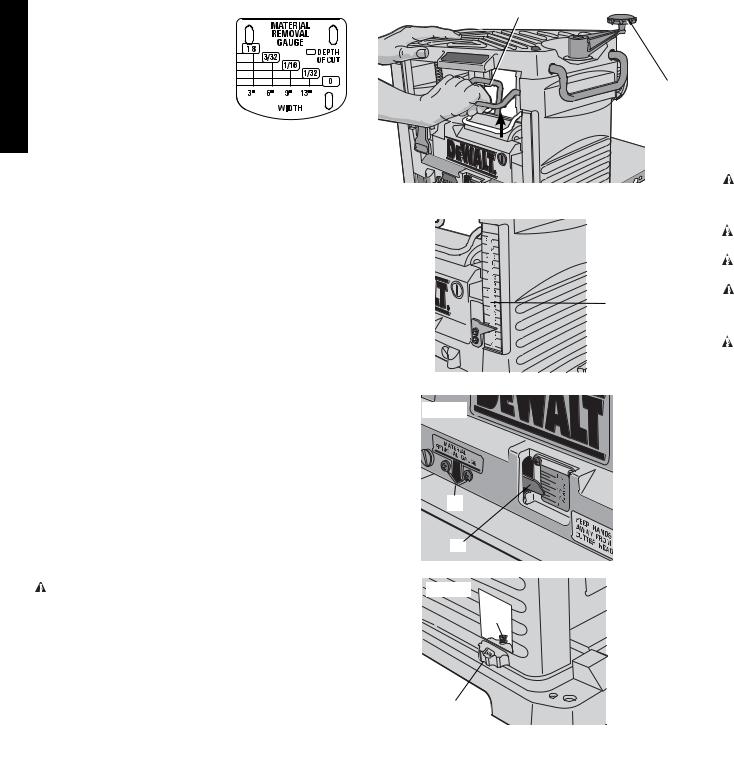
On/Off Switch
To turn the planer on, lift up the switch (G). The planer locks on automatically. To turn the tool off, press the switch down. A hole (H) is provided on the underside of the switch to insert a padlock to lock off the planer as shown in Figure 6.
Table Extensions
Before using your planer, fold down the table extensions in the front and back of the tool (Fig. 7). After extended use, the table extensions may be slightly out of level. See Leveling the Table Extensions in the Maintenance section of this manual.
NOTE: The outside edges of the extension tables are level with the base while the inside edges (closest to the cutter head) are below the edge of the base. This is set at the factory to reduce unnecessary friction between the material and the table while providing adequate support at the two points (those farthest from the cutter head) on the tables that are integral to snipe prevention.
Carriage Head Lock
Your planer is equipped with a carriage head lock lever (I) located on top of the motor (Fig. 8). This device secures the carriage that holds the cutter head to the four posts of your planer. By locking the carriage to the four posts, the movement that causes snipe is drastically minimized.
Depth Adjustment
The depth adjustment scale (J) indicates the finished thickness of your workpiece (Fig. 9). One rotation of the
FIG. 1 |
FIG. 1A |
depth adjustment crank is equal to 1/16" (1.6 mm); half a |
|
|
A |
rotation is equal to 1/32" (0.8 mm), etc. |
|
|
|
BB |
|
|
|
TO SET THE FINISHED THICKNESS |
|
|
|
1. |
Raise head lock lever (I) to unlock the cutter head |
|
|
|
(Fig. 8). This allows the cutter head to be adjusted. |
|
|
2. |
Adjust the thickness. Turn the depth adjustment handle |
|
|
|
(F) clockwise to lower the cutter head. Turn the handle |
|
|
|
counter-clockwise to raise the cutter head. One full |
|
|
|
rotation of the handle moves the cutter head 1/16" |
AA |
FIG. 2 |
|
(1.6 mm). |
|
3. |
Depress the head lock lever to re-lock before planing. |
|
|
|
||
|
B |
NOTE: Do not attempt to adjust the carriage height while |
|
|
the carriage lock is engaged. You may damage the machine. |
||
|
|
||
|
|
FINE ADJUSTMENTS |
|
|
|
The depth adjustment handle allows for fine adjustments, |
|
|
|
from 1/64" (0.4 mm) to 1/16" (1.6 mm). |
|
|
|
Fine adjustments are ideal for “shaving” small amounts |
|
|
|
from your material. For example, if your planed workpiece |
|
|
|
measures 3-1/16" (77.8 mm) thick, but should be 3" |
|
|
C |
(76.2 mm) thick, adjust your planer to remove the excess |
|
|
|
1/16" (1.6 mm) as follows: |
|
FIG. 3 |
|
1. |
Plane and measure your workpiece. In this example, the |
|
|
|
finished thickness is 3-1/16" (77.8 mm). |
|
|
2. |
Turn the circular label on the depth adjustment handle |
|
|
|
until the “0” mark aligns with the arrow on the top of the |
|
|
|
tool. Do not make any other adjustments to the planer. |
|
|
3. |
Turn the depth adjustment handle clockwise until the |
|
|
|
1/16" (1.6 mm) mark aligns with the arrow. |
|
|
4. |
Plane your workpiece. The final thickness should be 3" |
|
|
|
(76.2 mm). |
FIG. 4 |
FIG. 5 |
F
E
FIG. 6 |
FIG. 7 |
G
H
D Material Removal Gauge
Your planer is equipped with a material removal gauge. It is used to indicate the amount of wood that will be removed in one pass with the carriage set at its current height.
TO USE THE MATERIAL REMOVAL GAUGE
 WARNING: DO NOT SWITCH THE UNIT ON WITH THE MATERIAL POSITIONED UNDER THE CARRIAGE. SERIOUS INJURY COULD RESULT.
1. Slide approximately 3" (76.2 mm) of your material under the arrow (K) located in the middle of the carriage (Fig. 10).
2. The wood must lay flat against the base of the planer. If the material is inserted at an angle, the reading may be inaccurate.
3. Unlock and crank the carriage down on the material until the material removal bar engages the wood. The red indicator (L) moves up the scale indicating the amount of material to be removed with the carriage at that height.
4. Adjust the carriage height until the desired depth of cut appears on the gauge.
5.Pull the material out from under the carriage.
6.Lock the carriage lock lever.
7.Turn the unit on and feed your material into the cutter head.
English
3
English
NOTE: |
Do |
not |
exceed |
the |
TABLE A |
FIG. 8 |
I |
Support the workpiece adequately at all times. The maximum |
|||
recommended depth of cut for |
|
|
depth of cut your planer can take in one pass is 1/8" (3.2 |
||||||||
|
|
|
|||||||||
various |
widths |
of |
material |
|
|
|
mm) [on material less than 6" (152 mm) wide]. Never attempt |
||||
recommended |
on |
the |
material |
|
|
|
to modify your planer to take a deeper cut. Follow the depth/ |
||||
removal gauge (Table A). |
|
|
|
|
|
width of cut guidelines shown in Table A for best results. |
|||||
Turret Stop |
|
|
|
|
|
|
1. Lower the carriage to the desired height for your first |
||||
Your planer is equipped with a |
|
|
|
F |
pass. |
|
|||||
turret stop (M), shown in Figure 11, |
|
|
|
2. Turn the unit on and feed the material into the feed |
|||||||
for repetitive planing of pre-set |
|
|
|
|
rollers. |
|
|||||
depths. Stops are set at 0", 1/4" |
|
|
|
3. |
Examine the finished cut and adjust the carriage to the |
||||||
(6.4 mm), 1/2" ( 12.7 mm) and 3/4" (19.0 mm). Use the |
|
|
|
appropriate height for your next pass. |
|||||||
0" setting when planing between 1/8" (3.2 mm) and 1/4" |
|
|
See the Troubleshooting Guide at the end of this section for |
||||||||
(6.4 mm). |
|
|
|
|
|
|
|
|
more information. |
|
|
TO SET A PLANING DEPTH |
|
|
|
|
|
WARNING: Do not place your body between the |
|||||
1. Be sure the carriage is set above 1-1/4" (31.8 mm) |
FIG. 9 |
|
workpiece and a stationary structure while the material is |
||||||||
before trying to set the turret stop. |
|
|
feeding out. Personal injury and/or damage to the work piece |
||||||||
2. Turn the turret stop until the desired measurement |
|
|
may occur. |
|
|||||||
shows (Fig. 11). |
|
|
|
|
|
|
|
WARNING: This tool is designed to plane only wood. Do |
|||
3. Unlock the head lock lever (Fig. 8). Turn the depth |
|
|
not try to plane materials other than wood. |
||||||||
adjustment crank, lowering the carriage by the desired |
|
|
|
WARNING: Never plane wood which is shorter than 12" |
|||||||
increments, until it contacts the turret stop. |
|
|
(304.8 mm) in length. |
|
|||||||
NOTE: DO NOT USE FORCE TO CRANK THE CARRIAGE |
|
|
|
WARNING: Plane only wood that |
is free from foreign |
||||||
BELOW THE LEVEL THAT THE TURRET STOP INDICATES. |
|
J |
objects, with no loose knots and as |
few tight knots as |
|||||||
PERMANENT DAMAGE TO THE HEIGHT ADJUSTMENT |
|
|
possible. Do not plane wood that is severely warped, |
||||||||
SYSTEM ON YOUR PLANER WILL RESULT. |
|
|
twisted, knotted or bowed. |
|
|||||||
NOTE: The 3/4" (19.0 mm) turret stop can be adjusted for |
|
|
|
WARNING: Do not feed wood across the grain, always |
|||||||
other planing thicknesses. Adjusting the 3/4" (19.0 mm) |
|
|
feed wood in the direction of the wood grain. |
||||||||
turret stop does not affect the other turret stop settings. |
|
|
NOTE: For best results, plane both sides of the workpiece |
||||||||
TO ADJUST THE 3/4" (19.0 MM) STOP FOR OTHER |
|
|
to reach a desired thickness. For example, if you need to |
||||||||
THICKNESSES |
|
|
|
|
|
|
remove 1/8" (3.2 mm) from your workpiece, remove 1/16" |
||||
1. Unlock the head lock lever (Fig. 8) and turn the adjustment |
FIG. 10 |
|
(1.6 mm) from each side. This not only allows the workpiece |
||||||||
|
|
to dry with a even moisture content, it also produces finer |
|||||||||
handle counterclockwise to raise the cutter head. |
|
|
|||||||||
|
|
cuts. |
|
||||||||
2. From the back of the tool, locate the turret adjustment |
|
|
|
||||||||
|
|
NOTE: Always plane in the direction of the grain. Planing |
|||||||||
bolt (N) shown in Figure 11. This bolt is set for a 3/4" |
|
|
|||||||||
(19.0 mm) depth of cut at the factory. Use the crescent |
|
|
material less than 3/4" (19.0 mm) wide is not recommended. |
||||||||
wrench provided to loosen the jam nut. Adjust the bolt |
|
|
If you must plane narrow material, group the pieces together |
||||||||
|
|
and plane them as one wide workpiece whenever possible. |
|||||||||
up or down to reach the desired planing depth. |
|
|
|||||||||
K |
|
MINIMUM/MAXIMUM WIDTH/HEIGHT/DEPTH |
|||||||||
3. Turn the depth adjustment crank, lowering the carriage |
|
||||||||||
by the desired increments, until it contacts the turret |
|
|
NOTE: There is a certain area on the carriage of your planer |
||||||||
stop. |
|
|
|
|
|
|
|
|
that will allow the 1/8" (3.2 mm) depth of cut on material less |
||
PLANING BASICS |
|
|
L |
|
than 6" (152.4 mm) wide. See Figure 12 for an approximate |
||||||
|
|
|
|
location of this area. Your material must move under this |
|||||||
Proper Planing Technique |
|
|
|
section of the carriage or planer will not take a 1/8" (3.2 mm) |
|||||||
WARNING: DO NOT TURN THE UNIT ON WITH THE |
FIG. 11 |
|
depth of cut. If the material is wider than 6" (152.4 mm), it will |
||||||||
|
not fit through this area with an 1/8" depth cut. |
||||||||||
MATERIAL ALREADY INSERTED UNDER THE CARRIAGE. |
|
|
|||||||||
N |
|
Snipe |
|
||||||||
WAIT UNTIL THE ROLLERS AND CUTTER HEAD ARE UP |
|
|
|||||||||
TO FULL SPEED BEFORE FEEDING YOUR MATERIAL |
|
|
Snipe is a depression made when an unsupported end of |
||||||||
INTO THE MACHINE. |
|
|
|
|
|
your material bends downward, causing the opposite end |
|||||
TO PLANE YOUR MATERIAL |
|
|
|
|
to lift up into the cutter head. If you are planing material that |
||||||
Your planer works best on lumber with at least one flat |
|
|
is especially long, the use of additional material support is |
||||||||
surface. If both sides of your workpiece are rough, use a |
|
|
recommended. |
|
|||||||
jointer to level one face. |
|
|
|
M |
|
TO AVOID SNIPE |
|
||||
|
|
|
|
|
|
|
|
Feed the workpiece into the planer so it is level and remains |
|||
|
|
|
|
|
|
|
|
|
flat against the base at all times. |
|
|
4

FIG. 12
FIG. 13
FIG. 14
FIG. 15
FIG. 16
BOWED WOOD WILL BE FLATTENED BY FEED ROLLERS AND CUTTER HEAD…
TOP FLAT
BOTTOM FLAT
…BUT BOW WILL RETURN AFTER WOOD IS PLANED
Keep long workpieces level throughout planing operation by receiving or “catching” them from the rear of the planer.
 WARNING: Do not place your body between the workpiece and a stationary structure while the material is feeding out. Personal injury and/or damage to the work piece may occur.
Twisted, Cupped and Bowed Wood
If both sides of your material are very rough or if the material is cupped, bowed or twisted, the planer may not produce the desired result. Ideally, you should have at least one level face/surface on your material before you plane. Your thickness planer will work best with material that has been run through a jointer to produce one flat surface. If you do not have at least one flat surface or a jointer, see the following recommendations:
TO PLANE TWISTED WOOD (FIG. 13)
 WARNING: TWISTED WOOD MAY JAM YOUR THICKNESS PLANER. IF A JAM OCCURS, TURN THE POWER OFF, DISCONNECT THE POWER SUPPLY AND RAISE THE CARRIAGE TO RELEASE THE MATERIAL FROM THE CUTTER HEAD.
To plane only slightly twisted material:
Plane both sides alternating from one to the other until the desired thickness is reached.
TO PLANE CUPPED WOOD (FIG. 14)
To obtain the best possible results with cupped wood:
Rip the material down the middle and plane it as two separate pieces.
NOTE: Ripping the material reduces the severity of the cup and allows the machine to deliver better results. More material will be removed on cupped wood to achieve the desired thickness than on a normal board.
If ripping the material is not an option:
Plane one side of the material until flat, then plane the opposite side until flat (Fig. 15).
NOTE: Do not flip the board back and forth between each pass as recommended by the general planing directions.
TO PLANE BOWED WOOD (FIG. 16)
The feed rollers and cutter head in your planer will push the bow out of the material as it feeds. When the material exits the planer, the pressure of the rollers and cutter head will release allowing the wood to spring back into a bowed formation. To properly remove the bow, use a jointer.
CHANGING THE PLANER KNIVES
 WARNING: To reduce the risk of serious personal injury, turn tool off and disconnect tool from power source before making any adjustments or removing/installing attachments or accessories.
Your planer is equipped with a three-knife cutter head with three blades that have two sharpened edges. These blades can be rotated once and changed as needed.
FIG. 17
FIG. 18 |
FIG. 19
FIG. 20
FIG. 21 |
O |
English
5

English
CHANGE BLADES WHEN:
•dull – may cause feeding issues.
•slow feed or no feed.
•motor overloading can also be an indication that knives are dull and result in frequent breaker trips.
•excessive tearout of the wood material being planed
•nicked – blades can become nicked when planning very knotty wood or when foreign material is not removed from the wood being planed.
TO CHANGE PLANER KNIVES
1.Use the T-wrench to remove the tool tray. The cutter head should now be exposed.
If the eight bolts in the knife clamp ARE NOT visible, use a piece of scrap wood to carefully rotate the cutter head until the bolts are accessible and the cutter head locking lever engages as shown in Figure 21 (O). This will prevent further rotation of the cutter head as you change each knife (Fig. 17).
If the bolts ARE visible, be sure that the cutter head locking lever is engaged so the cutter head does not rotate while you are changing the knives. To do this, use a piece of scrap wood to attempt to rotate the cutter head. The locking lever will click into place if it is not already engaged.
 WARNING: KEEP YOUR FINGERS AWAY FROM THE CUTTER HEAD AT ALL TIMES. USE THE TOOL PROVIDED TO HANDLE THE KNIVES.
2.Remove bolts from knife clamp.
3.Use the magnets on the top of the T-wrench to attract the knife clamp and lift the knife off the cutter head (Fig. 18). One of the knives should now be exposed.
4.Use the magnet on the top of the T-wrench to attract and handle the knife. AVOID TOUCHING THE KNIFE WITH YOUR FINGERS. The knives on your planer are sharpened on both edges.
If only one edge of the knife is worn:
1.Turn the knife around so that the sharp, unused edge hangs over the edge of the cutter head where it will cut the material. Be sure to set the oblong holes in the knife over the pins machined on the cutter head (Fig. 19).
2.To reset the knife clamp, align the beveled edge of the knife clamp with the cutting edge of the knife (Fig. 20). If these are not aligned correctly, the clamp will not secure the knife properly.
3.Place the screws through the holes in the knife clamp and knife into the cutter head.
4.Tighten the screws sufficiently.
To access and replace the other two knives:
1.Depress the cutter head lock lever (O) as shown in Figure 21.
2.Use the piece of scrap wood to carefully turn the cutter head until it locks into place revealing another knife clamp and dull knife.
3.Repeat the procedure indicated above.
If the knives are dull on both edges:
1.Follow the same knife change procedure indicated above. HOWEVER, discard the dull knives and install new ones onto the cutter head. Blades can not be sharpened.
2.Repeat the procedure for the remaining knives.
After installing or reversing the knives:
1.Replace the tool tray onto the unit.
2.Tighten the screws onto the tray.
NOTE: THE PLANER WILL NOT OPERATE IF THE TOOL TRAY IS NOT INSTALLED CORRECTLY.
MAINTENANCE
 WARNING: To reduce the risk of serious personal injury, turn tool off and disconnect tool from power source before making any adjustments or removing/installing attachments or accessories.
Periodic Maintenance
 WARNING: To reduce the risk of serious personal injury, turn tool off and disconnect tool from power source before makinganyadjustmentsorremoving/installingattachments or accessories.
1.Routinely check the tool for damage or broken parts.
2.Clean the unit of dust and debris that has collected in all accessible areas of the planer from planning wood material.
3.Wipe off infeed and outfeed rollers.
4.Clean base table. Light waxing will help wood material pass through the planer.
5.Evaluate blade sharpness condition. Replace as necessary.
6.Gauge Calibration, check thickness gauge calibration and turret stop calibration.
7.Check brushes for wear and replace as necessary.
Installing a New Belt
NOTE: No tools are necessary to install a belt. The use of a screwdriver or other tool to pry or stretch a belt may cause damage to the pulleys and ultimately destroy the new belt.
1.Remove the crank handle.
2.Remove the two hex screws from the top, right side of the planer.
3.Remove the two, small cross head screws securing the side panels to the top of the planer.
4.Lift the side panel up out of the slot in the base and remove the panel from the machine. Notice the grooves inside the belt.
5.Start the belt on the top pulley (P) with 3 grooves on the pulley, as shown in Figure 22.
6.Guide the belt between the lower pulley and the height adjustment screw (Q), as shown in Figure 23.
7.With three grooves engaged on the large pulley, rotate the pulley clockwise. Keep pressure on the edge of the belt to keep the grooves engaged on the small pulley.
FIG. 22
P
FIG. 23 |
|
FIG. 24 |
Q |
FIG. 25 


R
FIG. 26
S
T
6

FIG. 27 |
FIG. 28 |
U |
V
8.Continue pressure on the side of the belt and rotate the large pulley while hopping the belt further onto the pulleys, as shown in Figure 24.
9.All of the belt grooves should be engaged in the final position and the pulleys should rotate smoothly.
10. Reinstall the side cover and the screws. Do not overtighten the self-tapping screws.
Calibrating the Depth Adjustment Scale
The depth adjustment scale on your planer is set at the factory. However, with extended use, the depth adjustment scale could show an incorrect measurement.
TO CHECK THE DEPTH ADJUSTMENT SCALE
1.Plane a piece of wood, noting the measurement on the depth adjustment scale.
2.Measure the finished thickness of the workpiece.
3.If the thickness of the workpiece does not match the reading on the depth adjustment scale, loosen the two cross head screws (R) shown in Figure 25.
4.Adjust the pointer up or down until its reading matches the finished thickness of the workpiece. Securely re-tighten the screws.
Leveling the Table Extensions
After extended use, the table extensions might become slightly out of level. To ensure that the tables are level, place a straight edge on the table extension. The straight edge should contact the edge of the table extension and the main table (Fig. 7). When leveling, press the edge of the table extensions down to remove any play. For best results, use a level long enough to contact the edges of both table extensions.
If the table extensions are not level, loosen the jam nuts (T) and adjust the table extension support bolts (S) up or down (Fig. 26).
NOTE: The outside edges of the extension tables are level with the base while the inside edges (closest to the cutter head) are below the edge of the base. This is set at the factory to reduce unnecessary friction between the material
and the table while providing adequate support at the two points (those farthest from the cutter head) on the tables that are integral to snipe prevention.
TABLE
Keep the table clean and free from oil, grease and pitch. Treat the table with paste wax to help maintain its smooth finish.
Circuit Breaker Reset Button (Fig. 27)
Your planer is equipped with an 18 amp circuit breaker. If your planer becomes overloaded and stops operating, turn off the planer, let the unit sit for 2 minutes and press the reset button (U) before you resume working.
 WARNING: To prevent the planer from starting unexpectedly if power is interrupted by a circuit breaker trip, make sure the switch is in the OFF position before restoring power.
NOTE: Circuit breaker overload is often the result of dull knives. Change your knives on a regular basis to avoid tripping your breaker. Check your knives before re-setting the circuit breaker and continuing to plane.
See the Troubleshooting Guide at the end of this section for more information.
Brushes
Inspect carbon brushes regularly. Keep brushes clean and sliding freely in their guides. Always replace a used brush in the same orientation in the holder as it was prior to its removal.
Carbon brushes have varying symbols stamped into their sides, and if the brushes are worn down to the line closest to the spring, they must be replaced. Use only identical DEWALT brushes.
New brush assemblies are available at DEWALT service centers. After replacing brush assemblies, the tool should be allowed to “run in” (run at no load) for 10 minutes to seat new brushes before using.
TO REMOVE BRUSH ASSEMBLY (FIG. 28)
 WARNING: To reduce the risk of serious personal injury, turn tool off and disconnect tool from power source before making any adjustments or removing/installing attachments or accessories.
1.Remove the brush inspection cap (V).
2.Withdraw the brush assembly.
Cleaning and Lubrication
 CAUTION: Never let any liquid get inside the tool; never immerse any part of the tool into a liquid. Electric shock may result.
 CAUTION: Never use solvents or other harsh chemicals for cleaning the non-metallic parts of the tool.
It is recommended that, once a year, you take or send the tool to a DEWALT certified service center for a thorough cleaning, inspection and lubrication of the gear case.
Accessories
There are three accessories available for the DW734 thickness planer:
•DW7331 – Dust Hood for DW734 (also fits the DW733)
•DW7342 – 12-1/2" (317.5 mm) Disposable Reversible Planer Knives
•DW7350 – Mobile Stand
 CAUTION: The use of any other accessory not recommended for use with this tool could be hazardous.
If you need any assistance in locating these accessories, please contact DEWALT Industrial Tool Co., 701 East Joppa Road, Baltimore, MD 21286 or call 1-800-4-DEWALT (1-800-433-9258).
Repairs
To assure product SAFETY and RELIABILITY, repairs, maintenance and adjustment should be performed by authorized service centers or other qualified service personnel. Always use identical replacement parts.
Three Year Limited Warranty
DEWALT will repair, without charge, any defects due to faulty materials or workmanship for three years from the date of purchase. This warranty does not cover part failure due to normal wear or tool abuse. For further detail of warranty coverage and warranty repair information, visit www.dewalt. com or call 1-800-4-DEWALT (1-800-433-9258). This warranty does not apply to accessories or damage caused where repairs have been made or attempted by others. This warranty gives you specific legal rights and you may have other rights which vary in certain states or provinces.
In addition to the warranty, DEWALT tools are covered by our:
1 YEAR FREE SERVICE
DEWALT will maintain the tool and replace worn parts caused by normal use, for free, any time during the first year after purchase.
90 DAY MONEY BACK GUARANTEE
If you are not completely satisfied with the performance of your DEWALT Power Tool, Laser, or Nailer for any reason, you can return it within 90 days from the date of purchase with a receipt for a full refund – no questions asked.
English
7
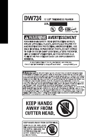
FREE WARNING LABEL REPLACEMENT: If your warning labels become illegible or are missing, call 1-800-4-DEWALT (1-800-433-9258) for a free replacement.
English
Troubleshooting Guide
IF THE MATERIAL DOES NOT FEED PROPERLY, CHECK FOR:
•dull knives, rotate or replace as necessary. Refer to Changing the Planer Knives section.
•excess clogging in the dust hood. Refer Dust Hood Installation paragraph in the Assembly section.
•excess oil/debris/pitch on feed rollers. Refer to Periodic Maintenance and Cleaning and Lubrication paragraphs under the Maintenance section.
•excessively twisted, cupped or bowed material. Refer to Twisted, Cupped and Bowed Wood paragraph in the Basic Planing section.
•a broken drive belt. Refer to Installing a New Belt paragraph in the Maintenance section.
•dull knives. Refer to Changing the Planer Knives section.
IF THE CIRCUIT BREAKER TRIPS REPEATEDLY:
•dull knives, dull knives can cause motor overloading, rotate or replace as necessary. Refer to Changing the Planer Knives section.
NOTE: Circuit breaker overload is often the result of dull knives. If the circuit breaker on your planer trips, check the sharpness of your knives before attempting to reset the breaker in order to continue planing.
•reduce the depth of cut, an overly aggressive cut could cause motor overloading. Refer to Depth Adjustment paragraph in the Operation section.
IF THE UNIT DOES NOT RUN, CHECK TO SEE:
•if the unit is plugged in. Ensure unit is plugged into the appropriate outlet, refer to the Important Safety Instructions for All Tools section.
•if the tool tray is properly in place. Refer to Figure 1 for proper location.
•if the circuit breaker needs to be reset. Refer to Circuit Breaker Reset Button paragraph under the Maintenance section.
•if the motor brushes are depleted, replace as necessary. Refer to Brushes paragraph under the Maintenance section.
8
 Loading...