


If you have questions or comments, contact us. Pour toute question ou tout commentaire, nous contacter.
Si tiene dudas o comentarios, contáctenos.
1-800-4-DEWALT • www.dewalt.com
INSTRUCTION MANUAL
GUIDE D'UTILISATION MANUAL DE INSTRUCCIONES
INSTRUCTIVO DE OPERACIÓN, CENTROS DE SERVICIO Y PÓLIZA DE GARANTÍA. ADVERTENCIA: LÉASE ESTE INSTRUCTIVO ANTES DE USAR EL PRODUCTO.
DW723
Miter Saw Stand
Support de scie à onglets Base para ingleteadora

English
BEAM |
SAW MOUNTING BRACKETS |
DW723 Miter Saw Stand
EXTENSION ARM
|
12'-6" |
(3810 |
mm) |
5'-6" |
|
||
(1480 |
|
||
mm) |
|
||
|
|
||
|
|
|
|
|
|
|
LENGTH |
|
|
|
STOP |
RELEASE BUTTON |
|
|
|
LOCKING |
|
|
LOCATOR |
WORKPIECE |
|
CLIP |
||
SUPPORT |
||
|
||
|
RELEASE LEVERS |
|
CARRY HANDLE |
EXTENSION |
|
|
||
|
ARM END CAP |
5'- |
|
|
|
6" |
(1480 |
mm) |
EXTENSION |
|
|||
|
|
ARM LOCK |
|
|
|
|
KNOB
2

Definitions: Safety Guidelines
The definitions below describe the level of severity for each signal word. Please read the manual and pay attention to these symbols.
 DANGER: Indicates an imminently hazardous situation which, if not avoided, will result in death or serious injury.
  WARNING: Indicates a potentially hazardous situation which, if not avoided, could result in death or serious injury.
  CAUTION: Indicates a potentially hazardous situation which, if not avoided, may result in minor or moderate injury.
CAUTION: Used without the safety alert symbol indicates a potentially hazardous situation which, if not avoided, may result in property damage.
IFYOU HAVE ANY QUESTIONS OR COMMENTS ABOUT THIS OR ANY DEWALT TOOL, CALL US TOLL FREE AT: 1-800-4-DEWALT
(1-800-433-9258)
Miter Saw Stand with Folding Legs DW723
This stand is designed for use with most miter saws. If you have any problem with alignment or mounting, call 1-800-4-DEWALT (1-800-433-9258).
WARNING: For your own safety, read the miter saw  instruction manual before using any accessory. Failure to heed these warnings may result in personal injury and serious damage to the miter saw and the accessory. When
servicing this tool, use only identical replacement parts.
Tools Required
1.Socket or wrench set
2.Drill with 3/8" (9.5 mm) drill bit (Not required for DEWALT Miter Saws)
3.Phillips #2 screwdriver
General Safety Instructions for Miter Saw Accessories
 WARNING: To reduce the risk of personal injury:
•ALWAYS use eye protection. All users and bystanders must wear eye protection that conforms to ANSI Z87.1.
•DO NOT exceed the weight this stand can hold. The main center beam of the miter saw stand is designed to support 500 lbs. (227 kg.) safely in a work environment. It is unsafe to climb, sit or stand on the stand.
•Follow the mounting instructions carefully. Fasten the tool to the saw mounting brackets securely as instructed.
•DO NOT modify or use stand for operations for which it is unintended.
•DO NOT use the stand on uneven surfaces. The stand is designed to be used on a flat, stable surface.
PREPARATION
Lay the miter saw stand on the floor with the folded legs on top. Push the locking pin and pull each leg up until the locking pin (A) clicks into its detent. Lift the stand by the center beam and place it in an upright position. The stand should be stable and should not rock. Check the legs to be sure that the locking pins have engaged and the legs are firmly held in place.
A |
English
1
English
ASSEMBLY
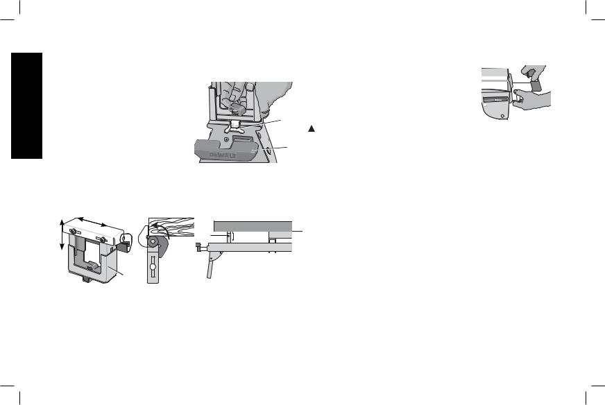
Work Stop/Support
a. The work stop/support has a clamp |
|
(B) to capture the beam and keep |
|
it from being knocked off the beam |
|
by your material. The knob may be |
B |
locked by turning clockwise and |
|
the work stop/support is free to be |
|
repositioned when the knob is |
E |
turned counterclockwise. Do not |
overtighten, firm pressure on the knob will hold the stop in place.
b.Adjust the height of the work stop/support by loosening the knobs on both sides (C) and raise or lower the top surface to align with a straight edge or level to the saw table. Tighten the bolts.
D
 F
F
 C
C
D
c.The work stop/support (D) can also be installed in the end cap
(E)at the end of the extension arms.
d.The length stop (F) may be rotated up to serve as a length stop or hold the end of long work pieces.
Adjustable Length Extension Arm
To lengthen the support surface, turn the beam 

 lock knob counterclockwise to release the

 extendable support arm. Pull the extendable
 extension arm out to the desired length. Turn


 the knob clockwise to lock.


Miter Saw Mounting
 WARNING: To reduce the risk of injury, turn unit off, disconnect machine from power source before assembling the miter saw to the miter saw stand. An accidental start-up can cause injury.
 WARNING: Stability Hazard.You must use the plywood mounting method detailed in step 13 when mounting a miter saw not manufactured by DEWALT to this miter saw stand.
 WARNING: To reduce the risk of personal injury, be sure the miter saw is fully anchored on the stand.
 WARNING: For your own safety, read and understand the miter saw instruction manual before using. Failure to heed these warnings may result in personal injury and serious damage to the miter saw and the accessory.
1.Place saw in operational position with blade facing you. Align with label on the mounting bracket showing front.
2.Place a spacer, such as a 2 x 4, under one side of the miter saw to hold the saw’s mounting feet above the work surface.
3.Hold a mounting bracket under the saw and feed a carriage bolt (hardware bag) up through the bracket and the foot of the saw. NOTE: See DW723 Mounting Procedure Chart for the correct mounting hardware procedures for DEWALT miter saws. Follow all instructions properly, otherwise the miter saw's table rotation will be obstructed.
2

DW723 MOUNTING PROCEDURE CHART
|
Left Side |
Right Side |
DW703 |
1 |
1 |
DW705 |
1 |
1 |
DW706 |
1 |
1 |
DW708 |
1 |
2 |
DW712 |
1 |
2 |
DW713 |
1 |
1 |
DW715 |
1 |
1 |
DW716 |
1 |
1 |
DW717 |
2 |
1 |
DW718 |
3 |
2 |
|
1 = Long screw, Head on bottom |
|
2 = Short screw, Head on bottom
3 = Long screw, Head on top
4.Once the carriage bolt (hardware bag) is installed per Mounting Procedure Chart, assemble a flat washer; lock washer and nut onto the bolt. Tighten the bolts finger tight.
5.Repeat procedure on the other end of the bracket.
6.Move the 2 x 4 to the other side of the saw to hold the other end of the saw up in order to access the saw base.
7.Feed carriage bolts through the other bracket and the base of the saw as before. Ensure both brackets are parallel to each other.
8.To place the saw onto the stand, grasp and lift saw by mounting bracket assembly by the release levers. These levers do not lock the saw laterally in place but merely serve as a means of mounting the saw to the beam.
9. Approach the beam with saw/bracket |
|
assembly tilting toward your body slightly. |
|
Engage the concave front lip of the mounting |
|
bracket with rounded edge of beam. One of |
|
the brackets must engage the locator clip |
G |
(G) to prohibit lateral movement of the saw |
|
during use. |
|
10.When front edge of the beam and locking locator clip are engaged, a slight downward pivot will allow secure engagement of the rear levers to back of beam. Rock the saw gently on the brackets to verify locking in position.
11.Adjust the saw position as necessary to have the blade perpendicular to the beam when in the 0 degree miter position.
12.Tighten the four nuts holding the saw to the brackets securely.
English
3
English
 WARNING: For your own safety, read and understand the miter saw instruction manual before using. Failure to heed these warnings may result in personal injury and serious damage to the miter saw and the accessory.
13.The miter saw MUST be positioned so all four corners can be bolted squarely to the mounting brackets. If this is not possible, please call DEWALT Customer Support at 1-800-4-DEWALT (1-800-433-9258) for technical assistance.
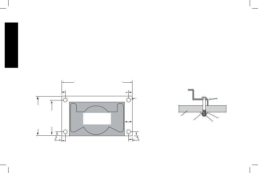
NOTE: If the saw mounting holes do not line up with the slots in the mounting brackets, mount the saw to a piece of 3/4" (19 mm) plywood. The plywood must be a minimum of 4" (101.6 mm) wider than the miter saw base being mounted and a minimum depth of
16" (406.4 mm). Plywood must be at least as deep as the saw base being mounted. Place the mounting brackets on the stand and mount the plywood board to the mounting brackets exactly as shown in figure. Drill 3/8" (9.4 mm) holes 1" (2.5 mm) from each end to secure plywood to mounting brackets. Other hardware (not supplied) may be necessary under these circumstances. NOTE: All purchased hardware must be a minimum of Grade 2. Hardware should be 1-1/4" (31,8 mm) longer than the saw base you are assembling. NOTE: If the saw mounting holes do not line up with the slots in the mounting brackets and the method of utilizing plywood does not accommodate your saw, please call 1-800-4-DEWALT (1-800-433- 9258) for additional hardware to install your miter saw.
|
|
WIDTH OF SAW + 4" (101.6 mm) |
||
|
|
1" (2.5 mm) |
1" (2.5 mm) |
|
MINIMUM OF |
|
|
|
|
16" (406.4 mm) |
15" |
|
|
|
MUST BE AT |
|
MOUNT MITER |
||
((381 mm) |
|
|||
LEAST AS |
|
|||
SAW IN SHADED |
||||
BOTH |
||||
DEEP AS THE |
||||
|
AREA |
|||
SIDES |
|
|||
SAW BEING |
|
|||
|
|
|||
|
|
|
||
MOUNTING |
|
|
|
|
1" (2.5 mm) |
|
|
||
3/8" (9.5 mm) |
|
|
DIAMETER |
SAW |
|
HOLES, ALL |
||
BASE |
||
4 CORNERS |
||
|
|
3/4" (19 mm) |
|
FLAT |
|
2" (50.8 mm) |
|
WASHER |
||
PLYWOOD |
LOCK |
|
||
MINIMUM |
NUT |
|||
|
||||
BOTH SIDES |
|
WASHER |
|
|
1" (2.5 mm) |
|
|
|
4
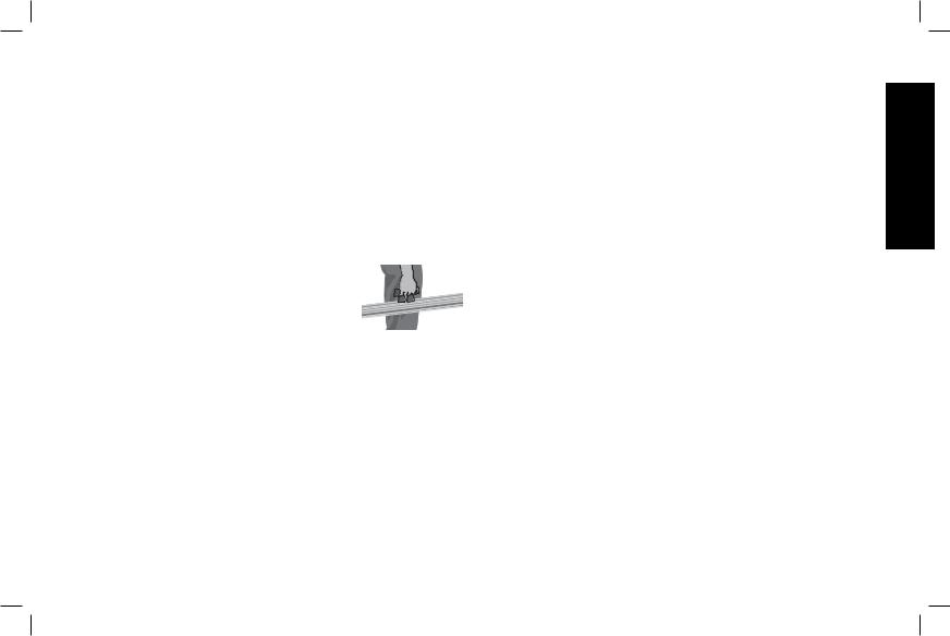
Locking Locator Clip
The locking locator clip (G) keeps the saw from sliding left or right during cutting operations. To move the clip, remove saw/bracket assembly, loosen the screw in the center of the clip, slide it to the desired position and tighten the screw. You can then remount the saw/bracket in the new location.
Removing the Saw
Once the miter saw is fastened to the brackets, it can be removed by grasping the release levers, pulling up slightly to clear the beam and can be set down on the rubber feet for transportation or cleaning.
Carry Handle
A handle has been supplied to safely transport the Miter Saw Stand to and from the work site.
 WARNING: To reduce the risk of personal injury, DO NOT attempt to store the stand – with or without the saw attached – in a vertical position. Loss of control may result.
Accessories
 WARNING: Since accessories, other than those offered by DEWALT, have not been tested with this product, use of such accessories with this tool could be hazardous. To reduce the risk of injury, do not create unstable conditions and use only with DEWALT miter saws.
Recommended accessories for use with your tool are available at extra cost from your local dealer or authorized service center. If you need assistance in locating any accessory, please contact DEWALT Industrial Tool Co., 701 East Joppa Road, Baltimore, MD 21286, call 1-800-4-DEWALT (1-800-433-9258) or visit our website www. dewalt.com.
Repairs
To assure product SAFETY and RELIABILITY, repairs, maintenance and adjustments should be performed by a DEWALT factory service center, a DEWALT authorized service center or other qualified service personnel. Always use identical replacement parts.
Three Year Limited Warranty
DEWALT will repair, without charge, any defects due to faulty materials or workmanship for three years from the date of purchase. This warranty does not cover part failure due to normal wear or tool abuse. For further detail of warranty coverage and warranty repair information, visit www.dewalt.com or call 1-800-4-DEWALT (1-800-433-9258). This warranty does not apply to accessories or damage caused where repairs have been made or attempted by others. This warranty gives you specific legal rights and you may have other rights which vary in certain states or provinces.
In addition to the warranty, DEWALT tools are covered by our:
1 YEAR FREE SERVICE
DEWALT will maintain the tool and replace worn parts caused by normal use, for free, any time during the first year after purchase.
English
5

English
90 DAY MONEY BACK GUARANTEE
If you are not completely satisfied with the performance of your DEWALT Power Tool, Laser, or Nailer for any reason, you can return it within 90 days from the date of purchase with a receipt for a full refund – no questions asked.
LATIN AMERICA: This warranty does not apply to products sold in Latin America. For products sold in Latin America, see country specific warranty information contained either in the packaging, call the local company or see website for warranty information.
FREE WARNING LABEL REPLACEMENT: If your warning labels become illegible or are missing, call 1-800-4-DEWALT (1-800-433-9258) for a free replacement.
6
 Loading...