


DW788/383329 8/6/02 10:35 AM Page 2
DEWALT Industrial Tool Co., 701 East Joppa Road, Baltimore, MD 21286 |
(JUN00-2) |
Form No. 383329 |
|
DW788 |
Copyright © 1997,2000 |
|
|

DW788/383329 8/6/02 10:35 AM Page 3
INSTRUCTION MANUAL GUIDE D'UTILISATION MANUAL DE INSTRUCCIONES
INSTRUCTIVO DE OPERACIÓN, CENTROS DE SERVICIO Y PÓLIZA DE GARANTÍA.ADVERTENCIA: LÉASE ESTE INSTRUCTIVO ANTES DE USAR EL PRODUCTO.
DW788
20" (508 mm) Heavy Duty Variable Speed Scroll Saw
Scie à découper de service intensif de 508 mm (20 po) à régulateur de vitesse Sierra caladora de 508 mm (20") con velocidad variable para trabajo pesado
DW788/383329 8/6/02 10:35 AM Page 4
English
IF YOU HAVE ANY QUESTIONS OR COMMENTS ABOUT THIS OR ANY DEWALT TOOL, CALL US TOLL FREE AT:
1-800-4-DEWALT (1-800-433-9258)
 WARNING: FOR YOUR OWN SAFETY, READ INSTRUCTION MANUAL BEFORE OPERATING SAW • DO NOT WEAR GLOVES, NECKTIES, JEWELRY OR LOOSE CLOTHING • CONTAIN LONG HAIR • ALWAYS WEAR EYE PROTECTION • INSTALL BLADE WITH TEETH POINTING DOWNWARD TOWARD THE TABLE BEFORE OPERATING SAW • MAINTAIN PROPER ADJUSTMENT OF BLADE TENSION BLADE GUARD BEFORE OPERATING SAW • ALWAYS ADJUST MATERIAL HOLD-DOWN SO THAT IT JUST CLEARS WORKPIECE • KEEP FINGERS A SAFE DISTANCE FROM BLADE • MAINTAIN CONTROL OF WORKPIECE AT ALL TIMES - HOLD FIRMLY AGAINST THE TABLE • NEVER REMOVE JAMMED OR CUT-OFF PIECES UNTIL POWER IS OFF AND BLADE HAS STOPPED • DO NOT EXPOSE TO RAIN OR USE IN DAMP LOCATIONS • SECURE TOOL PROPERLY TO PREVENT UNEXPECTED MOVEMENT • DO NOT OPERATE THIS MACHINE WHILE UNDER THE INFLUENCE OF ALCOHOL OR DRUGS • FAILURE TO COMPLY WITH THESE WARNINGS MAY RESULT IN SERIOUS PERSONAL INJURY.
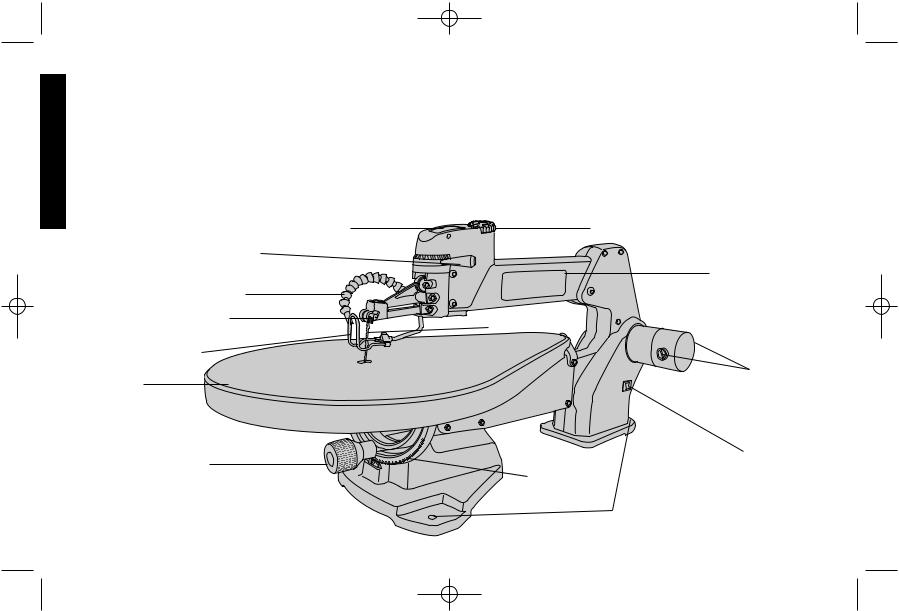
ON/OFF SWITCH |
SPEED CONTROL KNOB |
BLADE TENSION LEVER
UPPER ARM
AIR HOSE |
|
BLADE CLAMP |
|
THUMBSCREW |
BLADE |
MATERIAL HOLD-DOWN
BRUSH
TABLE  INSPECTION CAPS
BEVEL LOCK KNOB |
|
FUSE REPLACEMENT |
|
BEVEL SCALE |
CAP |
||
|
|||
|
|
||
|
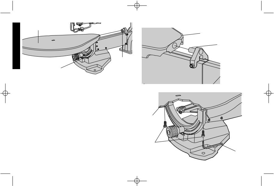
MOUNTING HOLES (3) |
|

DW788/383329 8/6/02 10:35 AM Page 1
 WARNING: For your own safety read instruction manual before operating tool.
Grounding Instructions
In the event of a malfunction or breakdown, grounding provides a path of least resistance for electric current to reduce the risk of electric shock. This tool is equipped with an electric cord having an equipment-grounding conductor and grounding plug. The plug must be plugged into a matching outlet that is properly installed and grounded in accordance with all local codes and ordinances. Do not modify plug provided—if it will not fit the outlet, have the proper outlet installed by a qualified electrician.
Improper connection of the equipment-grounding conductor can result in a risk of electric shock. The conductor with insulation having an outer surface that is green with or without yellow stripes is the equipment-grounding conductor. If repair or replacement of the electric cord or plug is necessary, do not connect the equipmentgrounding conductor to a live terminal.
Check with a qualified electrician or service personnel if the grounding instructions are not completely understood, or if in doubt as to whether the tool is properly grounded.
Use only 3-wire extension cords that have 3-prong grounding plugs and 3-pole receptacles that accept the tool’s plug.
Repair or replace damaged or worn cords immediately.
A GROUNDED B C
OUTLET |
GROUNDING |
|
BOX |
||
MEANS |
||
|
||
GROUNDING PIN |
ADAPTER |
|
|
This tool is intended for use on a circuit that has an outlet that looks like the one illustrated in Figure A. The tool has a grounding plug that looks like the plug illustrated in Figure A. A temporary adapter, which looks the adapter illustrated in Figures B and C, may be used to connect this plug to a 2-pole receptacle as shown in Figure B if a properly grounded outlet is not available. The temporary adapter should be used only until a properly grounded outlet can be installed by a qualified electrician. The green-colored rigid ear, lug, and the like, extending from the adapter must be connected to a permanent ground such as a properly grounded outlet box.
Important Safety Instructions
•KEEP GUARDS IN PLACE and in working order.
•KEEP WORK AREA CLEAN. Cluttered areas and benches invite injuries.
•DON’T USE IN DANGEROUS ENVIRONMENT. Don’t use power tools in damp or wet locations, or expose them to rain. Keep work area well lighted.
•KEEP CHILDREN AWAY. All visitors should be kept safe distance from work area.
•MAKE WORKSHOP KID PROOF with padlocks, master switches, or by removing starter keys.
•DON’T FORCE TOOL. It will do the job better and safer at the rate for which it was designed.
•USE RIGHT TOOL. Don’t force tool or attachment to do a job for which it was not designed.
•USE PROPER EXTENSION CORD. Make sure your extension cord is in good condition. When using and extension cord, be sure to use one heavy enough to carry the current your product will draw. An undersized cord will cause a drop in line voltage resulting in loss of power and overheating. The following table shows the correct size to use depending on cord length and nameplate ampere rating. If in doubt, use the next heavier gage. The smaller the gage number, the heavier the cord.
English
1

DW788/383329 8/6/02 10:35 AM Page 2
English
•OUTDOOR USE EXTENSION CORDS. When tool is used outdoors, use only extension cords intended for use outdoors and so marked.
|
|
|
Minimum Gage for Cord Sets |
|
||
Volts |
|
Total Length of Cord in Feet |
|
|
||
120V |
|
0-25 |
26-50 |
51-100 |
101-150 |
|
240V |
|
0-50 |
51-100 |
101-200 |
201-300 |
|
Ampere Rating |
AWG |
|
|
|
||
More |
Not more |
|
|
|
||
Than |
Than |
|
|
|
|
|
0 |
- |
6 |
18 |
16 |
16 |
14 |
6 |
- |
10 |
18 |
16 |
14 |
12 |
10 |
- |
12 |
16 |
16 |
14 |
12 |
12 |
- |
16 |
14 |
12 |
Not Recommended |
|
•WEAR PROPER APPAREL. Do not wear loose clothing, gloves, neckties, rings, bracelets, or other jewelry which may get caught in moving parts. Nonslip footwear is recommended. Wear protective hair covering to contain long hair.
•ALWAYS USE SAFETY GLASSES. Also use face or dust mask it cutting operation is dusty. Everyday eyeglasses only have impact resistant lenses, they are NOT safety glasses.
•DON’T OVERREACH. Keep proper footing and balance at all times.
•MAINTAIN TOOLS WITH CARE. Keep tools sharp and clean for best and safest performance. Follow instructions for changing accessories.
•DISCONNECT TOOLS before servicing; when changing accessories, such as blades, bits, cutters, and the like.
•REDUCE THE RISK OF UNINTENTIONAL STARTING. Make sure switch is in off position before plugging in.
•USE RECOMMENDED ACCESSORIES. Consult the instruction manual for recommended accessories. The use of improper accessories may cause risk of injury to persons.
•NEVER STAND ON TOOL. Serious injury could occur if the tool is tipped or if the cutting tool is unintentionally contacted.
•CHECK DAMAGED PARTS. Before further use of the tool, a guard
or other part that is damaged should be carefully checked to determine that it will operate properly and perform its intended function–check for alignment of moving parts, binding of moving parts, breakage of parts, mounting, and any other conditions that may affect its operation. A guard or other part that is damaged should be properly repaired or replaced.
•NEVER LEAVE TOOL RUNNING UNATTENDED. TURN POWER OFF. Don’t leave tool until it comes to a complete stop.
Additional Safety Rules for Scroll Saws
•MATERIAL HOLD-DOWN must be properly set according to these instructions and remain in position during use.
•NEVER reach under the table when operating or make any adjustments when it is running.
•SECURE saw to work bench or stand with clamps or mounting hardware. Secure work bench or stand to floor.
•DO NOT use the upper arm as a lifting point.
•MAKE SURE blade tension is properly adjusted.
•AVOID awkward hand positions where a sudden slip could cause a hand to move into a saw blade or cutting tool. DO NOT PLACE FINGERS OR HANDS IN PATH OF THE SAW BLADE.
•WHEN REMOVING short workpieces, or cleaning up around the table, be sure the saw is in the OFF position and blade has stopped moving.
•NEVER turn the saw ON before clearing the table of all tools, wood scraps, etc., except the workpiece and related feed or support devices for the operation planned.
•CHECK for proper blade size and type.
•DO NOT attempt to saw stock that does not have a flat surface, unless a suitable support is used.
•HOLD material firmly against table and feed into blade teeth at a moderate speed.
•TURN OFF motor if the material resists being backed out of an uncompleted cut. Use appropriate speed for applications.
•MAKE “relief” cuts before cutting long curves.
2

DW788/383329 8/6/02 10:35 AM Page 3
• CAUTION: Some wood contains preservatives such as copper chromium arsenate (CCA) which can be toxic. When cutting these materials, extra care should be taken to avoid inhalation and to minimize skin contact.
•USE a dust mask and safety glasses when sawing.
•KEEP GUARDS in place and working order.
•MAKE SURE your fingers do not contact the terminals of the power cord when installing or removing the plug to or from the line power source.
•NEVER overfeed or force work into the blade.
• WARNING: Do not allow familiarity (gained from frequent use of your saw) to replace following safety rules. Always remember that a careless fraction of a second is sufficient to inflict severe injury.
 WARNING: Some dust created by power sanding, sawing, grinding, drilling, and other construction activities contains chemicals known to cause cancer, birth defects or other reproductive harm. Some examples of these chemicals are:
•lead from lead-based paints,
•crystalline silica from bricks and cement and other masonry products, and
•arsenic and chromium from chemically-treated lumber (CCA).
Your risk from these exposures varies, depending on how often you do this type of work. To reduce your exposure to these chemicals: work in a well ventilated area, and work with approved safety equipment, such as those dust masks that are specially designed to filter out microscopic particles.
SAVE THESE INSTRUCTIONS
Mounting
Three holes are provided in the base of the scroll saw to facilitate mounting to a table or bench (Figure 1). Always mount your saw firmly to prevent movement.
FIG. 1
English
MOUNTING
HOLES
Assembly
Your scroll saw comes fully assembled except for the table and blade. To install the table, first insert the pin at the back of the arm into the hole in the back of the table (Figure 2). Push the table until its back surface is flush against the arm and the pin is fully inserted in the table (Figure 3).
Using the hex wrench packed with your scroll saw, securely attach the table to the bevel scale by tightening the bolts shown in Figure 4.
Installing the Blade
BEFORE INSTALLING A BLADE, UNPLUG THE SCROLL SAW.
The blade is held in place by the thumbscrew blade clamps attached to the top and bottom arms of the scroll saw (Figure 5).
Before installing a blade, make sure the blade tension lever is moved fully to the right as shown in Figure 6. Next, loosen, but do not unscrew, the top and bottom thumbscrews (Figure 5). Thread the blade through the hole in table, with the teeth facing toward the front of the saw. NOTE: Scroll saws cut on the downstroke, so it is essential that teeth face forward and down.
Insert the blade into the bottom blade clamp and securely tighten
3
DW788/383329 8/6/02 10:35 AM Page 4
TABLE |
FIG. 2 |
|
English
PIN
BEVEL SCALE
the thumbscrew. Next, insert the top of the blade into the top blade clamp and securely tighten the top thumbscrew.
Properly adjust the tension of the blade before operating your scroll saw. (See: Blade Tension Lever section of this manual.)
Blade Tension Lever
Move the blade tension lever (Figure 6) to the left to increase tension on the blade.
The proper degree of tension varies with different blade sizes. If you are frequently breaking blades, decrease tension on the blade.
As you become more accustomed to operating your scroll saw, you will become more proficient in fine-tuning blade tension. Practice on scrap material when possible.
Remove the blade or release tension on the blade when not using your scroll saw for an extended period.
Material Hold-down
The material hold-down (Figure 7) should contact the surface of the
FIG. 3
BACK OF TABLE
PIN
FIG. 4
TABLE
BOLTS
HEX WRENCH
4
DW788/383329 8/6/02 10:35 AM Page 5
TOP
THUMBSCREW
FIG. 5
BOTTOM THUMBSCREW
BLADE TENSION
LEVER
FIG. 6
workpiece. To adjust the material hold-down, loosen the thumbscrew (Figure 7) and move the rod up or down. The material hold-down must be beveled when the table is beveled. To bevel the material hold-down, loosen the allen screw shown in Figure 7 and bevel the material hold-down until it is parallel to the table. Retighten the material hold-down before cutting.
NOTE: When cutting, ensure the material hold-down does not contact the bottom arm of the scroll saw. Your scroll saw has a maximum thickness capacity of 2". Do not cut material thicker than 2". NEVER remove the material hold-down since it also functions as a barrier between fingers and blade.
Air Hose
Your scroll saw features an adjustable air hose to keep your work area free from dust and debris. Be sure to position the air hose properly: it should blow saw dust away from the operator.
On/Off Switch
To turn the scroll saw on, press the front of the switch as shown in Figure 8.The saw locks on automatically. To turn the tool off, press the back of the switch. A hole is provided in the switch for insertion of a padlock to lock the saw off (Figure 8).
Speed Control Knob
Your scroll saw features a variable speed control, from 400 to 1,750 strokes per minute. To operate the variable speed feature, turn the speed control knob (Figure 8) with the saw running.
To increase the speed, turn the knob clockwise. The numbers on the speed control knob represent speed ranges. One is the minimum speed, 8 is the maximum speed.
Slower speeds are recommended for metals, plastics, harder woods and very thin materials.
English
5

DW788/383329 8/6/02 10:35 AM Page 6
FIG. 7
English
MATERIAL |
SPEED CONTROL KNOB |
HOLD-DOWN |
|
THUMBSCREW |
|
|
FIG. 8 |
ALLEN SCREW |
|
|
ON/OFF SWITCH |
PADLOCK HOLE
MATERIAL
HOLD-DOWN
Sawing
Hold material firmly against table. Always feed material toward the blade. Feed the workpiece fast enough to allow the blade to cut, but do not force material into the blade too quickly.
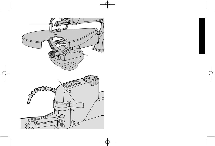
Beveling
The table of your scroll saw bevels 45° left and right. A detent is set at 0°. To bevel the scroll saw table, loosen the bevel lock knob (Figure 9), and bevel the table to the desired setting, indicated by the bevel pointer.
NOTE: Before tilting the table for bevel cuts of 45˚,check the clearance around the lower thumbscrew. To facilitate an accurate 45˚ cut the thumbscrew and setscrew may need to change places. On the setscrew side, sufficient clearance is available.
Fretwork
INSIDE CUTS
Your scroll saw is ideal for making inside cuts for detail work. To make an inside cut:
1.Drill a pilot hole in your workpiece.
2.Make sure the blade tension lever is moved fully to the right
3.Loosen the top thumbscrew blade clamp.
4.Leaving the blade held in place by the bottom blade clamp, lift the top arm of the scroll saw, as shown in Figure 10. Thread the saw blade through the pilot hole in your workpiece and reattach the blade by tightening the top thumbscrew.
5.Readjust the blade tension and begin the inside cut.
Alternately, you can loosen the bottom thumbscrew blade clamp in step 3 above, and thread the blade through the top of the workpiece.
6

DW788/383329 8/6/02 10:35 AM Page 7
FIG. 9
BEVEL LOCK KNOB
BEVEL POINTER |
BEVEL SCALE |
FIG. 10
FIG. 11
BRUSH
INSPECTION
CAPS
FUSE CAP
(PRESS TO RELEASE)
NOTE: Do not lift saw by upper arm. Damage will occur.
Overload Protector
Your scroll saw is equipped with a 3 amp overload protection fuse. If your scroll saw becomes overloaded and stops operating, turn off the scroll saw, check for a blown fuse by removing the fuse cap (Figure 11). Your scroll saw uses fuse #3AG Fast Acting, 1 1/4" long x 1/4" diameter.
Maintenance
BRUSHES
Inspect carbon brushes regularly by unplugging tool, removing the brush inspection cap (Figure 11) and withdrawing the brush assembly. Keep brushes clean and sliding freely in their guides. Always replace a used brush in the same orientation in the holder as it was prior to its removal. If the brush is worn down to 3/8", it must be replaced. Use only identical DEWALT brushes. New brush assemblies are available
English
7
 Loading...