


DW871/384765-01-00 2/10/00 10:07 AM Page 1

DW871/384765-01-00 2/10/00 10:07 AM Page 2
DEWALT Industrial Tool Company, P.O. Box 158, 626 Hanover Pike, Hampstead, MD 21074 |
Printed in China (JAN98-1) |
Form No. 384765-01 |
|
DW871 |
Copyright © 1998 |
|
|

DW871/384765-01-00 2/10/00 10:07 AM Page 3
INSTRUCTION MANUAL GUIDE D'UTILISATION MANUAL DE INSTRUCCIONES
INSTRUCTIVO DE OPERACIÓN, CENTROS DE SERVICIO Y PÓLIZA DE GARANTÍA.ADVERTENCIA: LÉASE ESTE INSTRUCTIVO ANTES DE USAR EL PRODUCTO.
DW871
14" (355 mm) Heavy Duty Chop Saw
Scie fendeuse de 355 mm (14 po) et de service intensif Cortadora de metales de 355 mm (14")
DW871/384765-01-00 2/10/00 10:07 AM Page 4
IF YOU HAVE ANY QUESTIONS OR COMMENTS ABOUT THIS OR ANY DEWALT TOOL, CALL US TOLL FREE AT:
1-800-4-DEWALT (1-800-433-9258)
English |
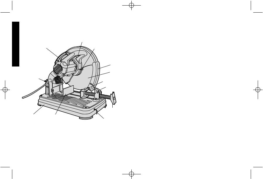
CARRY |
TRIGGER SWITCH |
|
||
|
WHEEL LOCK LEVER |
|
|
HANDLE |
|
|
|
WHEEL |
|
|
GUARD |
WHEEL
LOCK |
|
DOWN PIN |
VISE |
VISE LEVER
CRANK
BASE FENCE
HEX
WRENCH
 WARNING: FOR YOUR OWN SAFETY READ INSTRUCTION MANUAL BEFORE OPERATING CHOP SAW.
Important Safety Instructions
 WARNING! Read and understand all instructions. Failure to follow all instructions listed below may result in electric shock, fire and/or serious personal injury.
SAVE THESE INSTRUCTIONS•
•KEEP GUARDS IN PLACE and in working order.
•REMOVE ADJUSTING KEYS AND WRENCHES. Form habit of checking to see that keys and adjusting wrenches are removed from tool before turning it on.
•KEEP WORK AREA CLEAN. Cluttered areas and benches invite injuries.
•DON’T USE IN DANGEROUS ENVIRONMENT. Don’t use power tools in damp or wet locations, or expose them to rain. Keep work area well lighted.
•KEEP CHILDREN AWAY. All visitors should be kept at a safe distance from work area.
•MAKE WORKSHOP KID PROOF with padlocks, master switches, or by removing starter keys.
•DON’T FORCE TOOL. It will do the job better and safer at the rate for which it was designed.
•USE RIGHT TOOL. Don’t force tool or attachment to do a job for which it was not designed.
•USE PROPER EXTENSION CORD. Make sure your extension cord is in good condition. When using and extension cord, be sure to use one heavy enough to carry the current your product will draw. An undersized cord will cause a drop in line voltage resulting in loss of power and overheating. The following table shows the correct size to use depending on cord length and nameplate ampere rating. If in doubt, use the next heavier gage. The smaller the gage number, the heavier the cord.
1

DW871/384765-01-00 2/10/00 10:07 AM Page 5
|
|
|
Minimum Gage for Cord Sets |
|
||
Volts |
|
|
Total Length of Cord in Feet |
|||
120V |
0-25 |
26-50 |
51-100 |
101-150 |
|
|
240V |
0-50 |
51-100 |
101-200 |
201-300 |
|
|
Ampere Rating |
|
|
|
|
||
More |
Not more |
American Wire Gage |
|
|||
Than |
Than |
|
|
|
|
|
0 |
- |
6 |
18 |
16 |
16 |
14 |
6 |
- |
10 |
18 |
16 |
14 |
12 |
10 |
- |
12 |
16 |
16 |
14 |
12 |
12 |
- |
16 |
14 |
12 |
Not Recommended |
|
•WEAR PROPER APPAREL. Do not wear loose clothing, neckties, rings, bracelets, or other jewelry which may get caught in moving parts. Nonslip footwear is recommended. Wear protective hair covering to contain long hair.
•ALWAYS USE SAFETY GLASSES. Also use face or dust mask if cutting operation is dusty. Everyday eyeglasses only have impact resistant lenses, they are NOT safety glasses.
•SECURE WORK. Use clamps or a vise to hold work when practical. It’s safer than using your hand and it frees both hands to operate tool.
•DON’T OVERREACH. Keep proper footing and balance at all times.
•MAINTAIN TOOLS WITH CARE. Keep tools sharp and clean for best and safest performance. Follow instructions for lubricating and changing accessories.
•DISCONNECT TOOLS before servicing; when changing accessories, such as blades, bits, cutters, and the like.
•REDUCE THE RISK OF UNINTENTIONAL STARTING. Make sure switch is in off position before plugging in.
•USE RECOMMENDED ACCESSORIES. Consult the instruction manual for recommended accessories. The use of improper accessories may cause risk of injury to persons.
•NEVER STAND ON TOOL. Serious injury could occur if the tool is tipped or if the cutting tool is unintentionally contacted.
•CHECK DAMAGED PARTS. Before further use of the tool, a guard or other part that is damaged should be carefully checked to determine
that it will operate properly and perform its intended function — check |
|
for alignment of moving parts, binding of moving parts, breakage of |
2 |
|
parts, mounting, and any other conditions that may affect its operation. A guard or other part that is damaged should be properly repaired or replaced.
•DIRECTION OF FEED. Feed work into a blade or cutter against the direction of rotation of the blade or cutter only.
•NEVER LEAVE TOOL RUNNING UNATTENDED. TURN POWER OFF. Don’t leave tool until it comes to a complete stop.
•REPLACEMENT PARTS. When servicing use only identical replacement parts.
•TO REDUCE THE RISK OF ELECTRIC SHOCK, this equipment has a polarized plug (one blade is wider than the other.) This plug will fit in a polarized outlet only one way. If the plug does not fit, contact a qualified electrician to install the proper outlet. DO NOT CHANGE THE PLUG IN
ANY WAY.
Additional Safety Rules for Chop Saw
•Always wear safety goggles or other eye protection when using this tool.
•Before using, inspect each cutting wheel for cracks or flaws. If a crack or flaw is evident—discard the wheel! The wheel should also be inspected whenever you think the tool may have been dropped.
•When starting the tool (with a new or replacement wheel installed) place the tool in a well protected area. If the wheel has an undetected crack or flaw, it should burst in less than one minute. Never start the tool with a person in line with the wheel. This includes the operator.
•In operation, avoid bouncing the wheel or giving it rough treatment. If this occurs, stop the tool and inspect the wheel.
•Clean your chop saw periodically following the procedure in this manual.
•Do not remove wheel guard.
•Always use the vise or special fixturing to clamp work.
•Use only 14” type 1 wheels rated at 4100 rpm or higher.
•Allow cut off parts to cool before handling.
•Do not attempt to cut wood or plastic with this tool.
•NEVER CUT MAGNESIUM WITH THIS TOOL.
•Use chop saw in a well-ventilated area.
•Turn chop saw off before removing any pieces from the base.
•DO NOT CUT ELECTRICALLY LIVE MATERIAL.
English
DW871/384765-01-00 2/10/00 10:07 AM Page 6
English
•NEVER USE A CIRCULAR SAW BLADE IN THIS CHOP SAW. DO NOT USE TOOTHED BLADES.
•DO NOT OPERATE THIS TOOL NEAR FLAMMABLE LIQUIDS, GASES OR DUST. Sparks from cutting or motor may ignite dust and fumes.
Power Supply
Be sure your power supply agrees with the nameplate marking. 120 volts, “60 Hz” means alternating current (normal 120 volt, 60 Hz house current).
A voltage decrease of more than 10% will cause a loss of power and overheating.
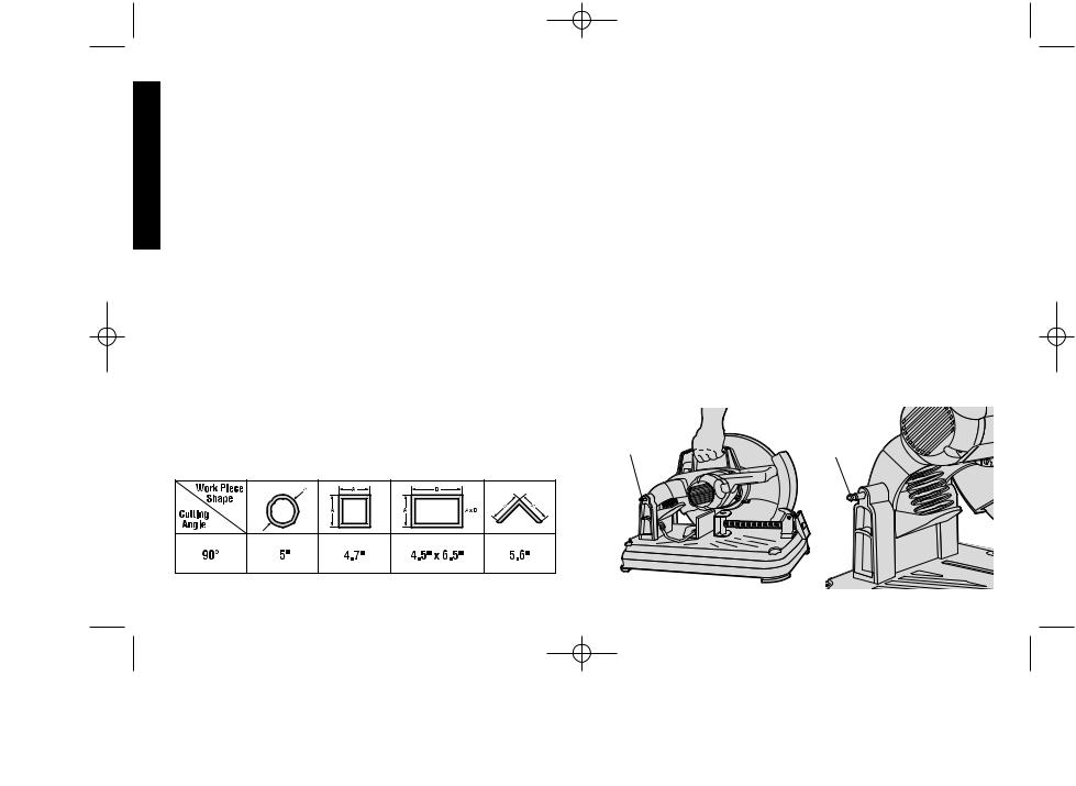
Cutting Capacity
The wide vise opening and high pivot point provide cutting capacity for many large pieces. Use the cutting capacity chart to determine total maximum size of cuts that can be made with a new wheel.
 CAUTION: CERTAIN LARGE, CIRCULAR OR IRREGULARLY SHAPED OBJECTS MAY REQUIRE ADDITIONAL HOLDING MEANS IF THEY CANNOT BE HELD SECURELY IN VISE.
 CAUTION: DO NOT CUT MAGNESIUM WITH THIS TOOL.
Maximum Cutting Capacity
NOTE: CAPACITY SHOWN ON CHART ASSUMES NO WHEEL WEAR AND OPTIMUM FENCE POSITION.
SAVE THESE INSTRUCTIONS
Standard Equipment
114” Metal Cutting Abrasive Wheel. Use only high strength Type 1 organic bonded wheels rated 4,100 rpm or higher.(Aluminum Oxide)
1 Wheel Wrench
To Carry
Fold down unit to position where you can carry the saw. Push in lock pin (Figure 1) to lock arm down.
Unlocking
To unlock tool and raise head, depress motor arm slightly and pull lock pin out. Motor arm will then pivot upward (see Figure 2).
Material Clamping and Supporting
•Angles are best clamped and cut with both legs resting against base
• A spacer block slightly narrower than the work space (see Figure 3) can be used to increase wheel utilization.
•Long workpieces must be supported by a block so it will be level with top of base (see Figure 4). The cut off end should be free
FIG. 1 |
FIG. 2 |
LOCK PIN |
LOCK PIN |
3

DW871/384765-01-00 2/10/00 10:07 AM Page 7
Spark Deflector Adjustment
To best deflect sparks away from surrounding persons and materials, loosen the screw, adjust the spark deflector and then retighten screw (see Figure 5).
Vise Operation
Vise has a quick travel feature. To release the vise when it is clamped tightly, turn the crank counterclockwise one or two times to remove clamping pressure. Lift vise lever up. Pull crank assembly out as far as desired. Vise may be shoved into work without cranking. Lower vise lever then tighten vise on work by using crank (see Figure 6).
DIAMETER OF |
|
|
|
WORK PIECE |
FENCE |
CUT OFF |
|
FIG. 3 |
|||
|
|||
|
END |
||
|
SPACER |
||
|
FIG. 4 |
||
|
BLOCK |
|
|
VISE |
|
|
|
WIDTH OF |
|
|
|
SPACER BLOCK |
|
|
SCREW
BLOCK
SPARK
DEFLECTOR
FIG. 5
Fence Operation
Fence requires no wrenches to adjust. The quick release clamp lever |
|
|
unlocks and locks the fence. When the lever is rotated fully forward, |
English |
|
the fence is unlocked. The fence can then be freely moved forward, |
||
|
backward or rotated to allow for the best cutting position for a new wheel and as the wheel wears.
Rotating the lever fully to the rear locks the fence in position selected. If the bottom leg of the lever is not horizontal (parallel to the base), the fence is not locked. Lever will only lock fence when there is strong resistance to moving it to rear. If resistance is light, adjust clamping force by tightening slightly the two bolts holding the fence to the base. Test by reclamping and attempt to move fence (see Figure 6).
FENCE |
FENCE |
|
|
FIG. 6 |
|
|
VISE |
||
BOLTS |
FORWARD |
|
||
VISE |
LEVER |
|
||
|
|
|||
|
|
|
|
|
|
|
|
|
CRANK |
CLAMP LEVER
4
DW871/384765-01-00 2/10/00 10:07 AM Page 8
Fence Angle Adjustment
|
Angle adjustment indicator is part of fence clamping system. Align |
|
English |
desired angle indicator line with edge of slot in base (see Figure 7). |
|
For a more accurate square cut (Figure 7), disconnect power supply, |
||
unlock fence, push arm down until wheel extends into base, place a |
||
|
||
|
square against wheel, adjust fence against square, then lock fence |
|
|
into position. |
|
|
Switch |
|
|
To start the tool, depress the trigger switch shown in Figure 8. To turn |
|
|
the tool off, release the trigger switch. Keep hands and material from |
|
|
wheel until it has coasted to a stop. |
FIG. 7
WHEEL
ANGLE ADJUSTMENT
INDICATOR
SQUARE
SLOT EDGE
FIG. 8
 TRIGGER SWITCH
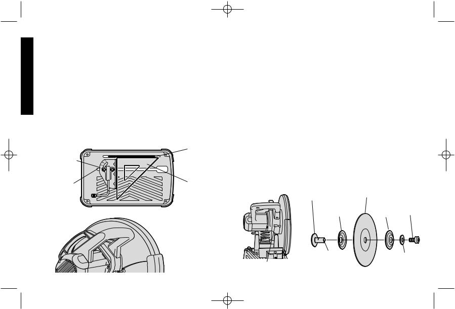
Removal and Installation of Wheels
1.Be sure tool is disconnected from power supply.
2.Push in wheel lock lever (Figure 9) and rotate wheel by hand until wheel lock lever engages slot in inside flange to lock wheel. Loosen the bolt counterclockwise in the center of the abrasive wheel with the 8 mm hex wrench found in the holder in the base. Bolt has right hand thread.
3.Remove the bolt, washer, outside flange, and old wheel (Fig. 10).
4.Install the new abrasive wheel by reversing the above steps.
5.Do not over tighten bolt.
DO NOT MAKE ANY ADJUSTMENT WHILE THE WHEEL IS IN MOTION. DO NOT MAKE ANY ADJUSTMENT WHILE CHOP SAW IS PLUGGED INTO POWER SUPPLY.
 WARNING: CHECK THE WORK SURFACE THAT THE CHOP SAW RESTS ON WHEN REPLACING WITH A NEW ABRASIVE WHEEL. IT IS POSSIBLE THAT THE WHEEL MAY CONTACT ANY ITEMS OR STRUCTURE THAT EXTENDS ABOVE WORK SURFACE (UNDER THE BASE) WHEN THE ARM IS FULLY LOWERED.
FIG. 9 |
SPINDLE SHAFT |
WHEEL |
FIG. 10 |
|
|
|
|||
|
FLANGE, |
FLANGE, |
M10 |
|
|
INSIDE |
OUTSIDE |
BOLT |
|
INTERNAL |
FLAT |
THREAD |
WASHER |
WHEEL LOCK LEVER
5
 Loading...