


DW400

DW400
4-1/2" Angle Grinder
Rectifieuse coudée de 115 mm (4-1/2 po)
Esmeriladora angular DW400 de 115 mm (4-1/2")
INSTRUCTION MANUAL
GUIDE D'UTILISATION
MANUAL DE INSTRUCCIONES
INSTRUCTIVO DE OPERACIÓN, CENTROS DE SERVICIO Y PÓLIZA
DE GARANTÍA. ADVERTENCIA: LÉASE ESTE INSTRUCTIVO
ANTES DE USAR EL PRODUCTO.
Questions? See us on the World Wide Web at www.dewalt.com


IF YOU HAVE ANY QUESTIONS OR COMMENTS ABOUT THIS
OR ANY D
EWALT TOOL, CALL US TOLL FREE AT:
1-800-4-D
EWALT (1-800-433-9258)
General Safety Instructions
WARNING! Read and understand all instructions.
Failure to follow all instructions listed below may result in
electric shock, fire and/or serious personal injury.
SAVE THESE INSTRUCTIONS
WORK AREA
• Keep your work area clean and well lit. Cluttered benches
and dark areas invite accidents.
• Do not operate power tools in explosive atmospheres, such
as in the presence of flammable liquids, gases, or dust.
Power tools create sparks which may ignite the dust or fumes.
• Keep bystanders, children, and visitors away while operating a power tool. Distractions can cause you to lose control.
ELECTRICAL SAFETY
• Grounded tools must be plugged into an outlet properly
installed and grounded in accordance with all codes and
ordinances. Never remove the grounding prong or modify
the plug in any way. Do not use any adapter plugs. Check
with a qualified electrician if you are in doubt as to whether
the outlet is properly grounded. If the tools should electrical-
ly malfunction or break down, grounding provides a low resistance path to carry electricity away from the user. Applicable
only to Class I (grounded) tools.
• Double insulated tools are equipped with a polarized plug
(one blade is wider than the other.) This plug will fit in a
polarized outlet only one way. If the plug does not fit fully in
the outlet, reverse the plug. If it still does not fit, contact a
qualified electrician to install a polarized outlet. Do not
change the plug in any way. Double insulation eliminates the
need for the three wire grounded power cord and grounded
power supply system. Applicable only to Class II (double
insulated) tools.
• Avoid body contact with grounded surfaces such as pipes,
radiators, ranges, and refrigerators. There is an increased
risk of electric shock if your body is grounded.
• Don’t expose power tools to rain or wet conditions. Water
entering a power tool will increase the risk of electric shock.
• Do not abuse the cord. Never use the cord to carry the tools
or pull the plug from an outlet. Keep cord away from heat,
oil, sharp edges or moving parts. Replace damaged cords
immediately. Damaged cords increase the risk of electric shock.
• When operating a power tool outside, use an outdoor extension cord marked “W-A” or “W.” These cords are rated for
outdoor use and reduce the risk of electric shock.
Minimum Gage for Cord Sets
Volts Total Length of Cord in Feet
120V 0-25 26-50 51-100 101-150
240V 0-50 51-100 101-200 201-300
Ampere Rating
More Not more AWG
Than Than
0-6 18 16 16 14
PERSONAL SAFETY
• Stay alert, watch what you are doing and use common
sense when operating a power tool. Do not use tool while
tired or under the influence of drugs, alcohol, or medication.
A moment of inattention while operating power tools may result
in serious personal injury.
• Dress properly. Do not wear loose clothing or jewelry.
Contain long hair. Keep your hair, clothing, and gloves
English
1

away from moving parts. Loose clothes, jewelry, or long hair
can be caught in moving parts. Air vents often cover moving
parts and should also be avoided.
• Avoid accidental starting. Be sure switch is off before plugging
in. Carrying tools with your finger on the switch or plugging in
tools that have the switch on invites accidents.
• Remove adjusting keys or wrenches before turning the tool
on. A wrench or a key that is left attached to a rotating part of
the tool may result in personal injury.
• Do not overreach. Keep proper footing and balance at all
times. Proper footing and balance enables better control of the
tool in unexpected situations.
• Use safety equipment. Always wear eye protection. Dust
mask, non-skid safety shoes, hard hat, or hearing protection
must be used for appropriate conditions.
TOOL USE AND CARE
• Use clamps or other practical way to secure and support
the workpiece to a stable platform. Holding the work by hand
or against your body is unstable and may lead to loss of control.
• Do not force tool. Use the correct tool for your application.
The correct tool will do the job better and safer at the rate for
which it is designed.
• Do not use tool if switch does not turn it on or off. Any tool
that cannot be controlled with the switch is dangerous and must
be repaired.
• Disconnect the plug from the power source before making
any adjustments, changing accessories, or storing the tool.
Such preventative safety measures reduce the risk of starting
the tool accidentally.
• Store idle tools out of reach of children and other untrained
persons. Tools are dangerous in the hands of untrained users.
• Maintain tools with care. Keep cutting tools sharp and
clean. Properly maintained tools, with sharp cutting edges are
less likely to bind and are easier to control.
• Check for misalignment or binding of moving parts, breakage of parts, and any other condition that may affect the
tools operation. If damaged, have the tool serviced before
using. Many accidents are caused by poorly maintained tools.
• Use only accessories that are recommended by the manufacturer for your model. Accessories that may be suitable for
one tool, may become hazardous when used on another tool.
SERVICE
• Tool service must be performed only by qualified repair
personnel. Service or maintenance performed by unqualified
personnel could result in a risk of injury.
• When servicing a tool, use only identical replacement parts.
Follow instructions in the Maintenance section of this manual. Use of unauthorized parts or failure to follow maintenance
instructions may create a risk of electric shock or injury.
Additional Specific Safety Instructions
for Grinders
• Always use proper guard with grinding wheel. A guard protects operator from broken wheel fragments and wheel contact.
• Accessories must be rated for at least the speed recommended on the tool warning label. Wheels and other
accessories running over rated speed can fly apart and cause
injury. Accessory ratings must always be above tool speed as
shown on tool nameplate.
• Hold tool by insulated gripping surfaces when performing
an operation where the cutting tool may contact hidden
wiring or its own cord. Contact with a “live” wire will make
exposed metal parts of the tool “live” and shock the operator.
English
2

• Do not use Type 11 (flaring cup) wheels on this tool. Using
inappropriate accessories can result in injury.
• Before using, inspect recommended accessory for cracks
or flaws. If such a crack or flaw is evident, discard the
accessory. The accessory should also be inspected whenever you think the tool may have been dropped. Flaws may
cause wheel breakage.
• When starting the tool with a new or replacement wheel, or
a new or replacement wire brush installed, hold the tool in
a well protected area and let it run for one minute. If the
wheel has an undetected crack or flaw, it should burst in less
than one minute. If the wire brush has loose wires, they will be
detected. Never start the tool with a person in line with the
wheel. This includes the operator.
• Avoid bouncing the wheel or giving it rough treatment. If this
occurs, stop the tool and inspect the wheel for cracks or flaws.
• Direct sparks away from operator, bystanders or flammable
materials. Sparks may be produced while using a sander or
grinder. Sparks may cause burns or start fires.
• Always use side handle. Tighten the handle securely. The
side handle should always be used to maintain control of the tool
at all times.
• Clean out your tool often, especially after heavy use. Dust
and grit containing metal particles often accumulate on interior
surfaces and could create an electric shock hazard.
CAUTION: Type 1 Abrasive and Diamond Cut-Off Wheels may
not be used on this tool. A Type 1 Cut-Off Wheel Guard is not available for the DW400.
• The label on your tool may include the following symbols.
V ..............volts A............amperes
Hz ............hertz W ..........watts
min ..........minutes ..........alternating current
........direct current
n
o ..........no load speed
..............
Class II Construction ..........safety alert symbol
..............
earthing terminal
.../min ....revolutions or
.................. ..............per minute
CAUTION: Use extra care when grinding into a corner as a
sudden, sharp movement of the grinder may be experienced
when the wheel contacts a secondary surface.
CAUTION: Wear appropriate personal hearing protection
during use. Under some conditions and duration of use, noise
from this product may contribute to hearing loss.
WARNING: Some dust created by power sanding, sawing,
grinding, drilling, and other construction activities contains chemicals known to cause cancer, birth defects, or other reproductive
harm. Some examples of these chemicals are:
• lead from lead-based paints,
• crystalline silica from bricks and cement and other masonry
products, and
• arsenic and chromium from chemically-treated lumber
(CCA).
Your risk from these exposures varies, depending on how often you
do this type of work. To reduce your exposure to these chemicals:
work in a well ventilated area, and work with approved safety equipment, such as those dust masks that are specially designed to
filter out microscopic particles.
• Avoid prolonged contact with dust from power sanding,
sawing, grinding, drilling, and other construction
activities. Wear protective clothing and wash exposed
areas with soap and water. Allowing dust to get into your
mouth, eyes, or lay on the skin may promote absorption of
harmful chemicals.
English
3
WARNING: Use of this tool can generate and/or disburse dust,
which may cause serious and permanent respiratory or other injury.
Always use NIOSH/OSHA approved respiratory protection appropriate for the dust exposure. Direct particles away from face and
body.
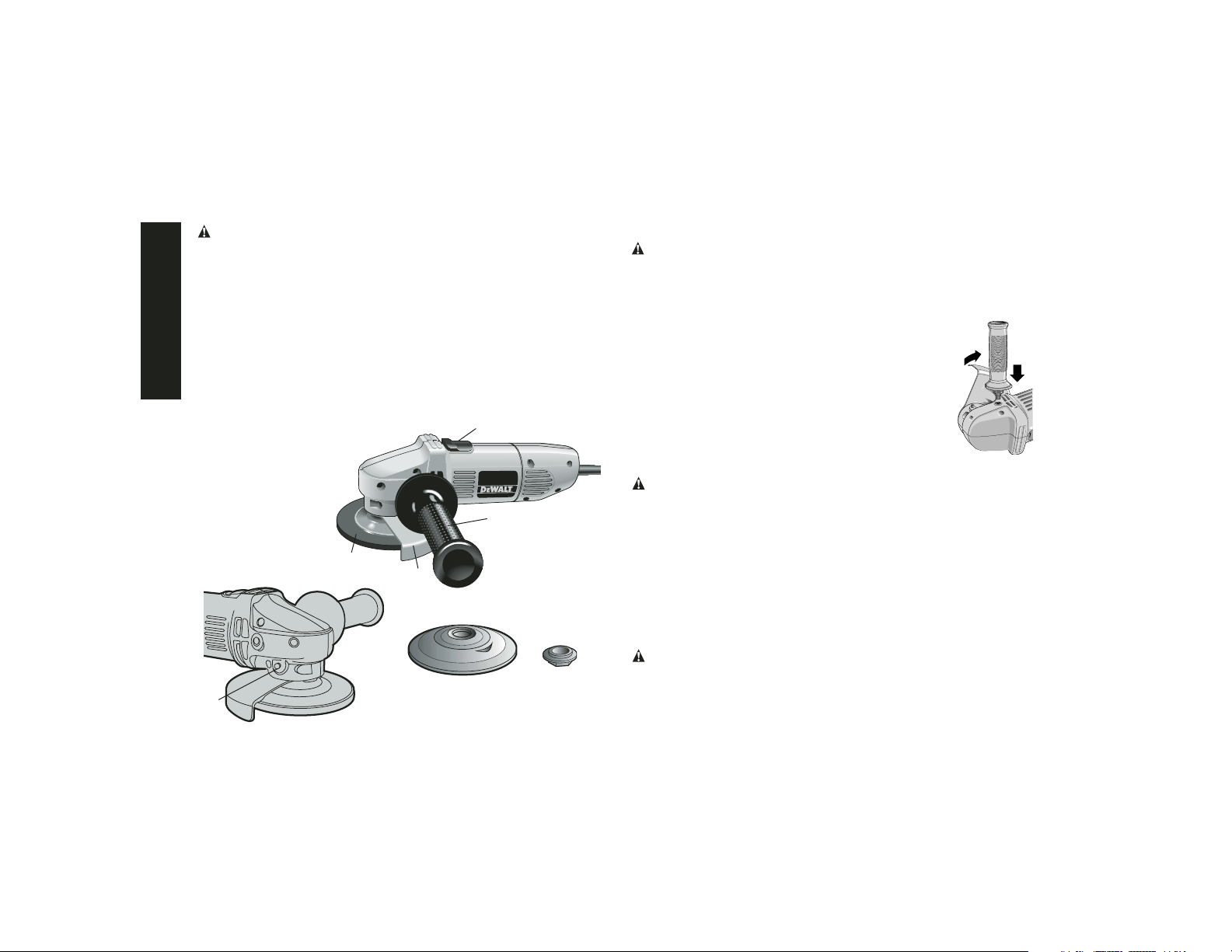
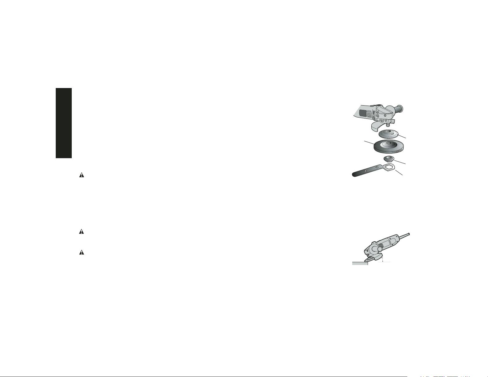
COMPONENTS
A. Switch E. Spindle Lock Pin
B. Guard F. Unthreaded Backing Flange
C. Wheel G. Threaded Clamp Nut
D. Side Handle
ASSEMBLY AND ADJUSTMENTS
CAUTION: Turn off and unplug the tool before making any
adjustments or removing or installing attachments or accessories. Before reconnecting the tool, depress and release the
rear part of the switch to ensure that the tool is off.
ATTACHING SIDE HANDLE
The side handle can be fitted to either side of the gear
case in the threaded holes, as shown. Before using
the tool, check that the handle is tightened securely.
ACCESSORIES
It is important to choose the correct guards, backing
pads and flanges to use with grinder accessories.
See pages 5–6 for information on choosing the correct accessories. A Type 1 Cut-Off Wheel Guard is
not available for the DW400.
CAUTION: Accessories must be rated for at least the speed
recommended on the tool warning label. Wheels and other accessories running over their rated speed may fly apart and cause
injury. Threaded accessories must have a 5/8" – 11 hub. Every
unthreaded accessory must have a 7/8" arbor hole. If it does not, it
may have been designed for a circular saw. Use only the accessories shown on pages 5–6 of this manual. Accessory ratings must
always be above tool speed as shown on tool nameplate.
OPERATION
STARTING AND STOPPING THE TOOL
CAUTION: Before connecting the tool to a power supply, be sure
the switch is in the OFF position by pressing the rear part of the
switch and releasing. If the switch is locked on when the power is
connected, the tool will start unexpectedly.
D
C
A
F
G
B
E
English
4
R
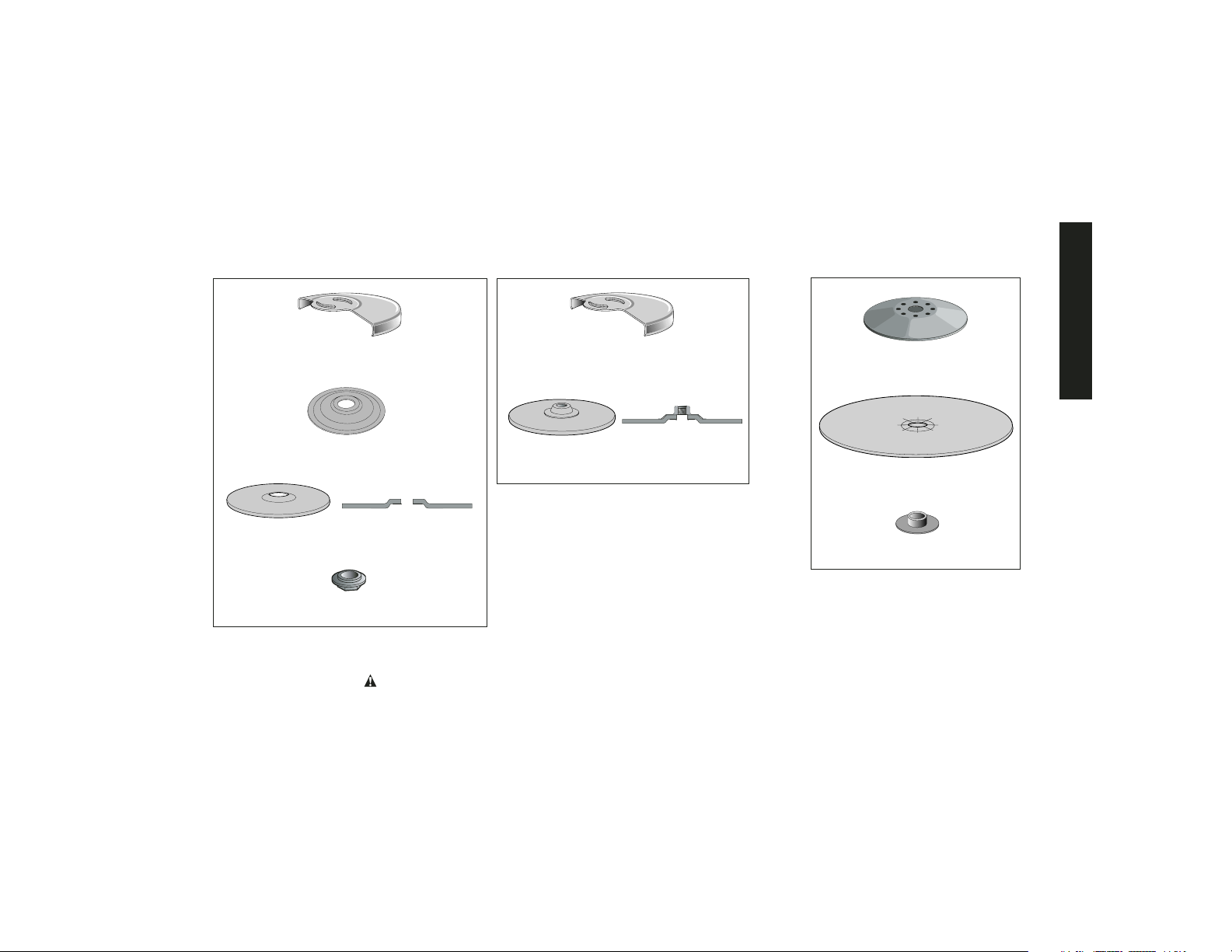
Type 27 guard
Type 27 depressed center wheel
4 1/2" Grinding Wheels
metal unthreaded backing flange
threaded clamp nut
rubber backing pad
sanding disc
threaded clamp nut
Sanding Discs
Type 27 guard
Type 27 hubbed wheel
CAUTION: Type 1 Abrasive and Diamond Cut-Off Wheels may not be used on
this tool. A Type 1 Cut-Off Wheel Guard is not available for the DW400.
English
5
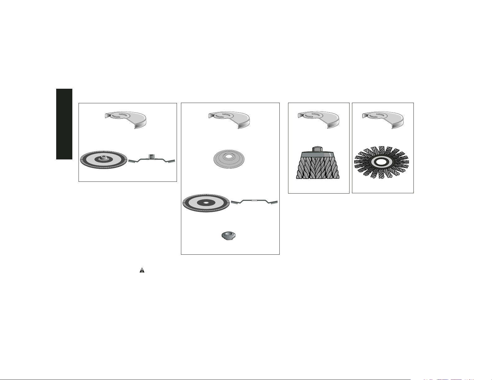
Wire Wheels
3" wire cup brush
4 1/2" Sanding Flap Discs
Type 27 guard
hubbed sanding flap disc
Type 27 guard
metal unthreaded
backing flange
non-hubbed sanding flap disc
threaded clamp nut
Type 27 guard
4" wire wheel
Type 27 guard
CAUTION: Type 1 Abrasive and Diamond Cut-Off Wheels may not be used on this tool.
A Type 1 Cut-Off Wheel Guard is not available for the DW400.
English
6
1. To start the tool, slide the ON/OFF
switch (A) toward the front of the tool.
2. To stop the tool, release the ON/OFF
switch.
3. For continuous operation, slide the
switch toward the front of the tool and
press the forward part of the switch
inward.
4. To stop the tool while operating in continuous mode, press the
rear part of the switch and release.
NOTE: To reduce unexpected tool movement, do not switch the
tool on or off while under load conditions.
CAUTION: Hold the side handle and body of the tool firmly to
maintain control of the tool at start up and during use and until the
wheel or accessory stops rotating. Make sure the wheel has come
to a complete stop before laying the tool down.
CAUTION: Allow the tool to reach full speed before touching
tool to the work surface. Lift the tool from the work surface before
turning the tool off.
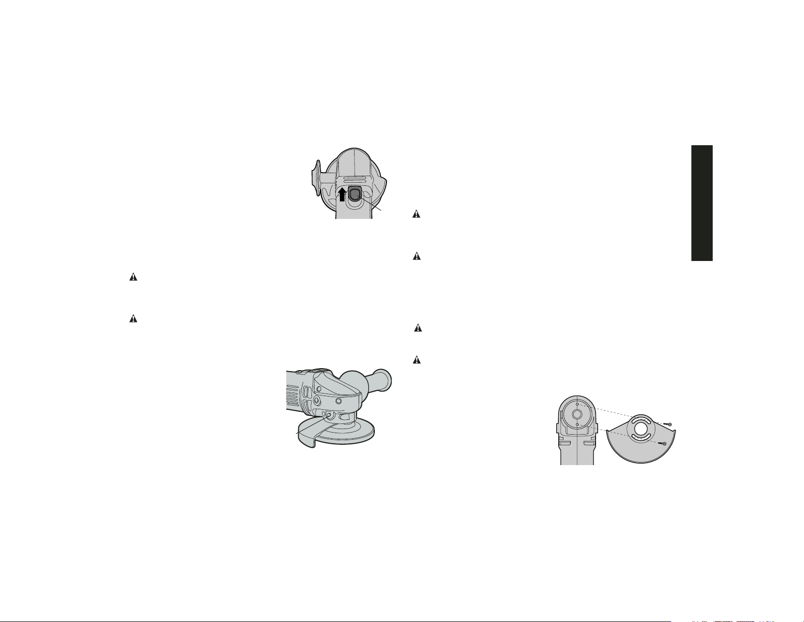
Spindle Lock
The spindle lock pin (E) is provided to
prevent the spindle from rotating when
installing or removing wheels. Operate
the spindle lock pin only when the tool
is turned off and unplugged from the
power supply. Do not engage the
spindle lock while the tool is operating
because damage to the tool will result
and attached accessory may spin off
possibly resulting in injury.
To engage the lock, depress the spindle lock button (E) and
rotate the spindle until you are unable to rotate the spindle further.
Mounting and Using Depressed Center
Grinding Wheels and Sanding Flap Discs
MOUNTING AND REMOVING GUARD
CAUTION: Turn off and unplug the tool before making any
adjustments or removing or installing attachments or accessories. Before reconnecting the tool, actuate and release
switch to ensure that the tool is off.
CAUTION: Guards must be used with all grinding wheels, sand-
ing flap discs, wire brushes, and wire wheels. The tool may be used
without a guard only when sanding with conventional sanding
discs. D
E
WALT model DW400 is provided with a guard intended for
use with depressed center wheels (Type 27) and hubbed grinding
wheels (Type 27). The same guard is designed for use with sanding
flap discs (Type 27 and 29) and wire cup brushes and wire wheels.
CAUTION: Type 1 Abrasive and Diamond Cut-Off Wheels may
not be used on this tool. A Type 1 Cut-Off Wheel Guard is not available for the DW400.
CAUTION: Proper guard must be re-installed for grinding wheel
applications after sanding applications are complete.
1. Align the openings on the guard with the holes on the grinder,
as shown.
2. With guard skirt facing away
from grinder, rotate the guard
into desired working position.
The guard should be positioned between the spindle
and the operator to provide
maximum operator protection.
E
A
English
7
1. Be sure the guard assembly is securely attached to the gear
case.
2. Put the backing flange (F) onto the
tool spindle as shown.
3. Check rated speed on depressed
center wheel. Never use wheel with
rated speed lower than the recommended accessory speed on the
nameplate of the tool.
4. Place the depressed center wheel
(H) on the tool spindle as shown.
5. Thread the threaded clamp nut (G)
on tool spindle as shown. Hold the
tool spindle by engaging the spindle
lock pin, and tighten clamp washer
with wrench (I).
SURFACE GRINDING WITH GRINDING WHEELS
Using Type 27 Wheels:
1. Allow the tool to reach full speed before touching the tool to the
work surface.
2. Apply minimum pressure to the work surface, allowing the tool
to operate at high speed. Grinding rate is greatest when the tool
operates at high speed.
3. Maintain a 20˚ to 30˚ angle between
the tool and work surface.
4. Continuously move the tool in a
forward and back motion to avoid
creating gouges in the work surface.
5. Remove the tool from work surface before turning tool off. Allow
the tool to stop rotating before laying it down.
You may locate the guard to any convenient angle as long as
the guard skirt is located between the operator and the accessory. Insert and tighten screws to secure guard in place. You
should not be able to rotate guard by hand.
3. To rotate the guard, loosen the screws clamping the guard to
the tool and rotate as desired. Tighten screws to secure the
guard in place.
4. To remove the guard, loosen and remove screws.
NOTE: Edge grinding and cutting can be performed with Type 27
wheels designed and specified for this purpose; 1/4" thick wheels
are designed for surface grinding while 1/8" wheels are designed
for edge grinding.
MOUNTING AND REMOVING HUBBED WHEELS
CAUTION: Turn off and unplug the tool before making any
adjustments or removing or installing attachments or accessories. Before reconnecting the tool, actuate and release
switch to ensure that the tool is off.
Hubbed wheels install directly on the 5/8" – 11 threaded spindle.
1. Thread the wheel on the spindle by hand.
2. Depress the spindle lock button and use a wrench to tighten the
hub of the wheel.
3. Reverse the above procedure to remove the wheel.
CAUTION: Failure to properly seat the wheel before turning the
tool on may result in damage to the tool or the wheel.
MOUNTING NON-HUBBED WHEELS
CAUTION: Turn off and unplug the tool before making any
adjustments or removing or installing attachments or accessories. Before reconnecting the tool, actuate and release
switch to ensure that the tool is off.
Depressed center, Type 27 grinding wheels must be used with
included flanges. See page 5–6 of this manual for more information.
F
H
G
I
20˚-30˚
English
8
EDGE GRINDING WITH GRINDING WHEELS
WARNING: Edge grinding and cutting can be performed only with
Type 27 wheels that are designed and specified for this purpose.
WARNING: Wheels used for cutting and edge grinding may
break or kick back if they bend or twist while the tool is being used
to do cut-off work or deep grinding. To reduce the risk of serious
injury, limit the use of these wheels with a standard Type 27 guard
to shallow cutting and notching (less than 1/2" in depth). The open
side of the guard must be positioned away from the operator.
1. Allow the tool to reach full speed before touching the tool to the
work surface.
2. Apply minimum pressure to the work
surface, allowing the tool to operate at
high speed. Grinding rate is greatest
when the tool operates at high speed.
3. Position yourself so that the open-underside of the wheel is facing away from
you.
4. Once a cut is begun and a notch is
established in the workpiece, do not
change the angle of the cut. Changing
the angle will cause the wheel to bend
and may cause wheel breakage.
5. Remove the tool from the work surface
before turning the tool off. Allow the tool
to stop rotating before laying it down.
WARNING: Do not use edge grinding/cutting wheels for surface
grinding applications because these wheels are not designed for
side pressures encountered with surface grinding. Wheel breakage
and injury may result.
SURFACE FINISHING WITH SANDING FLAP DISCS
1. Allow the tool to reach full speed before touching the tool to the
work surface.
2. Apply minimum pressure to work surface, allowing the tool to
operate at high speed. Sanding rate is greatest when the tool
operates at high speed.
3. Maintain a 5˚ to 10˚ angle between
the tool and work surface.
4. Continuously move the tool in a
forward and back motion to avoid
creating gouges in the work surface.
5. Remove the tool from work surface before turning tool off. Allow
the tool to stop rotating before laying it down.
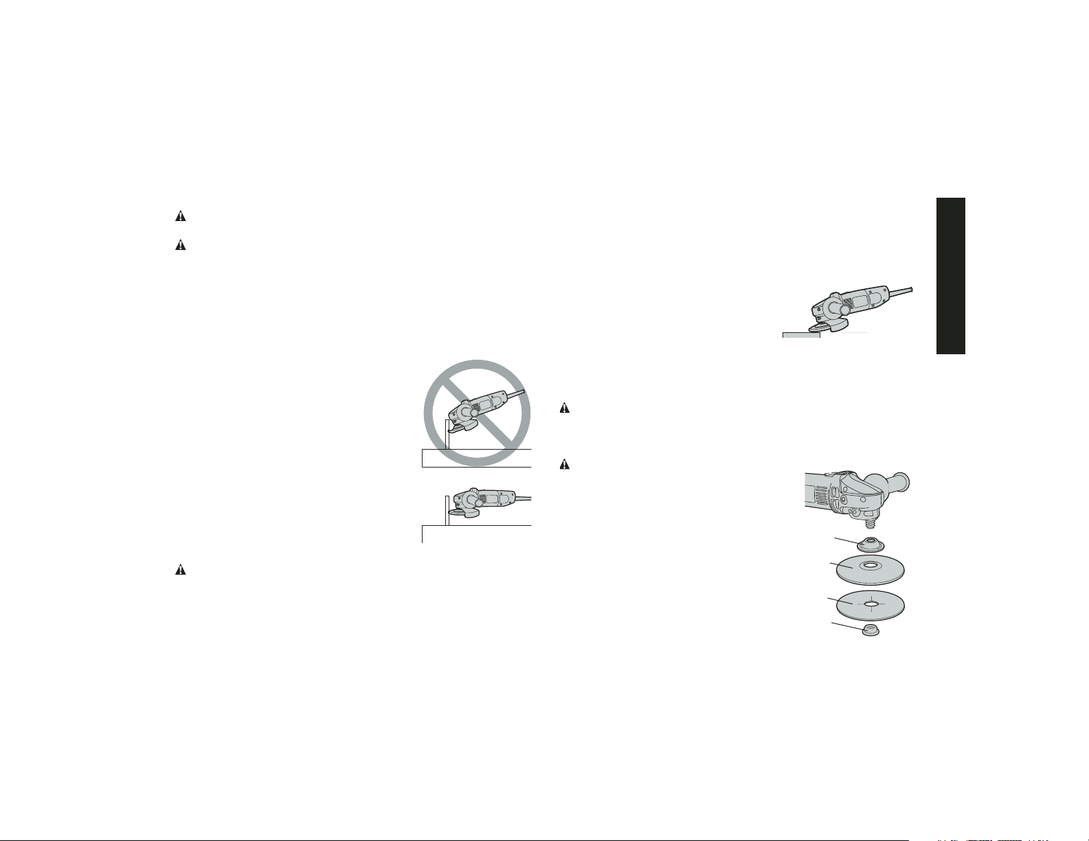
MOUNTING SANDING BACKING PADS
CAUTION: Turn off and unplug the tool before making any
adjustments or removing or installing attachments or accessories. Before reconnecting the tool, actuate and release
switch to ensure that the tool is off.
CAUTION: The proper guard must be re-
installed for the grinding wheel, sanding flap
disc, wire brush or wire wheel applications
after sanding applications are complete.
1. Push the hub of the disc nut (M) through
the center of the sanding disc (L), as far
as it will go, and also through the backing
disc (K).
2. Assemble the disc nut hub (J), backing
pad, sanding disc, and disc nut as
shown.
3. Be sure the disc nut extends through the
discs into the disc nut hub.
5˚-10˚
J
K
L
M
English
9

4. Move the tool constantly in a straight line to prevent burning and
swirling of work surface. Allowing the tool to rest on the work
surface without moving, or moving the tool in a circular motion
causes burning and swirling marks on the work surface.
5. Remove the tool from work surface before turning tool off. Allow
the tool to stop rotating before laying it down.
Precautions To Take When Sanding Paint
1. Sanding of lead based paint is NOT RECOMMENDED due to
the difficulty of controlling the contaminated dust. The greatest
danger of lead poisoning is to children and pregnant women.
2. Since it is difficult to identify whether or not a paint contains lead
without a chemical analysis, we recommend the following precautions when sanding any paint:
PERSONAL SAFETY
1. No children or pregnant women should enter the work area
where the paint sanding is being done until all clean up is completed.
2. A dust mask or respirator should be worn by all persons entering the work area. The filter should be replaced daily or whenever the wearer has difficulty breathing.
NOTE: Only those dust masks suitable for working with lead
paint dust and fumes should be used. Ordinary painting masks
do not offer this protection. See your local hardware dealer for
the proper N.I.O.S.H. approved mask.
3. NO EATING, DRINKING or SMOKING should be done in the
work area to prevent ingesting contaminated paint particles.
Workers should wash and clean up BEFORE eating, drinking or
smoking. Articles of food, drink, or smoking should not be left in
the work area where dust would settle on them.
4. Thread the assembled parts (clockwise) completely down on
the spindle.
5. Depress the spindle lock button while turning the sanding disc
until the sanding disc and clamp nut are snug.
6. To remove the wheel, grasp and turn the backing pad and
sanding disc while depressing the spindle lock button.
USING SANDING BACKING PADS
Choose the proper grit sanding disc for your application. Sanding
discs are available in various grits. Coarse grits yield faster material
removal rates and a rougher finish. Finer grits yield slower material
removal and a smoother finish.
Begin with lower grit discs for fast, rough material removal. Move to
a medium grit paper and finish with a fine grit disc for optimal finish.
Coarse 16 - 30 grit
Medium 36 - 80 grit
Fine Finishing 100 - 120 grit
Very Fine Finishing 150 - 180 grit
1. Allow the tool to reach full speed before touching tool to the
work surface.
2. Apply minimum pressure to work surface, allowing the tool to
operate at high speed. Sanding rate is greatest when the tool
operates at high speed.
3. Maintain a 5˚ to 15˚ angle between the
tool and work surface. The sanding
disc should contact approximately one
inch of work surface. The lower angle
will produce a smoother surface.
Using only the outer edge at a higher angle will produce an
irregular and bumpy finish. However, if the disc is used flat on
the surface, the tool will be difficult to control.
5˚-15˚
English
10

ENVIRONMENTAL SAFETY
1. Paint should be removed in such a manner as to minimize the
amount of dust generated.
2. Areas where paint removal is occurring should be sealed with
plastic sheeting of 4 mils thickness.
3. Sanding should be done in a manner to reduce tracking of paint
dust outside the work area.
CLEANING AND DISPOSAL
1. All surfaces in the work area should be vacuumed and thoroughly cleaned daily for the duration of the sanding project.
Vacuum filter bags should be changed frequently.
2. Plastic drop cloths should be gathered up and disposed of
along with any dust chips or other removal debris. They should
be placed in sealed refuse receptacles and disposed of through
regular trash pick-up procedures.
During clean up, children and pregnant women should be kept
away from the immediate work area.
3. All toys, washable furniture and utensils used by children
should be washed thoroughly before being used again.
Mounting and Using Wire Brushes
and Wire Wheels
Wire cup brushes or wire wheels screw directly on the grinder
spindle without the use of flanges. Use only wire brushes or
wheels provided with a 5/8" – 11 threaded hub. A Type 27 guard is
required when using wire brushes and wheels.
CAUTION: Wear work gloves when handling wire brushes. Wire
brushes can become sharp.
MOUNTING WIRE BRUSHES AND WIRE WHEELS
CAUTION: Turn off and unplug the tool before making any
adjustments or removing or installing attachments or acces-
sories. Before reconnecting the tool, actuate and release
switch to ensure that the tool is off.
1. Thread the wheel on the spindle by hand.
2. Depress spindle lock button and use a wrench on the hub of
the wire wheel or brush to tighten the wheel.
3. To remove the wheel, reverse the above procedure.
CAUTION: Failure to properly seat the wheel hub before turning
the tool on may result in damage to tool or wheel.
USING WIRE BRUSHES AND WIRE WHEELS
Wire wheels and brushes can be used for removing rust, scale and
paint, and for smoothing irregular surfaces.
NOTE: The same precautions should be taken when wire brushng
paint as when sanding paint (see page 10).
1. Allow the tool to reach full speed before touching the tool to the
work surface.
2. Apply minimum pressure to work surface, allowing the tool to
operate at high speed. Material removal rate is greatest when
the tool operates at high speed.
3. Maintain a 5˚ to 10˚ angle between
the tool and work surface for wire cup
brushes.
4. Maintain contact between the edge of
the wheel and the work surface with
wire wheels.
5. Continuously move the tool in a forward
and back motion to avoid creating
gouges in the work surface. Allowing the
tool to rest on the work surface without
moving, or moving the tool in a circular
motion causes burning and swirling
marks on the work surface.
5˚-10˚
English
11

Purchasing Accessories
Recommended accessories for use with your tool are available at
extra cost from your local dealer or authorized service center.
If you need assistance in locating any accessory for your tool,
contact: D
EWALT Industrial Tool Co., 701 East Joppa Road,
Baltimore, MD 21286.
CAUTION: The use of any other accessory not recommended
for use with this tool could be hazardous.
Three Year Limited Warranty
DEWALT will repair, without charge, any defects due to faulty materials or workmanship for three years from the date of purchase.
This warranty does not cover part failure due to normal wear or tool
abuse. For further detail of warranty coverage and warranty repair
information, visit www.dewalt.com or call 1-800-4-D
EWALT (1-800-
433-9258). This warranty does not apply to accessories or damage
caused where repairs have been made or attempted by others.
This warranty gives you specific legal rights and you may have
other rights which vary in certain states or provinces.
In addition to the warranty, D
EWALT tools are covered by our:
1 YEAR FREE SERVICE
D
EWALT will maintain the tool and replace worn parts caused by
normal use, for free, any time during the first year after purchase.
90 DAY MONEY BACK GUARANTEE
If you are not completely satisfied with the performance of your
D
EWALT Power Tool, Laser, or Nailer for any reason, you can
return it within 90 days from the date of purchase with a receipt for
a full refund – no questions asked.
FREE WARNING LABEL REPLACEMENT: If your warning labels
become illegible or are missing, call 1-800-4-D
EWALT for a free
replacement.
6. Remove the tool from the work surface before turning the tool
off. Allow the tool to stop rotating before setting it down.
MAINTENANCE
Cleaning
WARNING: Blow dust and grit out of the motor housing regularly
using clean, dry compressed air. Dust and grit containing metal
particles often accumulate on interior surfaces and could create an
electrical shock hazard if not frequently cleaned out. ALWAYS
WEAR SAFETY GLASSES.
CAUTION: Never use solvents or other harsh chemicals
for cleaning the non-metallic parts of the tool. These chemicals
may weaken the plastic materials used in these parts. Use a
clean, dry cloth only.
Lubrication
DEWALT tools are properly lubricated at the factory and are ready
for use. Tools should be relubricated regularly every sixty days to six
months, depending on usage. (Tools used constantly on production
or heavy-duty jobs and tools exposed to heat may require more
frequent lubrication.) This lubrication should only be attempted by
trained power tool repair persons, such as those at D
EWALT serv-
ice centers or by other qualified service personnel.
Motor Brushes
When brushes become worn, the tool will automatically stop and
prevent damage to the motor. Brush replacement should be performed by D
EWALT authorized service centers.
Repairs
To assure product SAFETY and RELIABILITY, repairs, maintenance and adjustments should be performed by authorized service
centers or other qualified service personnel. Always use identical
replacement parts.
English
12
 Loading...