


If you have questions or comments, contact us. Pour toute question ou tout commentaire, nous contacter.
Si tiene dudas o comentarios, contáctenos.
1-800-4-DEWALT • www.dewalt.com
INSTRUCTION MANUAL
GUIDE D’UTILISATION MANUAL DE INSTRUCCIONES
INSTRUCTIVO DE OPERACIÓN, CENTROS DE SERVICIO Y PÓLIZA DE GARANTÍA. ADVERTENCIA: LÉASE ESTE INSTRUCTIVO ANTES DE USAR EL PRODUCTO.
DW756
6" (152 mm) Heavy-Duty Bench Grinder, Meuleuse d'établi de 152 mm (6 po) de service intensif, Esmeriladora de banco de 152 mm (6")
DW758
8" (200 mm) Heavy-Duty Bench Grinder, Meuleuse d'établi de 200 mm (8 po) de service intensif, Esmeriladora de banco de 200 mm (8") para trabajo pesado

Definitions: Safety Guidelines
The definitions below describe the level of severity for each signal word. Please read the manual and pay attention to these symbols.
 DANGER: Indicates an imminently hazardous situation which, if not avoided, will result in death or serious injury.
  WARNING: Indicates a potentially hazardous situation which, if not avoided, could result in death or serious injury.
 CAUTION: Indicates a potentially hazardous situation which, if not avoided, may result in minor or moderate injury. NOTICE: Indicates a practice not related to personal injury which, if not avoided, may result in property damage.
IF YOU HAVE ANY QUESTIONS OR COMMENTS ABOUT THIS OR ANY DEWALT TOOL, CALL US TOLL FREE AT: 1-800-4-DEWALT (1-800-433-9258).
 WARNING: To reduce the risk of injury, read the instruction manual.
Important Safety Instructions
WARNING! Read all safety warnings and all instructions.
Failure to follow the warnings and instructions may result in electric shock, fire and/or serious injury.
READ ALL INSTRUCTIONS
Grounding Instructions
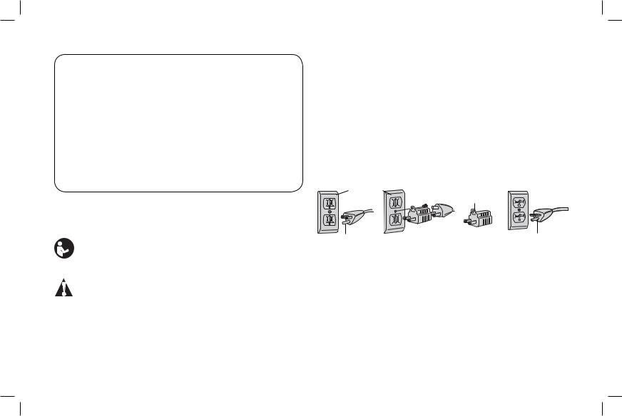
This tool should be grounded while in use to protect the operator from electric shock. The tool is equipped with a 3-conductor cord
1
and 3-prong grounding type plug to fit the proper grounding type receptacle. The green (or green and yellow) conductor in the cord is the grounding wire. Never connect the green (or green and yellow) wire to a live terminal. If your unit is intended for use on less than 150 V, it has a plug that looks like that shown in sketch A. If it is for use on 150 to 250 V, it has a plug that looks like that shown in sketch D. An adapter, sketches B and C, is available for connecting sketch A type plugs to 2-prong receptacles. The green-colored rigid ear, lug, or the like, extending from the adapter must be connected to a permanent ground, such as a properly grounded outlet box. No adapter is available for a plug as shown in sketch D. ADAPTER SHOWN IN FIGURES B and C IS NOT FOR USE IN CANADA.
A GROUNDED B |
C |
D |
|
OUTLET |
GROUNDING |
||
BOX |
|||
MEANS |
|
||
|
|
||
GROUNDING PIN |
ADAPTER |
GROUNDING PIN |
|
|
|||
Safety Instructions For All Tools
•KEEP WORK AREA CLEAN. Cluttered areas and benches invite injuries.
•CONSIDER WORK AREA ENVIRONMENT. Don’t expose power tools to rain. Don’t use power tools in damp or wet locations. Keep work area well lit. Do not use tool in presence of flammable liquids or gases.
•GUARD AGAINST ELECTRIC SHOCK. Prevent body contact with grounded surfaces. For example; pipes, radiators, ranges, and refrigerator enclosures.

English
•KEEP CHILDREN AWAY. Do not let visitors contact tool or extension cord. All visitors should be kept away from work area.
•STORE IDLE TOOLS. When not in use, tools should be stored in dry, and high or locked-up place — out of reach of children.
•DON’T FORCE TOOL. It will do the job better and safer at the rate for which it was intended.
•USE RIGHT TOOL. Don’t force small tool or attachment to do the job of a heavy-duty tool. Don’t use tool for purpose not intended.
•DRESS PROPERLY. Do not wear loose clothing or jewelry. They can be caught in moving parts. Rubber gloves and nonskid footwear are recommended when working outdoors. Wear protective hair covering to contain long hair.
•USE SAFETY GLASSES. Also use face or dust mask if operation is dusty.
•DON’T ABUSE CORD. Never carry tool by cord or yank it to disconnect from receptacle. Keep cord from heat, oil, and sharp edges.
•SECURE WORK. Use clamps or a vise to hold work. It’s safer than using your hand and it frees both hands to operate tool.
•DON’T OVERREACH. Keep proper footing and balance at all times.
•MAINTAIN TOOLS WITH CARE. Keep tools sharp and clean for better and safer performance. Follow instructions for lubricating and changing accessories. Inspect tool cords periodically and if damaged, have repaired by authorized service facility. Inspect extension cords periodically and replace if damaged. Keep handles dry, clean, and free from oil and grease.
•DISCONNECT OR LOCK OFF TOOLS when not in use, before servicing, and when changing accessories, such as blades, bits, cutters.
•REMOVE ADJUSTING KEYS AND WRENCHES. Form habit of checking to see that keys and adjusting wrenches are removed from tool before turning it on.
•AVOID UNINTENTIONAL STARTING. Don’t carry tool with finger on switch. Be sure switch is off when plugging in.
•EXTENSION CORDS. Use only 3-wire extension cords that have 3-prong grounding-type plugs and 3-pole receptacles that accept the tool’s plug. Replace or repair damaged cords. Make sure your extension cord is in good condition. When using an extension cord, be sure to use one heavy enough to carry the current your product will draw. An undersized cord will cause a drop in line voltage resulting in loss of power and overheating. The following table shows the correct size to use depending on cord length and nameplate ampere rating. If in doubt, use the next heavier gage. The smaller the gage number, the heavier the cord.
Minimum Gauge for Cord Sets
Ampere |
Volts |
Total Length of Cord in Feet (meters) |
|||||
120V |
25 (7.6) |
50 (15.2) |
|
100 (30.5) |
150 (45.7) |
||
Rating |
|
||||||
240V |
50 (15.2) |
100 (30.5) |
|
200 (61.0) |
300 (91.4) |
||
|
|
|
|||||
More |
Not |
|
|
|
|
|
|
Than |
More |
|
|
AWG |
|
|
|
|
Than |
|
|
|
|
|
|
0 |
6 |
|
18 |
16 |
|
16 |
14 |
6 |
10 |
|
18 |
16 |
|
14 |
12 |
10 |
12 |
|
16 |
16 |
|
14 |
12 |
12 |
16 |
|
14 |
12 |
|
Not Recommended |
|
•OUTDOOR USE EXTENSION CORDS. When tool is used outdoors, use only extension cords intended for use outdoors and so marked.
•STAY ALERT. Watch what you are doing. Use common sense. Do not operate tool when you are tired.
•CHECK DAMAGED PARTS. Before further use of the tool, a guard or other part that is damaged should be carefully checked to determine that it will operate properly and perform its intended
2

function. Check for alignment of moving parts, binding of moving parts, breakage of parts, mounting, and any other conditions that may affect its operation. A guard or other part that is damaged should be properly repaired or replaced by an authorized service center unless otherwise indicated elsewhere in this instruction manual. Have defective switches replaced by authorized service center. Do not use tool if switch does not turn it on and off.
•KEEP GUARDS IN PLACE and in working order.
•USE RECOMMENDED ACCESSORIES. Consult the owner's manual for recommended accessories. The use of improper accessories may cause risk of injury to persons.
•NEVER STAND ON TOOL. Serious injury could occur if the tool is tipped or if the cutting tool is unintentionally contacted.
Additional Safety Instructions for Grinders
•ALWAYS USE GUARDS AND EYE SHIELDS. WHEN GRINDING, ALWAYS KEEP GUARDS IN PLACE.
•Use only grinding wheels having a maximum operating speed at least as high as the “No Load RPM” marked on the tool’s nameplate. Use only grinding wheels suitable for the speed of the grinder.
•Use only flanges furnished with the grinder.
•Adjust distance between wheel and work rest to maintain 1/8" (3.18 mm) or less separation as the diameter of the wheel decreases with use.
•Before using, inspect recommended accessory for cracks or flaws. If such a crack or flaw is evident, discard the accessory. DO NOT USE A GRINDING WHEEL THAT IS CRACKED OR FLAWED IN ANY WAY.
•When starting the tool, let it run for one minute. Never start the tool with a person in line with the wheel. This includes the operator.
3
•Do not grind on the sides of grinding wheels unless they are specifically designed for that purpose.
•Do not overtighten the hex nut. This may crack the grinding wheel.
•Clean the cavity around the grinding wheel periodically.
 WARNING: ALWAYS use safety glasses. Everyday eyeglasses are NOT safety glasses. Also use face or dust mask if cutting operation is dusty. ALWAYS WEAR CERTIFIED SAFETY EQUIPMENT:
•ANSI Z87.1 eye protection (CAN/CSA Z94.3),
•ANSI S12.6 (S3.19) hearing protection,
•NIOSH/OSHA/MSHA respiratory protection.
 WARNING: Some dust created by power sanding, sawing, grinding, drilling, and other construction activities contains chemicals known to the State of California to cause cancer, birth defects or other reproductive harm. Some examples of these chemicals are:
•lead from lead-based paints,
•crystalline silica from bricks and cement and other masonry products, and
•arsenic and chromium from chemically-treated lumber.
Your risk from these exposures varies, depending on how often you do this type of work. To reduce your exposure to these chemicals: work in a well ventilated area, and work with approved safety equipment, such as those dust masks that are specially designed to filter out microscopic particles.
•Avoid prolonged contact with dust from power sanding, sawing, grinding, drilling, and other construction activities. Wear protective clothing and wash exposed areas with soap and water. Allowing dust to get into your mouth, eyes, or lay on the skin may promote absorption of harmful chemicals.
 WARNING: Use of this tool can generate and/or disperse dust, which may cause serious and permanent respiratory or other
English
English
injury. Always use NIOSH/OSHA approved respiratory protection appropriate for the dust exposure. Direct particles away from face and body.
 WARNING: Always wear proper personal hearing protection that conforms to ANSI S12.6 (S3.19) during use. Under some conditions and duration of use, noise from this product may contribute to hearing loss.
•The label on your tool may include the following symbols. The symbols and their definitions are as follows:
V................... |
volts |
A...................... |
|
amperes |
|||||||
Hz................. |
hertz |
W..................... |
|
watts |
|||||||
min ............... |
minutes |
|
|
|
or AC.......... |
alternating |
|||||
|
|
|
|
|
or DC |
direct current |
|
|
|
|
current |
|
|
|
|
|
|
|
|
|
|||
|
|
|
|
|
|
Class I Construction |
|
|
|
or AC/DC |
alternating |
|
|
|
|
................. |
|
|
|
|
|||
..................... |
|
|
|
|
|
(grounded) |
........................ |
|
|
|
or direct |
|
|
|
|
................. |
|
Class II Construction |
no |
|
current |
||
|
|
|
|
|
|
(double insulated) |
.................... |
no load |
|||
…/min .......... |
per minute |
|
|
|
|
speed |
|||||
BPM ............. |
beats per minute |
n ...................... |
|
rated |
|||||||
IPM............... |
impacts per minute |
........................ |
|
|
|
speed |
|||||
RPM |
revolutions per |
|
|
|
|
earthing |
|||||
|
|
|
|
||||||||
|
|
..................... |
|
||||||||
|
|
|
|
|
|
minute |
|
|
|
|
terminal |
sfpm ............. |
surface feet |
|
|
..................... |
|
safety alert |
|||||
..................... |
|
|
|
|
|
per minute |
|
|
|
|
symbol |
SPM ............. |
strokes per minute |
|
|
|
|
|
|||||
SAVE THESE INSTRUCTIONS
FOR FUTURE USE
Motor
Be sure your power supply agrees with the nameplate marking. Voltage decrease of more than 10% will cause loss of power and overheating. DEWALT tools are factory tested; if this tool does not operate, check power supply.
COMPONENTS (Fig. 1)
 WARNING: Never modify the power tool or any part of it. Damage or personal injury could result.
A. Spark guards |
D. Tool rests |
B. Eye shields |
E. Switch (On/Off) |
C. Coarse grinding |
F. Medium grinding |
wheel (36 Grit) |
wheel (60 Grit) |
FIG. 1 |
A |
|
|
|
B |
C
D
F
E
4

Model |
Bench Grinder |
Arbor |
RPM |
DW756 |
6" (152 mm) |
1/2" (13 mm) |
3450 |
DW758 |
8" (200 mm) |
5/8" (16 mm) |
3600 |
ASSEMBLY AND ADJUSTMENTS
 WARNING: To reduce the risk of injury, turn unit off and disconnect it from power source before installing and removing accessories, before adjusting or when making repairs. An accidental start-up can cause injury.
Bench Mounting
1.The grinder should be unplugged.
2.Remove the drilling template from this manual (page 36) and place it in position of the bench. Check for the availability of power for the grinder. Tape the template to the bench.
3.Using a center punch, transfer the hole centers for drilling.
4.Drill appropriate sized holes.
5.Insert M8 hex head bolts through washers and the holes. You may want to use washers on the underside of the bench as well.
6.Tighten the nuts. Do not overtighten. Allow the rubber feet to absorb the vibration when the grinder is running.
Installing Tool Rests (Fig. 2)
There is a left and right tool rest. First secure the tool rest (D) to the bracket (G) using the hex bolt (H), spring washer (I), flat washer (J), external tooth washer (K) and nut (M).
For the DW756, an additional spacer (L) and external tooth washer (K) are required, as shown in Figure 2.
5
Next, for the DW756 and the DW758, secure the bracket/tool rest assembly to the wheel guard (BB) using the two 1/4"-20UNC bolts (N), and two flat washers (J).
Proceed to install the other tool rest using the same description.
 CAUTION: Longer bolts may interfere with the movement of the grinding wheel.
NOTE: When in use, the tool rests should be adjusted to within 1/8" (3.18 mm) of the grinding wheel or other accessory being used.
FIG. 2
BB
|
J |
|
|
|
N |
|
|
|
D |
M |
|
|
|
||
I |
J |
G |
|
K |
K |
||
H |
|||
|
L |
||
|
|
||
|
|
DW756 ONLY |
English

English
Installing Spark Guards (Fig. 3)
The spark guards (A) are identified L for left and R for right. Refer to Figure 3 to install the spark guard to the wheel guard (BB) using the two bolts (O) and flat washers (J). Adjust the edge of the spark guard to within 1/16" (1.6 mm) of the grinding wheel or other accessory. Tighten the two bolts (O) securely.
Proceed to install the other spark guard using the same description.
Installing Eye Shields (Fig. 4)
 WARNING: Eye shields are not designed to replace safety glasses.
Install the eye shields (B) (they will fit either side) to the brackets, as shown in Figure 4. Screw the plastic knob (P) through the washer (Q), the spark guard (A), the spacer (R), the eye shield (B) and finally into the nut (S). Adjust eye shields so they are between the wheels and your eyes.
Proceed to install the other eye shield using the same description. Tighten the shields in place by tightening the plastic knob (P) in the bracket assembly. Remove protective film.
FIG. 3 |
|
FIG. 4 |
|
O |
J |
Q A R |
B S |
P |
|
||
|
|
A |
|
|
|
BB |
|
OPERATION
 WARNING: To reduce the risk of injury, turn unit off and disconnect it from power source before installing and removing accessories, before adjusting or when making repairs. An accidental start-up can cause injury.
 CAUTION: Prolonged grinding will cause most materials to become hot. Handle them with pliers or thick gloves.
 CAUTION: Never attempt to use your bench grinder unless it is firmly bolted to a workbench or rigid frame that is also firmly attached to the floor.
•Before turning the grinder on, put on safety glasses.
•Turn on the grinder and allow it to reach full speed (3450 RPM - DW756, 3600 RPM - DW758).
•Hold the workpiece firmly and against the tool rest.
•Hold very small pieces with pliers or other suitable clamps.
•Feed the work smoothly and evenly into the grinding wheel.
•Move the work slowly and avoid jamming the work against the wheel. As the wheel tends to slow down you should occasionally release the pressure to let the wheel return to full speed.
•Grind only on the face of the grinding wheel and never on the side. (Some wheels are designed for side grinding and will say so on their instruction sheets).
Switch (Fig. 1)
The switch (E) is located on the front of the grinder, on the base.
To turn the tool on depress the side of the rocker switch on the left side, marked “ON”.
To turn off the grinder, depress the right side of the rocker switch, marked “OFF”.
6

MAINTENANCE
 WARNING: To reduce the risk of injury, turn unit off and disconnect it from power source before installing and removing accessories, before adjusting or when making repairs. An accidental start-up can cause injury.
Cleaning
 WARNING: Blow dirt and dust out of all air vents with clean, dry air at least once a week. To minimize the risk of eye injury, always wear ANSI Z87.1 approved eye protection when performing this.
 WARNING: Never use solvents or other harsh chemicals for cleaning the non-metallic parts of the tool. These chemicals may weaken the plastic materials used in these parts. Use a cloth dampened only with water and mild soap. Never let any liquid get inside the tool; never immerse any part of the tool into a liquid.
Accessories
 WARNING: Since accessories, other than those offered by DEWALT, have not been tested with this product, use of such accessories with this tool could be hazardous. To reduce the risk of injury, only DEWALT recommended accessories should be used with this product.
Grinding wheels must fit within the confines of the guard and must be rated higher than the recommended speed as marked on the bench grinder nameplate.
Recommended accessories for use with your tool are available at extra cost from your local dealer or authorized service center. If you need assistance in locating any accessory, please contact DEWALT Industrial Tool Co., 701 East Joppa Road, Towson, MD 21286, call 1-800-4-DEWALT (1-800-433-9258) or visit our website: www. dewalt.com.
7
 WARNING: To reduce the risk of injury, always use proper guards when grinding and wear eye protection.
 CAUTION: Strands of wire cup brushes may break and fly off while in use. Users and others in the area should wear adequate eye, face and body protection. Use only wire cup brushes that are rated at or greater than the RPM shown on the tool’s nameplate.
 CAUTION: The use of any non-recommended accessory may be hazardous.
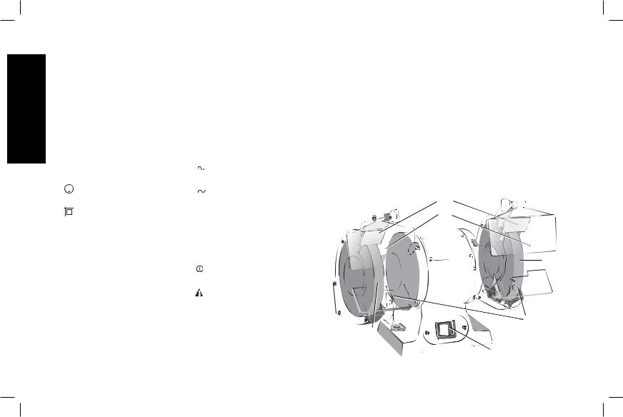
Changing Accessories (Fig. 2, 5, 6, 7)
Change accessories when the spark guard can no longer be adjusted to 1/16" (1.6 mm) from the wheel.
DW756 - use only wheels that measure 6" (152 mm) in diameter. This tool has 1/2" (13 mm) arbors on each side.
DW758 - use only wheels that measure 8" (200 mm) in diameter. This tool has 5/8" (16 mm) arbors on each side. Follow the steps below to remove and replace an accessory.
1.Raise the eye shield (B).
2.Loosen, but do not remove, the tool rest bolts (H, Fig. 2) and pull the tool rest (D) out as far as possible. Do not remove it.
3.Loosen, but do not remove, the spark guard bolts (O,
FIG. 5
B
TA
U
T
D
English

English
Fig. 3) and pull the spark guard (A) out as far as possible. Do not remove it.
4.Remove the screws (T) from both side covers (U) and remove the covers.
5.Using hex or adjustable wrenches, grasp the two hex nuts (V) holding the wheels to the arbor shaft (W) at each end of the tool (Refer to Fig. 6, 7). To remove the wheel from the left side, turn the hex nut (V) clockwise while holding the other stationary. To remove the wheel from the right side, turn the hex nut (V) counter clockwise while holding the other stationary.
6.Remove the wheel flanges (X) and the wheel (Y).
7.Inspect the wheel for cracks, chips or any other visible damage
(other than normal wear) and discard if such damage is found. Inspect the blotter (Z) for damage. If the blotter is missing or severely damaged, replace it with a piece of thin cardboard or blotter paper cut to the same size. NEVER USE A WHEEL WITHOUT A BLOTTER.
FIG. 6
W |
DW756 |
Z |
|
|
X
V
X
Y
8
FIG. 7
ZX
X |
DW758 |
V 


 W
W
AA
YS
8.Install the new wheel or other accessory (Y).
For the DW756 (Fig. 6), be sure that the wheel flanges (X) are in place (concave side toward the wheel).
For the DW758 (Fig. 7), be sure the spacers (AA) and the wheel flanges (X) are both in place (concave side toward the wheel).
9.Hold both hex nuts (V) as before and tighten them but do not overtighten. Overtightening can crack a grinding wheel.
10.Replace the wheel covers and their screws.
11.Adjust the spark guard (A) to 1/16" (1.6 mm) from the wheel and tighten securely.
12.Adjust the tool rest (D) to 1/8" (3.18 mm) from the wheel and tighten securely.
13.Adjust the eye shield (B) to a point between your eyes and the wheel. The bench grinder is now ready for use.
14.Follow the above steps to install buffing wheels and wire wheel brushes as well as grinding wheels.
Repairs
To assure product SAFETY and RELIABILITY, repairs, maintenance and adjustment (including brush inspection and replacement) should be performed by a DEWALT factory service center, a DEWALT authorized service center or other qualified service personnel. Always use identical replacement parts.
Three Year Limited Warranty
DEWALT will repair, without charge, any defects due to faulty materials or workmanship for three years from the date of purchase. This warranty does not cover part failure due to normal wear or tool abuse. For further detail of warranty coverage and warranty repair information, visit www.dewalt.com or call 1-800-4-DEWALT (1-800- 433-9258). This warranty does not apply to accessories or damage caused where repairs have been made or attempted by others. This warranty gives you specific legal rights and you may have other rights which vary in certain states or provinces.
In addition to the warranty, DEWALT tools are covered by our:
1 YEAR FREE SERVICE
DEWALT will maintain the tool and replace worn parts caused by normal use, for free, any time during the first year after purchase.
30 DAY NO RISK SATISFACTION GUARANTEE
If you are not completely satisfied with the performance of your DEWALT heavy-duty industrial tool, simply return it to the participating seller within 30 days for a full refund. Please return the complete unit, transportation prepaid. Proof of purchase may be required.
LATIN AMERICA: This warranty does not apply to products sold in Latin America. For products sold in Latin America, see country specific warranty information contained in the packaging, call the local company or see website for warranty information.
9
FREE WARNING LABEL REPLACEMENT: If your warning labels become illegible or are missing, call 1-800-4-DEWALT (1-800-433- 9258) for a free replacement.
DW756
GRINDING WHEELS |
MAX. SAFE SPEED |
5/8" (16 mm) Face, 6" (152 mm) dia. 60 grit |
4136 RPM |
medium grinding wheel |
|
3/4" (19 mm) Face, 6" (152 mm) dia. 60 grit |
4136 RPM |
medium grinding wheel |
|
5/8" (16 mm) Face, 6" (152 mm) dia. 36 grit |
4136 RPM |
coarse grinding wheel |
|
1/2" (13 mm) Face, 6" (152 mm) dia. 60 grit |
3825 RPM |
medium grinding wheel |
|
BUFFING WHEELS |
|
5/8" (16 mm) Face, 6" (152 mm) dia. cotton |
3600 RPM |
buffing wheel |
|
English

English
WIRE WHEEL BRUSHES
1/2" (13 mm) arbor, 5/8" (16 mm) Face, |
3600 RPM |
6" (152 mm) dia. |
|
DW758
GRINDING WHEELS |
MAX. SAFE SPEED |
7/8" (22 mm) & 1" (25 mm) Face, 8" (200 mm) |
3600 RPM |
dia. 60 grit medium grinding wheel |
|
7/8" (22 mm) & 1" (25 mm) Face, 8" (200 mm) |
3600 RPM |
dia. 36 grit coarse grinding wheel |
|
BUFFING WHEEL |
|
5/8" (16 mm) arbor, 8" dia. cotton buffing wheel |
3600 RPM |
WIRE WHEEL BRUSHES |
|
5/8" (16 mm) arbor, 5/8" (16 mm)–1-1/4" |
3600 RPM |
(32 mm) Face, 8" (200 mm) dia. |
|
10
 Loading...