


TD 3.6 L4

TD / TCD 3.6 L4
Operation Manual
EU Stage IV / US EPA Tier 4
OBJ_DOKU-44425-001.fm Seite 1 Donnerstag, 19. Februar 2015 2:46 14

Notes
2 © 2014
Notes
● This engine is defined exclusively for purpose
according to the scope of delivery and built by
the equipment manufacturer (use for the intend
-
ed purpose). Any other use above and beyond
this will be considered as misuse. The manufac
-
turer will not accept any liability for damages re
-
sulting from this. The user bears the sole risk.
● Use for the intended purpose also includes ob
-
servance of the operating, maintenance and re
-
pair conditions specified by the manufacturer.
The engine should only be operated, serviced
and repaired by personnel trained in its use and
the hazards involved.
The pertinent rules for the prevention of acci
-
dents and other generally recognised safety and
industrial medicine rules must be observed.
● When the engine is running there is a danger of
injury caused by:
– rotating and hot components
– on motors with external ignition (high electri
-
cal voltage). Contact must be avoided!
● Unauthorised engine modifications will invalidate
any liability claims against the manufacturer for
resultant damage.
● Equally, manipulations to the injection and con
-
trol system can affect the engine's performance
and the exhaust characteristics. Adherence to
legislation on pollution can no longer be guaran
-
teed under such conditions.
● Do not change the cooling air feed area to the
blower of fan. An unobstructed cooling air supply
must be guaranteed.
The manufacturer will accept no liability for dam
-
age resulting from this.
● When carrying out maintenance work on the en
-
gine, the use of DEUTZ original parts is pre
-
scribed. These are specially designed for your
engine and guarantee perfect operation.
Non-compliance results in the expiry of the war
-
ranty!
Maintenance/cleaning work on the engine may
only be carried out when the engine is not run
-
ning and has cooled down.
When doing this, make sure that the electrical
system is switched off (remove ignition key).
The specifications for accident prevention with
electrical systems (e.g. VDE-0100/-0101/-0104/0105 Electrical protective measures against dan
-
gerous contact voltages) must be observed.
Cover all electrical components tightly when
cleaning with liquids.
● Do not work on the fuel system while the engine
is running - Danger to life!
Wait for the pressure to be relieved once the en
-
gine has shut down (for engines with common
rail, approx. 5 minutes, otherwise 1 minute) as
the system is under high pressure - Danger to
life!
During the first trial run do not stand in the dan
-
ger area of the engine.
Danger due to high pressure in case of leaks -
Danger to life!
– In case of leaks immediately contact work
-
shop.
– When working on the fuel system, make sure
that the engine is not started inadvertently
during repairs - Danger to life!
OBJ_DOKU-44425-001.fm Seite 2 Montag, 7. Juli 2014 7:46 07
Foreword
© 2014 3
Dear customer,
Congratulations on the purchase of your DEUTZ en
-
gine.
DEUTZ air/liquid-cooled engines are developed for a
broad spectrum of applications. Consequently, a
wide range of variants is offered to meet the require
-
ments of specific cases.
The engine is equipped accordingly for the particular
installation situation, i.e. not all the components de
-
scribed in the operating manual are installed in your
engine.
We have endeavoured to highlight any differences
so that you will be able to locate the operating and
maintenance instructions applicable to your engine
more quickly and easily.
Please make sure that this operating manual is avail
-
able to everyone involved in the operation, mainte
-
nance and repair of the engine and that they have
understood the contents.
If you have any queries, please contact us, we'll be
happy to advise you.
Sincerely,
DEUTZ AG
Engine serial number
Please enter the engine serial number here. This will
simplify the handling of customer service, repair and
spare parts queries.
Components of the exhaust aftertreatment system
Please enter the serial numbers of the exhaust after
-
treatment components.
Diesel oxidation catalytic converter
Diesel particle filter
SCR module
Notes
We reserve the right to make technical changes to
the descriptions and data in this operating manual in
the interest of further development of the engines.
This document may only be reprinted and repro
-
duced, even in part, with our express permission.
OBJ_DOKU-44425-001.fm Seite 3 Montag, 7. Juli 2014 7:46 07
Table of contents
4 © 2014
Notes
. . . . . . . . . . . . . . . . . . . . . .
. 2
Foreword
. . . . . . . . . . . . . . . . . . . .
. 3
1
General
. . . . . . . . . . . . . . . . . . .
. 5
2
Engine description
. . . . . . . . . . . . .
. 7
Model . . . . . . . . . . . . . . . . . . . . . 7
Engine illustrations . . . . . . . . . . . . . . 10
Lubricating oil diagram . . . . . . . . . . . . 16
Fuel diagram . . . . . . . . . . . . . . . . . 17
Coolant diagram . . . . . . . . . . . . . . . 18
Exhaust gas recirculation . . . . . . . . . . . 19
Exhaust gas aftertreatment . . . . . . . . . . 20
Electrics/Electronics . . . . . . . . . . . . . 22
3
Operation
. . . . . . . . . . . . . . . . . .
. 24
Ambient conditions . . . . . . . . . . . . . . 24
Initial commissioning . . . . . . . . . . . . . 25
Starting process . . . . . . . . . . . . . . . 28
Operation monitoring . . . . . . . . . . . . . 30
Exhaust gas aftertreatment system. . . . . . 34
Passive regeneration . . . . . . . . . . . . . 39
Stopping process . . . . . . . . . . . . . . . 42
4
Operating media
. . . . . . . . . . . . . .
. 43
Lubricating oil . . . . . . . . . . . . . . . . . 43
Fuel . . . . . . . . . . . . . . . . . . . . . . 45
Coolant . . . . . . . . . . . . . . . . . . . . 46
SCR reduction agent . . . . . . . . . . . . . 48
5
Maintenance
. . . . . . . . . . . . . . . .
. 49
Maintenance schedule . . . . . . . . . . . . 49
6
Servicing and maintenance work
. . . . . .
. 52
Lubricating oil system. . . . . . . . . . . . . 52
Fuel system. . . . . . . . . . . . . . . . . . 54
SCR. . . . . . . . . . . . . . . . . . . . . . 57
Cooling system . . . . . . . . . . . . . . . . 58
Engine cleaning. . . . . . . . . . . . . . . . 60
Suction system . . . . . . . . . . . . . . . . 61
Belt drives . . . . . . . . . . . . . . . . . . 63
Electrical system . . . . . . . . . . . . . . . 65
7
Faults
. . . . . . . . . . . . . . . . . . . .
.67
Fault table . . . . . . . . . . . . . . . . . . 67
Engine management . . . . . . . . . . . . . 72
8
Transport and storage
. . . . . . . . . . .
.74
Transport . . . . . . . . . . . . . . . . . . . 74
Engine corrosion protection . . . . . . . . . 75
9
Technical data
. . . . . . . . . . . . . . .
.79
Engine and setting data . . . . . . . . . . . 79
Tools . . . . . . . . . . . . . . . . . . . . . 81
OBJ_DOKU-44425-001.fm Seite 4 Montag, 7. Juli 2014 7:46 07
General
© 2014 5
1
DEUTZ diesel engines
DEUTZ diesel engines and the appropriate exhaust
aftertreatment components are the result of years of
research and development. The detailed know-how
gained by this in connection with the high quality de
-
mands are the guarantee for production of engines
with a long life, high reliability and low fuel consump
-
tion. Naturally the high demands for protection of the
environment are also met.
Safety precautions when the engine is running
Maintenance work or repairs may only be performed
on the shut-down engine. Make sure that the engine
cannot be started inadvertently - Danger of accident!
After repair work: Check that all guards have been
replaced and that all tools have been removed from
the engine.
Observe industrial safety regulations when running
the engine in an enclosed space or underground.
When working on the running engine, work clothing
must be close fitting.
Never fill the fuel tank while the engine is running.
Service and Maintenance
Service and maintenance are also decisive for
whether the engine satisfactorily meets the set de
-
mands. Recommended service intervals must there
-
fore be observed and service and maintenance work
must be carried out conscientiously.
Special care should be taken under abnormally de
-
manding operating conditions.
Original DEUTZ parts
Original DEUTZ parts are subject to the same strict
quality demands as the DEUTZ engines. Further de
-
velopments for improving the engines are also intro
-
duced in the original DEUTZ parts of course. Only
the use of original DEUTZ parts manufactured ac
-
cording to the state-of-the-art can guarantee perfect
functioning and high reliability.
DEUTZ Xchange components
DEUTZ replacement parts are a low-cost alternative.
Of course, the quality standards here are just as high
as for new parts. DEUTZ replacement parts are
equal to the original DEUTZ parts in function and re
-
liability.
Asbestos
The gaskets used in this engine contain no asbestos.
Please use the appropriate original DEUTZ parts for
maintenance and repair work.
Service
We want to preserve the high performance of our en
-
gines, and with it the confidence and satisfaction of
our customers. We are therefore represented worldwide by a network of service branches.
The DEUTZ name does not merely stand for engines
that are the products of extensive development
work, DEUTZ also stands for complete service pack
-
ages that ensure optimum operation of our engines,
and for customer services operations that you can
count on.
Please contact your DEUTZ-partner in case of mal
-
functions and sare parts inquiries. Our specially
trained personnel will ensure fast, professional re
-
pairs using original DEUTZ spare parts in case of
damage.
The DEUTZ homepage provides a continuously up
-
dated overview of the service partners near you, and
information on product areas and services.
Masthead
DEUTZ AG
Ottostraße 1
51149 Köln
Germany
Phone: +49 (0) 221-822-0
Fax: +49 (0) 221-822-3525
E-Mail: info@deutz.com
www.deutz.com
California
Proposition 65 Warning
Diesel engines and some of its constituents are
known to the State of California to cause cancer,
birth defects and other reproductive harm.
OBJ_DOKU-44425-001.fm Seite 5 Montag, 7. Juli 2014 7:46 07
General
6 © 2014
1
Danger
Caution
Notes
This symbol is used for all safety instruc
-
tions which, if not observed, present a di
-
rect danger to life and limb for the person
involved. Observe these carefully. The at
-
tention of operating personnel should be
drawn to these safety instructions. Further
-
more, the legislation for "general regula
-
tions for safety and the prevention of
accidents" must be observed.
This symbol indicates a danger to the part
and engine. The relevant instructions must
be observed, failure to do so can lead to de
-
struction of the part and the engine.
This symbol accompanies notes of a gen
-
eral kind.
OBJ_DOKU-44425-001.fm Seite 6 Montag, 7. Juli 2014 7:46 07
Model Engine description
© 2014 7
2
Engine type designation
Emissions legislation
This manual covers the following engine types
TD 3.6 L4
TCD 3.6 L4
TCD
T Exhaust gas turbocharger
C Charge air cooler
DDiesel
3.6
3.6 Displacement in litres
L4
L in series
4 No. of cylinders
The engine and the corresponding EAT
system (Exhaust After Treatment) are
adapted to each other and linked by an ap
-
propriate electronic controller.
They are only certified by the responsible
authorities and comply with the permissible
exhaust limits in this combination.
Operation of the engine with other EAT
systems is not allowed.
The engines of these operating instructions fulfill
the following exhaust emissions regulations
TCD 3.6 L4
With exhaust aftertreatment system
USA EPA Tier 4 final
EU Stage IV
TD 3.6 L4<56 kW
With exhaust aftertreatment system
USA EPA Tier 4 final
EU Stage IV
The engines of this operating manual may
only be used with a functioning exhaust af
-
tertreatment system.
(if included in the DEUTZ scope of supply)
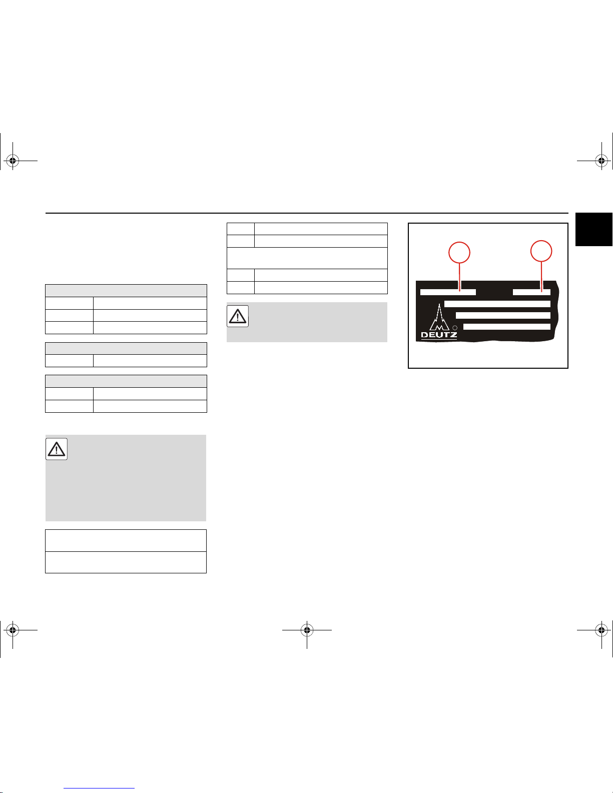
Rating plate
The type (A), engine number (B) and performance
data are stamped on the rating plate.
The engine type and number must be stated when
purchasing spare parts.
DEUTZ AGDEUTZ AG
MADE IN GERMANYMADE IN GERMANY
Mot.-Typ
Mot.-Nr.Mot.-Nr.
R
B
A
OBJ_DOKU-44425-001.fm Seite 7 Montag, 7. Juli 2014 7:46 07
Engine description Model
8 © 2014
2
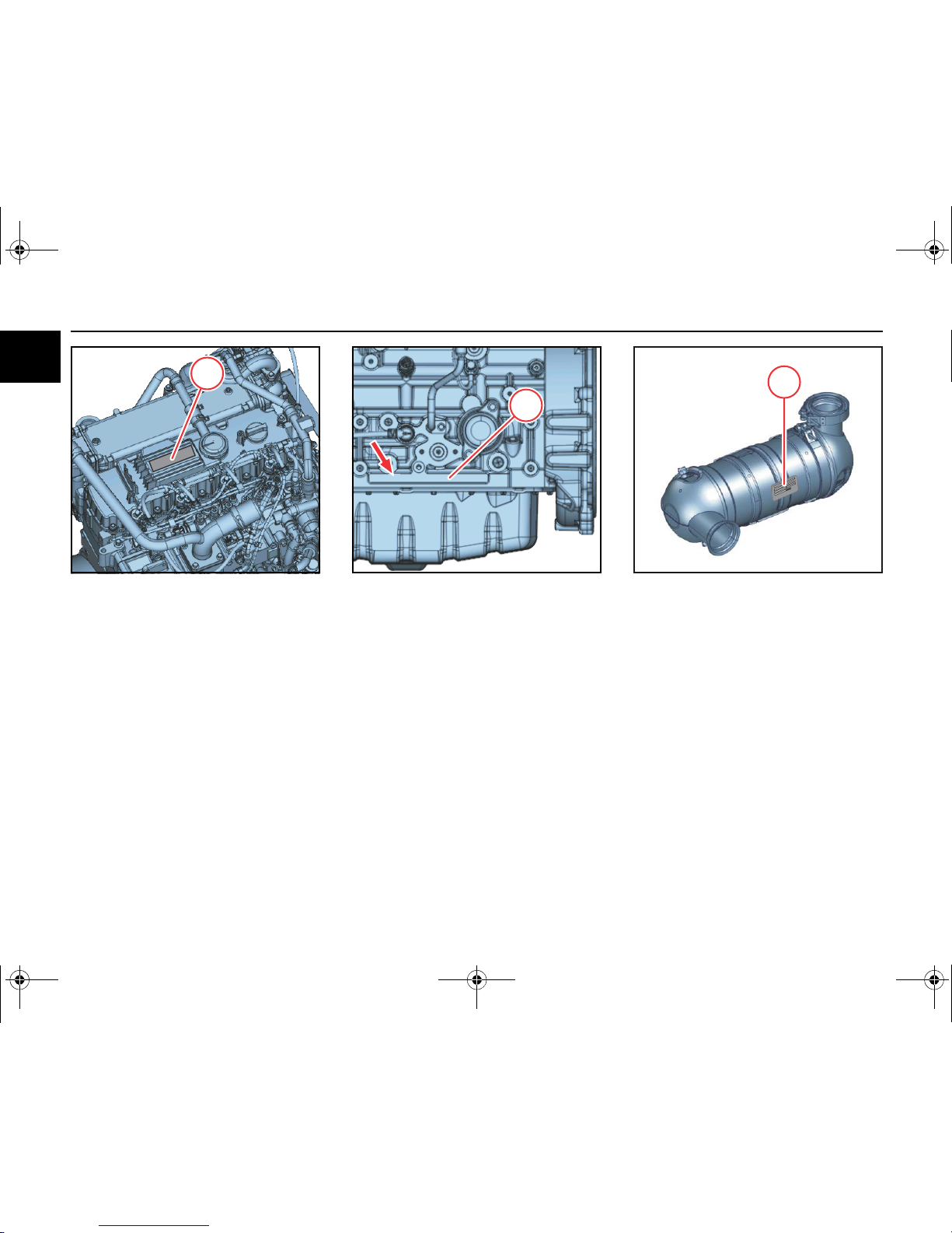
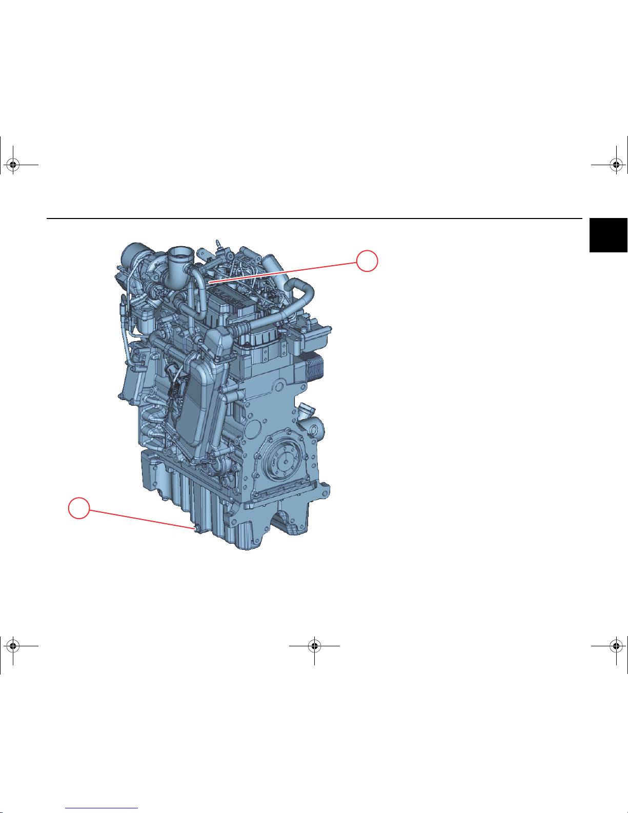
Location of the rating plate
The rating plate (C) is fixed to the cylinder head cov
-
er or the crankcase.
C
Engine serial number
The engine number (D) is stamped onto the crank
-
case (arrow) and onto the rating plate.
XX
XXXXX
D
Serial numbers of the exhaust aftertreatment com
-
ponents
The serial numbers of the exhaust aftertreatment
components are stamped on the rating plates.
1 Rating plate of the diesel oxidation catalytic
converter
1
OBJ_DOKU-44425-001.fm Seite 8 Montag, 7. Juli 2014 7:46 07
Model Engine description
© 2014 9
2
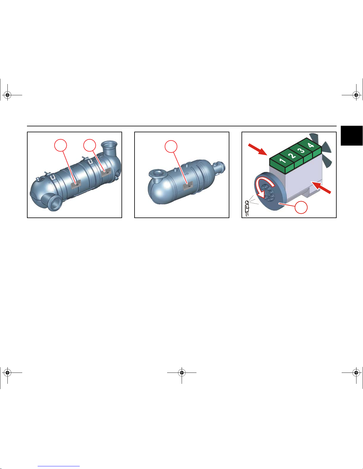
Serial numbers of the exhaust aftertreatment com
-
ponents
The serial numbers of the exhaust aftertreatment
components are stamped on the rating plates.
1 Rating plate of the diesel oxidation catalytic
converter
2 Rating plate of the diesel particle filter
2 1
Serial numbers of the exhaust aftertreatment com
-
ponents
The serial numbers of the exhaust aftertreatment
components are stamped on the rating plates.
1 Rating plate of the SCR catalyst
1
Cylinder numbering
Cylinder arrangement
The cylinders are counted consecutively starting
from flywheel (1).
Direction of rotation
Looking onto the flywheel.
rotating to the left: counter-clockwise.
Engine sides
Looking onto the flywheel.
1
left
right
OBJ_DOKU-44425-001.fm Seite 9 Montag, 7. Juli 2014 7:46 07
Engine description Engine illustrations
10 © 2014
2
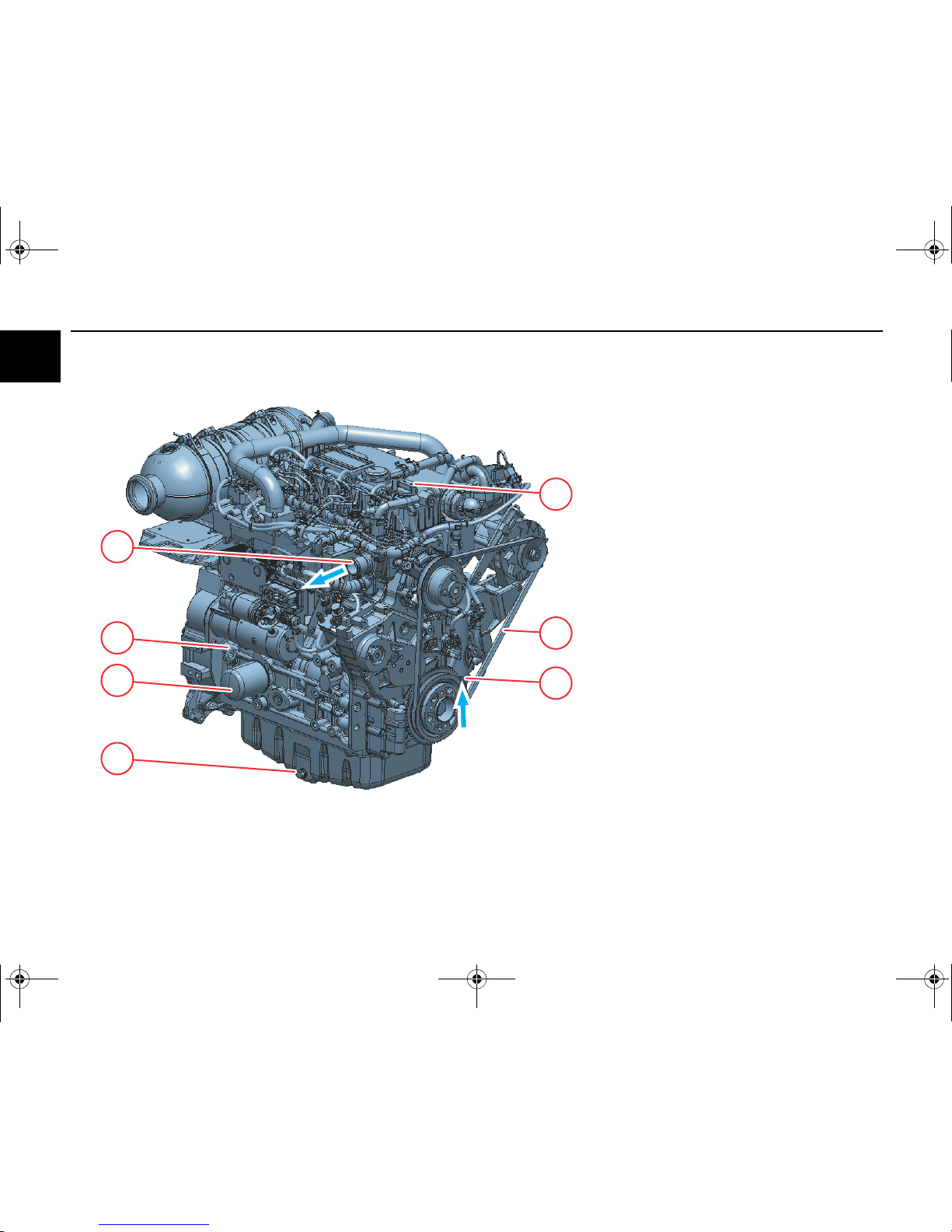
3
1
2
6
5
4
7
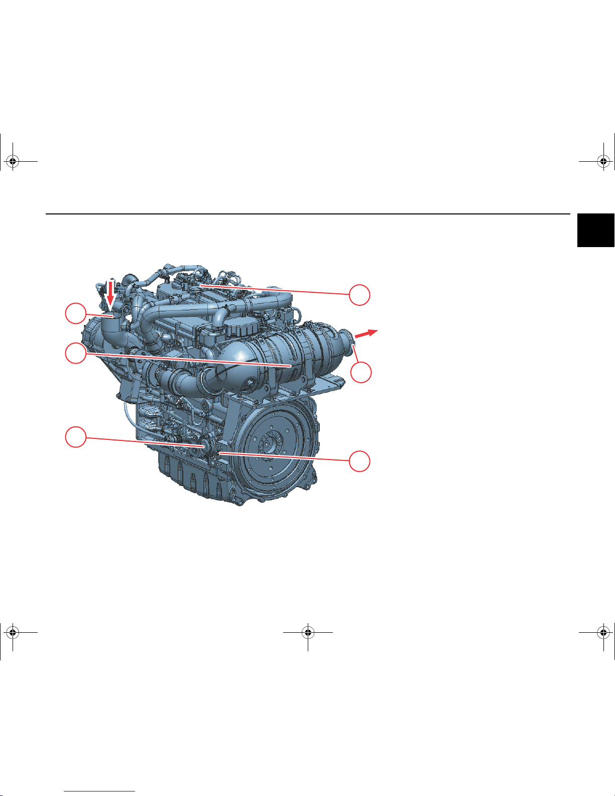
TD 3.6 L4
Industrial engine
View from right (example)
1 Lubricating oil filling
2 V-belts
3 Coolant inlet
4 Lubricating oil drain plug
5 Lube oil replacement filter
6 Lubricating oil dipstick
7 Coolant outlet
OBJ_DOKU-44425-001.fm Seite 10 Montag, 7. Juli 2014 7:46 07
Engine illustrations Engine description
© 2014 11
2
2
4
3
5
1
6
TD 3.6 L4
Industrial engine
View from left (example)
1 Combustion air inlet
2 Crankcase breather
3 Exhaust outlet
4 Lubricating oil dipstick
Optional
5 Lube oil replacement filter
Optional
6 Diesel oxidation catalytic converter
OBJ_DOKU-44425-001.fm Seite 11 Montag, 7. Juli 2014 7:46 07
Engine description Engine illustrations
12 © 2014
2
5
2
3
1
4
8
7
10
6
9
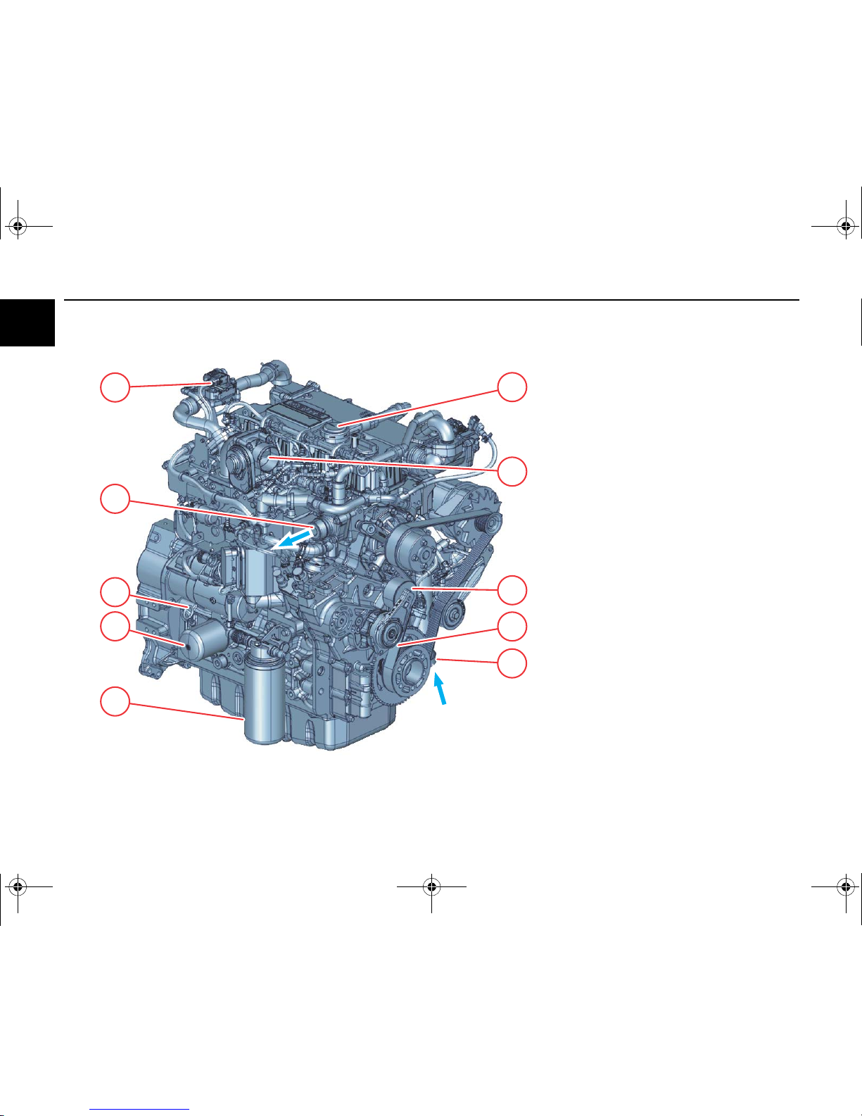
TCD 3.6 L4
Industrial engine
View from right (example)
1 Crankcase breather
2 Throttle valve
3 Tension pulley
4 V-rib belt
5 Coolant inlet
6 Lubricating oil drain plug
7 Lube oil replacement filter
8 Lubricating oil dipstick
9 Coolant outlet
10 Differential pressure flow meter
OBJ_DOKU-44425-001.fm Seite 12 Montag, 7. Juli 2014 7:46 07
Engine illustrations Engine description
© 2014 13
2
5
3
2
1
4
6
TCD 3.6 L4
Industrial engine
View from left (example)
1 Combustion air inlet
2 Lube oil cooler
3 Lubricating oil dipstick
Optional
4 Lube oil replacement filter
Optional
5 Generator
6 Lubricating oil filling
OBJ_DOKU-44425-001.fm Seite 13 Montag, 7. Juli 2014 7:46 07
Engine description Engine illustrations
14 © 2014
2
5
2
3
1
4
8
7
10
6
9
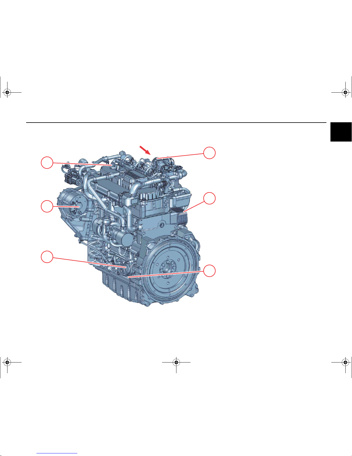
TCD 3.6 L4
Agricultural technology
View from right (example)
1 Exhaust outlet
2 Lubricating oil filling
3 V-rib belt
4 Tension pulley
5 Coolant inlet
6 Lubricating oil drain plug
7 Lubricating oil filling
8 Lube oil replacement filter
9 Coolant outlet
10 Combustion air inlet
OBJ_DOKU-44425-001.fm Seite 14 Montag, 7. Juli 2014 7:46 07
Engine illustrations Engine description
© 2014 15
2
1
2
TCD 3.6 L4
Agricultural technology
View from right (example)
1 Crankcase breather
2 Lubricating oil drain plug
OBJ_DOKU-44425-001.fm Seite 15 Montag, 7. Juli 2014 7:46 07
Engine description Lubricating oil diagram
16 © 2014
2
1
4
5
12
13
15 14
11
8
710 6932
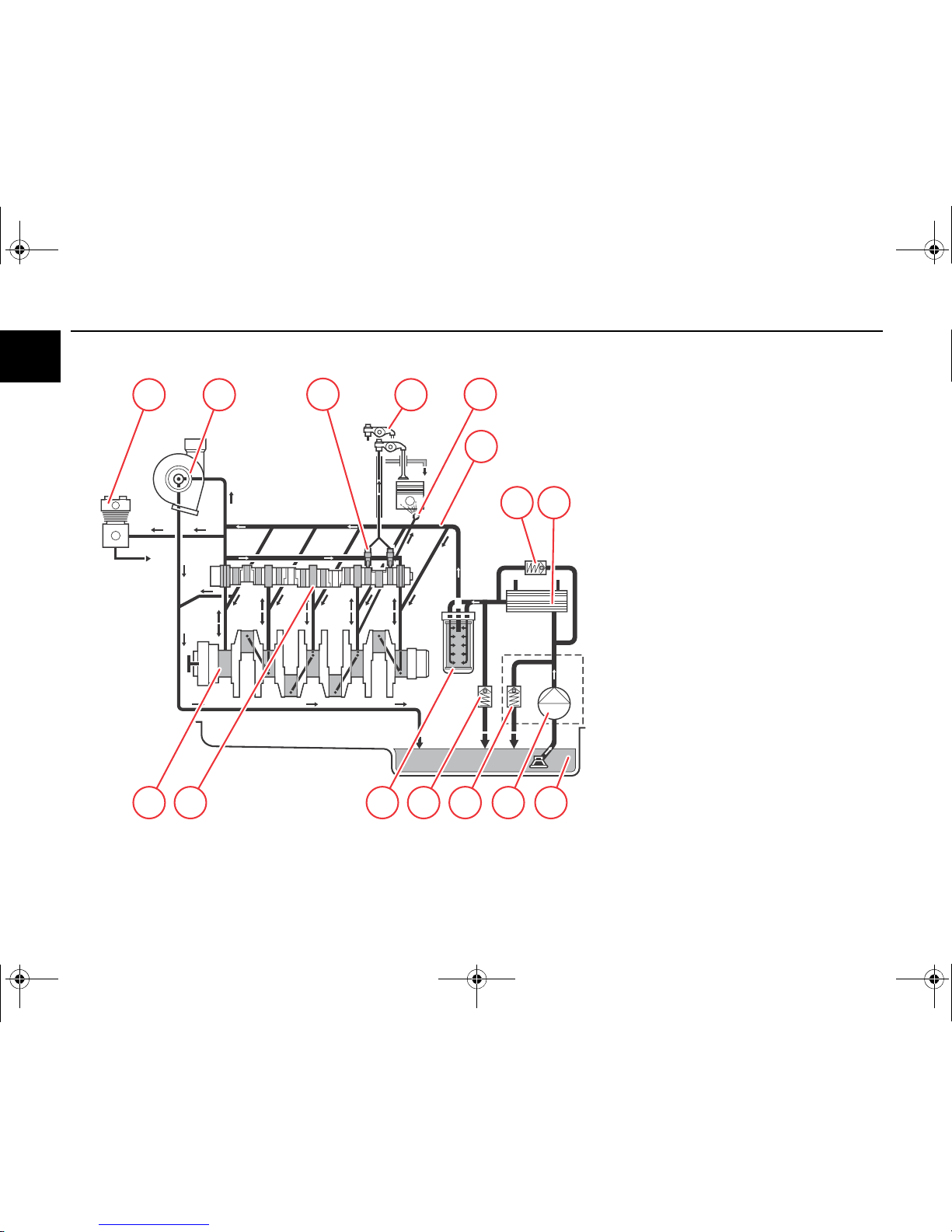
Lubricating oil system
(example)
1 Lubricating oil sump
2 Lubricating oil pump
3 Overpressure valve
4 Lube oil cooler
5 Bypass valve
6 Pressure control valve
7 Lubricating oil filter
8 Main lube oil channel
9 Camshaft bearing
10 Crankshaft bearing
11 Piston cooling nozzle
12 Rocker arm
13 Hydraulic tappets
14 Turbocharger
15 Air compressor
Optional
OBJ_DOKU-44425-001.fm Seite 16 Montag, 7. Juli 2014 7:46 07
Fuel diagram Engine description
© 2014 17
2
12
7
8910
61154312
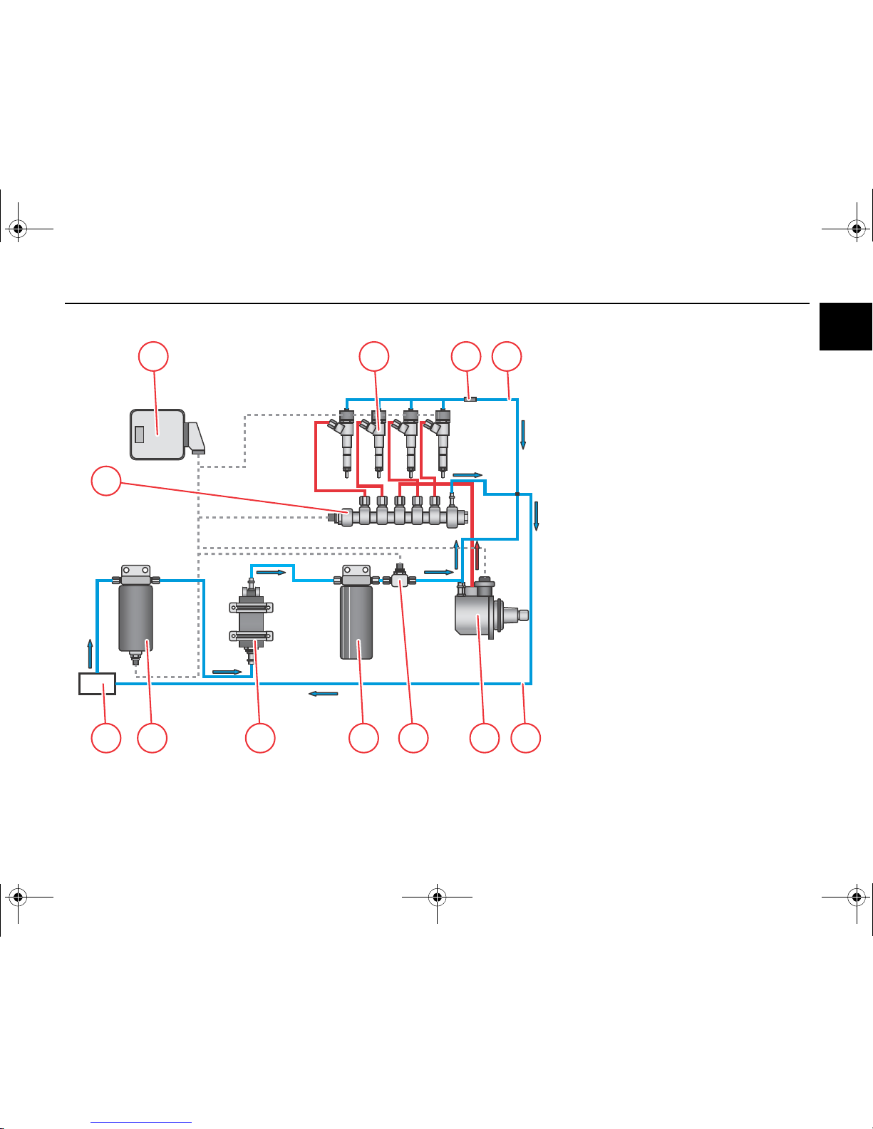
Fuel schematic (example)
1 Fuel tank
2 Fuel pre-filter
3 Fuel pump
(electrically powered)
4 Exchangeable fuel filter
5 Fuel transducer
6 High-pressure pump
with
– Control block FCU (Fuel Control Unit)
7Rail
8 Injector
9 Check valve
10 Return line
11 Fuel return to fuel tank
12 Engine control unit
OBJ_DOKU-44425-001.fm Seite 17 Montag, 7. Juli 2014 7:46 07
Engine description Coolant diagram
18 © 2014
2
x1
x2
1
2
3
4
T
x1
610
987
123
4
x2
5
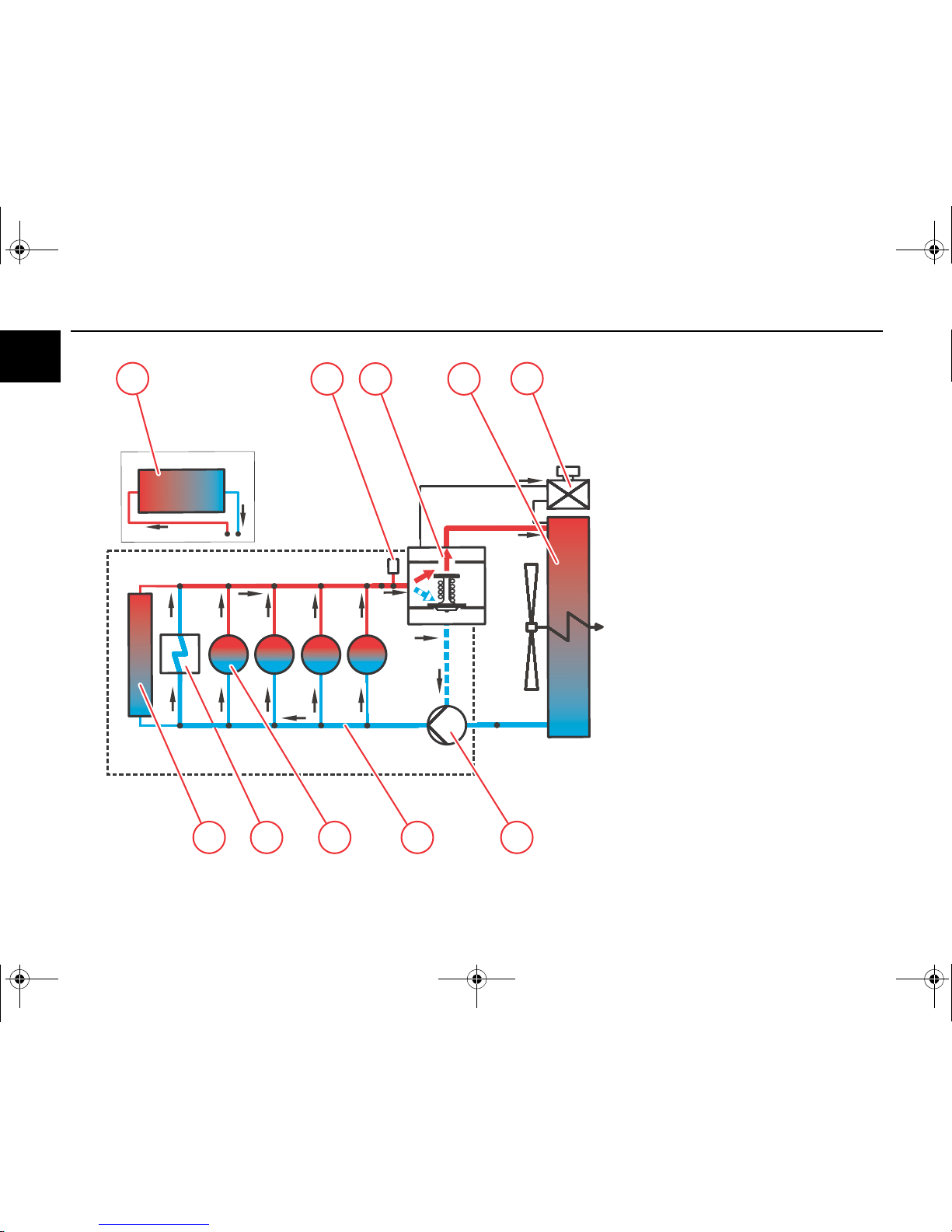
Coolant schematic (example)
1 Coolant pump
2 Coolant supply for engine cooling
3 Cylinder pipe/head cooling
4 Lube oil cooler
5 Exhaust return cooler
6 Connection possibility for cab heating
7 Temperature transmitter
8 Thermostat
9 Cooler
10 Compensation tank
OBJ_DOKU-44425-001.fm Seite 18 Montag, 7. Juli 2014 7:46 07
Exhaust gas recirculation Engine description
© 2014 19
2
89
7
1
54
32
6
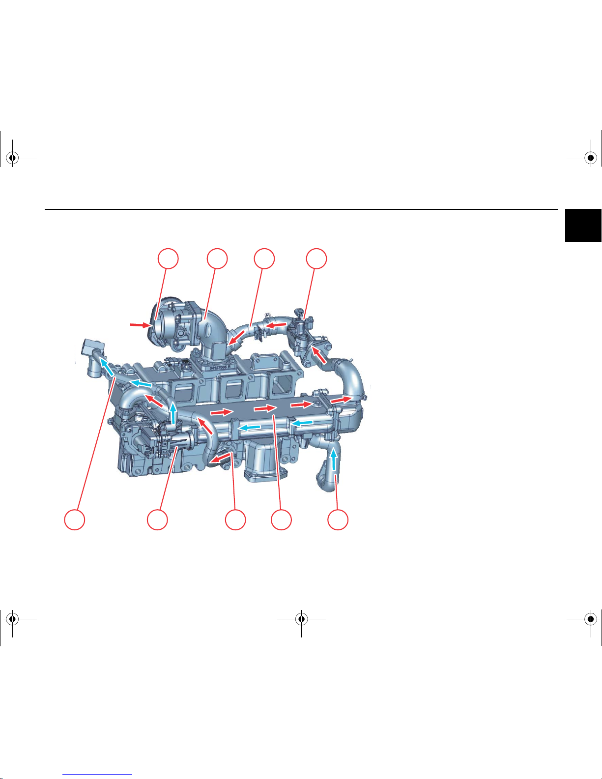
External exhaust gas recirculation
1 Exhaust gas partial flow
(uncooled)
2 Actuator
(electrically actuated)
3 Coolant return
4 Exhaust return cooler
5 Coolant line to the EGR cooler
6 Differential pressure flow meter
7 Exhaust gas partial flow
(cooled)
8 Mixing pipe
9 Throttle valve
OBJ_DOKU-44425-001.fm Seite 19 Montag, 7. Juli 2014 7:46 07
Engine description Exhaust gas aftertreatment
20 © 2014
2
2
3
4
5
6
7
1
9
8
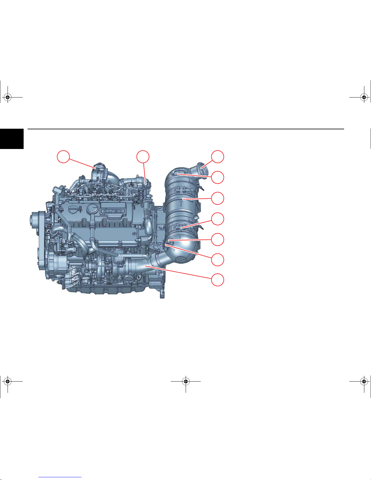
Exhaust aftertreatment system
Example:
1 Decoupling line
2 Differential pressure sensor
3 Exhaust temperature sensor
4 Diesel oxidation catalytic converter
5 Diesel particle filter
Optional
6 Differential pressure sensor
7 Exhaust outlet
8 Differential pressure flow meter
9 Throttle valve
OBJ_DOKU-44425-001.fm Seite 20 Montag, 7. Juli 2014 7:46 07
Exhaust gas aftertreatment Engine description
© 2014 21
2
2
10
1
7
8
435
13
9
12
6
11
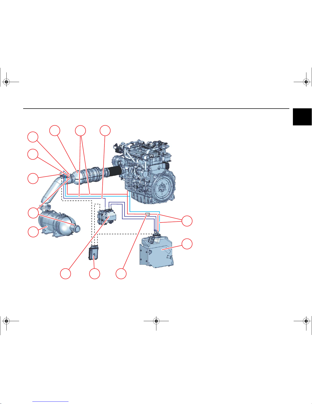
Exhaust aftertreatment system
Example:
1 Coolant line
to pre-heat the AdBlue® tank
2AdBlue
®
tank
3 Solenoid valve
4 Engine control unit
5 AdBlue® supply pump
6 SCR catalytic converter
7NO
X
sensor
8 Dosing device
9 Pressure sensor
10 Temperature transmitter
11 Diesel oxidation catalytic converter
12 Coolant line
to cool the dosing device
13 AdBlue® line
OBJ_DOKU-44425-001.fm Seite 21 Montag, 7. Juli 2014 7:46 07
Engine description Electrics/Electronics
22 © 2014
2
2
11
9
12
13
10
32 4 5
7
8
1
6
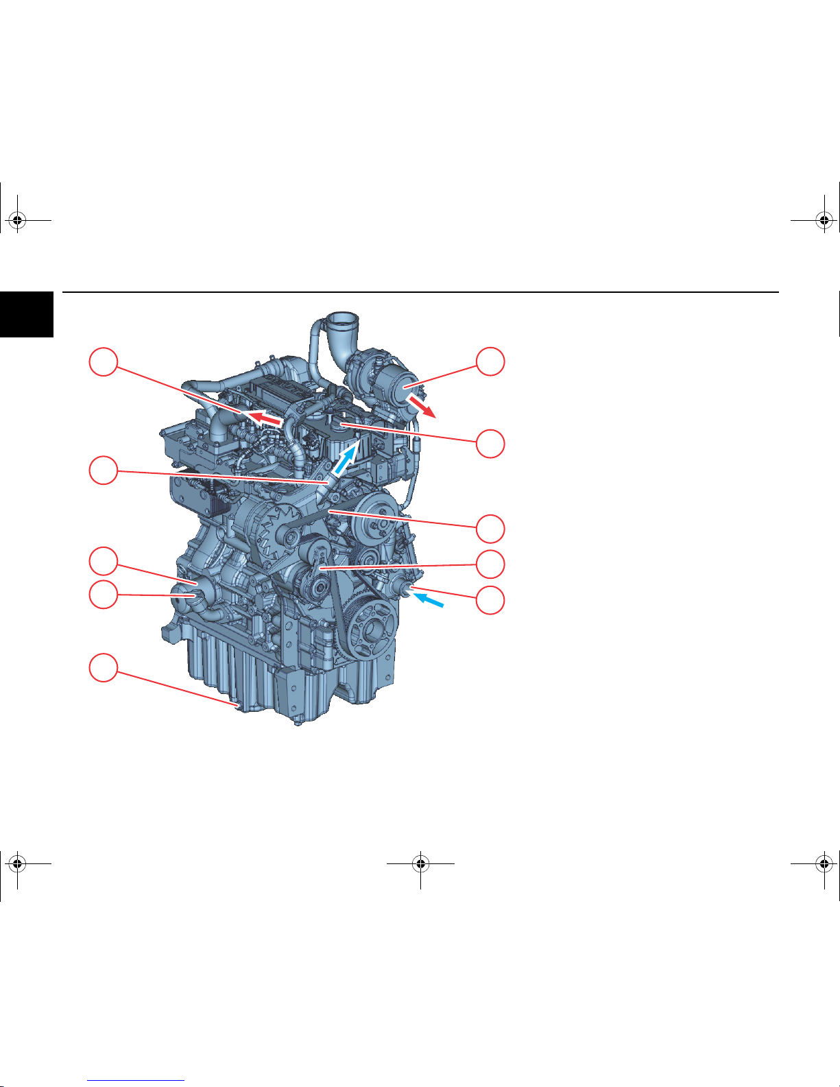
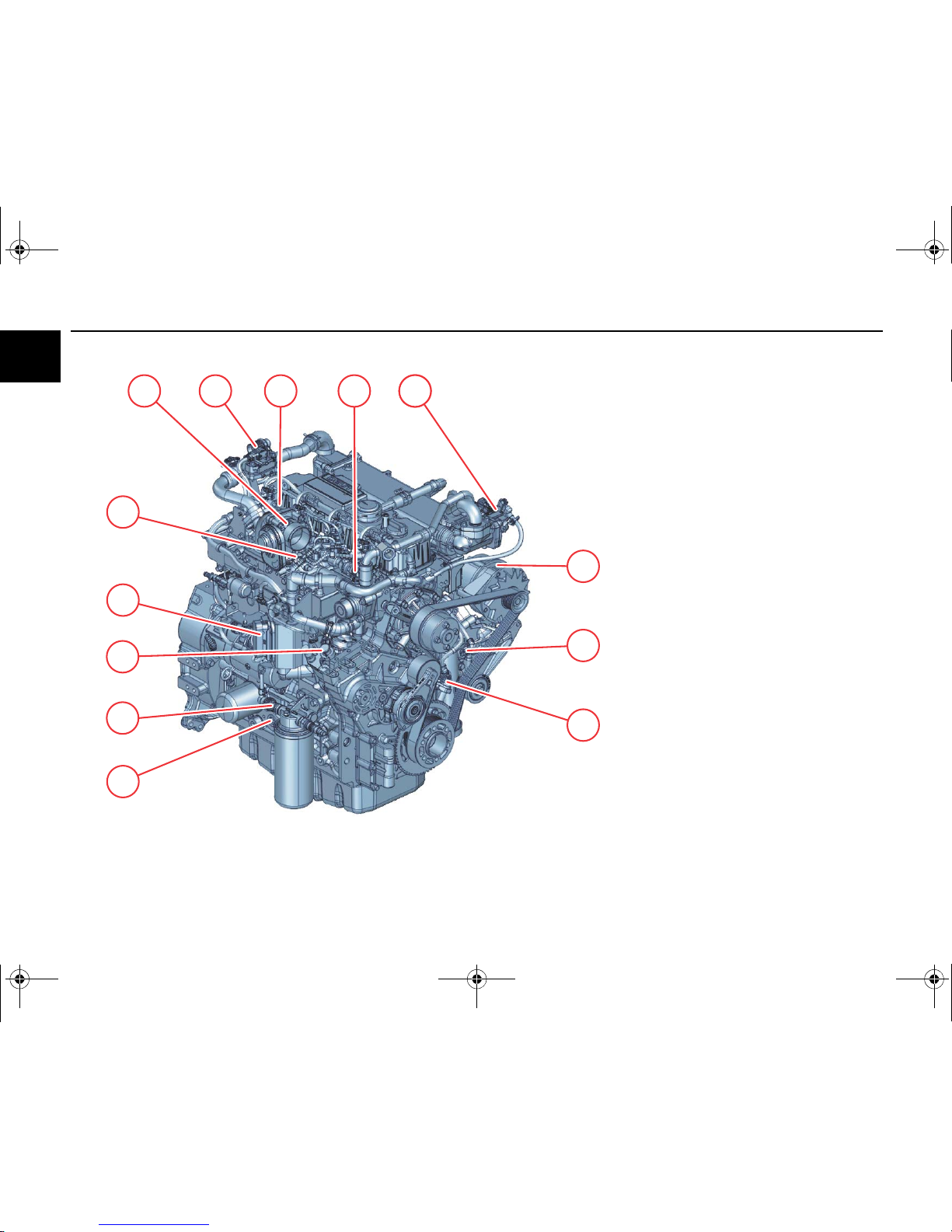
Electronic engine control
1 Throttle valve
2 Differential pressure flow meter
3 Rail pressure sensor
4 Coolant temperature transmitter
5 Actuator
6 Generator
7 Speed transmitter via camshaft
8 Speed transmitter via crankshaft
9 Fuel transducer
10 Lubricating oil pressure transmitter
(on the opposite side)
11 High-pressure pump
12 Central plug (for engine control)
13 Charge air pressure transmitter, charge air tem
-
perature transmitter
OBJ_DOKU-44425-001.fm Seite 22 Montag, 7. Juli 2014 7:46 07
Electrics/Electronics Engine description
© 2014 23
2
Information about the engine electronics
This engine is equipped with an electric control unit.
The equipping of the respective system depends on
the desired scope of function and the planned type of
engine application.
The resultant wiring with pin assignment can be seen
in the appropriate wiring diagram.
The installation regulations of the DEUTZ AG must
also be taken into account.
Precautions
The connections of the control units are
only dust and water proof when the mating
plugs are plugged (protection class IP69K)!
The control units must be protected against
spray water and moisture until plugging in
the mating plugs!
Reverse polarity can lead to failure of the
control unit.
To avoid damaging the control units, all the
connections on the control unit must be dis
-
connected before electric welding work.
Interventions in the electrical system con
-
trary to the DEUTZ regulations or by un
-
qualified personnel can permamently
damage the engine electronics and have
serious consequences which are not cov
-
ered by the manufacturer's guarantee.
Installation instructions
The control units are calibrated to the respective en
-
gine and identified by the engine number. Every en
-
gine may only be operated with the appropriate
control unit.
Setpoint transmitters (pedal value transmitters) nec
-
essary for vehicle operation must be connected to
the vehicle side cable harness and calibrated with
the DEUTZ diagnostic program SERDIA (SERvice
DIAgnosis). Wiring and cable assignment of the ve
-
hicle side cable harness must be taken from the con
-
nection diagram of the DEUTZ installation
consulting.
Supply voltage
12 Volt
24 Volt
It should be ensured that the battery is sufficiently
charged. If the supply voltage is interrupted while the
engine is running, this can lead to damage to the
electrics/electronics. If the supply voltage fails, the
engine shuts down.
Voltages above 32 Volt will destroy the control unit.
It is strictly prohibited:
a) to make changes or connections to the
wiring of the electrical control devices and
the data transmission cable (CAN lines).
b) to switch control units.
Otherwise guarantee rights will be lost!
Diagnostic and maintenance work may
only be carried out by authorised personnel
using equipment approved by DEUTZ.
Diagnostics
DEUTZ control units are equipped with self-diagnos
-
tics. Active and passive error entries are saved in the
error memory. Active errors are displayed on error
lamps/diagnostics lamps (
72).
A diagnosis can be made with:
● Error lamp (flash code)
● CAN bus
● DEUTZ electronics display
● Diagnostic socket (SERIDA)
Equipment-side wiring
The DEUTZ AG installation regulations should be
adhered to. In particular, the plug contact must be
crimped with the appropriate standard tools. If it is
necessary to do so, plugged-in contacts may only be
removed from the plug housing with the proper tools.
OBJ_DOKU-44425-001.fm Seite 23 Montag, 7. Juli 2014 7:46 07
Operation Ambient conditions
24 © 2014
3
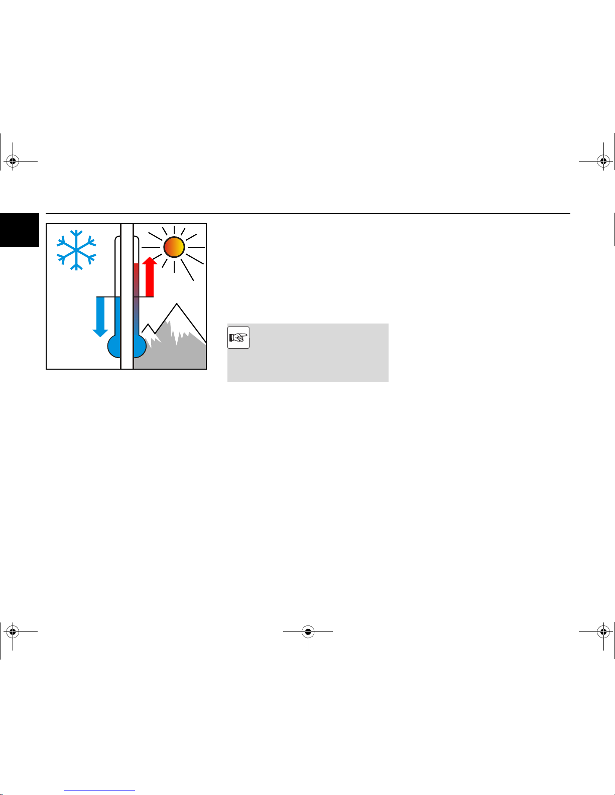
Low ambient temperatures
Lubricating oil
● Select the lubricating oil viscosity according to
the ambient temperature.
● If cold starting occurs frequently cut the lube oil
changing interval by half.
Fuel
● Use winter fuel below 0 °C (
45).
Battery
● A good charging condition of the battery (
65)
is the prerequisite for starting the engine.
● Heating up the battery to approx. 20°C improves
the starting behaviour of the engine. (Remove
and store the battery in a warm room).
0 °C
Cold start aid
● Depending on the type of engine, glow plugs,
heating plugs, heating flange, flame glow system
can be used as cold starting aids.(
28)
Coolant
● Observe the mixing ratio anti-freeze/cooling wa
-
ter. (46)
High ambient temperatures, high altitude
Under the following application and operating condi
-
tions, the amount of fuel must be reduced.
● Application at high altitude
● Application at high ambient temperatures
Reason: Air density decreases as altitude or ambient
temperature increase. This reduces the amount of
oxygen in the engine intake air and the fuel-air mix
-
ture would be too rich if the injected amount of fuel
were not reduced.
● The results would be:
– high engine temperature
– reduction in engine performance
– possible impairment of starting behaviour
Consult your equipment supplier or DEUTZ partner if
you have any other questions.
This engine is equipped with an electric
control unit.
Under the operating conditions listed be
-
low, the amount of fuel is reduced automat
-
ically, controlled by the electronic control
unit.
OBJ_DOKU-44425-001.fm Seite 24 Montag, 7. Juli 2014 7:46 07
Initial commissioning Operation
© 2014 25
3
Preparations for initial commissioning
(Maintenance schedule E 10)
● Remove engine corrosion protection
● Remove any transport devices.
● Check the battery and cable connections and
mount if necessary.
● Check belt tension (
63).
● Have the engine monitor or warning system
checked by authorised personnel.
● Check the engine mounting.
● Check that all hose unions and clips fit properly.
The following additional work must be carried out on
generally overhauled engines:
● Check the fuel pre-filter and main filter and
change if necessary.
● Check the intake air cleaner (if available, main
-
tain according to maintenance indicator).
● Drain lubricating oil and condensation water from
the charge air cooler.
● Fill with engine lube oil.
● Fill the coolant system (
79).
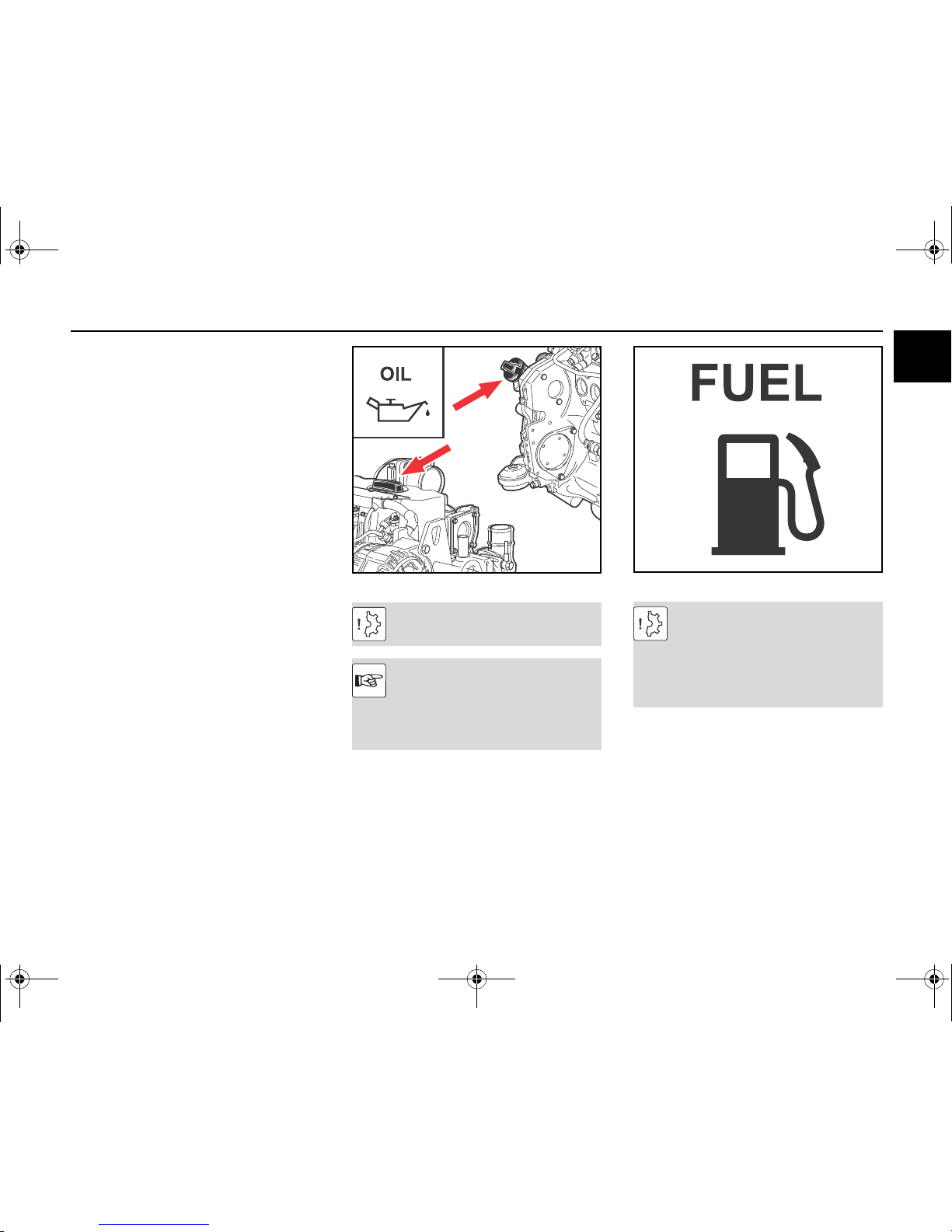
Fill with engine lube oil
● Fill the engine with lubricating oil via the lubricat
-
ing oil filler neck.
● Observe the lubricating oil filling level (
79).
Low lubricating oil level and overfilling lead
to engine damage.
The engines are generally supplied without
lubricating oil filling.
Select lubricating oil quality and viscosity
before filling.
Order DEUTZ lubricating oils from your
DEUTZ partner
Pour in fuel
● The fuel low pressure system must be vented be
-
fore the first start-up after filling with the manualy
supply pump.
Only use clean commercially available brand diesel
fuel. Observe fuel quality (
45).
Use summer or winter-grade fuel, depending on the
ambient temperature.
Never fill the fuel tank while the engine is
running.
Ensure cleanliness.
Do not spill fuel.
Additional venting of the fuel system by a 5
minute trial run at idle speed or on low load
is absolutely essential.
OBJ_DOKU-44425-001.fm Seite 25 Montag, 7. Juli 2014 7:46 07
Operation Initial commissioning
26 © 2014
3
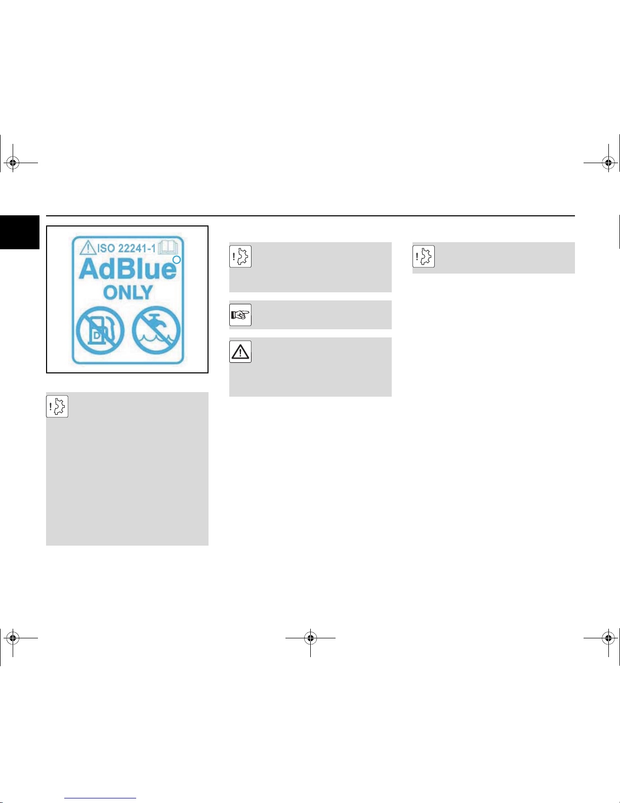
Filling with AdBlue®
Only re-fuel when the engine is not running.
Only fill with AdBlue®!
Other media (e.g. diesel), even in the
smallest amounts, can cause destruction of
the system and a not emmission compliant
operation.
If you have filled with e.g. diesel and this
has got into the system, the complete
AdBlue® injection system must be re
-
placed!
If the filled medium (e.g. diesel) has not
reached the lines and supply pump/meter
-
ing module, an emptying and thorough
cleaning of the AdBlue® tank will be ade
-
quate.
Ensure cleanliness.
R
Filling the coolant system
The coolant must have a prescribed con
-
centration of cooling system corrosion pro
-
tection agent!
Never operate the engine without coolant,
even for a short time!
Order coolant corrosion protection agent
from your DEUTZ partner.
Danger of scalding from hot coolant!
Cooling system under pressure! Only open
the cap when cool!
Observe safety regulations and national
specifications when handling cooling me
-
dia.
Trial run
Carry out a brief trial run up to operating temperature
(approx. 90 °C) after preparations.
Do not load the engine if possible.
● Work with the engine not running:
– Check engine for tightness.
– Check lubricating oil level, if necessary top
up.
– Check the coolant level and top up coolant if
necessary.
● Work during the trial run:
– Check engine for tightness.
Additional venting of the fuel system by a 5
minute trial run at idle speed or on low load
is absolutely essential.
OBJ_DOKU-44425-001.fm Seite 26 Montag, 7. Juli 2014 7:46 07
 Loading...