


 Loading...
Desa VgM36h, VgM36, VgM42h, VgM50, VgM42 User Manual
...Residential Woodburning Fireplace
OWNER’S OPERATION AND INSTALLATION MANUAL
(V)GM36, (V)GM42 and (V)GM50
Wood Burning Masonry Fireplaces with Insulation (V)GM36H, (V)GM42H and (V)GM50H
Wood Burning Herringbone Masonry Fireplaces with Insulation
SAVE THIS BOOK
This book is valuable. In addition to instructing you on how to install and maintain your appliance, it also contains information that will enable you to obtain replacement parts or accessory items when needed. Keep it with your other important papers.
This fireplace is approved for use as a wood burning fireplace or for use with a vented gas log approved to
ANS Z21.60, Z21.84 or RGA 2-72 standards or for use with a vent-free gas log heater approved to ANS Z21.11.2 standard.
This wood burning fireplace complies with UL127- CAN/ULS-S610-M87 standard as a FACTORY BUILT APPLIANCE.
FOR CANADA: The authority having jurisdiction (such as the municipal building department, fire department, etc.) should be contacted before installation to determine the need to obtain a permit.
Save this manual for future reference.
For more information, visit www.desatech.com
WARNING: Improper installation, adjustment, alteration, service or maintenance can cause injury, property damage or loss of life. Refer to this manual for assistance or additional information. Consult a qualified installer or local distributor.
Table of Contents
Safety Information................................................ |
2 |
Brick Installation................................................. |
14 |
Specifications....................................................... |
3 |
Glass Door Installation....................................... |
22 |
Fireplace Installation............................................ |
6 |
Operation and Maintenance Guidelines............. |
23 |
Venting Installation............................................... |
8 |
Technical Service............................................... |
24 |
Optional Gas Line Installation............................ |
12 |
Replacement and Accessory Parts.................... |
25 |
Safety Information
IMPORTANT: Check local codes before installing this fireplace.
Before beginning the installation of the fireplace, read these instructions through completely.
•This DESA fireplace and its components are safewheninstalledaccordingtothisinstallation manual. Unless you use DESA components, which have been designed and tested for the fireplace system, you may cause a fire hazard.
•The DESA warranty will be voided by and DESA disclaims any responsibility for the following actions.
a.Modification of the fireplace, components, doors, air inlet system and damper control.
b.Use of any component part not manufac- turedorapprovedbyDESAincombination with a DESA fireplace system.
Proper installation is the most important step in ensuring safe and continuous operation of the fireplace. Consult the local building codes as to the particular requirements concerned with the installation of all factory built fireplaces.
 WARNING: Do not install a fireplaceinsertinthisboxunless the manufacturer's instructions with the insert specifically state thisfireplacehasbeentestedfor use with this insert.
Thisfireplaceisnotintendedtobe used as a substitute for a furnace to heat an entire home. Use for supplemental heat only.
FOR YOUR SAFETY
•Do not store or use gasoline oranyotherflammablevapors or liquids in the vicinity of this or any other appliance.
•Due to high temperatures, the appliance should be located out of traffic and away from furniture and draperies.
•Do not place clothing or other flammablematerialsonornear the appliance.
•Never leave children unattended when a fire is burning in the fireplace.
 WARNING: Use solid wood or processed solid fuel firelogs only. When processed wood fuel fire logs are used, do not poke or stir the logs while they are burning. Use only fire logs that have been evaluated for the application in fireplace and refer to fire log warnings and caution markings on packaging prior to use.
 WARNING: Always leave glass doors fully opened or fully closed when operating fireplace.
www.desatech.com |
112435-01M |
Specifications
Models VGM36(H) and GM36(H)
ROUND TOP TERMINATION SQUARE CHASE-TOP
TERMINATION
1" CHIMNEY AIRSPACE CLEARANCE TO COMBUSTIBLE MATERIAL
|
|
NO COMBUSTIBLE |
|
|
MATERIAL ON FACE |
|
|
COMBUSTIBLE |
|
|
WALL BOARD |
11/2" AIR SPACE |
|
|
BACK AND SIDES |
|
|
OUTSIDE AIR |
|
|
|
|
MINIMUM 12" TO |
|
|
PERPENDICULAR |
|
|
SIDEWALL |
GAS LINE |
|
HEARTH EXTENSION |
KNOCKOUTS |
|
|
|
60" X 20" |
|
|
|
|
0" TO |
12" EACH SIDE |
|
BOTTOM |
|
|
|
12" |
29" |
|
|
7.5" |
67" |
|
22" |
58" |
26.625" |
|
|
|
|
|
|
49" |
30" |
|
|
|
0.625" |
45" |
|
|
|
|
|
8" |
36" |
|
|
45" |
|
|
|
|
|
|
|
|
1" |
|
AIR KIT |
|
|
|
|
|
21.5" |
LEFT SIDE |
KNOCK OUT |
|
|
GAS LINE |
|
|
|
|
|
|
|
|
KNOCK OUTS |
|
|
|
3.5" |
|
10.5" |
|
9.5" |
|
20" |
|
|
|
|
7" |
|
|
|
10.75" |
|
|
|
15.375" |
|
|
36" |
|
|
112435-01M |
www.desatech.com |

Specifications Continued
Models VGM42(H) and GM42(H)
ROUND TOP TERMINATION SQUARE CHASE-TOP
TERMINATION
2" CHIMNEY AIRSPACE CLEARANCE TO COMBUSTIBLE MATERIAL
NO COMBUSTIBLE
MATERIAL ON FACE
11/2" AIR SPACE BACK AND SIDES
OUTSIDE AIR
GAS LINE
KNOCKOUTS
0" TO
BOTTOM
67"
58"
49"

 42" 8"
  51"
51"
1"
24.25"
41.25"
COMBUSTIBLE
WALL BOARD
MINIMUM 18" TO
PERPENDICULAR
SIDEWALL
HEARTH EXTENSION 66" X 20"
12" EACH SIDE
12"
30.5"
11"
21.25"
28.5"
30"
|
0.625" |
51" |
|
|
|
|
|
|
|
|
AIR KIT |
|
|
LEFT SIDE |
KNOCK OUT |
|
|
|
GAS LINE |
|
|
|
KNOCK OUTS |
|
|
|
3.5" |
23.5" |
10.5" |
|
9.5" |
|
|
|
|
|
|
8.5" |
|
|
|
13" |
|
|
|
17" |
|
www.desatech.com |
112435-01M |
Specifications Continued
Models VGM50(H) and GM50(H)
ROUND TOP TERMINATION |
SQUARE CHASE-TOP |
|
TERMINATION |
2" CHIMNEY AIRSPACE CLEARANCE TO COMBUSTIBLE MATERIAL
NO COMBUSTIBLE
MATERIAL ON FACE
COMBUSTIBLE
WALL BOARD
11/2" AIR SPACE BACK AND SIDES
OUTSIDE AIR
|
MINIMUM 18" TO |
|
PERPENDICULAR |
|
SIDEWALL |
GAS LINE |
|
KNOCKOUTS |
HEARTH EXTENSION |
|
|
0" TO |
74" X 20" |
12" EACH SIDE |
BOTTOM
|
12" |
|
|
|
|
38.5" |
|
67" |
|
|
11" |
|
|
|
|
58" |
|
|
21.25" |
28.5" |
|
|
|
49" |
|
|
|
30" |
|
|
|
|
0.625" |
59" |
|
|
50" |
|
|
8" |
|
|
|
59" |
|
|
|
|
|
|
|
|
1" |
|
|
|
|
|
AIR KIT |
|
|
LEFT SIDE |
KNOCK OUT |
|
32.75" |
|
|
|
|
GAS LINE |
|
|
|
|
|
|
|
|
KNOCK OUTS |
|
|
|
3.5" |
|
10.5" |
|
9.5" |
|
23.5" |
|
|
|
|
8.5" |
|
|
|
13" |
|
|
50" |
17" |
|
|
|
|
112435-01M |
www.desatech.com |
Fireplace Installation
selecting location
To determine the safest and most efficient location for the fireplace, you must take into consideration the following guidelines:
1.The location must allow for proper clearances (see Figures 1 and 2).
2.Consider a location where the fireplace will not be affected by drafts, air conditioning ducts, windows or doors.
3.A location that avoids the cutting of joists or roof rafters will make installation easier.
4.Anoutsideairkitisavailablewiththisfireplace
(see Optional Outside Air Kit on page 8).
Minimum clearance to combustibles
Back and sides of fireplace |
1 1/2" min.* |
Front of fireplace |
48" min. |
Floor** |
0" min. |
Perpendicular wall to opening |
18" min. |
Model GM36 |
12" min. |
Top spacers |
0" min. |
Mantel clearance |
see Mantels, page 7 |
Chimney outer pipe surface |
2" min. |
Models GM36 |
1" min. |
* Not required at nailing flanges ** See step 2 of Framing
 WARNING: Do not pack required air spaces with insulation or other materials.
Minimum/Maximum Chimney Height
The minimum height of the chimney, measured from the base of the fireplace to the flue gas outlet of the termination, is 16 feet for straight flue or a flue with one elbow set. The maximum distance between elbows is 6 feet. For systems with two elbow sets, the minimum height is 22 feet. The maximum height of any system is 50 feet. This measurement includes the fireplace, chimney sec- tions and the height of the termination assembly at the level of the flue gas outlet (see Figure 15, page 11).
Framing
1.Frame the opening for the fireplace using the dimensions shown in Figures 1 and 2.
2.If the fireplace is to be installed directly on carpeting, tile (other than ceramic) or any combustible material other than wood floor- ing, the fireplace must be installed upon a metal or wood panel extending the full width and depth of the fireplace.
3.Set the fireplace directly in front of this open- ing and slide the unit back until the nailing flanges touch the side framing.
4.Check the level of the fireplace and shim with sheet metal if necessary.
5.Beforesecuringfireplacetopreparedframing, theemberprotector(provided)mustbeplaced between the hearth extension (not supplied) and under the bottom front edge of the fire- placetoprotectagainstglowingembersfalling through. If the fireplace is to be installed on a raised platform, a Z-type ember protector (not supplied) must be fabricated to fit your requiredplatformheight.Theemberprotector should extend under the fireplace a minimum of 1 1/2". The ember protector should be made ofgalvanizedsheetmetal(28gaugeminimum to prevent corrosion.
6.Using screws or nails, secure the fireplace to the framing through flanges located on the sides of the fireplace.
 45.25" (36" Models)
51.25" (42" Models)
59" (50" Models)
67.125" |
58.125" |
30.125" |
28.250" (36" Models) |
Figure 1 - Framing Dimensions
61" (36" Models) |
Maintain 1 1/2" |
65" (42" Models) |
Clearance at Sides |
71" (50" Models) |
and Back of Fireplace |
|
1 1/2" Clearance |
|
Not Required at |
|
Nailing Flanges |
86.5" (36" Models)
92" (42" Models)
100" (50" Models)
Figure 2 - Corner Installation
www.desatech.com |
112435-01M |
Fireplace Installation
Continued
Hearth Extension
A hearth extension projecting a minimum of 20" in front of and a minimum of 12" beyond each side of the fireplace opening is required to protect combustible floor construction in front of the fire- place.Fabricateahearthextensionusingamaterial which meets the following specifications: a layer of noncombustible, inorganic material having a thermal conductivity of K=0.84 BTU IN/FT, HR. F (or less) at 1" thick. For example, if the material selected has a K factor of 0.25, such as glass fiber, the following formula would apply:
0.25 x 1.0" = 0.30" thickness required
0.84
Thermal conductivity "K" of materials can be obtained from the manufacturer or supplier of the noncombustible material. If the hearth extension istobecovered,usenoncombustiblematerialsuch as tile, slate, brick, concrete, metal, glass, marble, stone, etc. Provide a means to prevent the hearth extension from shifting and seal gap between the fireplace frame and hearth extension with a non- combustible material (see Figure 3).
 WARNING:Hearthextension
is to be installed only as shown
in Figure 3.
Seal Gap
Fireplace Front
Ember Protector
Fireplace Front |
|
Raised Hearth |
|
Ember Protector |
Hearth |
|
|
|
Extension |
Fireplace Front |
Seal Gap |
Elevated |
|
Ember Protector
Figure 3 - Hearth Extension
Mantels
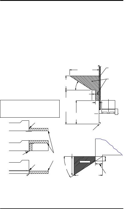
Amantelmaybeinstalledifdesired(seeFigure4). Woodworksuchaswoodtrims,mantelsoranyoth- er combustible material projecting from the front face must not be placed within 12" (GM36) or 18" (GM42/50) of the fireplace opening. Combustible materials above 12" (GM36) or 18" (GM42/50) and projecting more than 1 1/2" from the fireplace must not be placed less than 15" (GM36) or 21" (GM42/50) from the top opening of the fireplace (NFPA STD 211, Sec. 7-3.3.3).
Mantels or any other combustible material also may come up to the side edge of the black metal face of the fireplace just as long as the projection from the front face fall within the limit shown in Figure 4.
|
|
Combustible |
|
|
12 1/4" Ref. |
Material |
|
|
|
Safe |
|
6" |
|
Zone for |
|
Ref. |
33° |
Projection of |
|
|
Combustible |
||
|
|
||
|
3" Nom. |
Materials |
|
|
|
||
15" Min. |
|
|
|
(GM36) |
11/2" Max. |
|
|
21" Min. |
|
|
|
(GM42/50) |
|
|
|
12" Min. (GM36) |
Upper |
||
18" Min. (GM42/50) |
|||
Section of |
|||
|
|
||
|
|
Fireplace |
|
|
Fireplace |
|
|
|
Opening |
|
|
Top View of Fireplace
7.75" (GM36) |
FIREBOX |
|
11.5" (GM42/50) |
|
|
|
3" Max. |
|
SAFE ZONE |
4.5" |
|
33° |
||
|
||
Min. to |
Combustible |
|
Perpendicular |
||
Material Must |
||
Side Wall |
||
Not Overlap |
||
12" - GM36 |
||
Front Face |
||
18" - GM42/50 |
||
|
Figure 4 - Mantel Clearances to Combustible Material
112435-01M |
www.desatech.com |
|
Venting Installation
Optional Outside air Kit
(Model ak4/ak4f)
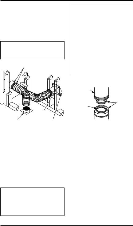
The installation of an outside air kit should be per- formed during the rough framing of the fireplace due to the nature of it's location. Outside combus- tion air is accessed through a vented crawl space (AK4F) or through a sidewall (AK4).
 CAUTION: Combustion air inlet ducts shall not terminate in attic space.
Secure to Collars with Metal Tape, Screws or Straps (Min. of 1/4" x 20" in size)
Air Inlet |
||
Location |
||
Must Allow |
||
For Bushes |
||
or Snow |
||
|
Air Inlet |
|
|
Eyebrow |
|
Vented Crawl Space |
Vent Hood |
|
Required for |
||
(Check Local Codes |
||
Wall Installation |
||
Before Installing in a |
||
|
||
Vented Crawl Space) |
|
|
Figure 5 - Outside Air Kit |
||
Chimney Pipe
The DESA chimney system consists of 12", 18", 24", 36"' and 48" snap-lock, double-wall pipe segments, planned for maximum adaptability to individual site requirements. Actual lengths gained after fitting overlaps must be taken into consideration (lineal gain) and are given in the lineal gain chart (see Figure 6). Lineal Gain is the actualmeasurablelengthofapartaftertwoormore partsareconnected.ForCanada,usechimneyparts designated "HT".
 WARNING: The opening in the collar around the chimney at the top of the fireplace must not be obstructed.Neveruseblowninsulation to fill the chimney enclosure.
LINEAL GAIN
PART NO. |
DESCRIPTION |
GAIN (IN) |
|
Georgian |
Fireplace |
66 1/2" |
|
12-12DM |
Pipe Section |
10 5/8" |
|
12-12HT |
|||
|
|
||
18-12DM |
Pipe Section |
16 5/8" |
|
18-12HT |
|||
|
|
||
24-12DM |
Pipe Section |
23 5/8" |
|
24-12HT |
|||
|
|
||
36-12DM |
Pipe Section |
34 5/8" |
|
36-12HT |
|||
|
|
||
48-12DM |
Pipe Section |
46 5/8" |
|
48-12HT |
|||
|
|
||
RLT-12D |
Round Termination |
7 3/4"* |
|
RLT-12HT |
|
|
|
STL-12D |
Square Chase-Top |
7" to 15"* |
|
|
with Slip Section |
|
* The lineal gain for the terminations is measured to the flue gas outlet height.
15" Galvanized
Outer Pipe
12 3/8" |
Hemmed |
Stainless |
End |
|
|
Inner Pipe |
|
Figure 6 - Lineal Gain
Assembly and installation of
double wall chimney system
Each double wall chimney section consists of a galvanized outer pipe, a stainless steel inner flue pipeandawirespacer.Thepipesectionsmustbeas- sembled independently as the chimney is installed. Whenconnectingchimneydirectlytothefireplace, the inner flue pipe section must be installed first with the lanced side up. The outer pipe section can then be installed over the flue pipe section with the hemmed end up. Press down on each pipe section untilthelancessecurelyengagethehemonthefire- placestarter.Thewirewillassuretheproperspacing between the inner and outer pipe sections.
Continuetoassemblechimneysectionsasoutlined above, making sure that both the inner and outer pipe sections are locked together. When install- ing double wall snap-lock chimney together, it is important to assure the joint between the chimney sections is locked. Check by pulling chimney upward after locking. The chimney will not come apart if properly locked. It is not necessary to add screws to keep the chimney together (exception, see Figure 9, page 10).
www.desatech.com |
112435-01M |
Venting Installation
Continued
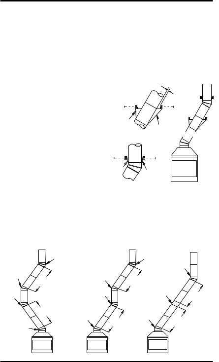
Using ELBOW offsets (30E-12DM)
1.To achieve desired offset, you may install combinations of 12", 18", 24", 36" and 48" length of double wall pipe (see offset chart and Figure 7).
OFFSET |
RISE |
|
CHIMNEY LENGTH |
|
||||
A |
B |
12" |
18" |
24" |
36" |
48" |
||
4 3/8" |
16 3/8" |
|
ELBOW SET ONLY |
|
||||
9 3/4" |
25 1/2" |
1 |
|
|
|
|
|
|
12 3/4" |
30 3/4" |
|
|
1 |
|
|
|
|
15" |
34 3/4" |
|
|
|
1 |
|
|
|
18" |
40" |
1 |
|
1 |
|
|
|
|
21 1/4" |
46 1/4" |
|
|
|
|
1 |
|
|
23 3/4" |
49 1/4" |
|
|
1 |
1 |
|
|
|
27 3/4" |
56 3/4" |
|
|
|
|
|
|
1 |
30" |
60 3/4" |
|
|
1 |
|
1 |
|
|
33" |
66" |
|
|
|
|
|
|
1 |
36" |
71" |
|
|
1 |
|
|
|
1 |
38 1/4" |
75" |
|
|
|
|
2 |
|
|
41 1/4" |
80 1/4" |
1 |
|
1 |
|
1 |
|
|
45" |
86 3/4" |
|
|
|
|
2 |
|
|
46 3/4" |
89 1/2" |
1 |
|
1 |
|
|
|
1 |
51" |
97" |
|
|
|
|
1 |
|
1 |
53 1/4" |
101" |
|
|
|
|
2 |
|
|
56 1/4" |
106 1/4" |
|
|
|
|
|
|
2 |
59 1/4" |
111 1/2" |
|
|
1 |
|
1 |
|
1 |
61 3/4" |
115 1/2" |
1 |
|
|
|
|
|
2 |
64 3/4" |
120 3/4" |
|
|
1 |
|
|
|
2 |
68 1/4" |
127" |
|
|
|
|
2 |
|
1 |
70" |
130" |
1 |
|
1 |
|
|
|
2 |
74 1/4" |
137 1/2" |
1 |
|
|
|
2 |
|
1 |
76 3/4" |
141 1/2" |
|
|
1 |
|
2 |
|
1 |
79 3/4" |
146 3/4" |
|
|
|
|
4 |
|
|
OFFSET CHART (22-50 FT. SYSTEM HEIGHT)
2.Chimney weight above offset rests on return elbow. Straps must be securely nailed to rafters or joists (see Figure 8, details a and b).
3.Maximum length of pipe between supports (return elbow or 12S-12DM) is 6' of angle run. Maximum of two 6' angle run sections per chimney system (see Figure 7).
4.All pipe connections between the offset and return must be secured with two screws on the outer pipe only (see Figure 9, page 10). Do not penetrate the inner stainless.
See Detail A

 2" Min.
Straps
Detail BStraps |
See Detail B |
|
Angle Firestop |
||
|
Straps
Straps
Detail A
Return Elbow
Figure 8 - Ceiling Support Pipe
12S-12DM
|
Return |
|
Return |
|
|
|
Elbow |
|
Elbow |
|
|
Offset |
|
Offset |
|
Return |
|
Elbow |
|
|
Elbow |
|
|
|
Elbow |
6' Max. |
|
||
|
6' Max. |
Ceiling |
|
||
|
|
|
|||
Return |
|
|
|
Support Pipe |
|
|
Return |
|
12S-12DM |
6' Max. |
|
Elbow |
|
|
|||
|
Elbow |
|
|
|
|
|
|
|
|
|
|
|
6' Max. |
Offset |
Offset |
|
|
|
|
|
|
||
Offset |
|
Elbow |
6' Max. Elbow |
6' Max. |
|
|
|
|
|
|
|
Elbow |
|
|
|
|
|
|
A |
|
B |
C |
|
|
Figure 7 - Typical Offset Terminations |
|
|
||
112435-01M |
www.desatech.com |
|
Loading...