

UNVENTED (VENT-FREE) BLUE FLAME GAS HEATER
SAFETY INFORMATION AND INSTALLATION MANUAL
18,000 BTU THERMOSTAT MODELS
LSL18NT, LSL18PT, SL18NT, SL18PT, VSL18NT AND VSL18PT
WARNING: If the information in this manual is not followed exactly, a fire or explosion may result causing
property damage, personal injury or loss of life.
— Do not store or use gasoline or other flammable
vapors and liquids in the vicinity of this or any other
appliance.
— WHAT TO DO IF YOU SMELL GAS
• Do not try to light any appliance.
• Do not touch any electrical switch; do not use any
phone in your building.
• Immediately call your gas supplier from a neighbor’s
phone. Follow the gas supplier’s instructions.
• If you cannot reach your gas supplier, call the fire
department.
— Installation and service must be performed by a quali-
fied installer, service agency or the gas supplier.
Save this manual for future reference.
For more information, visit www.desatech.com
WARNING: Improper installation, adjustment, alteration, service or maintenance can cause injury or property damage. Refer to this manual for correct installation
and operational procedures. For assistance or additional information consult a qualified installer, service
agency or the gas supplier.
WARNING: This is an unvented gas-fired heater. It uses
air (oxygen) from the room in which it is installed. Provisions for adequate combustion and ventilation air must
be provided. Refer to Air for Combustion and Ventilation
section on page 5 of this manual.
This appliance may be installed in an aftermarket,* permanently located, manufactured (mobile) home, where
not prohibited by local codes.
This appliance is only for use with the type of gas indi
cated on the rating plate. This appliance is not convertible for use with other gases.
* Aftermarket: Completion of sale, not for purpose of resale, from the manufacturer
State of Massachusetts: The installation must be made by a licensed plumber or gas fitter in the
Commonwealth of Massachusetts.
Sellers of unvented propane or natural gas-fired supplemental room heaters shall provide to each
purchaser a copy of 527 CMR 30 upon sale of the unit.
Vent-free gas products are prohibited for bedroom and bathroom installation in the Common
wealth of Massachusetts.
Safety Information ............................................... 3
Local Codes ........................................................ 4
Product Identification ........................................... 4
Unpacking ........................................................... 4
Product Features ................................................. 4
Air For Combustion And Ventilation .....................
Installation ........................................................... 7
Operating Heater ............................................... 14
Inspecting Heater ............................................. 16
Cleaning and Maintenance ................................ 17
Troubleshooting .................................................
TABLE OF CONTENTS
Specifications .................................................... 22
Wiring Diagrams ................................................ 22
Accessories ....................................................... 23
Technical Service .............................................. 23
Service Publications .......................................... 23
5
Replacement Parts ............................................ 23
Service Hints ..................................................... 23
Illustrated Parts Breakdown and Parts List ....... 24
Parts Centrals .................................................... 26
Warranty Information .........................................
18
-
-
28
2
www.desatech.com
116292-01D
SAFETY INFORMATION
WARNING: This product contains and/or generates chemicals
known to the State of California
to cause cancer or birth defects
or other reproductive harm.
IMPORTANT: Read this owner’s
manual carefully and completely
before trying to assemble,
operate or service this heater.
Improper use of this heater can
cause serious injury or death
from burns, fire, explosion,
electrical shock and carbon
monoxide poisoning.
DANGER: Carbon monoxide
poisoning may lead to death!
Carbon Monoxide Poisoning: Early signs of carbon
monoxide poisoning resemble the flu, with head
aches, dizziness or nausea. If you have these signs,
the heater may not be working properly. Get fresh
air at once! Have heater serviced. Some people
are more affected by carbon monoxide than others.
These include pregnant women, people with heart
or lung disease or anemia, those under the influence
of alcohol and those at high altitudes.
Natura l and Prop ane/L P Gas: Natural and
propane/LP gases are fuel gases. Fuel gases are
odorless. An odor-making agent are added to fuel
gases. The odor helps you detect a fuel gas leak.
However, the odor added to fuel gas can fade. Fuel
gas may be present even though no odor exists.
Make certain you read and understand all warn
ings. Keep this manual for reference. It is your
guide to safe and proper operation of this heater.
WARNING: Any change to
this heater or its controls can
be dangerous.
WARNING: Do not use a
blower insert, heat exchanger
insert or other accessory not approved for use with this heater.
Due to high temperatures, the
appliance should be located out
of traffic and away from furniture
and draperies.
Do not place clothing or other
flammable material on or near
the appliance. Never place any
objects on the heater.
Surface of heater becomes very
hot when running heater. Keep
children and adults away from
hot surface to avoid burns or
clothing ignition. Heater will
remain hot for a time after shut
down. Allow surface to cool
before touching.
Carefully supervise young children when they are in the same
room with heater.
-
Make sure grill guard is in place
before running heater.
Keep the appliance area clear
and free from combustible materials, gasoline and other flammable vapors and liquids.
1. This appliance is only for use with the type of
gas indicated on the rating plate. This appliance
is not convertible for use with other gases.
2. Do not place propane/LP supply tank(s) in
side any structure. Locate propane/LP supply
tank(s) outdoors.
3. This heater shall not be installed in a bathroom
or a bedroom.
4. If you smell gas
• shut off gas supply
• do not try to light any appliance
• do not touch any electrical switch; do not
use any phone in your building
• immediately call your gas supplier from a
neighborʼs phone. Follow the gas supplierʼs
instructions
• if you cannot reach your gas supplier, call
the fire department
-
-
116292-01D 3
www.desatech.com

SAFETY INFORMATION
Continued
5. This heater needs fresh, outside air ventilation
to run properly. This heater has an Oxygen
Depletion Sensing (ODS) safety shutoff
system. The ODS shuts down the heater if
not enough fresh air is available. See Air for
Combustion and Ventilation, page 5.
6. Keep all air openings in front and bottom of
heater clear and free of debris. This will insure
enough air for proper combustion.
7. If heater shuts off, do not relight until you
provide fresh, outside air. If heater keeps
shutting off, have it serviced.
8. Do not run heater
• where flammable liquids or vapors are used
or stored
• under dusty conditions
9. Before using furniture polish, wax, carpet
cleaner or similar products, turn heater off. If
heated, the vapors from these products may
create a white powder residue within burner
box or on adjacent walls or furniture.
10. Do not use heater if any part has been under
water. Immediately call a qualified service
technician to inspect the room heater and to
replace any part of the control system and any
gas control which has been under water.
11. Turn off and let cool before servicing. Only
a qualified service person should service and
repair heater.
12. Operating heater above elevations of 4,500
feet (1,371 m) could cause pilot outage.
13. To prevent performance problems, do not use
propane/LP fuel tank of less than 100 lbs. (45 kg)
capacity.
14. Provide adequate clearances around air
openings.
LOCAL CODES
Install and use heater with care. Follow all local codes. In the absence of local codes, use the
latest edition of National Fuel Gas Code, ANSI
Z223.1/NFPA 54*
*Available from:
American National Standards Institute, Inc.
National Fire Protection Association, Inc.
.
1430 Broadway
New York, NY 10018
Batterymarch Park
Quincy, MA 02269
PRODUCT
IDENTIFICATION
Heater Cabinet
Control Knob
(under door)
Glass Panel
Ignitor
Figure 1 - Vent-Free Gas Heater
UNPACKING
1. Remove heater from carton.
2. Remove all protective packaging applied to
heater for shipment.
3. Check heater for any shipping damage. If
heater is damaged, promptly inform dealer
where you bought heater.
PRODUCT FEATURES
SAFETY DEVICE
This heater has a pilot with an Oxygen Depletion Sensing (ODS) safety shutoff system. The
ODS/pilot is a required feature for vent-free room
heaters. The ODS/pilot shuts off the heater if there
is not enough fresh air.
IGNITION SYSTEM
This heater has either a piezo ignitor or electronic
ignitor to light heater fuel supply.
THERMOSTATIC HEAT CONTROL
Thermostat models have a thermostat sensing
bulb and a control valve. This results in the great
est heater comfort. This can also result in lower
gas bills.
-
4
www.desatech.com
116292-01D

AIR FOR COMBUSTION
AND VENTILATION
WARNING: This heater shall
not be installed in a confined
space or unusually tight construction unless provisions are
provided for adequate combustion and ventilation air. Read the
following instructions to insure
proper fresh air for this and
other fuel-burning appliances
in your home.
Todayʼs homes are built more energy efficient
than ever. New materials, increased insulation and
new construction methods help reduce heat loss
in homes. Home owners weather strip and caulk
around windows and doors to keep the cold air out
and the warm air in. During heating months, home
owners want their homes as airtight as possible.
While it is good to make your home energy effi
cient, your home needs to breathe. Fresh air must
enter your home. All fuel-burning appliances need
fresh air for proper combustion and ventilation.
Exhaust fans, fireplaces, clothes dryers and fuel
burning appliances draw air from the house to
operate. You must provide adequate fresh air for
these appliances. This will insure proper venting
of vented fuel-burning appliances.
PROVIDING ADEQUATE
VENTILATION
The following are excerpts from National Fuel
Gas Code, ANSI Z223.1/NFPA 54, Section 5.3,
Air for Combustion and Ventilation.
All spaces in homes fall into one of the three fol
lowing ventilation classifications:
1. Unusually Tight Construction
2. Unconfined Space
3. Confined Space
The information on pages 5 through 7 will help
you classify your space and provide adequate
ventilation.
Unusually Tight Construction
The air that leaks around doors and windows
may provide enough fresh air for combustion and
ventilation. However, in buildings of unusually
tight construction, you must provide additional
fresh air.
Unusually tight construction is defined as
construction where:
a. walls and ceilings exposed to the out
side atmosphere have a continuous
water vapor retarder with a rating of
one perm (6x10
less with openings gasketed or sealed
and
b. weather stripping has been added on
openable windows and doors and
c. caulking or sealants are applied to
areas such as joints around window
and door frames, between sole plates
and floors, between wall-ceiling joints,
between wall panels, at penetrations
for plumbing, electrical and gas lines
and at other openings.
If your home meets all of the three criteria
above, you must provide additional fresh
air. See Ventilation Air From Outdoors
page 7.
If your home does not meet all of the
three criteria above, proceed to Determin-
-
ing Fresh-Air Flow For Heater Location,
page 6.
Confined and Unconfined Space
The National Fuel Gas Code, ANSI Z223.1/NFPA
54 defines a confined space as a space whose
volume is less than 50 cubic feet per 1,000 Btu
per hour (4.8 m3 per kw) of the aggregate input
rating of all appliances installed in that space and
an unconfined space as a space whose volume is
not less than 50 cubic feet per 1,000 Btu per hour
3
per kw) of the aggregate input rating of
(4.8 m
all appliances installed in that space. Rooms com
municating directly with the space in which the
appliances are installed*, through openings not
furnished with doors, are considered a part of the
unconfined space.
* Adjoining rooms are communicating only if
there are doorless passageways or ventilation grills
between them.
-11
kg per pa-sec-m2) or
-
,
-
116292-01D 5
www.desatech.com
AIR FOR COMBUSTION
AND VENTILATION
Continued
DETERMINING FRESH-AIR FLOW
FOR HEATER LOCATION
Determining if You Have a Confined or
Unconfined Space
Use this work sheet to determine if you have a confined or unconfined space.
Space: Includes the room in which you will install
heater plus any adjoining rooms with doorless passageways or ventilation grills between the rooms.
1. Determine the volume of the space (length x
width x height).
Length x Width x Height =__________cu. ft.
(volume of space)
Example: Space size 20 ft. (6.1 m) (length) x 16
ft. (4.88 m)(width) x 8 ft. (2.44 m) (ceiling height)
= 2560 cu. ft. (72.49 m3) (volume of space)
If additional ventilation to adjoining room is
supplied with grills or openings, add the volume
of these rooms to the total volume of the space.
2. Multiply the space volume by 20 to determine
the maximum Btu/Hr the space can support.
_______ (volume of space) x 20 = (Maximum
Btu/Hr the space can support)
Example: 2560 cu. ft. (72.49 m3) (volume of
space) x 20 = 51,200 (maximum Btu/Hr the space
can support)
3. Add the Btu/Hr of all fuel burning appliances in
the space.
Vent-free heater ___________
Gas water heater* ___________
Gas furnace ___________
Vented gas heater ___________
Gas fireplace logs ___________
Other gas appliances* + __________
Total = __________
* Do not include direct-vent gas appliances. Di
rect-vent draws combustion air from the outdoors
and vents to the outdoors.
Example:
Gas water heater ___________
Vent-free heater + __________
Total = __________
40,000
18,000
58,000
Btu/Hr
Btu/Hr
Btu/Hr
Btu/Hr
Btu/Hr
Btu/Hr
Btu/Hr
Btu/Hr
Btu/Hr
Btu/Hr
4. Compare the maximum Btu/Hr the space can
support with the actual amount of Btu/Hr used.
_________
_________
Example: 51,200 Btu/Hr (maximum the space
58,000 Btu/Hr (actual amount of
The space in the above example is a confined space
because the actual Btu/Hr used is more than the maxi
mum Btu/Hr the space can support. You must provide
additional fresh air. Your options are as follows:
A. Rework worksheet, adding the space of an adjoin
ing room. If the extra space provides an unconfined
space, remove door to adjoining room or add
ventilation grills between rooms. See Ventilation
Air From Inside Building, page 7.
B. Vent room directly to the outdoors. See Ventila
tion Air From Outdoors, page 7.
C. Install a lower Btu/Hr heater, if lower Btu/Hr size
makes room unconfined.
If the actual Btu/Hr used is less than the maximum
Btu/Hr the space can support,
fined space. You will need no additional fresh air
ventilation.
Btu/Hr (maximum the space can support)
Btu/Hr (actual amount of Btu/Hr used)
can support)
Btu/Hr used)
the space is an uncon-
WARNING: If the area in
which the heater may be operated is smaller than that defined
as an unconfined space or if the
building is of unusually tight
construction, provide adequate
combustion and ventilation air
by one of the methods described
in the National Fuel Gas Code,
ANSI Z223.1/NFPA 54 Section 5.3
or applicable local codes.
-
-
-
-
6
www.desatech.com
116292-01D
Or
Remove
Door into
Adjoining
Room,
Option 3
Ventilation Grills
Into Adjoining Room,
Option
2
12"
(30.4 cm)
Ventilation
Grills
into Adjoining
Room,
Option 1
12"
(30.4 cm)
Outlet
Air
Ve
ntilated
Attic
Outlet
A
ir
Inlet
Air
Inlet Air
Ve
ntilated
Crawl Space
To
Crawl
Space
To Attic
AIR FOR COMBUSTION
AND VENTILATION
Continued
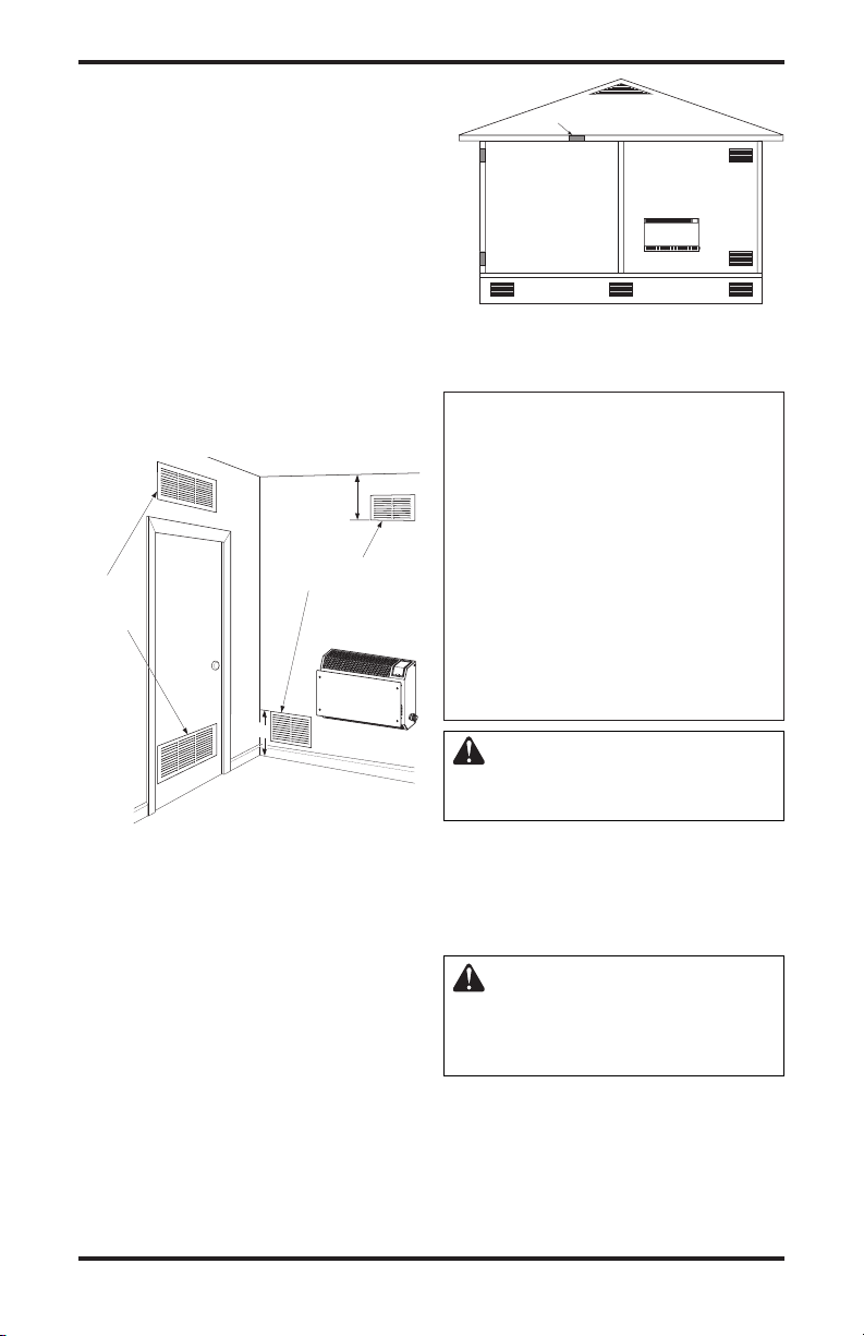
VENTILATION AIR
Ventilation Air From Inside Building
This fresh air would come from an adjoining un
confined space. When ventilating to an adjoining
unconfined space, you must provide two permanent openings: one within 12" (30.4 cm) of the
ceiling and one within 12" (30.4 cm) of the floor
on the wall connecting the two spaces (see options
1 and 2, Figure 2). You can also remove door into
adjoining room (see option 3, Figure 2). Follow the
National Fuel Gas Code, ANSI Z223.1/NFPA 54,
Section 5.3, Air for Combustion and Ventilation for
required size of ventilation grills or ducts.
-
Figure 3 - Ventilation Air from Outdoors
INSTALLATION
NOTICE: This heater is intended
for use as supplemental heat.
Use this heater along with your
primary heating system. Do not
install this heater as your primary heat source. If you have a
central heating system, you may
run system’s circulating blower
while using heater. This will help
circulate the heat throughout the
house. In the event of a power
outage, you can use this heater
as your primary heat source.
WARNING: A qualified service person must install heater.
Follow all local codes.
Figure 2 - Ventilation Air from Inside
Building
Ventilation Air From Outdoors
Provide extra fresh air by using ventilation grills
or ducts. You must provide two permanent openings: one within 12" (30.4 cm) of the ceiling and
one within 12" (30.4 cm) of the floor. Connect
these items directly to the outdoors or spaces
open to the outdoors. These spaces include attics
and crawl spaces. Follow the National Fuel Gas
Code, ANSI Z223.1/NFPA 54, Section 5.3, Air for
Combustion and Ventilation for required size of
ventilation grills or ducts.
IMPORTANT: Do not provide openings for inlet
or outlet air into attic if attic has a thermostatcontrolled power vent. Heated air entering the attic
will activate the power vent.
116292-01D 7
www.desatech.com
CHECK GAS TYPE
Use only the correct type of gas (natural or propane/LP). If your gas supply is not the correct gas
type, do not install heater. Call dealer where you
bought heater for proper type heater.
WARNING: This appliance
is equipped for (natural or pro
pane/LP) gas. Field conversion
is not permitted.
-
INSTALLATION
Continued
INSTALLATION ITEMS
Before installing heater, make sure you have the
items listed below.
• for propane/LP gas, external regulator (supplied
by installer)
• piping (check local codes)
• sealant (resistant to propane/LP gas)
• equipment shutoff valve *
• ground joint union
• sediment trap
• tee joint
• pipe wrench
• for natural gas, test gauge connection*
* A CSA design-certified equipment shutoff valve
with 1/8" NPT tap is an acceptable alternative to
test gauge connection. The optional CSA designcertified equipment shutoff valve can be purchased
from your dealer. See
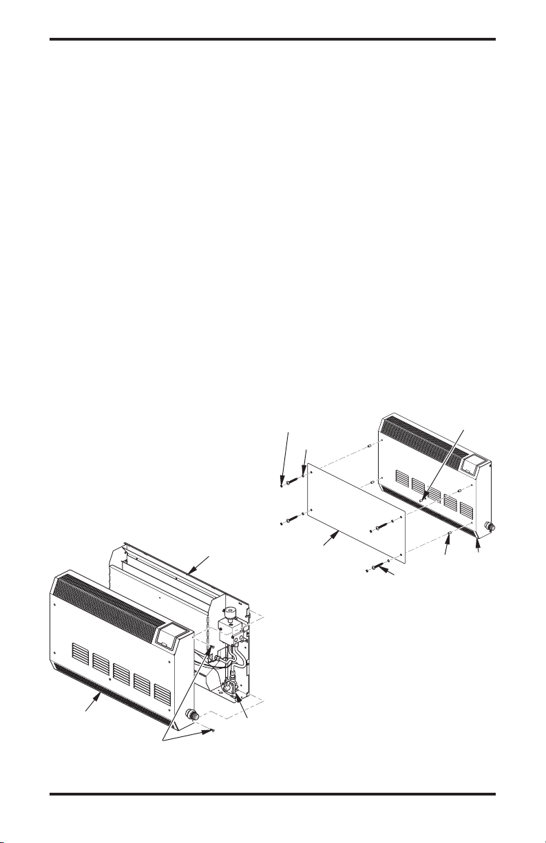
REMOVING FRONT PANEL OF
HEATER
1. Remove and discard shipping screw from back
panel of heater (see Figure 4).
2. Remove the four screws, two on each side of
front panel. Set aside.
3. Pull front panel forward from the bottom, then
lift panel up to remove. If ignitor is installed,
pull front panel forward only 2" to 3" (5 to 7.6
cm) away from back panel. Reach into lower
right side of heater and disconnect ignitor
wire. Set front panel aside.
4. Remove any remaining packaging materials.
Accessories, page 23.
Shipping
Screw
Location
Installing Glass Panel
Items needed from hardware packet:
1 - Bushing
4 - Black spacers
4 - Retaining clips
4 - 1.5" long screws
4 - Screw covers
1. Locate hardware packet and dark acrylic glass.
2.
Peel protective coating from both sides of glass.
3. Snap bushing into center front hole of front
panel (see Figure 5).
4. Turn front panel face down. Gently press onto
a hard surface to snap bushing into hole. Turn
panel back over, face up.
5. Place spacers over 4 holes on front panel as
shown in Figure 5.
6. Position glass on top of spacers, aligning holes.
Note: If glass gets scratched or marred from
normal use, it may be reversed on heater.
7. Place 4 retaining clips on glass over holes.
8. Install screws in each hole, but do not tighten
at this time.
9. Square glass up with top front surface of front
panel. Tighten screws.
10. Snap screw covers over retaining clips.
Spacer
Bushing
Front
Panel
Screw Cover
Retainer Clip
Glass Panel
Screw
Figure 5 - Installing Glass Panel
Front Panel
Screw
Figure 4 - Removing Front Panel Of Heater
8
Ignitor
Wire
www.desatech.com
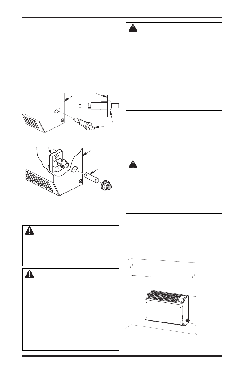
INSTALLING IGNITOR
Locate ignitor in hardware bag. Determine if
1.
your heater is equipped with piezo ignitor or an
electronic ignitor (see Figures 6 and 7, page 9.
2. For Piezo Ignitor, snap ignitor into hole
located on right side of heater as shown in
Figure 6, page 9.
3. For Electronic Ignitor, install ignitor through
hole located on right side of heater as shown
in Figure 7, page 9.
116292-01D
INSTALLATION
Minimum
From
Sides Of
Heater
36"
(91.4 cm)
Minimum
2" (5.1 cm)
FLOOR
CEILING
Minimum To
To
p Surface
Of Carpeting,
Ti
le Or Other
Combustible
Material
Left
Side
Right
Side
6" (15.2 cm)
Side View
Continued
4. For both ignitors, install ignitor wire only
when replacing front panel of heater after
connecting to gas supply and checking gas
connections (see pages 11 through 13). With
bottom of front panel only 2" to 3" (5 to 7.6
cm) away from back panel, reach into lower
right corner of heater to connect ignitor wire
to ignitor terminal (see Figure 4, page 8).
Right Side
of Heater
Piezo
Ignitor
Figure 6 - Installing Piezo Ignitor
Electronic Ignitor
Right Side
of Heater
CAUTION: This heater creates warm air currents. These
currents move heat to wall surfaces next to heater. Installing
heater next to vinyl or cloth wall
coverings or operating heater
where impurities (such as, but
not limited to, tobacco smoke,
aromatic candles, cleaning fluids, oil or kerosene lamps, etc.) in
the air exist, may discolor walls
or cause odors.
IMPORTANT: Vent-free heaters add moisture to
the air. Although this is beneficial, installing heater
in rooms without enough ventilation air may cause
mildew to form from too much moisture. See Air
for Combustion and Ventilation, page 5. If high hu
midity is experienced, a dehumidifier may be used
to help lower the water vapor content in the air.
-
Battery
CAUTION: If you install the
heater in a home garage
• heater pilot and burner must
be at least 18" (45.7 cm) above
floor
Figure 7 - Installing Electronic Ignitor
• locate heater where moving
vehicle will not hit it
LOCATING HEATER
This heater is designed to be mounted on a wall.
WARNING: Maintain the
minimum clearances shown
in Figure 8. If you can, provide
greater clearances from floor,
For convenience and efficiency, install heater
• where there is easy access for operation, inspec
tion and service
• in coldest part of room
Locate heater near a 120V 60Hz electrical outlet
(normal household voltage).
ceiling and joining wall.
WARNING: Never install the
heater
• in a bathroom or a bedroom
• in a recreational vehicle
•
where curtains, furniture, clothing or other flammable objects
are less than 36" (92 cm) from the
front, top or sides of the heater
• as a fireplace insert
• in high traffic areas
• in windy or drafty areas
116292-01D 9
Figure 8 - Mounting Clearances As
Viewed From Front of Heater
www.desatech.com
-
INSTALLATION
13" (33 cm)
11"
(27.9 cm)
Min.
12"
(30.4
cm)
Min.
Ad j o in ing Wa l l
Only Insert Mounting
Screws Through Last
Hole On Each End
Floor
Continued
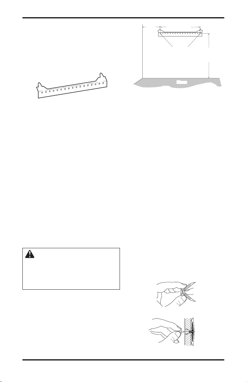
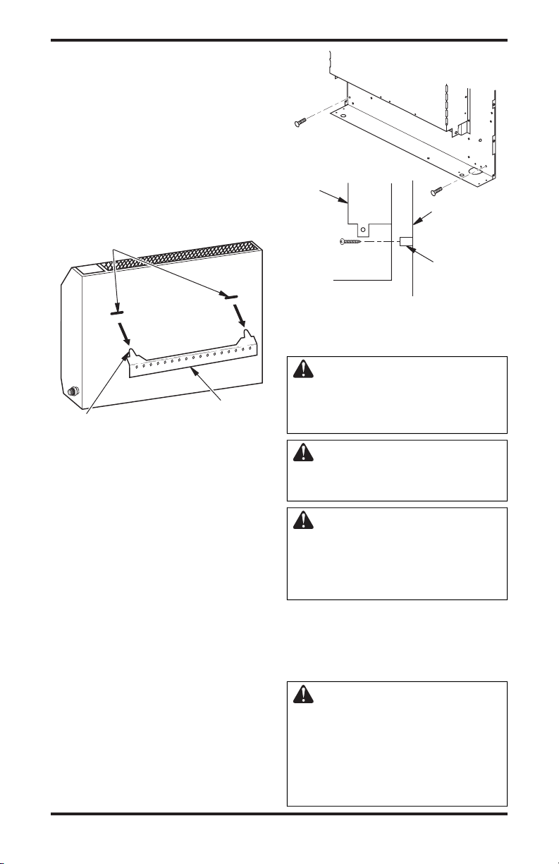
INSTALLING HEATER TO WALL
Mounting Bracket
Locate mounting bracket that has been taped to
back panel of heater for shipping. Remove mounting bracket from back panel of heater.
Figure 9 - Mounting Bracket
Methods For Attaching Mounting Bracket
To Wall
Only use last hole on each end of mounting bracket
to attach bracket to wall. These two holes centers are
13" (33 cm) apart. Attach mounting bracket to wall
in one of two ways:
1. Attaching to wall stud
2. Attaching to wall anchor
Attaching to Wall Stud: This method provides the
strongest hold. Insert mounting screws through
mounting bracket and into wall studs.
Attaching to Wall Anchor: This method allows you
to attach mounting bracket to hollow walls (wall
areas between studs) or to solid walls (concrete
or masonry).
Decide which method better suits your needs.
Either method will provide a secure hold for the
mounting bracket.
Marking Screw Locations
1. Tape mounting bracket to wall where heater
will be located. Make sure mounting bracket
is level.
WARNING: Maintain mini-
mum clearances shown in Figure
10. If you can, provide greater
clearances from floor and joining wall.
2. Mark screw locations on wall (see Figure 10).
Note: Only mark last hole on each end of
mounting bracket. Insert mounting screws
through these holes only.
3. Remove tape and mounting bracket from
wall.
Attaching Mounting Bracket To Wall
Note:
Wall anchors, mounting screws and spacers
are in hardware package. The hardware package
is provided with heater.
10
Figure 10 - Mounting Bracket Clearances
Attaching To Wall Stud Method
For attaching mounting bracket to wall studs
1. Drill holes at marked locations using 9/64"
drill bit.
2. Place mounting bracket onto wall. Line up last
hole on each end of bracket with holes drilled
in wall.
3. Insert mounting screws through bracket and
into wall studs.
4. Tighten screws until mounting bracket is
firmly fastened to wall studs.
Attaching To Wall Anchor Method
For attaching mounting bracket to hollow walls
(wall areas between studs) or solid walls (concrete
or masonry)
1. Drill holes at marked locations using 5/16"
drill bit. For solid walls (concrete or masonry),
drill at least 1" deep.
2. Fold wall anchor as shown in Figure 11.
3. Insert wall anchor (wings first) into hole. Tap
anchor flush to wall.
4. For thin walls [1/2" (1.3 cm) or less], insert red
key into wall anchor. Push red key to “pop” open
anchor wings. IMPORTANT:
key! For thick walls [over 1/2" (1.3 cm) thick]
or solid walls, do not pop open wings.
5. Place mounting bracket onto wall. Line up
last hole on each end of bracket with wall
anchors.
Figure 12 - Popping Open Anchor Wings
www.desatech.com
Do not hammer
Figure 11 - Folding Anchor
For Thin Walls
116292-01D
Side View
Front View
INSTALLATION
Continued
6. Insert mounting screws through bracket and
into wall anchors.
7. Tighten screws until mounting bracket is
firmly fastened to wall.
Placing Heater On Mounting Bracket
1. Locate two horizontal slots on back panel of
heater.
2. Place heater onto mounting bracket. Slide
horizontal slots onto stand-out tabs on mount
ing bracket.
Horizontal Slots
Heater
-
Wall
Spacer
Figure 14 - Installing Bottom Mounting
Screws
CONNECTING TO GAS SUPPLY
WARNING: This appliance
requires a 3/8" NPT (National
Stand-Out Tab
Figure 13 - Mounting Heater Onto
Mounting Bracket
Installing Bottom Mounting Screws
1. Locate two bottom mounting holes. These
holes are near bottom on back panel of heater
(see Figure 14).
2. Mark screw locations on wall.
3. Remove heater from mounting bracket.
4. If installing bottom mounting screws into
hollow or solid wall, install wall anchors.
Follow steps 1 through 4 under Attaching To
Wall Anchor Method
If installing bottom mounting screw into wall
stud, drill holes at marked locations using
9/64" drill bit.
5. Replace heater onto mounting bracket.
6. Place spacers between bottom mounting holes
and wall anchor or drilled hole.
7. Hold spacer in place with one hand. With other
hand, insert mounting screw through bottom
mounting hole and spacer. Place tip of screw
in opening of wall anchor or drilled hole.
8. Tighten both screws until heater is firmly
secured to wall. Do not over tighten.
Note: Do not replace front panel at this time.
Replace front panel after making gas connections and checking for leaks.
116292-01D 11
Mounting Bracket
(attached to wall)
, page 10.
www.desatech.com
Pipe Thread) inlet connection to
the pressure regulator.
WARNING: A qualified service
person must connect heater to gas
supply. Follow all local codes.
WARNING: For natural
gas, never connect heater to
private (non-utility) gas wells.
This gas is commonly known
as wellhead gas.
IMPORTANT: For natural gas, check gas line
pressure before connecting heater to gas line. Gas
line pressure must be no greater than 10.5" of wa
ter. If gas line pressure is higher, heater regulator
damage could occur.
CAUTION: For propane/LP
gas, never connect heater directly to the propane/LP supply.
This heater requires an external
regulator (not supplied). Install
the external regulator between the
heater and propane/LP supply.
-
INSTALLATION
Continued
For propane/LP gas, the installer must supply an
external regulator. The external regulator will
reduce incoming gas pressure. You must reduce
incoming gas pressure to between 11 and 14 inches
of water. If you do not reduce incoming gas pres
sure, heater regulator damage could occur. Install
the external regulator with the vent pointing down
as shown in Figure 15. Pointing the vent down
protects it from freezing rain or sleet.
CAUTION: Use only new,
black iron or steel pipe. Inter
nally-tinned copper tubing may
be used in certain areas. Check
your local codes. Use pipe of
large enough diameter to allow
proper gas volume to heater. If
pipe is too small, undue loss of
volume will occur.
Typical Inlet Pipe Diameter - 3/8" (9.5 mm) or
greater
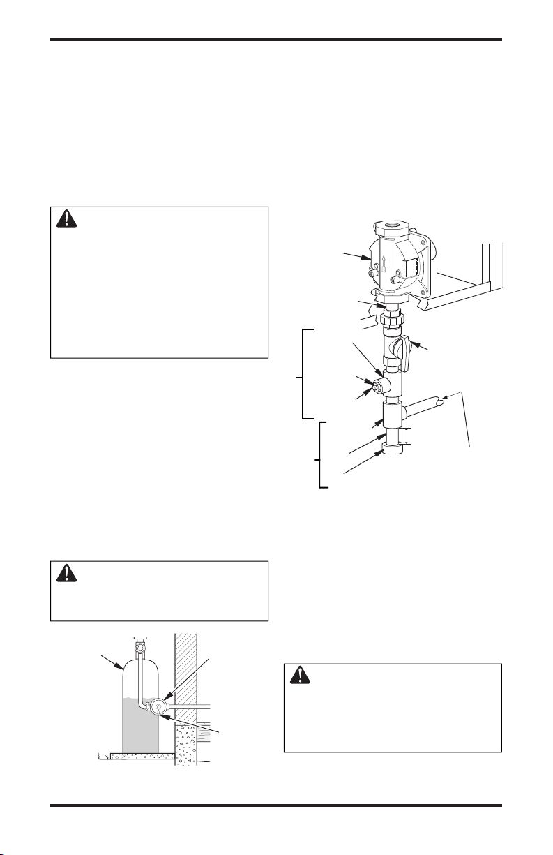
Installation must include equipment shutoff valve,
union and plugged 1/8" NPT tap. Locate NPT tap
within reach for test gauge hook up. NPT tap must
be upstream from heater (see Figure 16).
IMPORTANT: Install an equipment shutoff valve
in an accessible location. The equipment shutoff
valve is for turning on or shutting off the gas to
the appliance.
Apply pipe joint sealant lightly to male NPT
threads. This will prevent excess sealant from
going into pipe. Excess sealant in pipe could result
in clogged heater valves.
WARNING: Use pipe joint
sealant that is resistant to liquid
petroleum (LP) gas.
Propane/LP
Supply Tank
External
Regulator
-
Vent
Pointing
Down
Install sediment trap in supply line as shown in
Figure 16. Locate sediment trap where it is within
reach for cleaning. Locate sediment trap where
trapped matter is not likely to freeze. A sediment
trap traps moisture and contaminants. This keeps
them from going into heater controls. If sediment
trap is not installed or is installed wrong, heater
may not run properly.
IMPORTANT: Hold the pressure regulator with
wrench when connecting it to gas piping and/or
fittings. Do not over tighten pipe connection to
regulator. The regulator body could be damaged.
Pressure
Regulator
3/8" NPT
Pipe Nipple
Tee Joint
Reducer
Bushing to
1/8" NPT
1/8" NPT
Plug Tap
Test Gauge Connection*
Tee Joint
Pipe
Nipple
Cap
Sediment Trap
Figure 16 - Gas Connection
* A CSA design-certified equipment shutoff valve
with 1/8" NPT tap is an acceptable alternative to
test gauge connection. Purchase the optional CSA
design-certified equipment shutoff valve from your
dealer. See
Accessories, page 23.
From Gas Meter (4" W.C.
to 10.5" W.C. Pressure)
From External Regulator
(11" W.C. to 14" W.C.
Heater
Cabinet
Equipment
Shutoff
Valve *
3"
(7.6 cm)
Min.
Natural Gas
Propane/LP
Pressure)
CHECKING GAS CONNECTIONS
WARNING: Test all gas piping
and connections, internal and
external to unit, for leaks after
installing or servicing. Correct
all leaks at once.
Figure 15 - External Regulator With Vent
12
Pointing Down
www.desatech.com
116292-01D

INSTALLATION
Continued
WARNING: Never use an open
flame to check for a leak. Apply a
noncorrosive leak detection fluid
to all joints. Bubbles forming show
a leak. Correct all leaks at once.
CAUTION: For propane/LP
gas, make sure external regula
tor has been installed between
propane/LP supply and heater.
See guidelines under Connect-
ing to Gas Supply, page 11.
PRESSURE TESTING GAS SUPPLY
PIPING SYSTEM
Test Pressures In Excess Of 1/2 PSIG
(3.5 kPa)
1. Disconnect appliance with its appliance main
gas valve (control valve) and equipment
shutoff valve from gas supply piping system.
Pressures in excess of 1/2 psig will damage
heater regulator.
2. Cap off open end of gas pipe where equipment
shutoff valve was connected.
3. Pressurize supply piping system by either
opening propane/LP supply tank valve for
propane/LP gas or opening main gas valve
located on or near gas meter for natural gas
or using compressed air.
4. Check all joints of gas supply piping system.
Apply a noncorrosive leak detection fluid to
all joints. Bubbles forming show a leak.
5. Correct all leaks at once.
6. Reconnect heater and equipment shutoff
valve to gas supply. Check reconnected fittings for leaks.
Test Pressures Equal To or Less Than 1/2
PSIG (3.5 kPa)
1. Close equipment shutoff valve (see Figure 17).
2. Pressurize supply piping system by either
opening propane/LP supply tank valve for
propane/LP gas or opening main gas valve
located on or near gas meter for natural gas
or using compressed air.
3. Check all joints from gas meter for natural gas
(see Figure 18) or propane/LP supply tank for
propane/LP gas, to equipment shutoff valve
(see Figure 19). Apply a noncorrosive leak
detection fluid to all joints. Bubbles forming
show a leak.
4. Correct all leaks at once.
116292-01D 13
www.desatech.com
PRESSURE TESTING HEATER GAS
CONNECTIONS
1. Open equipment shutoff valve (see Figure 17).
2. For natural gas open main gas valve located
on or near gas meter. For propane/LP gas open
propane/LP supply tank valve.
3. Make sure control knob of heater is in the OFF
position.
4. Check all joints from equipment shutoff valve
to thermostat gas valve (see Figure 18 or 19).
Apply a noncorrosive leak detection fluid to
all joints. Bubbles forming show a leak.
5. Correct all leaks at once.
-
6. Light heater (see Operating Heater, page 14).
Check all other internal joints for leaks.
7. Turn off heater (see To Turn Off Gas to Appli-
ance, page 15).
8. Connect ignitor wire and replace front panel.
Equipment
Shutoff Valve
Figure 17 - Equipment Shutoff Valve
Gas
Meter
Equipment
Shutoff Valve
Figure 18 - Checking Gas Joints for
Propane/LP
Supply Tank
Figure 19 - Checking Gas Joints for
Natural Gas
Equipment
Shutoff Valve
Propane/LP Gas
Open
Closed
INSTALLATION
Continued
CONNECTING TO ELECTRICAL
SUPPLY
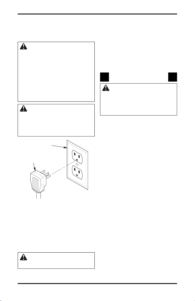
WARNING: Fan accessory
must be grounded. Fan comes
with a three-prong, grounding
plug as shown in Figure 20. The
plug is your protection against
electrical shock. Plug it into a
standard, three-hole, grounded,
outlet. If cord needs replacing,
use only a cord with a threeprong, grounding plug.
CAUTION: Label all wires
prior to disconnection when
servicing controls. Wiring errors
can cause improper and danger
ous operation (see page 22).
Grounded Outlet
Grounding Plug
Figure 20 - Grounding Plug
EXTENSION CORD
Use extension cord if needed. The cord must have
a three-prong, grounding plug and a three-hole re
ceptacle. Make sure cord is in good shape. It must
be heavy enough to carry the current needed. An
undersized cord will cause a drop in line voltage.
This will result in loss of power and overheating.
Use a No. 16 AWG cord for lengths less than 50
feet (15.24 m) .
CAUTION: Verify proper operation after servicing.
-
Operating Fan
The blower is connected to a thermostat. When unit
heats up, the fan will operate. A few minutes after
unit cycles off or is turned off, the fan will shut
off. The fan will cycle on and off in this manner.
Note: If you have a heater with a thermostat, the
heater and fan will not turn off and on at exactly
the same time. Fan cycle times will vary with the
heat setting selected.
OPERATING HEATER
FOR YOUR SAFETY READ
BEFORE LIGHTING
WARNING: If you do not follow these instructions exactly,
a fire or explosion may result
causing property damage, personal injury or loss of life.
A. This appliance has a pilot which must be
lighted by hand. When lighting the pilot,
follow these instructions exactly.
B. BEFORE LIGHTING smell all around the
appliance area for gas. Be sure to smell next
to the floor because some gas is heavier than
air and will settle on the floor.
WHAT TO DO IF YOU SMELL GAS
• Do not try to light any appliance.
• Do not touch any electric switch; do not
use any phone in your building.
• Immediately call your gas supplier from
a neighborʼs phone. Follow the gas
supplierʼs instructions.
• If you cannot reach your gas supplier,
call the fire department.
C. Use only your hand to push in or turn the
gas control knob. Never use tools. If the
knob will not push in or turn by hand,
donʼt try to repair it, call a qualified service
technician. Force or attempted repair may
-
result in a fire or explosion.
D. Do not use this appliance if any part has
been under water. Immediately call a
qualified service technician to inspect the
appliance and to replace any part of the
control system and any gas control which
has been under water.
14
www.desatech.com
116292-01D
O
F
F
P
I
L
O
T
OPERATING HEATER
OFF
O
F
F
P
I
L
O
T
Continued
LIGHTING
INSTRUCTIONS
CAUTION: Do not try to adjust heating levels by using the
equipment shutoff valve.
1. STOP! Read the safety information, page 14.
2. Make sure equipment shutoff valve is fully
open.
3. Turn off any electric power to the appliance
if service is to be performed.
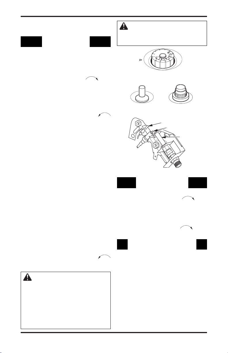
4. Turn control knob clockwise to the
OFF position.
Figure 21 - Control Knob In The OFF
Position
5. Wait five minutes to clear out any gas. Then
smell for gas, including near the floor. If you
smell gas, STOP! Follow “B” in the safety
information, page 14. If you donʼt smell gas,
go to the next step.
6. Turn control knob counterclockwise
to the PILOT position. Press in control
knob for five (5) seconds.
7.
With control knob pressed in, push down and
release ignitor button. This will light pilot.
Piezo Ignitor
Figure 22 - Ignitor Buttons
Electronic Ignitor
Thermocouple
Ignitor Electrode
Pilot Burner
The pilot is attached to the front of burner.
Note: You may be running this heater for the
first time after hooking up to gas supply. If so,
you may need to press in control knob for 30
seconds or more. This will allow air to bleed
from the gas system. If needed, keep pressing
ignitor button until pilot lights. If ignitor does
not light pilot, refer to Troubleshooting, page
18 or contact a qualified service person or gas
supplier for repairs. Until repairs are made,
light pilot with match. To light pilot with match,
see Manual Lighting Procedure, page 16.
8. Keep control knob pressed in for 30 seconds
after lighting pilot. After 30 seconds, release
control knob.
• If control knob does not pop up when re-
leased, contact a qualified service person
or gas supplier for repairs.
Note: If pilot goes out, repeat steps 4 thru 7.
Thermostat models have a safety interlock
system. Wait one (1) minute before lighting
pilot again.
9. Turn control knob counterclockwise
to desired heating level. The main burner
should light.
WARNING: Always operate
manual control heaters at the
locked positions. Operation
between these positions may
create a possible health hazard
if used in a poorly ventilated
room. Read owner’s manual for
complete instructions.
116292-01D 15
www.desatech.com
Figure 23 - Pilot (actual pilot may vary)
TO TURN OFF GAS
TO APPLIANCE
Shutting Off Heater
1. Turn control knob clockwise
to the
OFF position.
2. Turn off all electric power to the appliance
if service is to be performed.
Shutting Off Burner Only (pilot stays lit)
Turn control knob clockwise to the
PILOT position.
THERMOSTAT CONTROL
OPERATION
The thermostatic control used on these models
differs from standard thermostats. Standard
thermostats simply turn on and off the burner.
The thermostat used on this heater senses the
room temperature. The thermostat adjusts the
amount of gas flow to the burner. This increases
or decreases the burner flame height. At times
the room may exceed the set temperature. If so,
the burner will shut off. The burner will cycle
back on when room temperature drops below the
set temperature. The control knob can be set to
any heat level between 1 and 5. Selecting the 5
setting will cause the burner to remain fully on
without modulating down in most cases.
OPERATING HEATER
Continued
Note: The thermostat sensing bulb measures
the temperature of air near the heater cabinet.
This may not always agree with room temperature (depending on housing construction,
installation location, room size, open air tem
peratures, etc.). Frequent use of your heater will
let you determine your own comfort levels.
MANUAL LIGHTING
PROCEDURE
1. Remove front panel (see Figure 4, page 8).
2. Follow steps 1 through 7 under Lighting
Instructions, page 15.
3. With control knob pressed in, strike match.
Hold match to pilot until pilot lights.
4. Keep control knob pressed in for 30 seconds
after lighting pilot. After 30 seconds, release
control knob. Now follow step 9, under
Lighting Instructions, page 15.
5. Replace front panel.
INSPECTING HEATER
Check pilot flame pattern and burner flame pattern often.
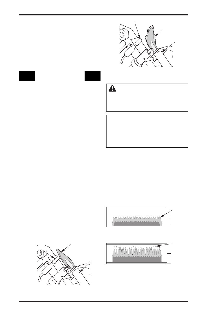
PILOT FLAME PATTERN
Figure 24 shows a correct pilot flame pattern.
Figure 25 shows an incorrect pilot flame pattern.
The incorrect pilot flame is not touching the
thermocouple. This will cause the thermocouple
to cool. When the thermocouple cools, the heater
will shut down.
If pilot flame pattern is incorrect, as shown in
Figure 25
•
turn heater off (see To Turn Off Gas to Appliance,
page 15)
• see Troubleshooting, page 18
Note: The pilot flame on natural gas units will
have a slight curve, but flame should be blue and
have no yellow or orange color.
Thermocouple
Blue Flame
Pilot
Burner
Thermocouple
Yellow Flame
-
Figure 25 - Incorrect Pilot Flame Pattern
BURNER FLAME PATTERN
WARNING: If yellow tipping
occurs, your heater could produce increased levels of carbon
monoxide.
NOTICE: Do not mistake orange
flames with yellow tipping. Dirt
or other fine particles enter the
heater and burn causing brief
patches of orange flame.
Figure 26 shows a correct burner flame pattern.
Figure 27 shows an incorrect burner flame pattern.
The incorrect burner flame pattern shows yellow
tipping of the flame. It also shows the flame higher
than 1/2 the deflector panel height.
If burner flame pattern is incorrect, as shown in
Figure 27
• turn heater off (see To Turn Off Gas To Appli
ance, page 15)
• see Troubleshooting
Figure 26 - Correct Burner Flame Pattern
Figure 27 - Incorrect Burner Flame
, page 18
Pattern
Pilot
Burner
Blue
Flame
1
/2
Deflector
Height
Yellow
Tipping
1
2
/
Deflector
Height
-
Figure 24 - Correct Pilot Flame Pattern
16
www.desatech.com
116292-01D

CLEANING AND
MAINTENANCE
WARNING: Turn off heater
and let cool before cleaning.
CAUTION: You must keep
control areas, burner and circulating air passageways of heater
clean. Inspect these areas of
heater before each use. Have
heater inspected yearly by a
qualified service person. Heater
may need more frequent cleaning due to excessive lint from
carpeting, bedding material, pet
hair, etc.
WARNING: Failure to keep
the primary air opening(s) of
the burner(s) clean may result in
sooting and property damage.
ODS/PILOT AND BURNER
Use a vacuum cleaner, pressurized air or small,
soft bristled brush to clean.
BURNER PILOT AIR INLET
The primary air inlet holes allow the proper
amount of air to mix with the gas. This provides a
clean burning flame. Keep these holes clear of dust,
dirt and lint. Clean these air inlet holes prior to each
heating season. Blocked air holes will create soot.
We recommend that you clean the unit every three
months during operation and have heater inspected
yearly by a qualified service person.
We also recommend that you keep the burner
tube and pilot assembly clean and free of dust and
dirt. To clean these parts we recommend using
compressed air no greater than 30 PSI. Your local
computer store, hardware store or home center
may carry compressed air in a can. You can use a
vacuum cleaner in the blow position. If using com
pressed air in a can, please follow the directions on
the can. If you don't follow directions on the can,
you could damage the pilot assembly.
1. Shut off the unit, including the pilot. Allow
the unit to cool for at least thirty minutes.
2. Inspect burner, pilot for dust and dirt.
3. Blow air through the ports/slots and holes in
the burner.
4. Never insert objects into the pilot tube.
Clean the pilot assembly also. A yellow tip on the
pilot flame indicates dust and dirt in the pilot as
sembly. There is a small pilot air inlet about two
inches from where the pilot flame comes out of
the pilot assembly (see Figure 28). With the unit
off, lightly blow air through the air inlet. You may
blow through a drinking straw if compressed air
is not available.
Pilot Assembly
Pilot Air Inlet
Figure 28 - Pilot Inlet Air - Propane/LP
Pilot Shown (Actual Pilot May Vary from
Illustration)
CABINET
Air Passageways
Use a vacuum cleaner or pressurized air to clean.
Exterior and Dark Acrylic Front Glass
Use a soft cloth dampened with a mild soap and
water mixture. Wipe the cabinet to remove dust.
-
-
116292-01D 17
www.desatech.com

TROUBLESHOOTING
WARNING: Turn off and unplug heater and let cool before servicing.
Only a qualified service person should service and repair heater.
CAUTION: Never use a wire, needle or similar object to clean
ODS/pilot. This can damage ODS/pilot unit.
Note: All troubleshooting items are listed in order of operation.
OBSERVED PROBLEM
When ignitor button is pressed,
there is no spark at ODS/pilot
When ignitor button is pressed,
there is spark at ODS/pilot but
no ignition
POSSIBLE CAUSE
1. Ignitor electrode positioned
wrong
2. Ignitor electrode broken
3. Ignitor electrode not connected to ignitor cable
4. Ignitor cable pinched or wet
5. Broken ignitor cable
6. Bad ignitor
1. Gas supply turned off or equipment shutoff valve closed
2. Control knob not in PILOT
position
3. Control knob not pressed in
while in PILOT position
4. Air in gas lines when in
stalled
5. Depleted gas supply (propane/
LP gas only)
6. ODS/pilot is clogged
7. Gas regulator setting is not
correct
REMEDY
1. Replace pilot assembly
2. Replace pilot assembly
3. Reconnect ignitor cable
4. Free ignitor cable if pinched
by any metal or tubing. Keep
ignitor cable dry
5. Replace ignitor cable
6. Replace ignitor
1. Turn on gas supply or open
equipment shutoff valve
2. Turn control knob to PILOT
position
3. Press in control knob while in
PILOT position
-
4. Continue holding down con
trol knob. Repeat igniting op
eration until air is removed
5. Contact local propane/LP gas
company
6. Clean ODS/pilot (see Cleaning
and Maintenance, page 17) or
replace ODS/pilot assembly
7. Replace gas regulator
-
-
18
www.desatech.com
116292-01D

OBSERVED PROBLEM
ODS/pilot lights but flame
goes out when control knob is
released
TROUBLESHOOTING
Continued
POSSIBLE CAUSE
1.
Control knob not fully pressed in
2. Control knob not pressed in
long enough
3. Safety interlock system has
been triggered
4. Equipment shutoff valve not
fully open
5. Thermocouple connection
loose at control valve
6. Pilot flame not touching ther
mocouple, which allows ther
mocouple to cool, causing
pilot flame to go out. This
problem could be caused by
one or both of the following:
A) Low gas pressure
B) Dirty or partially clogged
ODS/pilot
7. Thermocouple damaged
8. Control valve damaged
-
-
REMEDY
1. Press in control knob fully
2. After ODS/pilot lights, keep
control knob pressed in 30
seconds
3. Wait one minute for safety in
terlock system to reset. Repeat
ignition operation
4. Fully open equipment shutoff
valve
5. Hand tighten until snug, then
tighten 1/4 turn more
6. A) Contact local natural or
propane/LP gas company
B) Cl ean ODS/pilot (se e
Cleaning and Maintenance
page 17) or replace ODS/pilot
assembly
7. Replace pilot assembly
8. Replace control valve
-
,
Burner does not light after
ODS/pilot is lit
Delayed ignition of burner
Burner backfiring during com
bustion
116292-01D 19
1. Burner orifice is clogged
2. Inlet gas pressure is too low
1. Manifold pressure is too low
2. Burner orifice is clogged
-
1. Burner orifice is clogged or
damaged
2. Burner damaged
3. Gas regulator defective
www.desatech.com
1. Clean burner (see Cleaning
and Maintenance, page 17)
or replace burner orifice
2. Contact local natural or pro
pane/LP gas company
1. Contact local natural or pro
pane/LP gas company
2. Clean burner (see Cleaning
and Maintenance, page 17)
or replace burner orifice
1. Clean burner (see Cleaning
and Maintenance, page 17)
or replace burner orifice
2. Replace burner
3. Replace gas regulator
-
-

OBSERVED PROBLEM
Yellow flame during burner
combustion
TROUBLESHOOTING
Continued
POSSIBLE CAUSE
1. Not enough air
2. Gas regulator defective
3. Clogged or dirty burner
REMEDY
1. Check burner for dirt and
debris. If found, clean burner
(see Cleaning and Mainte-
nance, page 17)
2. Replace gas regulator
3. Clean burner (see Cleaning
and Maintenance, page 17)
Slight smoke or odor during
initial operation
Heater produces a whistling
noise when burner is lit
White powder residue forming
within burner box or on adjacent
walls or furniture
Blower fan does not come on
Heater produces a clicking/ticking noise just after burner is lit
or shut off
1. Residues from manufacturing
processes
1. Turning control knob to 5
position when burner is cold
2. Air in gas line
3. Air passageways on heater
blocked
4. Dirty or partially clogged
burner orifice
1. When heated, vapors from
furniture polish, wax, carpet
cleaners, etc. may turn into
white powder residue
1. Power cord not connected
2. No power to electric outlet
3. Time delay for thermal switch
to warm up
4. Bad switch
5. Loose wire connection
1. Metal expanding while heat
in g or contra c ting while
cooling
1. Problem will stop after a few
hours of operation
1. Turn control knob to 1 posi
tion and let warm up for a
minute
2. Operate burner until air is
removed from line. Have gas
line checked by local natural
or propane/LP gas company
3. Observe minimum installation
clearances (see Figure 8, page 9)
4. Clean burner (see Cleaning
and Maintenance, page 17)
or replace burner orifice
1. Turn heater off when using
furniture polish, wax, carpet
cleaners or similar products
1. Connect power cord to 120V
60Hz outlet
2. Have a qualified service per
son check for power at outlet
3. Wait 4 to 5 minutes with the
burner on
4. Replace switch
5. Reconnect wires
1. This is common with most heat
ers. If noise is excessive, contact
qualified service person
-
-
-
20
www.desatech.com
116292-01D

TROUBLESHOOTING
Continued
WARNING: If you smell gas
• Shut off gas supply.
• Do not try to light any appliance.
• Do not touch any electrical switch; do not use any phone in your
building.
• Immediately call your gas supplier from a neighbor’s phone. Follow the gas supplier’s instructions.
• If you cannot reach your gas supplier, call the fire department.
IMPORTANT: Operating heater where impurities in air exist may create odors. Cleaning supplies,
paint, paint remover, cigarette smoke, cements and glues, new carpet or textiles, etc., create fumes.
These fumes may mix with combustion air and create odors.
OBSERVED PROBLEM
Heater produ ces unwanted
odors
Heater shuts off in use (ODS
operates)
Gas odor even when control knob
is in OFF position
Gas odor during combustion
Moisture/condensation noticed
on windows
POSSIBLE CAUSE
1. Heater burning vapors from
paint, hair spray, glues, etc.
(see IMPORTANT statement
above)
2. Low fuel supply (propane/LP
gas only)
3. Gas leak. See Warning state
ment above
1. Not enough fresh air is avail
able
2. Low line pressure
3. ODS/pilot is partially clogged
1. Gas leak. See Warning state
ment above
2. Control valve defective
1. Foreign matter between control
valve and burner
2. Gas leak. See Warning state
ment above
1. Not enough combustion/venti
lation air
REMEDY
1. Ventilate room. Stop using
odor causing products while
heater is running
2. Refill supply tank
3. Locate and correct all leaks
(see Checking Gas Connec
-
tions, page 12)
1. Open window and/or door for
ventilation
2. Contact local natural or pro
pane/LP gas company
3. Clean ODS/pilot (see Cleaning
and Maintenance, page 17)
1. Locate and correct all leaks
-
(see Checking Gas Connec
tions, page 12)
2. Replace control valve
1. Take apart gas tubing and
remove foreign matter
2. Locate and correct all leaks
-
(see Checking Gas Connec
tions, page 12)
1. Refer to Air for Combustion
and Ventilation requirements
(page 5)
-
-
-
-
116292-01D 21
www.desatech.com

SPECIFICATIONS
Thermostat
Sensor Switch/
Interruptor de sensor
de temperatura
White/Blanco
Green/Verde
11
0/115
V.
A.C.
(V.C.A.)
Blower Motor/
Motor del
ventilador
Black/Negro
Black/
Negro
Thermostat
Sensor Switch/
Interruptor de sensor
de temperatura
N/O
* If any of the original wire as supplied with the appliance must be replaced,
it must be replaced with type 105°C wire or its equivalent.
* En caso que se deba reemplazar alguno de los cables suministrados
originalmente con el calentador, utilice únicamente cable tipo 105°C u otro equivalente.
Line/
Línea
Neutral/
Neutro
White/
Blanco
Green/
Verde
Motor
Black/
Negro
Black/
Negro
LSL18NT, SL18NT and VSL18NT
• Natural Gas
• 9,000/18,000 Btu/Hr (Variable)
• Piezo or Electronic Ignition
• Pressure Regulator Setting - 3" W.C.
• Inlet Gas Pressure* (in. of water)
Maximum - 10.5" Minimum - 4"
• Heater Weight - 23 lbs. (10.4 kg)
Shipping Weight - 28 lbs. (12.7 kg)
*For purposes of input adjustment
LSL18PT, SL18PT and VSL18PT
• Propane/LP Gas
• 9,000/18,000 Btu/Hr (Variable)
• Piezo or Electronic Ignition
• Pressure Regulator Setting - 10" W.C.
• Inlet Gas Pressure* (in. of water)
Maximum - 14" Minimum - 11"
• Heater Weight - 23 lbs. (10.4 kg)
Shipping Weight - 28 lbs. (12.7 kg)
*For purposes of input adjustment
WIRING DIAGRAMS
CAUTION: Label all wires prior to disconnection when servicing
controls. Wiring errors can cause improper and dangerous opera
tion. Verify proper operation after servicing.
-
Wiring Diagram
22
Electrical Ladder Diagram
www.desatech.com
116292-01D

ACCESSORIES
Purchase these heater accessories from your local
dealer. If they can not supply these accessories, either
contact your nearest Parts Central (see page 26) or
call DESA Heating Products at 1-866-672-6040
for referral information. You can also write to the
address listed on the back page of this manual.
EQUIPMENT SHUTOFF VALVE
GA5010
For all models. Equipment shutoff valve with
1/8" NPT tap.
ELECTRONIC IGNITOR KIT - GA435
Not Shown
For all piezo ignitor models. Provides easier
lighting of the pilot.
TECHNICAL SERVICE
You may have further questions about installation,
operation or troubleshooting. If so, contact DESA
Heating Productsʼ Technical Service Department
at 1-866-672-6040. When calling please have your
model and serial numbers of your heater ready.
You can also visit DESA Heating Productsʼ techni
cal service web site at www.desatech.com.
REPLACEMENT PARTS
Note: Use only original replacement parts. This
will protect your warranty coverage for parts
replaced under warranty.
PARTS UNDER WARRANTY
Contact authorized dealers of this product. If
they canʼt supply original replacement part(s),
call DESA Heating Productsʼ Technical Service
Department at 1-866-672-6040.
When calling DESA Heating Products, have
ready
• your name
• your address
• model and serial numbers of your heater
• how heater was malfunctioning
• type of gas used (propane/LP or natural gas)
• purchase date
Usually, we will ask you to return the part to the
factory.
PARTS NOT UNDER WARRANTY
Contact authorized dealers of this product. If they
canʼt supply original replacement part(s), either
contact your nearest Parts Central (see page 26)
or call DESA Heating Products at 1-866-672-6040
for referral information.
When calling DESA Heating Products, have
ready
• model number of your heater
-
• the replacement part number
SERVICE PUBLICATIONS
You can purchase a service manual from the address
listed on the back page of this manual. Send a check
for $5.00 payable to DESA Heating Products.
116292-01D 23
www.desatech.com
When Gas Pressure Is Too Low
• pilot will not stay lit
• burner will have delayed ignition
• heater will not produce specified heat
• propane/LP gas supply may be low
You may feel your gas pressure is too low. If
so, contact your local natural or propane/LP
gas supplier.
SERVICE HINTS

ILLUSTRATED PARTS BREAKDOWN
2
4
1
5
6
8
9
10
11
12
13
14
17
18
19
20
15
7
21
22
32
23
28
29
30
31
16
33
24
3
25
26
27
AA
Battery
Positive
UP
AAA
Battery
Negative
UP
MODELS LSL18NT, LSL18PT, SL18NT, SL18PT, VSL18NT AND VSL18PT
Install Battery According
To This Illustration
(Determine which
electronic ignitor your
heater uses)
24
www.desatech.com
116292-01D

PARTS LIST
This list contains replaceable parts used in your heater. When ordering parts, follow the instructions
listed under Replacement Parts on page 23 of this manual.
KEY
NO. PART NO. DESCRIPTION QTY.
1 116591-01DE Painted Screen • • • • • • 1
2 116958-01 Plastic Door & Housing • • • • • • 1
3 117471-01 Surround Shield • • • • • • 1
4 116667-01CK Front Panel • • • • • • 1
5 116392-01 Dark Acrylic Glass • • • • • • 1
6 097159-04 Piezo Ignitor • • 1
7 111435-01 Electronic Ignitor • • • • 1
8 M50104-06 Shorty Bushing • • • • • • 1
9 116276-01 Switch Mounting Bracket • • • • • • 1
10 103972-02 Thermostat Sensor Switch • • • • • • 1
11 116283-01
Fiber Panel • • • • • • 1
12 116544-01 Fiber Surround • • • • • • 1
13 116282-01 Burner, Natural Gas • • • 1
116282-02 Burner, Propane/LP Gas
14 116784-01 Radiation Shield • • • • • • 1
15 098249-01 ODS Pilot Nut • • • • • • 2
16 116280-01 Outlet Tube • • • • • • 1
17 110803-01 ODS Pilot, Natural • • • 1
110803-02
ODS Pilot, Propane/LP • • • 1
18 098271-09 Ignitor Cable • • 1
098271-11
Ignitor Cable • • • • 1
19 116679-01 Pilot Bracket • • • • • • 1
20 101004-08 Injector, Natural • • • 1
101004-10 Injector, Propane/LP • • • 1
21 097785-11 Gasket • • • • • • 1
22 116528-01 Lower Blower Duct • • • • • • 1
23 116286-01 Blower • • • • • • 1
24 116529-01 Upper Blower Duct • • • • • • 1
25 116270-01 Top Baffle • • • • • • 1
26 099066-02 Mounting Bracket • • • • • • 1
27 116267-01 Back Panel • • • • • • 1
28 M11143-1 Strain Relief Bushing • • • • • • 1
29 098522-28 Gas Valve, Natural • • • 1
098522-11 Gas Valve, Propane/LP
30 102394-02 Control Bracket • • • • • • 1
31 116278-01 Inlet Tube • • • • • • 1
32 099387-11 Pilot Tube • • • • • • 1
33 099415-17 Gas Regulator, Natural • • • 1
099415-22 Gas Regulator, Propane/LP • • • 1
110186-01 Thermocouple Kit • • • • • • 1
PARTS AVAILABLE — NOT SHOWN
098219-41 Power Cord • • • • • • 1
100642-05 Hardware Bag • • • • • • 1
116360-01 Lighting/Warning Tag (English)
116360-02 Lighting/Warning Tag (Spanish)
101584-08 Wiring Diagram • • • • • • 1
116291-01
116292-01D 25
Control Decal • • • • • • 1
www.desatech.com
LSL18NT
SL18NT
LSL18PT
VSL18NT
SL18PT
VSL18PT
• • • 1
• • • 1
• • • • • • 1
• • • • • • 1

PARTS CENTRALS
These Parts Centrals are privately owned businesses. They have agreed to support our customerʼs needs
by providing original replacement parts and accessories.
Tool & Equipment, Co.
5 Manila Ave
Hamden, CT 06514-0322
1-800-397-7553
203-248-7553
Parts Department
Portable Heater Parts
342 N. County Rd. 400 East
Valparaiso, IN 46383-9704
All States
219-462-7441
1-888-619-7060
sales@portableheaterparts.com
techservice@portableheaterparts.com
FBD
1349 Adams Street
Bowling Green, KY 42103-3414
270-846-1199
1-800-654-8534
Fax: 1-800-846-0090
franktalk@aol.com
Master Parts Dist.
1251 Mound Ave. NW
Grand Rapids, MI 49504-2672
616-791-0505
1-800-446-1446
Fax: 616-791-8270
www.nbmc.com
Washer Equipment Co.
1715 Main Street
Kansas City, MO 64108-2195
KS, MO, AR
816-842-3911
www.washerparts.com
East Coast Energy Products
707 Broadway
W. Long Branch, NJ 07764-1542
732-870-8809
1-800-755-8809
www.njplaza.com/ecep
21st Century
2950 Fretz Valley Road
Perkasie, PA 18944-4034
215-795-0400
800-325-4828
Laporte’s Parts & Service
2444 N. 5th Street
Hartsville, SC 29550-7704
843-332-0191
Parts Department
Cans Unlimited, Inc.
P.O. Box 645
Taylor, SC 29687-0013
All States
803-879-3009
1-800-845-5301
cuisales@aol.com
26
www.desatech.com
116292-01D

NOTES
______________________________________________________
______________________________________________________
______________________________________________________
______________________________________________________
______________________________________________________
______________________________________________________
______________________________________________________
______________________________________________________
______________________________________________________
______________________________________________________
______________________________________________________
______________________________________________________
______________________________________________________
______________________________________________________
______________________________________________________
______________________________________________________
______________________________________________________
______________________________________________________
______________________________________________________
______________________________________________________
______________________________________________________
______________________________________________________
______________________________________________________
______________________________________________________
______________________________________________________
______________________________________________________
______________________________________________________
______________________________________________________
______________________________________________________
______________________________________________________
______________________________________________________
______________________________________________________
______________________________________________________
______________________________________________________
116292-01D 27
www.desatech.com

WARRANTY INFORMATION
KEEP THIS WARRANTY
Model
Serial No.
Date of Purchase
Always specify model and serial numbers when communicating with the factory.
We reserve the right to amend these specifications at any time without notice. The only warranty applicable is our
standard written warranty. We make no other warranty, expressed or implied.
LIMITED WARRANTIES FOR NEW AND FACTORY
RECONDITIONED PRODUCTS
VENT-FREE RESIDENTIAL GAS HEATERS
New Products: DESA Heating Products warrants this heater and any parts thereof, to be free of defects in materials
and workmanship for two (2) years from the date of first purchase, when operated and maintained in accordance
with the manufacturer's instructions. These warranties are extended only to the original retail purchaser, when
proof of purchase is provided.
Factory Reconditioned Heaters: DESA Heating Products warrants this factory reconditioned heater and any parts
thereof, to be free of defects in materials and workmanship for thirty (30) days from the date of first purchase,
when operated and maintained in accordance with the manufacturer's instructions. These warranties are extended
only to the original retail purchaser, when proof of purchase is provided.
This warranty is extended only to the original retail purchaser. This warranty covers the cost of part(s) required
to restore this heater to proper operating condition and an allowance for labor when provided by a DESA Heat
ing Products Authorized Service Center. Warranty part(s) MUST be obtained through authorized dealers of this
product and/or DESA Heating Products who will provide original factory replacement parts. Failure to use original
factory replacement parts voids this warranty. The heater MUST be installed by a qualified installer in accordance
with all local codes and instructions furnished with the unit.
This warranty does not apply to parts that are not in original condition because of normal wear and tear or parts
that fail or become damaged as a result of misuse, accidents, lack of proper maintenance or defects caused by
improper installation. Travel, diagnostic cost, labor, transportation and any and all such other costs related to
repairing a defective heater will be the responsibility of the owner.
TO THE FULL EXTENT ALLOWED BY THE LAW OF THE JURISDICTION THAT GOVERNS THE SALE
OF THE PRODUCT; THIS EXPRESS WARRANTY EXCLUDES ANY AND ALL OTHER EXPRESSED
WARRANTIES AND LIMITS THE DURATION OF ANY AND ALL IMPLIED WARRANTIES, INCLUD
ING WARRANTIES OF MERCHANTABILITY AND FITNESS FOR A PARTICULAR PURPOSE TO TWO
(2) YEARS ON ALL COMPONENTS FROM THE DATE OF FIRST PURCHASE; AND DESA HEATING
PRODUCTSʼ LIABILITY IS HEREBY LIMITED TO THE PURCHASE PRICE OF THE PRODUCT AND
DESA HEATING PRODUCTS SHALL NOT BE LIABLE FOR ANY OTHER DAMAGES WHATSOEVER
INCLUDING INDIRECT, INCIDENTAL OR CONSEQUENTIAL DAMAGES.
Some states do not allow a limitation on how long an implied warranty lasts or an exclusion or limitation of
incidental or consequential damages, so the above limitation on implied warranties or exclusion or limitation on
damages may not apply to you.
This warranty gives you specific legal rights and you may also have other rights that vary from state to state.
For information about this warranty write:
-
-
Patent Pending
2701 Industrial Drive
P.O. Box 90004
Bowling Green, KY 42102-9004
www.desatech.com

CALENTADOR DE GAS DE FLAMA AZUL NO
VENTILADO (SIN VENTILAS)
INFORMACIÓN DE SEGURIDAD Y MANUAL DE INSTALACIÓN
MODELOS CON TERMOSTATO DE 18,000 BTU
LSL18NT, LSL18PT, SL18NT, SL18PT, VSL18NT Y VSL18PT
ADVERTENCIA: si la información contenida en este
manual no se sigue al pie de la letra, se puede producir un
incendio o una explosión que podría ocasionar daños a la
propiedad, lesiones personales o la pérdida de la vida.
— No guarde ni utilice gasolina u otros vapores y
líquidos inflamables cerca de este aparato ni de
cualquier otro.
— QUÉ HACER SI PERCIBE OLOR A GAS
• No intente encender ningún aparato.
• No toque ningún interruptor eléctrico; no use
ningún teléfono en el edificio.
• Llame inmediatamente a su proveedor de gas
desde el teléfono de algún vecino. Siga las
instrucciones del proveedor de gas.
• Si no puede localizar al proveedor de gas, llame
al departamento de bomberos.
— La instalación y el servicio deben ser realizados por
un instalador capacitado, una agencia de servicio
o el proveedor de gas.
Guarde este manual para referencias futuras.
Para obtener más información visite www.desatech.com

ADVERTENCIA: la instalación, ajuste, alteración, servicio
o mantenimiento inadecuados pueden provocar lesiones
o daños a la propiedad. Consulte este manual para
conocer los procedimientos de instalación y operación
correctos. Para obtener asistencia o información
adicionales consulte a un instalador capacitado, agencia
de servicio o al proveedor de gas.
ADVERTENCIA: este es un calentador de llama de gas
sin ventilación. Utiliza aire (oxígeno) de la habitación en
la que se instala. Se deben tomar las medidas necesarias
para asegurar que haya suficiente aire para ventilación y
combustión. Consulte la sección Aire para combustión
y ventilación, en la página 5 de este manual.
Este aparato puede ser instalado en una casa móvil
con ubicación permanente y adquirida en el mercado
de posventa*, siempre que no esté prohibido por los
códigos locales.
Este aparato está diseñado para usarse únicamente con el
tipo de gas indicado en la placa de clasificación. Este aparato
no se puede convertir para que utilice otro tipo de gas.
* Mercado de posventa: venta completada por parte del fabricante, sin fines de reventa
Estado de Massachusetts: la instalación la debe realizar un plomero o un instalador de gas con
licencia para ejercer en el Estado de Massachusetts.
Los vendedores de calentadores suplementarios de interiores a gas natural o propano no ventilados
deben suministrar al comprador una copia del 527 CMR 30 al realizar la venta.
En el Estado de Massachusetts, está prohibido instalar aparatos de gas sin ventilación en
dormitorios y baños.
TABLA DE CONTENIDO
Información de seguridad .................................... 3
Códigos locales ................................................... 4
Identificación del producto ................................... 4
Desempaque ....................................................... 4
Características del producto ................................ 4
Aire para combustión y ventilación ...................... 5
Instalación ........................................................... 7
Funcionamiento del calentador ......................... 14
Inspección del calentador ................................. 16
Limpieza y mantenimiento ................................. 17
Solución de problemas ...................................... 18
2
www.desatech.com
Especificaciones ................................................ 22
Diagramas de cableado .................................... 22
Accesorios ......................................................... 23
Servicio técnico ................................................. 23
Publicaciones de servicio .................................. 23
Piezas de repuesto ............................................ 23
Consejos de reparaciones ................................. 23
Clasificación ilustrada de piezas y lista de piezas ....24
Centrales de piezas ........................................... 26
Información de garantía ................. Contraportada
116292-01D

INFORMACIÓN DE SEGURIDAD
ADVERTENCIA: este producto
contiene y/o genera químicos recono
cidos por el estado de California como
causantes de cáncer, defectos de naci
miento u otros daños reproductivos.
IMPORTANTE: lea este manual del
propietario cuidadosa y completa
mente antes de intentar ensamblar,
operar o dar servicio a este calentador.
El uso inadecuado de este calentador
puede causar lesiones graves o la
muerte por quemaduras, incendio, ex
plosión, electrocución e intoxicación
con monóxido de carbono.
Debido a la alta temperatura que
genera el aparato, éste debe colo
carse fuera de las rutas de paso y
-
alejado de muebles y cortinas.
-
No coloque ropa ni otros materia
les inflamables sobre el aparato o
cerca de él. Nunca coloque ningún
objeto sobre el calentador.
La superficie del calentador alcanza
temperaturas muy altas cuando éste
está funcionando. Mantenga a niños
y adultos alejados de las superficies
-
calientes para evitar quemaduras o
que la ropa se encienda. El calenta
dor permanecerá caliente durante
algún tiempo después de que se ha
PELIGRO: ¡la intoxicación
con monóxido de carbono puede
apagado. Permita que la superficie
se enfríe antes de tocarla.
resultar en la muerte!
Intoxicación con monóxido de carbono: los síntomas
iniciales de la intoxicación con monóxido de carbono son
semejantes a los de la gripe, con dolores de cabeza, mareos
y/o náusea. Si usted presenta estos síntomas, es posible
que el calentador no esté funcionando correctamente.
¡Respire aire fresco inmediatamente! Haga que le den
servicio al calentador. El monóxido de carbono afecta más
a algunas personas que a otras. Las más afectadas incluyen
mujeres embarazadas, personas con enfermedades del
corazón o de los pulmones o anemia, aquellas bajo la
influencia del alcohol y aquellas a grandes altitudes.
Gas natural y propano o gas LP: los gases natural y pro-
pano o gas LP son gases combustibles. Los gases combustibles son inodoros. A los gases combustibles se les agrega
un agente oloroso. El olor le ayuda a detectar las fugas de
gas combustible. Sin embargo, el olor que se añade al gas
combustible puede desvanecerse. Es posible que haya gas
combustible presente aunque no haya ningún olor.
Asegúrese de leer y comprender todas las advertencias.
Conserve este manual como referencia. Es la guía para
la operación segura y correcta de este calentador.
ADVERTENCIA: cualquier cambio que se haga a este calentador o a
los controles puede ser peligroso.
ADVERTENCIA: no utilice un
aditamento de ventilador o de in
tercambio de calor, ni ningún otro
accesorio que no esté aprobado
para usarse con este calentador.
116292-01D 3
www.desatech.com
Vigile cuidadosamente a los niños
pequeños cuando se encuentren en
la misma habitación del calentador.
Antes de encender el calentador
compruebe que el resguardo de
la rejilla esté en su lugar.
Mantenga el área del aparato lim
pia y libre de materiales combus
tibles, gasolina y otros vapores y
líquidos inflamables.
1. Este aparato está diseñado para usarse únicamente con el tipo de gas indicado en la placa de
clasificación. Este aparato no se puede convertir
para que utilice otro tipo de gas.
2. No ponga tanques de propano o gas LP dentro
de ninguna estructura. Sitúe los tanques de
suministro de propano o gas LP en el exterior.
3. Este calentador no se debe instalar en dormitorios ni baños.
4. Si percibe olor a gas
• cierre el suministro de gas
• no intente encender ningún aparato
• no toque ningún interruptor eléctrico; no use
ningún teléfono en el edificio
-
• llame inmediatamente a su proveedor de gas
desde el teléfono de algún vecino. Siga las
instrucciones del proveedor de gas
• si no puede localizar al proveedor de gas,
llame al departamento de bomberos
-
-
-
-
-

INFORMACIÓN DE
SEGURIDAD Continuación
5. Este calentador necesita ventilación con aire
fresco del exterior para funcionar correctamente.
Este calentador tiene un sistema de apagado de
seguridad mediante el sensor de agotamiento
de oxígeno (ODS). El ODS apaga el calentador cuando no hay suficiente aire fresco en la
habitación. Consulte Aire para combustión y
ventilación, en la página 5.
6. Mantenga limpias y libres de residuos todas las
aberturas de las partes anterior e inferior del
calentador. Esto asegurará que haya suficiente
aire para que la combustión sea adecuada.
7.
Si el calentador se apaga, no lo vuelva a encender
hasta que éste cuente con aire fresco del exterior. Si el
calentador se sigue apagando, haga que lo reparen.
8. No haga funcionar el calentador
• Donde se utilicen o almacenen líquidos o
vapores inflamables
• En condiciones con mucho polvo
9. Apague el calentador antes de usar pulidores de
muebles, ceras, limpiadores de alfombras o pro
ductos parecidos. Si se calientan, los vapores que
se desprenden de estos productos pueden producir
un polvo blanco dentro de la caja del quemador o
en las paredes y muebles adyacentes.
10. No use el calentador si alguna de sus partes ha
estado sumergida en agua. Llame inmediatamente a un técnico capacitado de servicio para que
inspeccione el calentador y para que reemplace
las piezas del sistema de control o los controles
de gas que hayan estado sumergidos en agua.
11. Apague el calentador y deje que se enfríe antes
de repararlo. Sólo una persona de servicio capacitada debe repararlo y darle servicio.
12. Hacer funcionar el calentador a alturas superiores
de 1,371 metros (4,500 pies) puede ocasionar
que el piloto se apague.
13. Para evitar problemas de rendimiento, no use
tanques de propano o gas LP de menos de 45
kg (100 lb) de capacidad.
14. Procure que se cumplan las distancias mínimas
alrededor de las aberturas de aire.
CÓDIGOS LOCALES
Instale y use el calentador con cuidado. Siga todos
los códigos locales. A falta de códigos locales, utilice
la edición más reciente del Código nacional de gas
combustible, ANSI Z223.1/NFPA 54*.
*Disponible en:
American National Standards Institute, Inc.
National Fire Protection Association, Inc.
4
1430 Broadway
New York, NY 10018, EE.UU.
Batterymarch Park
Quincy, MA 02269, EE.UU.
www.desatech.com
IDENTIFICACIÓN DEL
PRODUCTO
Gabinete del calentador
Perilla de
control (debajo
de la puerta)
Panel de
vidrio
Encendedor
Figura 1 - Calentador de gas sin ventilación
-
1. Saque el calentador de la caja.
2. Retire todo el empaque de protección que se
3. Revise el calentador para ver si hay algún daño
DESEMPAQUE
agregó al calentador para su envío.
debido al transporte. Si el calentador está daña
do, informe de inmediato al distribuidor a quien
se lo compró.
CARACTERÍSTICAS DEL
PRODUCTO
DISPOSITIVO DE SEGURIDAD
Este calentador tiene un piloto con sistema de
apagado de seguridad con sensor de agotamiento de
oxígeno (ODS). El piloto con ODS es una característica necesaria para los calentadores sin ventilación
para interiores. El piloto con ODS apaga el calentador
cuando no hay suficiente aire fresco.
SISTEMA DE ENCENDIDO
Este calentador cuenta con ya sea encendido piezoeléctrico o bien encendido electrónico para encender
el suministro de combustible.
CONTROL DE CALOR CON
TERMOSTATO
Los modelos con termostato cuentan con un bulbo
sensor de termostato y una válvula de control. Esto
ofrece una mayor comodidad en el uso del calen
tador. También puede producir menores gastos por
concepto de gas.
116292-01D
-
-

AIRE PARA COMBUSTIÓN
Y VENTILACIÓN
ADVERTENCIA: este calentador no debe instalarse en un
espacio confinado o en una construcción inusualmente sellada
a menos que se hayan tomado
medidas para proporcionar el
aire adecuado para combustión y
ventilación. Lea las instrucciones
siguientes para asegurarse de que
su hogar cuenta con la cantidad
adecuada de aire fresco para éste
y otros aparatos de combustión.
Hoy en día las casas están diseñadas para ser más
eficientes en el ahorro de energía. Los nuevos materiales, un mejor aislamiento y los nuevos métodos
de construcción ayudan a reducir la pérdida de calor
en las casas. Los propietarios de las casas aíslan o
aplican sellador alrededor de las ventanas y puertas
para mantener el aire frío afuera y el caliente adentro.
Durante la temporada de calor, los propietarios de las
casas desean que sus hogares estén tan herméticos
como sea posible.
Aunque es bueno hacer que su casa sea más eficien
te en términos energéticos, ésta también necesita
ventilación. Es necesario que entre aire fresco a su
casa. Todos los aparatos que queman combustible
necesitan aire fresco para que su combustión y su
ventilación sean adecuadas.
Los ventiladores de expulsión de aire, las chimeneas,
las secadoras de ropa y los aparatos que queman
combustible toman aire de la casa durante su fun
cionamiento. Debe proporcionar suficiente aire
fresco para estos aparatos. Esto asegurará que haya
ventilación adecuada para los aparatos que queman
combustible.
CÓMO PROVEER LA VENTILACIÓN
ADECUADA
Los siguientes son extractos del Código Nacional de
Gas Combustible, ANSI Z223.1/NFPA 54, sección
5.3, Aire para combustión y ventilación.
Todos los espacios en las casas se pueden clasificar en
una de las siguientes tres categorías de ventilación:
1. Construcción inusualmente sellada
2. Espacio no confinado
3. Espacio confinado
116292-01D 5
www.desatech.com
La información de las páginas 5 a la 7 le ayudará
a clasificar su espacio y procurar la ventilación
adecuada.
Construcción inusualmente sellada
El aire que se filtra por los bordes de las puertas y
ventanas puede proporcionar suficiente aire fresco
para la combustión y la ventilación. Sin embargo,
en los edificios que tienen una construcción inusual
mente hermética, usted tiene que proporcionar aire
fresco adicional.
Una construcción inusualmente sellada se
define como aquella en la que:
a. las paredes y los techos que están ex
puestos a la atmósfera exterior tienen
un retardante continuo de vapor de agua
con una clasificación de un perm (6x10
kg por pa-seg-m
selladas o con empaques, y,
b. se han instalado burletes en las ventanas
que se pueden abrir y en las puertas y,
c. se han puesto selladores en las áreas
como las uniones alrededor de los
marcos de puertas y ventanas, entre las
placas de base y los suelos, entre las
uniones de las paredes con los techos,
entre los paneles de las paredes, en
las perforaciones para tubería de agua,
líneas eléctricas y de gas, y en otras
-
aberturas.
Si su casa cumple con los tres criterios
anteriores, usted deberá proporcionar aire
fresco adicional. Consulte Aire del exterior
para ventilación, página 7.
Si su casa no cumple con los tres criterios
anteriores, proceda a la Determinación del
flujo de aire fresco para la ubicación del
-
calentador, en la página 6.
Espacio confinado y no confinado
El Código Nacional de Gas Combustible, ANSI
Z223.1/NFPA 54 define el espacio confinado como
aquel cuyo volumen es menor de 4.8 m
pies3 por 1,000 BTU/h) de clasificación de entrada
agregada de todos los aparatos instalados en ese
espacio y define el espacio no confinado como aquel
cuyo volumen es mayor de 4.8 m3 por kw (50 pies3
por 1,000 BTU/h) de clasificación de entrada agre
gada de todos los aparatos instalados en ese espacio.
Las habitaciones que se comunican directamente
con el espacio donde están instalados*, mediante
accesos sin puertas, se consideran parte del espacio
no confinado.
* Se considera que las habitaciones adyacentes están
comunicadas sólo si hay accesos sin puertas o si hay
rejillas de ventilación entre ellos.
2
) o menor con aberturas
3
por kw (50
-
-
-11
-

AIRE PARA COMBUSTIÓN
Y VENTILACIÓN
Continuación
DETERMINACIÓN DEL FLUJO DE
AIRE FRESCO PARA LA UBICACIÓN
DEL CALENTADOR
Cómo determinar si tiene un espacio
confinado o no confinado
Utilice esta hoja de trabajo para determinar si tiene un
espacio confinado o no confinado.
Espacio: incluye la habitación en donde se va a instalar el calentador más todas la habitaciones adyacentes
que tengan acceso sin puerta o rejillas de ventilación
entre ellas.
1. Determine el volumen del espacio (largo x ancho x
altura).
Largo x ancho x altura =__________ metros cúbicos
o pies cúbicos (volumen del espacio)
Ejemplo: tamaño del espacio 6.10 m (20 pies) de
largo x 4.88 m (16 pies) de ancho x 2.44 m (8 pies)
de altura del techo = 72.49 m3 (2560 pies cúbicos)
(volumen del espacio)
Si se proporciona ventilación adicional a las habitacio
nes adyacentes mediante rejillas o aberturas, agregue
el volumen de éstas al volumen total del espacio.
2. Multiplique el volumen del espacio por 20 para
determinar la cantidad máxima de BTU/h que el
espacio puede admitir.
________(volumen del espacio en pies3) x 20 =
(cantidad máxima de BTU/h que el espacio puede
admitir)
Ejemplo: 72.4 m3 (2,560 pies3) (volumen del
espacio en pies3) x 20 = 51,200 (cantidad máxima
de BTU/h que el espacio puede admitir)
3. Agregue la cantidad de BTU/h de todos los aparatos
que queman combustible en ese espacio.
Calentador sin ventilación __________
Calentador de agua de gas* __________
Horno de gas __________
Calentador de gas con
ventilación __________
Chimenea de gas __________
Otros aparatos de gas* + _________
Total = _________
* No incluya los aparatos de gas con ventilación
directa. El sistema de ventilación directa toma el
aire para combustión del exterior y ventila hacia el
exterior.
Ejemplo:
calentador de agua de gas __________
Calentador sin ventilación + _________
Total = _________
40,000
18,000
58,000
BTU/h
BTU/h
BTU/h
BTU/h
BTU/h
BTU/h
BTU/h
BTU/h
BTU/h
BTU/h
4. Compare la cantidad máxima de BTU/h que el
espacio puede admitir con la cantidad real de BTU/h
que se utiliza.
_________ BTU/h (cantidad máxima que el espa-
_________ BTU/h (cantidad real de BTU/h que
Ejemplo: 51,200 BTU/h (cantidad máxima que el
58,000 BTU/h (cantidad real de BTU/h
El espacio del ejemplo anterior es un espacio confinado
por que la cantidad real de BTU/h que se utiliza es mayor
que la cantidad máxima de BTU/h que el espacio puede
admitir. Se tiene que proporcionar aire fresco adicional.
Cuenta con las siguientes opciones:
A. Vuelva a calcular la hoja de trabajo, agregando el
espacio de una habitación adyacente. Si el espacio
adicional genera un espacio no confinado, quite la
puerta de la habitación adyacente o instale rejillas
de ventilación entre las habitaciones. Consulte Aire
del interior de la construcción para ventilación
página 7.
B.
Ventile la habitación directamente desde el exterior. Consulte Aire del exterior para ventilación.
C. Instale un calentador de menos BTU/h, si una menor
cantidad de BTU/h hace que la habitación sea no
confinada.
Si la cantidad actual de BTU/h que se utiliza es menor
que la cantidad máxima que el espacio puede admitir,
el espacio es no confinado. No necesitará ventilación
adicional de aire fresco.
cio puede admitir)
se utiliza)
espacio puede admitir)
que se utilizan)
ADVERTENCIA: si el área en
donde vaya a funcionar el calen
tador es más chica que la que se
define como espacio no confinado, o bien, si el edificio presenta
una construcción inusualmente
sellada, proporcione aire suficiente para combustión y ventilación
mediante uno de los métodos
descritos en el Código Nacional
de Gas Combustible, ANSI Z223.1/
NFPA 54 sección 5.3 o en los có-
digos locales aplicables.
AIRE PARA VENTILACIÓN
Aire del interior de la construcción para
ventilación
Este aire fresco viene de un espacio adyacente no
confinado. Cuando se ventila mediante un espacio
adyacente no confinado, debe haber dos aberturas
,
-
6
www.desatech.com
116292-01D

O quite
la puerta
hacia la
habitación
adyacente,
opción
3
Rejillas de ventilación
hacia una habitación
adyacente, opción 2
(30.4 cm)
12"
Rejillas de
ventilación
hacia una
habitación
adyacente,
opción 1
(30.4 cm)
12"
Ático ventilado
Salida
de aire
Salida de aire
Entrada
de aire
Entrada
de aire
Espacio ventilado
debajo del suelo
Al espacio
debajo
del suelo
Al ático
AIRE PARA COMBUSTIÓN
Y VENTILACIÓN
Continuación
permanentes en la pared que está entre los dos
espacios: una abertura a 30.4 cm (12 pulgadas)
del techo y otra a 30.4 cm (12 pulgadas) del piso
(consulte las opciones 1 y 2, figura 2). También se
puede quitar la puerta de la habitación adyacente
(consulte la opción 3, figura 2). Consulte el Código
Nacional de Gas Combustible, ANSI Z223.1/NFPA
54, Sección 5.3, Aire para combustión y venti
lación para conocer el tamaño requerido de las
rejillas o conductos de ventilación.
Figura 2 - Aire del interior de la
construcción para ventilación
Aire del exterior para ventilación
Proporcione aire fresco adicional mediante el uso
de rejillas o conductos de ventilación. Debe haber
dos aberturas permanentes: una a 30.4 cm (12
pulgadas) del techo y otra a 30.4 cm (12 pulgadas)
del suelo. Conecte estos elementos directamente
al exterior o a los espacios que estén abiertos al
exterior. Estos espacios incluyen áticos y espacios
debajo del suelo de la casa. Consulte el Código
Nacional de Gas Combustible, ANSI Z223.1/NFPA
54, Sección 5.3, Aire para combustión y ventilación para conocer el tamaño requerido de las
rejillas o conductos de ventilación.
IMPORTANTE: no proporcione aberturas de
entrada y salida de aire hacia el ático si éste tiene
ventilación eléctrica controlada por un termostato.
El aire caliente que entre al ático activará la ven
tilación eléctrica.
116292-01D 7
-
Figura 3 - Aire del exterior para
AVISO: este calentador está
diseñado para utilizarse como
calefacción adicional. Use este
calentador junto con su sistema
de calefacción principal. No instale este calentador como fuente
de calefacción principal. Si tiene
un sistema de calefacción central, puede activar el ventilador
de circulación del sistema mientras utiliza el calentador. Esto
ayudará a que el calor circule
en toda la casa. En caso de que
se presente una interrupción de
la energía eléctrica, puede usar
este calentador como su fuente
de calefacción principal.
ADVERTENCIA: una persona de servicio capacitada debe
instalar el calentador. Siga todos
los códigos locales.
VERIFIQUE EL TIPO DE GAS
Use únicamente el tipo de gas correcto (natural,
propano o LP). Si el suministro de gas no es del
tipo correcto, no instale el calentador. Llame al
distribuidor al que le compró el calentador para
adquirir el tipo de calentador correcto.
ADVERTENCIA: este aparato
está equipado para utilizar gas
-
(natural, propano o gas LP).
Las conversiones en el lugar no
están permitidas.
www.desatech.com
ventilación
INSTALACIÓN

INSTALACIÓN
Continuación
ARTÍCULOS DE INSTALACIÓN
Antes de instalar el calentador, asegúrese de tener
los elementos que se indican a continuación.
• Para propano o gas LP, un regulador externo
(proporcionado por el instalador)
• Tubería (consulte los códigos locales)
• Sellador (resistente al propano o gas LP)
• Válvula de cierre del equipo *
• Unión terminal con conexión a tierra
• Trampa de sedimentos
• Unión T
• Llave para tubería
• Para gas natural, conexión para medidor de
prueba*
* Una válvula de cierre de equipo con diseño
certificado por la CSA con rosca tipo NPT de
1/8" es una alternativa aceptable a la conexión de
medidor de prueba. La válvula opcional de cierre
de equipo con diseño certificado por la CSA la
puede adquirir con su distribuidor. Consulte
cesorios, página 23.
DESMONTAJE DEL PANEL
ANTERIOR DEL CALENTADOR
1.
Quite y deseche el tornillo para el transporte del panel
posterior del calentador (consulte la figura 4).
2. Quite los cuatro tornillos, dos a cada lado del
panel anterior. Colóquelo a un lado.
3. Jale el panel anterior hacia adelante desde la
parte inferior y luego levante el panel hacia
arriba para quitarlo. Si se instala un encendedor,
jale el panel anterior hacia adelante alejándolo
solamente de 5 a 7.6 cm (de 2" a 3") del panel
posterior. Desconecte el cable del encendedor
que se localiza en el lado inferior derecho del
calentador. Coloque el panel anterior a un lado.
4. Retire todos los materiales de empaque restantes.
Ubicación del
tornillo para el
transporte
Panel anterior
Tornillo
Figura 4 - Desmontaje del panel anterior
8
del calentador
Ac-
Cable del
encendedor
www.desatech.com
Instalación del panel de vidrio
Los artículos del paquete de ferretería que se necesitan son:
1 - Buje
4 - Separadores negros
4 - Clips de sujeción
4 - Tornillos de 1.5"
4 - Tapas de tornillo
1. Localice el paquete de ferretería y el vidrio de
acrílico oscuro.
2. Despegue la película protectora de ambos lados
del vidrio.
3. Introduzca el buje en el orificio central del frente
del panel anterior (consulte la figura 5).
4. Ponga el panel anterior boca abajo. Presiónelo con
cuidado contra una superficie dura para que el buje
entre en el orificio. Voltee el panel, boca arriba.
Coloque los separadores sobre los cuatro orificios
5.
del panel anterior, como se muestra en la figura 5.
6. Coloque el vidrio sobre los separadores, alineando
los orificios. Nota: puede voltear el vidrio en caso
que éste se raye o estropee por el uso normal.
7. Ponga los cuatro clips de sujeción sobre los
orificios del vidrio.
8. Introduzca los tornillos en cada orificio, pero no
los apriete todavía.
9. Compruebe que el borde del vidrio coincida con
el borde de la superficie anterior superior del
panel anterior. Apriete los tornillos.
Ponga las tapas de tornillo en los clips de sujeción.
10.
Tapa de tornillo
Clip de sujeción
Panel de vidrio
Figura 5 - Instalación del panel de vidrio
Separador
Tornillo
Buje
Panel
anterior
INSTALACIÓN DEL ENCENDEDOR
1. Localice el encendedor en la bolsa de ferretería.
Determine si su calentador está equipado con un
encendedor piezoeléctrico o con un encendedor
electrónico (consulte la figuras 6 y 7, página 9
Para el encendedor piezoeléctrico
2.
cendedor hasta escuchar un chasquido en el orificio
que se ubica en el lado derecho del calentador,
como se muestra en la figura 6, en la página 9.
Para el encendedor electrónico
3.
encendedor a través del orificio que se ubica en
el lado derecho del calentador, como se muestra
en la figura 7, en la página 9.
, ajuste el en-
116292-01D
).
, instale el
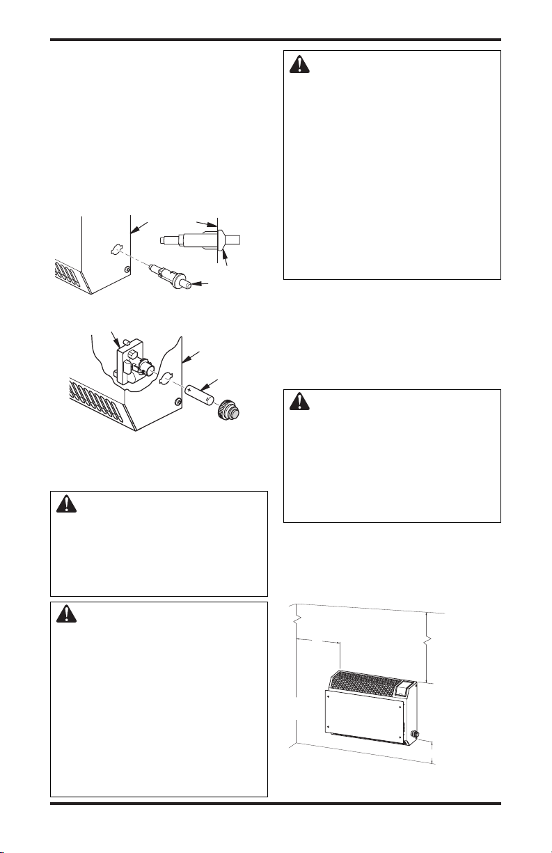
INSTALACIÓN
Como
mínimo a lo
s
lados del
calentador
Un mínimo
de 91.4 cm
(36")
5.1 cm (
2")
SUELO
TECHO
Lado
izquierdo
Lado
derecho
15.2 cm (6")
Distancia mínima
a la superficie
superior de la
alfombra, azulejo
u otro material
combustible
Side View
Continuación
4.
Para ambos encendedores, instale el cable del
encendedor sólo cuando se vuelva a colocar el panel
anterior del calentador después de conectarlo al
suministro de gas y de revisar las conexiones de gas
(consulte las páginas 11 a 13). Con la parte inferior del
panel anterior separada sólo de 5 a 7.6 cm (de 2" a 3")
del panel posterior, conecte el cable del encendedor a la
terminal del encendedor, en la esquina inferior derecha
del calentador (consulte la figura 4, en la página 8).
Figura 6 - Instalación del encendedor
Encendido electrónico
Figura 7 - Instalación del encendedor
UBICACIÓN DEL CALENTADOR
Este calentador está diseñado para montarse en una pared.
ADVERTENCIA: mantenga
las distancias mínimas que se
muestran en la figura 8. Si puede,
proporcione distancias mayores
respecto al suelo, al techo y a las
paredes adyacentes.
Lado derecho
del calentador
Encendedor
piezoeléctrico
piezoeléctrico
Lado derecho
del calentador
Batería
electrónico
PRECAUCIÓN: este calentador
crea corrientes de aire caliente.
Dichas corrientes mueven el calor
hacia la superficie de las paredes
próximas al calentador. La instala
ción del calentador cerca de recubri
-
mientos de vinilo o de tela en paredes
o la operación del calentador en
lugares donde existan impurezas en
el aire (como humo de tabaco, velas
aromáticas, líquidos limpiadores,
lámparas de aceite o keroseno, entre
otros), puede descolorar las paredes
o producir olores.
IMPORTANTE: los calentadores sin ventilación
añaden humedad al aire. Aunque esto es benéfico, la
instalación del calentador en habitaciones sin suficiente
aire de ventilación puede ocasionar la formación de
moho debido al exceso de humedad. Consulte Aire para
combustión y ventilación, en la página 5. Si hay mucha
humedad, se puede utilizar un deshumidificador para
ayudar a reducir el vapor de agua contenido en el aire.
PRECAUCIÓN: si instala el calen-
tador en la chochera de una casa :
•
el piloto y el quemador del calentador
deberán estar por lo menos a 45.7
cm (18") sobre el suelo
• sitúe el calentador donde algún
vehículo en movimiento no lo
pueda golpear
Para mayor comodidad y eficiencia, instale el calentador
• donde haya fácil acceso para la operación, inspección y reparación,
• en la parte más fría de la habitación.
Sitúe el calentador cerca de un enchufe eléctrico de
120 V 60 Hz (voltaje común en casas habitación).
ADVERTENCIA: nunca instale
el calentador
• en un dormitorio o baño
• en un vehículo recreativo
•
donde cortinas, muebles, ropa u otros
objetos inflamables estén a menos
de 92 cm (36") de las partes anterior,
superior o laterales del calentador
• como elemento de una chimenea
• en áreas de mucho tráfico
• en áreas con mucho viento o con
corrientes de aire fuertes
116292-01D 9
Figura 8 - Distancias mínimas de montaje
vistas desde la parte anterior del calentador
www.desatech.com

INSTALACIÓN
13" (33 cm)
Pa r ed a dya c ent e
Inserte los tornillos
de montaje sólo a
través del último orificio
de cada extremo
Suelo
Mínimo
30.4 cm
(12")
Mínimo
27.9 cm
(11")
Continuación
INSTALACIÓN DEL CALENTADOR
EN LA PARED
Soporte de montaje
Localice el soporte de montaje que se sujetó con cinta al
panel posterior del calentador para su transporte. Retire el
soporte de montaje del panel posterior del calentador.
Figura 9 - Soporte de montaje
Métodos para fijar el soporte de montaje
a la pared
Use únicamente el último orificio de cada extremo
del soporte de montaje para fijarlo a la pared. Entre
estos dos orificios hay 33 cm (13") de distancia. Fije el
soporte de montaje a la pared mediante una de las dos
maneras siguientes:
1. Instalación en viga de pared
2. Instalación en anclaje de pared
Instalación en viga de pared: con este método la
instalación queda más resistente. Inserte los tornillos de montaje en el soporte de montaje y en los
maderos de la pared.
Instalación en anclaje de pared: con este método
se puede montar el soporte en paredes huecas (área
entre las vigas) o en paredes sólidas (de concreto
o mampostería).
Decida cuál método se ajusta mejor a sus necesidades. Cualquiera de los dos métodos proporcionará
un apoyo seguro para el soporte de montaje.
Cómo marcar las ubicaciones de los tornillos
1. Fije el soporte de montaje a la pared con cinta,
en el lugar donde estará situado. Asegúrese de
que el soporte de montaje esté nivelado.
ADVERTENCIA: mantenga
las distancias mínimas que se
muestran en la figura 10. Si
puede, proporcione distancias
mínimas mayores con respecto
al suelo y la pared de unión.
2. Marque las ubicaciones de los tornillos en la
pared (consulte la figura 10).
Nota: marque únicamente el último orificio de
cada extremo del soporte de montaje. Inserte los
tornillos de montaje en estos orificios solamente.
3.
Quite la cinta y el soporte de montaje de la pared.
Instalación del soporte de montaje a la pared
Nota: los anclajes de pared, tornillos de montaje
y separadores están en el paquete de ferretería. El
paquete de ferretería se incluye con el calentador.
10
Figura 10 - Distancias mínimas del
Método de instalación en maderos de pared
Para fijar el soporte de montaje a las vigas de la pared
1. Perfore orificios en los lugares marcados utilizando una broca de 9/64".
2. Coloque el soporte de montaje en la pared. Alinee el último orificio de cada extremo del soporte
con los orificios que perforó en la pared.
3. Inserte los tornillos de montaje en el soporte y
en los maderos de la pared.
4. Apriete los tornillos hasta que el soporte de montaje esté asegurado firmemente a los maderos de
la pared.
Método de instalación en anclajes de pared
Para fijar el soporte de montaje en paredes huecas (el
área entre las vigas) o en paredes sólidas (de concreto
o mampostería)
1. Perfore orificios en los lugares marcados utilizando una broca de 5/16". Para las paredes
sólidas (de concreto o mampostería), perfore a
una profundidad de al menos 1".
2. Doble el anclaje de pared como se muestra en la
figura 11.
3. Inserte el anclaje de pared (las alas primero) en
el orificio. Golpee suavemente el anclaje para
introducirlo en la pared.
4. Para paredes delgadas, de 1.3 cm (1/2") o menos,
inserte la llave roja en el anclaje de pared. Empuje la llave roja para abrir las alas del anclaje.
IMPORTANTE: ¡no golpee la llave con un marti-
llo! para paredes gruesas, de más de 1.3 cm (1/2")
de ancho, o paredes sólidas, no abra las alas.
5. Coloque el soporte de montaje en la pared.
Alinee el último orificio de cada extremo del
soporte con los anclajes de pared.
6. Inserte los tornillos de montaje en el soporte y
en los anclajes de pared.
7. Apriete los tornillos hasta que el soporte de
montaje esté asegurado firmemente a la pared.
Figura 11 - Cómo
doblar el anclaje
www.desatech.com
soporte de montaje
Figura 12 - Cómo abrir
las alas del anclaje para
paredes delgadas
116292-01D

Vista lateral
Vi
sta frontal
INSTALACIÓN
Continuación
Colocación del calentador en el soporte de
montaje
1. Localice las dos ranuras horizontales en el panel
posterior del calentador.
2. Coloque el calentador en el soporte de montaje.
Deslice las ranuras horizontales hacia las lengüetas salientes del soporte de montaje.
Ranuras horizontales
Calentador
Pared
Separador
Figura 14 - Instalación de los tornillos de
montaje inferiores
CONEXIÓN AL SUMINISTRO DE GAS
Soporte de montaje
Lengüeta saliente
Figura 13 - Montaje del calentador en el
Instalación de los tornillos de montaje
inferiores
1. Localice los dos orificios de montaje inferiores.
2. Marque la ubicación de los tornillos en la pared.
3. Quite el calentador del soporte de montaje.
4. Si va a instalar los tornillos de montaje inferiores
Si va a instalar el tornillo inferior de montaje en
5. Vuelva a colocar el calentador en el soporte de
6. Coloque los separadores entre los orificios de
7. Sostenga el separador en su sitio con una mano.
8. Apriete los tornillos hasta que el calentador esté
Nota: no coloque el panel anterior en este mo-
116292-01D 11
soporte de montaje
Estos orificios se encuentran cerca de la parte
inferior del panel posterior del calentador (con
sulte la figura 14).
en una pared hueca o sólida, instale los anclajes
de pared. Siga los pasos 1 al 4 del Método de
instalación en anclajes de pared, en la página 10.
el madero de la pared, perfore orificios con una
broca de 9/16" en las ubicaciones marcadas.
montaje.
montaje inferiores y el anclaje de pared o el
orificio que perforó.
Con la otra mano, inserte el tornillo de montaje
en el orificio inferior de montaje y el separador.
Coloque la punta del tornillo en la abertura del
anclaje de pared o del orificio que perforó.
asegurado firmemente a la pared. No los apriete
demasiado.
mento. Ponga el panel anterior en su lugar hasta
después de haber hecho las conexiones de gas y
haber revisado que no haya fuga.
(fijado a la pared)
www.desatech.com
ADVERTENCIA: este aparato
requiere una conexión de entrada
tipo NPT (Rosca de tubería nacional)
de 3/8" al regulador de presión.
ADVERTENCIA: una persona de
-
servicio capacitada debe conectar
el calentador al suministro de gas.
Siga todos los códigos locales.
ADVERTENCIA: para gas natural,
nunca conecte el calentador a pozos
de gas privados (que no sean de
servicio público). Este gas se conoce
comúnmente como gas de pozo.
IMPORTANTE: para gas natural, verifique la presión
de la línea de gas antes de conectar el calentador a
la misma. La presión de la línea de gas no debe ser
de más de 10.5" de agua. Si la presión de la línea de
gas es mayor, se pueden producir daños al regulador
del calentador.
PRECAUCIÓN: para propano o
gas LP, nunca conecte el calentador directamente al suministro de
propano o gas LP. Este calentador
requiere un regulador externo (no
se incluye). Instale el regulador
externo entre el calentador y el
suministro de propano o gas LP.

INSTALACIÓN
Continuación
Para propano o gas LP, el instalador debe proveer un regulador externo. El regulador externo reducirá la presión
del gas entrante. Usted debe reducir la presión del gas
entrante de manera que esté entre 11" y 14" de agua. Si
no reduce la presión del gas entrante, se pueden producir
daños al regulador del calentador. Instale el regulador
externo con la ventosa apuntando hacia abajo, como se
muestra en la figura 15. Si apunta la ventila hacia abajo
se protege de la lluvia helada o aguanieve.
PRECAUCIÓN: utilice únicamente tubería nueva de hierro negro o
de acero. En ciertas áreas, se puede
usar tubería de cobre galvanizada
internamente. Consulte los códigos
locales. utilice tubería de un diámetro
lo suficientemente grande para que
permita el paso del volumen de gas
adecuado al calentador. Si la tubería
es demasiado angosta, se producirá
una pérdida indebida de volumen.
Diámetro común de las tuberías de entrada: 9.5 mm (3/8") o más
La instalación debe incluir la válvula de cierre del
equipo, la unión y el tapón con rosca de 1/8" tipo
NPT. Sitúe la conexión NPT a su alcance para la conexión del medidor de prueba. La conexión NPT debe
estar antes del calentador (consulte la figura 16).
IMPORTANTE: instale una válvula de cierre del equipo
en un lugar que sea accesible. La válvula de cierre del equi
po es para abrir o cerrar el suministro de gas al aparato.
Aplique una pequeña cantidad de sellador de tubería a las
roscas NPT macho. Esto evitará que el exceso de sellador
entre a la tubería. El exceso de sellador en la tubería puede
ocasionar que las válvulas del calentador se tapen.
ADVERTENCIA: use sellador
para tubería que sea resistente al
gas de petróleo líquido (LP).
Tanque de
suministro
de propano
o gas LP
Figura 15 - Regulador externo con la
ventila apuntando hacia abajo
12
Regulador
externo
Ventila
apuntando
hacia abajo
www.desatech.com
Instale la trampa de sedimentos en la línea de suministro como se muestra en la figura 16. Sitúe la trampa
de sedimentos de manera que esté accesible para
limpieza. Sitúe la trampa de sedimentos donde sea
poco probable que los materiales atrapados en ella se
congelen. La trampa de sedimentos atrapa humedad
y contaminantes. Esto evita que éstos lleguen a los
controles del calentador. Si la trampa de sedimentos
no se instala o se instala incorrectamente, es posible
que el calentador no funcione correctamente.
IMPORTANTE: sujete el regulador de presión con
una llave cuando lo conecte a la tubería de gas o a
otros conectores. No apriete demasiado la conexión
de la tubería al regulador. El cuerpo del regulador
se podría dañar.
Regulador
de presión
Niple para
tubería con
rosca de 3/8"
tipo NPT
Unión T
Buje reduc
tor a 1/8"
tipo NPT
Tapón
con rosca
de 1/8 de
pulgada
tipo NPT
Unión Niple Tapón
Conexión del medidor de prueba*
T de tubo
-
Trampa de sedimentos
* Una válvula de cierre de equipo con diseño certificado por la CSA con rosca tipo NPT de 1/8" es
una alternativa aceptable a la conexión de medidor
de prueba. Adquiera la válvula opcional de cierre
de equipo certificada con diseño CSA del distribuidor. Consulte Accesorios, en la página 23.
-
Figura 16 - Conexión de gas
Gabinete del
calentador
Válvula de
cierre del
equipo *
Gas natural
Mín.
7.6 cm
medidor de
(3")
gas (presión
de 4" a 10.5" de c.a.)
Propano o gas LP
Del regulador externo (presión de 11" a
14" de c.a.)
REVISIÓN DE LAS CONEXIONES DE
GAS
ADVERTENCIA: pruebe todas las conexiones y tubería de
gas, tanto internas como externas, para verificar que no haya
fugas después de la instalación
o reparación. Repare todas las
fugas inmediatamente.
116292-01D
Desde el

INSTALACIÓN
Continuación
ADVERTENCIA: nunca use una
llama al descubierto para buscar
fugas. Aplique algún líquido no
corrosivo para detectar fugas en
todas las uniones. La formación de
burbujas indicará una fuga. Repare
todas las fugas inmediatamente.
PRECAUCIÓN: para propano
o gas LP, asegúrese de que el re
gulador externo se haya instalado
entre el suministro de propano o
gas LP y el calentador. Consulte
las directrices en Conexión al su
ministro de gas en la página 11.
PRUEBAS DE PRESIÓN EN EL SISTEMA
DE TUBERÍA DEL SUMINISTRO DE GAS
Pruebas de presión mayores a 1/2 PSI (3.5 kPa)
1.
Desconecte el aparato del sistema de tubería de
suministro de gas por medio de la válvula principal
de gas del aparato (válvula de control) y de la válvula
de cierre del equipo. Las presiones que excedan 1/2
PSI ocasionarán daños al regulador del calentador.
2. Coloque una tapa en el extremo abierto del tubo
de gas donde estaba conectada la válvula de
cierre del equipo.
3. Regule la presión del sistema de tubería de
suministro ya sea abriendo la válvula del tanque
de suministro de propano o gas LP, en caso
que utilice este tipo de gas, o bien, abriendo la
válvula principal de gas que se localiza en el
medidor de gas natural o cerca de éste, o bien,
usando aire comprimido.
4.
Revise todas las uniones del sistema de tubería de suministro de gas. Aplique en todas las uniones algún
fluido de detección de fugas que no sea corrosivo.
La formación de burbujas indicará una fuga.
5. Repare todas las fugas inmediatamente.
6.
Vuelva a conectar el calentador y la válvula de cierre
del equipo al suministro de gas. Revise los conectores
que se volvieron a colocar en busca de fugas.
Pruebas de las presiones iguales o
menores a 1/2 PSI (3.5 kPa)
1. Cierre la válvula de cierre del equipo (consulte
la figura 17).
2.
Regule la presión del sistema de tubería de suministro ya sea abriendo la válvula del tanque de
suministro de propano o gas LP, en caso que utilice
este tipo de gas, o bien, abriendo la válvula principal
de gas que se localiza en el medidor de gas natural
o cerca de éste, o bien, usando aire comprimido.
3.
Revise todas las uniones entre el medidor de gas,
116292-01D 13
-
-
www.desatech.com
si usa gas natural (consulte la figura 18), o entre el
tanque de suministro de propano o gas LP, si usa este
tipo de gas, y la válvula de cierre del equipo (consulte la figura 19). Aplique en todas las uniones algún
fluido de detección de fugas que no sea corrosivo.
La formación de burbujas indicará una fuga.
4. Repare todas las fugas inmediatamente.
COMPROBACIÓN DE LA PRESIÓN DE LAS
CONEXIONES DE GAS DEL CALENTADOR
1. Abra la válvula de cierre del equipo (consulte la
figura 17).
2. Si usa gas natural, abra la válvula principal de
gas ubicada en el medidor de gas o cerca de
éste. Si usa propano o gas LP, abra la válvula
de suministro de propano o gas LP.
3. Compruebe que la perilla de control del calentador esté en la posición OFF (apagado).
Revise todas las uniones entre la válvula de cierre del
4.
equipo y válvula de gas del termostato (consulte la
figura 18 ó 19). Aplique en todas las uniones algún
fluido de detección de fugas que no sea corrosivo.
La formación de burbujas indicará una fuga.
5. Repare todas las fugas inmediatamente.
6. Encienda el calentador (consulte Funcionamiento
del calentador, en la página 14). Revise todas las
demás uniones internas para ver si hay fugas.
7. Apague el calentador (consulte Cómo cerrar el
suministro de gas al calentador, en la página 15).
8. Conecte el cable del encendedor y vuelva a
colocar el panel anterior.
Válvula de
cierre de
equipo
Figura 17 - Válvula de cierre del equipo
Medidor
de gas
Figura 18 - Revisión de las uniones de
Tanque de
suministro
de propano
o gas LP
Figura 19 - Revisión de las uniones de
gas para gas natural
gas para propano o gas LP
Abierta
Cerrada
Válvula de
cierre de equipo
Válvula de
cierre de equipo

INSTALACIÓN
Continuación
CONEXIÓN A LA ALIMENTACIÓN
ELÉCTRICA
ADVERTENCIA: el ventilador
debe estar conectado a tierra. El
ventilador tiene una clavija de tres
patas con conexión a tierra como se
muestra en la figura 20. La clavija es la
protección contra electrocución. Conéctela en un enchufe de tres orificios
con conexión a tierra. En caso que
el cable deba reemplazarse, utilice
únicamente un cable con clavija de
tres patas con conexión a tierra.
PRECAUCIÓN: marque todos
los cables antes de desconec
tarlos. Los errores de cableado
pueden ocasionar que el funcionamiento sea incorrecto y peligroso
(consulte la página 22).
Enchufe
conectado
a tierra
Clavija con
conexión a tierra
Figura 20 - Clavija con conexión a tierra
CABLE DE EXTENSIÓN
Utilice un cable de extensión en caso que lo necesite. El
cable debe tener una clavija de tres patas con conexión
a tierra un enchufe de tres orificios. Compruebe que el
cable esté en buen estado. Debe ser suficientemente
grueso para soportar la corriente necesaria. Si el cable
es más delgado se producirá una caída en la línea de
voltaje. Esto ocasionará pérdida de potencia y sobre
calentamiento. Para longitudes inferiores a 15.24 m
(50 pies) utilice un cable AWG No. 16.
PRECAUCIÓN: después de realizar el servicio compruebe que el calentador funcione correctamente.
-
Funcionamiento del ventilador
El ventilador está conectado a un termostato. El
ventilador empieza a funcionar cuando la unidad se
calienta. El ventilador deja de funcionar pocos minutos
después de que la unidad está en el ciclo apagado o es
desconectada. Así, el ventilador se encenderá y apagará
de manera cíclica. Nota
mostato, el calentador y el termostato no se encenderán
y apagarán exactamente al mismo tiempo. La duración
de los ciclos del ventilador depende de la temperatura
que se establezca en el calentador.
: si tiene un calentador con ter-
FUNCIONAMIENTO DEL
CALENTADOR
PARA SU SEGURIDAD, LEA ESTO
ANTES DE ENCENDERLO
ADVERTENCIA: no seguir
estas instrucciones al pie de la
letra puede resultar en incendio
o explosión que produzcan daños a bienes, lesiones físicas o
la muerte.
A. Este aparato tiene un piloto que se debe encen-
der manualmente. Cuando encienda el piloto,
siga estas instrucciones al pie de la letra.
B. ANTES DE ENCENDERLO compruebe
que alrededor del aparato no huela a gas.
Asegúrese de oler también cerca del suelo ya
que algunos gases son más pesados que el aire
y se asientan cerca del suelo.
QUÉ HACER SI PERCIBE OLOR A GAS
• No intente encender ningún aparato.
• No toque ningún interruptor eléctrico; no
use ningún teléfono en el edificio.
• Llame inmediatamente a su proveedor de
gas desde el teléfono de algún vecino. Siga
las instrucciones del proveedor de gas.
• Si no puede localizar al proveedor de gas,
llame al departamento de bomberos.
C. Utilice únicamente la mano para presionar o
girar la perilla de control de gas. Nunca utilice
herramientas. Si no puede presionar o girar
la perilla manualmente, no intente repararla,
llame a un técnico de servicio capacitado
Forzar o tratar de repararla puede producir
un incendio o una explosión.
-
D. No use este aparato si alguna de sus partes estu
vo sumergida en agua. Llame inmediatamente
a un técnico de servicio capacitado para que
inspeccione el aparato y reemplace las piezas
del sistema de control y los controles de gas
que hayan estado sumergidos en agua.
-
14
www.desatech.com
116292-01D

O
F
F
P
I
L
O
T
FUNCIONAMIENTO DEL
OFF
O
F
F
P
I
L
O
T
CALENTADOR Continuación
INSTRUCCIONES
9. Gire la perilla de control en sentido contrario
al de las manecillas del reloj hasta la
temperatura deseada. El quemador principal
deberá encenderse.
DE ENCENDIDO
1. ¡ALTO! Lea la información de seguridad, en
la página 14.
2. Asegúrese de que la válvula de cierre del equipo
esté completamente abierta.
3. Si va a realizar algún trabajo de mantenimiento, desconecte el suministro de energía eléctrica
al calentador.
4. Gire la perilla de control en dirección de la
manecillas del reloj hasta la posición
(OFF) apagado.
5. Espere cinco minutos a que se disipe el gas.
Luego, compruebe que no huela a gas, incluso
cerca del suelo. Si percibe olor a gas, DETÉNGASE. Siga el punto “B” de la información de
seguridad, en la página 14.. Si no percibe olor
a gas, continúe con el siguiente paso.
6. Gire la perilla de control en sentido contrario
al de las manecillas del reloj hasta la posición PILOT (piloto). Mantenga presionada la
perilla de control durante cinco (5) segundos.
7. Con la perilla de control presionada, oprima y
suelte el botón del encendido. Esto encenderá
el piloto. El piloto está instalado en la parte
anterior del quemador. Nota: posiblemente
ésta sea la primera vez que hace funcionar el
calentador después de conectarlo al suministro
de gas. Si es así, es posible que deba presionar
la perilla de control durante 30 segundos o más.
Esto permitirá que el aire salga del sistema de
gas. Si es necesario, continúe presionando el
botón del encendedor hasta que el piloto se
encienda. En caso que el piloto no encienda,
consulte la sección Solución de problemas, en
la página 18 o llame a un técnico de servicio
calificado o a su proveedor de gas para que
realicen las reparaciones necesarias. Encienda
el piloto con un fósforo hasta que se realicen las
reparaciones. Para encender el piloto con un
fósforo, consulte el Procedimiento de encendido
manual, en la página 16.
8. Una vez que haya encendido el piloto mantenga
la perilla de control presionada durante 30
segundos. Después de los 30 segundos, suelte
la perilla de control.
• Si la perilla de control no regresa a su posición original después de soltarla, comuníquese con una persona de servicio calificada
o con el proveedor de gas para que se hagan
las reparaciones.
Nota: si el piloto se apaga, repita los pasos 4 al 7.
Los modelos con termostato cuentan con sistema
de bloqueo de seguridad. Espere un (1) minuto
antes de encender el piloto nuevamente.
116292-01D 15
www.desatech.com
ADVERTENCIA: siempre haga
funcionar los calentadores con
control manual en las posiciones
de bloqueo. El funcionamiento entre
estas posiciones puede generar un
riesgo para la salud si se usa en una
habitación con poca ventilación. Lea
el manual del propietario para obte
ner las instrucciones completas.
PRECAUCIÓN: no trate de ajustar la temperatura por medio de la
válvula de cierre del equipo.
Figura 21 - Perilla de control en la
Encendido
piezoeléctrico
Figura 23 - Piloto (el piloto real puede
Cómo apagar el calentador
1. Gire la perilla de control en dirección de la
manecillas del reloj hasta la posición
(OFF) apagado.
2. Si va a realizar algún trabajo de mantenimiento, desconecte el suministro de energía eléctrica
al calentador.
Cómo apagar sólo el quemador (sin que se
apague el piloto)
Gire la perilla de control en el sentido de las
manecillas del reloj hasta la posición
PILOT (piloto).
posición de apagado
Encendido
electrónico
Figura 22 - Botones de encendido
Termopar
Electrodo del encendido
Quemador
del piloto
ser distinto)
CÓMO CERRAR EL SUMINISTRO
DE GAS AL CALENTADOR
-

FUNCIONAMIENTO DEL
CALENTADOR Continuación
FUNCIONAMIENTO DEL
CONTROL DEL TERMOSTATO
El control termostático que se usa en estos modelos
es distinto de los termostatos convencionales. Los
termostatos convencionales simplemente encienden
y apagan el quemador. El termostato que se usa en
este calentador detecta la temperatura de la habitación. El termostato ajusta la cantidad del flujo de gas
que llega al quemador. Esto aumenta o disminuye la
altura de la llama del quemador. Algunas veces, la
temperatura de la habitación puede ser mayor que la
establecida. Si esto ocurre, el quemador se apagará.
El quemador volverá a encenderse cuando la temperatura de la habitación disminuya por debajo de la
temperatura que se estableció. La perilla de control
se puede colocar en cualquier nivel de calor entre 1 y
5. En la mayoría de los casos, la selección del nivel 5
hará que el quemador permanezca completamente
encendido sin modulación.
Nota: el bulbo sensor de termostato mide la temperatura del aire cercano al gabinete del calentador. Es posible que ésta no siempre concuerde con la temperatura
de la habitación (dependiendo de la construcción de la
habitación, la ubicación de la instalación, el tamaño de
la habitación, las temperaturas en exteriores, etc.). El
uso frecuente del calentador le permitirá determinar
los niveles que le resultan más cómodos.
PROCEDIMIENTO DE
ENCENDIDO MANUAL
1. Desmonte el panel anterior (consulte la figura
4, página 8).
2. Realice los pasos 1 al 7 de las Instrucciones de
encendido, página 15.
3. Con la perilla de control presionada, encienda
un fósforo. Sostenga el fósforo en el piloto
hasta que este último se encienda.
4. Una vez que haya encendido el piloto mantenga
la perilla de control presionada durante 30
segundos. Después de los 30 segundos, suelte la
perilla de control. Continúe en el paso 9 de las
Instrucciones de encendido, en la página 15.
5. Vuelva a colocar el panel anterior.
INSPECCIÓN DEL
CALENTADOR
Revise frecuentemente los patrones de la llama del
piloto y de la llama del quemador.
PATRÓN DE LA LLAMA DEL PILOTO
La figura 24 muestra un patrón correcto de la llama del
piloto. La figura 25 muestra un patrón incorrecto de la
llama del piloto. La llama incorrecta del piloto no toca
el termopar. Esto hará que el termopar se enfríe. Cuando
el termopar se enfríe, el calentador se apagará.
Si el patrón de la llama del piloto es incorrecto, como
se muestra en la figura 25
16
www.desatech.com
• apague el calentador (consulte Cómo el suministro
de gas al calentador, en la página 15)
• consulte Solución de problemas
Nota: la llama del piloto en las unidades de gas natural presentará una ligera curva, pero la llama deberá
ser azul, sin color amarillo ni naranja.
Termopar
Figura 24 - Patrón
correcto de la llama
Llama azul
Termopar
Quemador
del piloto
del piloto
, página 18
Llama amarilla
Figura 25 - Patrón
incorrecto de la
llama del piloto
PATRÓN DE LA LLAMA DEL
CALENTADOR
ADVERTENCIA: si se presenta
un color amarillo en las puntas de
las llamas, el calentador puede
producir niveles elevados de
monóxido de carbono.
AVISO: no confunda las llamas anaranjadas con el color amarillo en las
puntas. El polvo y otras partículas
pequeñas se introducen al calenta
dor y al quemarse producen breves
manchas de llamas anaranjadas.
La figura 26 muestra un patrón correcto de la llama
del quemador. La figura 27 muestra un patrón inco
rrecto de la llama del quemador. El patrón incorrecto
de la llama del quemador produce las puntas amari
llas de las llamas. También muestra llamas más altas
que la mitad de la altura del panel de vidrio.
Si el patrón de la llama del quemador es incorrecto,
como se muestra en la figura 27:
• apague el calentador (consulte
de gas al calentador
• consulte Solución de problemas, en la página 18
Figura 26 - Patrón correcto de la llama
Figura 27 - Patrón incorrecto de la llama
, en la página 15)
del quemador
del quemador
Cómo el suministro
Llama azul
1
/2 de la
altura del
deflector
Puntas
amarillas
1
2
/
de la
altura del
deflector
116292-01D
-
-

LIMPIEZA Y
MANTENIMIENTO
ADVERTENCIA: apague el
calentador y deje que se enfríe
antes de limpiarlo.
PRECAUCIÓN: debe mantener
limpias las áreas de control, el que
mador y los pasajes de circulación
de aire del calentador. Inspeccione
estas áreas del calentador antes de
cada uso. Haga que una persona
de servicio calificada inspeccione
el calentador una vez al año. Es
posible que el calentador requiera
limpieza más frecuente debido a
exceso de pelusa proveniente de
alfombras, de camas, de pelo de
mascotas, etc.
ADVERTENCIA: si no mantiene
limpias las aberturas principales
del quemador se puede producir
hollín y daños a la propiedad.
-
no sea mayor de 30 PSI. Es posible que la tienda
local de equipo de cómputo, ferretería o de mejoras
al hogar tengan aire comprimido en latas. Puede
usar una aspiradora en la función de expulsión de
aire. Si utiliza aire comprimido en lata, siga las
instrucciones que aparecen en la lata. Si no sigue
las instrucciones escritas en la lata, puede dañar el
ensamblaje del piloto.
1. Apague la unidad, incluso el piloto. Deje que
la unidad se enfríe durante al menos treinta
minutos.
2. Inspeccione el piloto del quemador en busca de
polvo y tierra.
3. Haga pasar aire a través de los puertos o ranuras
y los orificios del quemador.
4. Nunca inserte objetos en el tubo del piloto.
Limpie también el ensamblaje del piloto. Una punta
amarilla en la llama del piloto indica la presencia de
polvo y tierra en el ensamblaje del mismo. Hay una
pequeña entrada de aire del piloto a aproximadamente
cinco centímetros (dos pulgadas) de donde sale la
llama del piloto del ensamblaje del mismo (consulte
la figura 28). Con la unidad apagada, introduzca
aire suavemente a través de la entrada de aire. Si no
cuenta con aire comprimido, puede soplar a través
de una pajilla o popote.
Ensamblaje
del piloto
PILOTO CON ODS Y QUEMADOR
Utilice una aspiradora, aire a presión o un cepillo de
cerdas suaves para la limpieza.
ENTRADA DE AIRE AL PILOTO DEL
QUEMADOR
Los orificios de la entrada de aire principal permiten
que la cantidad correcta de aire se mezcle con el gas.
Esto produce una llama de combustión limpia. Mantenga estos orificios libres de tierra, polvo y pelusa.
Limpie estos orificios de entrada de aire antes de cada
temporada de calefacción. Si los orificios de aire están bloqueados, producirán hollín. Se recomienda que
limpie la unidad cada tres meses de funcionamiento
y que solicite que una persona de servicio capacitada
inspeccione el calentador cada año.
También se recomienda que mantenga el ensamblaje
de tubo y piloto del calentador limpios y libres de
polvo y tierra. Para limpiar estas piezas, se reco
mienda que use aire comprimido a una presión que
116292-01D 17
-
www.desatech.com
Entrada de
aire al piloto
Figura 28 - Entrada de aire del piloto; se
muestra el piloto para propano o gas LP
(el piloto real puede ser distinto que el
que aparece en la ilustración)
GABINETE
Conductos de aire
Use una aspiradora o aire a presión para la limpieza.
Exterior y vidrio anterior de acrílico oscuro
Utilice un paño humedecido con una mezcla de agua y
jabón suave. Frote el gabinete para quitar el polvo.

SOLUCIÓN DE PROBLEMAS
ADVERTENCIA: apague y desconecte el calentador y deje que
se enfríe antes de darle servicio. Sólo una persona de servicio capacitada debe reparar el calentador o darle servicio.
PRECAUCIÓN: nunca utilice un alambre, aguja u objetos parecidos para limpiar el piloto/ODS. Esto puede dañar la unidad de
piloto con ODS.
Nota: todos los puntos para solución de problemas se listan en orden de funcionamiento.
PROBLEMA OBSERVADO
Cuando se presiona el botón del
encendido, no hay chispa en el
piloto con ODS
CAUSA POSIBLE
1. El electrodo del encendido está
colocado incorrectamente
2. El electrodo del encendido
está averiado
3. El electrodo del encendido
no está conectado al cable del
encendido
4. El cable del encendido está
pellizcado o mojado
5. El cable del encendido está
roto
6. El encendido piezoeléctrico
está defectuoso
REMEDIO
1. Reemplace el ensamblaje del
piloto
2. Reemplace el ensamblaje del
piloto
3. Vuelva a conectar el cable del
encendido
4. Libere el cable del encendido
si algún metal o tubería lo está
pellizcando. Mantenga seco el
cable del encendido
5. Reemplace el cable del encendido
6. Reemplace el encendido pie
zoeléctrico
-
Cuando se presiona el botón del
encendido, hay chispa en el piloto
con ODS pero no se enciende
18
1. El suministro de gas está
cerrado o la válvula de cierre
del equipo está cerrada
2. La perilla de control no está
en la posición de piloto
3. La perilla de control no está
presionada mientras está en
la posición de piloto
4. Presencia de aire en las líneas
de gas cuando se instalaron
5. Se agotó el suministro de gas
(sólo para propano o gas LP)
6. El piloto con ODS está tapado
7. La posición del regulador de
gas no es la correcta
www.desatech.com
1. Abra el suministro de gas o la
válvula de cierre del equipo
2. Gire la perilla de control a la
posición de piloto
3. Presione la perilla de control
mientras esté en la posición de
piloto
4. Mantenga la perilla de control
presionada. Repita la operación de encendido hasta que
se expulse el aire
5. Comuníquese con la compañía
local de propano o gas LP
6. Limpie el piloto con ODS
(consulte Limpieza y mante
nimiento, en la página 17) o
reemplace el ensamblaje del
piloto con ODS
7. Reemplace el regulador de
gas
116292-01D
-

SOLUCIÓN DE PROBLEMAS
PROBLEMA OBSERVADO
El piloto con ODS se enciende
pero la llama se extingue cuando
se suelta la perilla de control
Continuación
CAUSA POSIBLE
1. La perilla de control no está
presionada completamente
2. La perilla de control no se
presionó durante el tiempo
suficiente
3. El sistema de interbloqueo de
seguridad se ha activado
4. La válvula de cierre del equipo
no está totalmente abierta
5. La conexión del termopar está
floja en la válvula de control
6. La llama del piloto no está
tocando el termopar, lo que
hace que el termopar se enfríe
y ocasiona que la llama del
piloto se extinga. Este problema puede ser ocasionado
por alguna de las siguientes
condiciones o por ambas:
A) baja presión del gas
B) el piloto con ODS está
sucio o parcialmente tapado
7. El termopar está dañado
8.
La válvula de control está dañada
REMEDIO
1. Presione totalmente la perilla
de control
2. Después de que el piloto con
ODS se encienda, mantenga la
perilla de control presionada
durante 30 segundos
3. Espere un minuto a que el
sistema de interbloqueo de seguridad se restablezca. Repita
la operación de encendido
4. Abra la válvula de cierre del
equipo totalmente
5. Apriete con la mano hasta que
sienta que tope, luego apriete
1/4 de vuelta más
6. A) Comuníquese con la com
pañía local de gas natural o de
propano o gas LP
B) Limpie el piloto y el ODS
(consulte Limpieza y mante
nimiento, en la página 17) o
reemplace el ensamblaje del
piloto con ODS
7. Reemplace el ensamblaje del
piloto
8.
Reemplace la válvula de control
-
-
El quemador no se enciende
después de que el piloto con ODS
está encendido
Encendido demo r a d o del
quemador
El quemador muestra llamas de
retorno durante la combustión
116292-01D 19
1. El orificio del quemador está
tapado
2. La presión del gas de entrada
es demasiado baja
1. La presión del tubo múltiple
es demasiado baja
2. El orificio del quemador está
tapado
1. El orificio del quemador está
tapado o dañado
2. El quemador está dañado
3. El regulador de gas está defec
tuoso
www.desatech.com
1. Limpie el quemador (consulte
Limpieza y mantenimiento, en
la página 17) o reemplace el
orificio del quemador
2. Comuníquese con la compa
ñía local de gas natural o de
propano o gas LP
1. Comuníquese con la compa
ñía local de gas natural o de
propano o gas LP
2. Limpie el quemador (consulte
Limpieza y mantenimiento, en
la página 17) o reemplace el
orificio del quemador
1. Limpie el quemador (consulte
Limpieza y mantenimiento, en
la página 17) o reemplace el
orificio del quemador
2. Reemplace el quemador
-
3. Reemplace el regulador de
gas
-
-

SOLUCIÓN DE PROBLEMAS
PROBLEMA OBSERVADO
Llamas amarillas durante la
combustión en el quemador
Continuación
CAUSA POSIBLE
1. No hay suficiente aire
2. El regulador de gas está defectuoso
3. El quemador está obstruido o
sucio
REMEDIO
1. Revise el quemador en busca
de polvo y residuos. Si los hay,
limpie el quemador (consulte
Limpieza y mantenimiento, en
la página 17)
2. Reemplace el regulador de
gas
3. Limpie el quemador (consulte
Limpieza y mantenimiento, en
la página 17)
Un poco de humo u olor durante
el funcionamiento inicial
El calentador produce un ruido
silbante cuando el quemador está
encendido
Se forma un residuo de polvo
blanco dentro de la caja del
quemador o en las paredes o
muebles contiguos
El ventilador no se enciende
1. Hay residuos provenientes de
procesos de fabricación
1. La perilla de control se giró
a la posición 5 cuando el
quemador estaba frío
2. Hay aire en la línea de gas
3. Los conductos de aire en el
calentador están bloqueados
4. El orificio del quemador está
sucio o parcialmente obstruido
1. Cuando se calientan, los va
pores provenientes de los
pulidores de muebles, cera,
limpiadores de alfombras,
etc., pueden convertirse en
residuos de polvo blanco
1. El cable de alimentación no
está conectado
2. El enchufe no tiene corriente
3. Demora en espera de que se
caliente el interruptor térmico
4. Interruptor en mal estado
5. Cable suelto
1. El problema desaparecerá
después de algunas horas de
funcionamiento
1. Gire la perilla de control a
la posición 1 y deje que se
caliente durante un minuto
2. Haga funcionar el quemador
hasta que se elimine el aire
de la línea. Solicite a la com
pañía local de gas natural o de
propano o gas LP que revise la
línea de gas
3. Respete las distancias míni
mas de instalación (consulte
la figura 8, en la página 9)
4. Limpie el quemador (consulte
Limpieza y mantenimiento, en
la página 17) o reemplace el
orificio del quemador
-
1. Apague el calentador cuando
utilice pulidores de muebles,
ceras, limpiadores de alfom
bras o productos parecidos.
1. Conecte el cable de alimenta
ción en un enchufe de 120 V
60 Hz
2.
Pida a una persona de servicio calificada que revise si hay voltaje
en el enchufe
3. Espere de 4 a 5 minutos con
el quemador encendido
4. Reemplace el interruptor
5. Conecte los cables
-
-
-
-
El calentador produce un ruido de
chasquidos o golpeteos metálicos
justo después de que el quemador
se enciende o se apaga
20
1. Los metales se dilatan al
calentarse y se contraen al
enfriarse
www.desatech.com
1. Esto es común en la mayoría de
los calentadores. Si el ruido es
excesivo, comuníquese con una
persona de servicio capacitada
116292-01D

SOLUCIÓN DE PROBLEMAS
Continuación
ADVERTENCIA: si percibe olor a gas
• Cierre el suministro de gas
• No intente encender ningún aparato
• No toque ningún interruptor eléctrico; no use ningún teléfono en
el edificio
• Llame inmediatamente a su proveedor de gas desde el teléfono
de algún vecino. Siga las instrucciones del proveedor de gas
• Si no puede localizar al proveedor de gas, llame al departamento
de bomberos
IMPORTANTE: si hace funcionar el calentador donde existen impurezas en el aire se pueden producir
olores. Los productos de limpieza, pintura, solventes de pintura, humo de cigarro, cementos y pegamentos,
alfombras o textiles nuevos, etc., producen gases. Estos gases se pueden mezclar con el aire que se utiliza
para la combustión y producir olores.
PROBLEMA OBSERVADO
El calentador produce olores no
deseados
CAUSA POSIBLE
1.
El calentador está quemando
vapores provenientes de pintura,
aerosoles para cabello, pegamen
tos, etc. (consulte la declaración
IMPORTANTE anterior)
2.
Hay poco suministro de combustible (sólo para propano o gas LP)
3. Fugas de gas. Consulte la
declaración de adverten
cia anterior
REMEDIO
1. Ventile la habitación. Deje
de usar los productos que
ocasionan el olor mientras el
calentador esté funcionando
2. Llene el tanque de suministro
3. Localice y repare todas las
fugas (consulte Revisión de
-
las conexiones de gas, en la
página 12)
El calentador se apaga mien
tras se está usando (el ODS
funciona)
Hay olor a gas incluso cuando
la perilla de control está en la
posición OFF (apagado)
Hay olor a gas durante la combustión
Hay humedad o condensación
en las ventanas
116292-01D 21
1. No hay suficiente aire fresco
-
2. Hay poca presión en la línea
3. El piloto con ODS está parcialmente tapado
1. Fugas de gas. Consulte la
declaración de adverten
cia anterio
2. La válvula de control está
defectuosa
1.
Hay materiales extraños entre la
válvula de control y el quemador
2. Fugas de gas. Consulte la
declaración de adverten
cia anterio
1. No hay suficiente aire para
combustión o ventilación
www.desatech.com
1. Abra la ventana y/o la puerta
para dar ventilación
2. Comuníquese con la compa
ñía local de gas natural o de
propano o gas LP
3. Limpie el piloto con ODS
(consulte Limpieza y mante
nimiento, en la página 17)
1. Localice y repare todas las
fugas (consulte Revisión de
-
las conexiones de gas, en la
página 12)
2. Reemplace la válvula de con
trol
1.
Desensamble la tubería de gas y
extraiga los materiales extraños
2. Localice y repare todas las
fugas (consulte Revisión de
-
las conexiones de gas, en la
página 12)
1. Consulte los requisitos de Aire
para combustión y ventila
ción, (página 5)
-
-
-
-
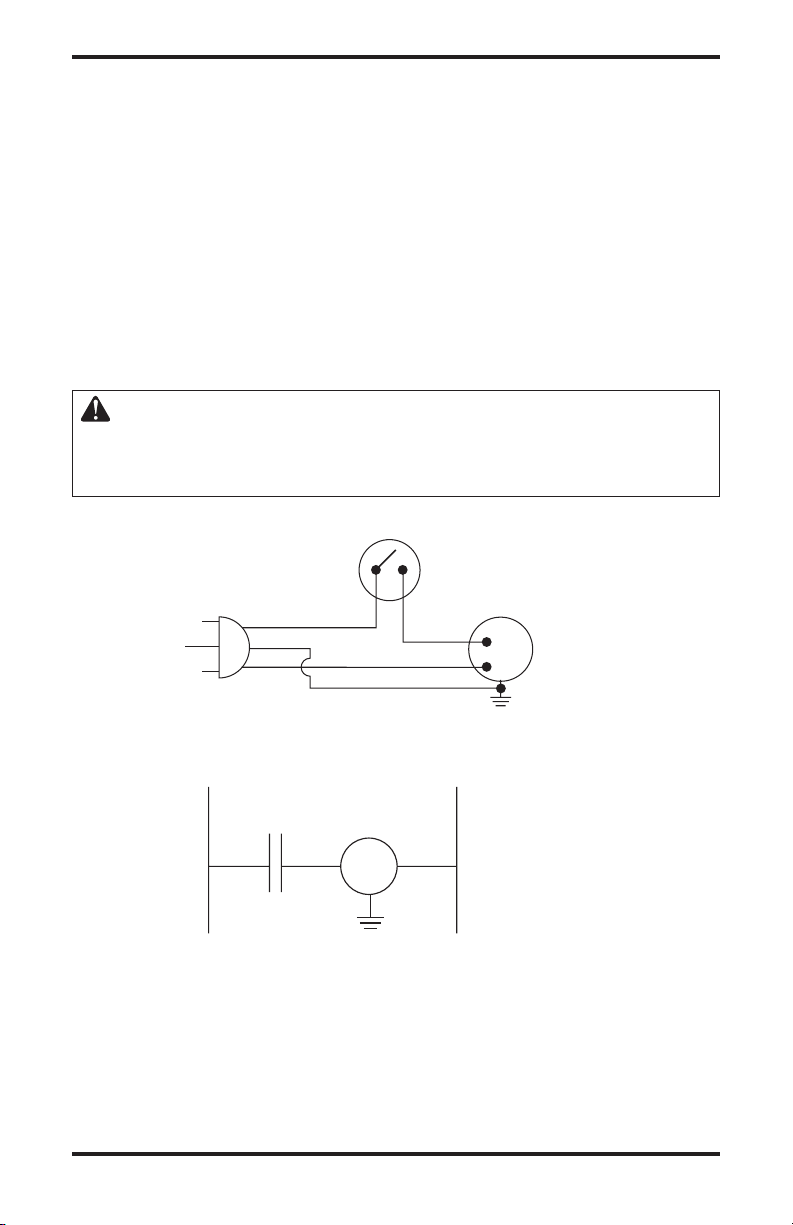
ESPECIFICACIONES
Thermostat
Sensor Switch/
Interruptor de sensor
de temperatura
White/Blanco
Green/Verde
11
0/115
V.
A.C.
(V.C.A.)
Blower Motor/
Motor del
ventilador
Black/Negro
Black/
Negro
Thermostat
Sensor Switch/
Interruptor de sensor
de temperatura
N/O
* If any of the original wire as supplied with the appliance must be replaced,
it must be replaced with type 105°C wire or its equivalent.
* En caso que se deba reemplazar alguno de los cables suministrados
originalmente con el calentador, utilice únicamente cable tipo 105°C u otro equivalente.
Line/
Línea
Neutral/
Neutro
White/
Blanco
Green/
Verde
Motor
Black/
Negro
Black/
Negro
LSL18NT, SL18NT y VSL18NT
• Gas natural
• 9,000/18,000 BTU/h (variable)
• Encendido piezoeléctrico o electrónico
• Configuración del regulador de presión 3" de c.a.
• Presión del gas de entrada* (pulg. de c.a.):
Máxima - 10.5", Mínima - 4"
• Peso
Calentador: 10.4 kg (23 lbs.)
De envío: 12.7 kg (28 lbs.)
LSL18PT, SL18PT y VSL18PT
• Propano o gas LP
• 9,000/18,000 BTU/h (variable)
• Encendido piezoeléctrico o electrónico
• Configuración del regulador de presión 10" de c.a.
• Presión del gas de entrada* (pulg. de c.a.):
Máxima - 14", Mínima - 11"
• Peso
Calentador: 10.4 kg (23 lbs.)
De envío: 12.7 kg (28 lbs.)
* Para efectos de ajustes de entrada
DIAGRAMAS DE CABLEADO
PRECAUCIÓN: marque todos los cables antes de desconectarlos.
Los errores en el cableado pueden ocasionar funcionamiento errático
y peligroso. Después de dar servicio al calentador compruebe que éste
funcione correctamente.
Diagrama de cableado
22
Diagrama eléctrico elemental
www.desatech.com
116292-01D

ACCESORIOS
Adquiera estos accesorios del calentador con el distribuidor local. Si él no puede proveer estos accesorios,
comuníquese con la Central de piezas (consulte la
página 26) o bien, llame a DESA Heating Products
al 1-866-672-6040 para obtener información de re
ferencia. También puede escribir a la dirección que
aparece al reverso de este manual.
VÁLVULA DE CIERRE DEL EQUIPO
GA5010
Para todos los modelos. Válvula de cierre del equipo
con rosca interna de 1/8 de pulgada tipo NPT.
PAQUETE DE ENCENDEDOR
ELECTRÓNICO - GA435 (no se
muestra)
Para todos los modelos con encendido piezoeléctrico. Proporciona un encendido del piloto más fácil.
SERVICIO TÉCNICO
Es posible que tenga preguntas adicionales acerca
de la instalación, el funcionamiento o la solución de
problemas. De ser así, póngase en contacto con el
departamento de servicio técnico de DESA Heating
Products al teléfono 1-866-672-6040. Al llamar
tenga a la mano los números de modelo y serie de
su calentador.
También puede visitar el sitio web de servicio técnico de
DESA Heating Products en www.desatech.com
.
PUBLICACIONES DE
SERVICIO
Puede adquirir un manual de servicio en la dirección
que se indica en el reverso de este manual. Envíe
un cheque de $5.00 a nombre de DESA Heating
Products.
PIEZAS DE REPUESTO
Nota: use sólo piezas de repuesto originales. Esto
protegerá la cobertura de su garantía para partes
reemplazadas con garantía.
PIEZAS CON GARANTÍA
Póngase en contacto con los distribuidores autoriza-
dos de este producto. Si no pueden proporcionarle las
piezas originales de repuesto, llame al departamento
de servicio técnico de DESA Heating Products al
1-866-672-6040.
Cuando llame a DESA Heating Products, tenga listo:
• su nombre
• su dirección
• los números de modelo y de serie del calentador
• la falla del calentador
• el tipo de gas utilizado (propano o gas LP o gas
natural)
• la fecha de compra
Generalmente, le pediremos que devuelva la parte
a la fábrica.
PIEZAS SIN GARANTÍA
Póngase en contacto con los distribuidores autorizados
de este producto. Si ellos no pueden proveer piezas
de repuesto originales, comuníquese con la
de piezas más cercana (consulte la página 26) o bien,
llame a DESA Heating Products al 1-866-672-6040
para obtener información de referencia.
Cuando llame a DESA Heating Products, tenga listo:
• el número de modelo del calentador
• el número de la pieza de repuesto
CONSEJOS DE
REPARACIONES
Cuando la presión del gas de entrada sea
demasiado baja:
• El piloto no permanecerá encendido
•
El quemador tendrá un retraso durante el encendido
• El calentador no producirá el calor especificado
• El suministro de propano o gas LP puede ser bajo
Es posible que considere que la presión del gas sea
demasiado baja. Si es así, comuníquese con el provee
dor local de gas natural o de propano o gas LP.
Central
-
116292-01D 23
www.desatech.com

CLASIFICACIÓN ILUSTRADA DE PIEZAS
2
4
1
5
6
8
9
10
11
12
13
14
17
18
19
20
15
7
21
22
32
23
28
29
30
31
16
33
24
3
25
26
27
AA
Battery
Positive
UP
AAA
Battery
Negative
UP
MODELOS LSL18NT, LSL18PT, SL18NT, SL18PT, VSL18NT Y VSL18PT
Batería tipo
24
www.desatech.com
como se muestra en
clase de encendido
electrónico usa su
AAA con el
polo negativo
hacia arriba
Instale la batería
la ilustración
(Verifique qué
calentador)
116292-01D
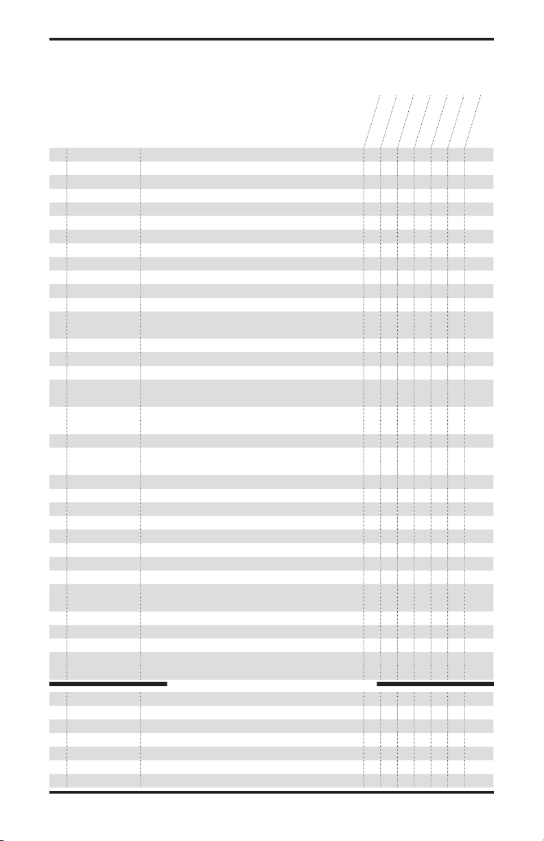
LISTA DE PIEZAS
Esta lista contiene las piezas reemplazables utilizadas en el calentador. Al hacer un pedido de piezas,
siga las instrucciones enumeradas en Piezas de repuesto en la página 23 de este manual.
N° N° DE PARTE DESCRIPCIÓN
LSL18NT
SL18NT
LSL18PT
VSL18NT
SL18PT
CANT.
VSL18PT
1 116591-01DE Rejilla pintada • • • • • • 1
2 116958-01 Puerta de plástico y cavidad de la puerta • • • • • • 1
3 117471-01 Blindaje de protección • • • • • • 1
4 116667-01CK Panel anterior • • • • • • 1
5 116392-01 Vidrio de acrílico oscuro • • • • • • 1
6 097159-04 Encendido piezoeléctrico • • 1
7 111435-01 Encendido electrónico • • • • 1
8 M50104-06 Buje corto • • • • • • 1
9 116276-01 Soporte de montaje del interruptor • • • • • • 1
10 101378-02 Interruptor de sensor de temperatura • • • • • • 1
11 116283-01
Panel de fibra • • • • • • 1
12 116544-01 Recubrimiento de fibra • • • • • • 1
13 116282-01 Quemador, natural • • • 1
116282-02 Quemador, propano o gas LP
• • • 1
14 116784-01 Protector de radiación • • • • • • 1
15 098249-01 Tuerca del piloto ODS • • • • • • 2
16 116280-01 Tubo de salida • • • • • • 1
17 110803-01 Piloto ODS, natural • • • 1
110803-02
Piloto ODS, propano o gas LP • • • 1
18 098271-09 Cable del encendedor • • 1
098271-11
Cable del encendedor • • • • 1
19 116679-01 Soporte del piloto • • • • • • 1
20 101004-08 Inyector, natural • • • 1
101004-10 Inyector, propano o gas LP • • • 1
21 097785-11 Junta • • • • • • 1
22 116528-01 Tubo del ventilador inferior • • • • • • 1
23 116286-01 Ventilador • • • • • • 1
24 116529-01 Tubo del ventilador superior • • • • • • 1
25 116270-01 Deflector de la parte superior • • • • • • 1
26 099066-02 Soporte de montaje • • • • • • 1
27 116267-01 Panel anterior • • • • • • 1
28 M11143-1 Buje para atenuar deformaciones • • • • • • 1
29 098522-28 Válvula de gas, natural • • • 1
098522-11
Válvula de gas, propano o gas LP • • • 1
30 102394-02 Soporte del control • • • • • • 1
31 116278-01 Tubo de entrada • • • • • • 1
32 099387-11 Tubo del piloto • • • • • • 1
33 099415-17 Regulador de gas, natural • • • 1
099415-22 Regulador de gas, propano o gas LP • • • 1
110186-01 Paquete de termopar • • • • • • 1
PIEZAS DISPONIBLES (NO SE MUESTRAN)
098219-41 Cable de alimentación • • • • • • 1
100642-05 Bolsa de ferretería • • • • • • 1
116360-01
116360-02
Etiqueta de encendido y advertencia (en Inglés)
Etiqueta de encendido y advertencia (en Español)
• • • • • • 1
• • • • • • 1
101584-08 Diagrama de cableado • • • • • • 1
116291-01
116292-01D 25
Etiqueta del control • • • • • • 1
www.desatech.com

CENTRALES DE PIEZAS
Estas Centrales de piezas son empresas privadas. Han aceptado dar asistencia a las necesidades de
nuestros clientes ofreciendo piezas de repuesto y accesorios originales.
Tool & Equipment, Co.
5 Manila Ave
Hamden, CT 06514-0322, EE.UU.
1-800-397-7553
203-248-7553
Parts Department
Portable Heater Parts
342 N. County Rd. 400 East
Valparaiso, IN 46383-9704, EE.UU.
Para todos los estados de EE.UU.
219-462-7441
1-888-619-7060
sales@portableheaterparts.com
techservice@portableheaterparts.com
FBD
1349 Adams Street
Bowling Green, KY 42103-3414, EE.UU.
270-846-1199
1-800-654-8534
Fax: 1-800-846-0090
franktalk@aol.com
Master Parts Dist.
1251 Mound Ave. NW
Grand Rapids, MI 49504-2672, EE.UU.
616-791-0505
1-800-446-1446
Fax: 616-791-8270
www.nbmc.com
Washer Equipment Co.
1715 Main Street
Kansas City, MO 64108-2195, EE.UU.
KS, MO, AR
816-842-3911
www.washerparts.com
East Coast Energy Products
707 Broadway
W Long Branch, NJ 07764-1542
732-870-8809
1-800-755-8809
www.njplaza.com/ecep
21st Century
2950 Fretz Valley Road
Perkasie, PA 18944-4034
215-795-0400
800-325-4828
Laporte’s Parts & Service
2444 N. 5th Street
Hartsville, SC 29550-7704, EE.UU.
843-332-0191
Parts Department
Cans Unlimited, Inc.
P.O. Box 645
Taylor, SC 29687-0013, EE.UU.
Para todos los estados de EE.UU.
803-879-3009
1-800-845-5301
cuisales@aol.com
26
www.desatech.com
116292-01D

NOTAS
______________________________________________________
______________________________________________________
______________________________________________________
______________________________________________________
______________________________________________________
______________________________________________________
______________________________________________________
______________________________________________________
______________________________________________________
______________________________________________________
______________________________________________________
______________________________________________________
______________________________________________________
______________________________________________________
______________________________________________________
______________________________________________________
______________________________________________________
______________________________________________________
______________________________________________________
______________________________________________________
______________________________________________________
______________________________________________________
______________________________________________________
______________________________________________________
______________________________________________________
______________________________________________________
______________________________________________________
______________________________________________________
______________________________________________________
______________________________________________________
______________________________________________________
______________________________________________________
______________________________________________________
______________________________________________________
116292-01D 27
www.desatech.com

116292 01
INFORMACIÓN DE GARANTÍA
GUARDE ESTA GARANTÍA
Modelo
N° de serie
Fecha de compra
Siempre especifique los números de modelo y de serie cuando se comunique con la fábrica.
Nos reservamos el derecho de modificar estas especificaciones en cualquier momento sin previo aviso. La única garantía
aplicable es nuestra garantía estándar por escrito. No otorgamos ninguna otra garantía, expresa o implícita.
GARANTÍA LIMITADA PARA PRODUCTOS NUEVOS Y
REACONDICIONADOS DE FÁBRICA
CALENTADORES DE GAS SIN VENTILACIÓN PARA USO
RESIDENCIAL
Productos nuevos:
en los materiales y mano de obra por dos (2) años a partir del día de la compra, siempre y cuando se haya operado y
dado mantenimiento de acuerdo con la instrucciones del fabricante. Estas garantías se extienden solamente al comprador
minorista original, cuando se proporciona un comprobante de compra.
Calentadores reacondicionados de fábrica:
contra cualquier defecto en los materiales y mano de obra por treinta (30) días a partir del día de la compra, siempre
y cuando se haya operado y dado mantenimiento de acuerdo con la instrucciones del fabricante. Estas garantías se
extienden solamente al comprador minorista original, cuando se proporciona un comprobante de compra.
Esta garantía cubre únicamente al comprador minorista original. Esta garantía cubre el costo de las piezas necesarias
para restaurar este calentador a sus condiciones correctas de funcionamiento y una cantidad compensatoria para mano
de obra cuando sea realizada por un centro de servicio autorizado de DESA Heating Products. Las piezas de garantía
SE DEBEN obtener por medio de los distribuidores autorizados de este producto y de DESA Heating Products quienes
proporcionarán las piezas de repuesto originales de fábrica. Si no se utilizan piezas de repuesto originales de fábrica,
esta garantía quedará anulada. Un instalador capacitado DEBE haber instalado el calentador de acuerdo con todos los
códigos locales e instrucciones incluidas con la unidad.
Esta garantía no se aplica a las piezas que no estén en su condición original debido al desgaste y ruptura normales, ni a las piezas
que fallen o se dañen como resultado del uso incorrecto, accidentes, falta de mantenimiento adecuado o defectos ocasionados
por la instalación incorrecta. Los viáticos, gastos de diagnóstico, mano de obra, transporte y todos los costos de naturaleza
similar que se relacionen con la reparación de un calentador defectuoso serán responsabilidad del propietario.
HASTA DONDE LO PERMITA LE LEY DE LA JURISDICCIÓN QUE REGULA LA VENTA DEL PRODUCTO,
ESTA GARANTÍA EXPLÍCITA EXCLUYE A TODAS Y CADA UNA DE LAS DEMÁS GARANTÍAS EXPLÍCITAS
Y LIMITA LA DURACIÓN DE TODAS Y CADA UNA DE LAS GARANTÍAS IMPLÍCITAS, INCLUSO LAS
GARANTÍAS DE MERCANTIBILIDAD E IDONEIDAD PARA UN PROPÓSITO PARTICULAR, A DOS (2) AÑOS
PARA TODOS LOS COMPONENTES A PARTIR DE LA FECHA DE LA PRIMERA COMPRA; Y EL PRESENTE
DOCUMENTO LIMITA LA RESPONSABILIDAD DE DESA HEATING PRODUCTS AL PRECIO DE COMPRA DEL
PRODUCTO, DE MANERA QUE DESA HEATING PRODUCTS NO SERÁ RESPONSABLE POR NINGÚN OTRO
DAÑO EN ABSOLUTO, LO QUE INCLUYE LOS DAÑOS INDIRECTOS, INCIDENTALES O EMERGENTES.
En algunos estados no se permiten las limitaciones en cuanto a la duración de las garantías implícitas o las exclusiones
o limitaciones de los daños incidentales o emergentes, de manera que es posible que la limitación anterior referente a
las garantías implícitas o la exclusión o limitación de daños no se aplique a usted.
Esta garantía le otorga derechos legales específicos y usted podría tener también otros derechos que varían de un
estado a otro.
Para obtener información sobre esta garantía, escriba a:
DESA Heating Products garantiza este calentador y cualquiera de sus partes contra cualquier defecto
DESA Heating Products garantiza este calentador y cualquiera de sus partes
Patente en trámite
2701 Industrial Drive
P.O. Box 90004
Bowling Green, KY 42102-9004
www.desatech.com
116292-01
Rev. D
08/05
NOT A UPC
 Loading...