

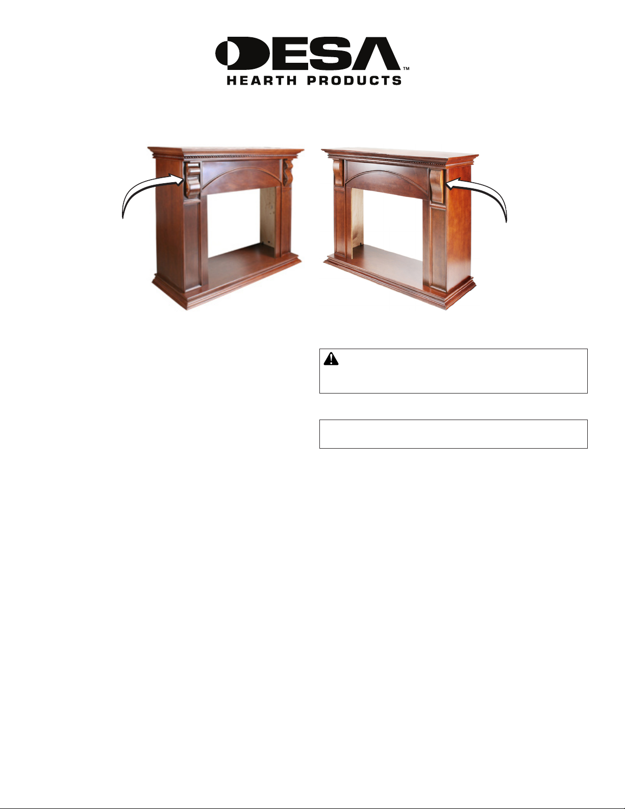
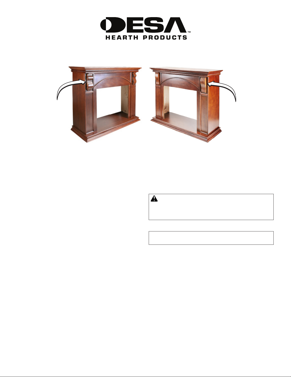
W32LS2 WALL MANTEL AND BASE
ASSEMBLY AND INSTALLATION INSTRUCTIONS
Shown with
Carved Corbels
IMPORTANT: Read entire instruction sheet before
assembling or installing mantel kit.
The W32LS2 mantel is only approved for use with
any DESA Heating Products 32" full size replace
system, or rebox and Dimplex electric full size re-
place. Do not use mantel with any other product.
This mantel kit contains the following:
• Mantel pieces - unassembled and marked as follows:
#1 Base
#2 Right Side with arrow
#3 Right Front Leg with arrow
#4 Left Side with arrow
#5 Left Front Leg with arrow
#6 Header with arrow
#7 Top
#8 Header Assembly Block (2 Pieces)
#11 Carved Corbels
#12 Smooth Corbels
• For use only with Dimplex Electric Fireplace
#8 Dimplex Filler Assembly Block (1 piece)
#9 Dimplex Electric Fireplace Filler Panel
#10 Dimplex Filler Panel Assembly Block (2 Pieces)
• Hardware Kit*
14 - Metal Brackets 118937-01
28 - Screws M6 x 12 mm (1/2") 121149-01
26 - Screws M6 x 30 mm (1 1/4") 121335-01
26 - Washers M6 121336-01
1 - Allen Wrench 121337-01
*Extra hardware may be included.
If any wood pieces are missing or damaged, contact the
dealer where you purchased this mantel for replacement.
If hardware is missing or damaged, contact DESA Heating
Products at 1-866-672-6040 for referral information. You can
also visit DESA Heating Products’ technical service web site
at www.desatech.com.
Shown with
Smooth Corbels
Note: Gather all mantel pieces together before assembling
mantel.
WARNING: Use only 1/2" screws to attach metal
angle brackets. Damage to mantel will result if other
screws are used for this purpose.
ASSEMBLING MANTEL
IMPORTANT: More than one person is required to assemble and lift mantel.
Estimated assembly time: 45 minutes.
When assembling mantel do not tighten screws completely
until told to do so. There should be some play in the pieces
to allow for proper alignment and best possible t. It is very
important that more than one person assemble mantel together.
Panels must be held in proper alignment to each other while
tightening screws to assure fewer gaps and proper surface
alignment. When tightening screws, do not over tighten. This
may cause threads to strip. For this reason, the supplied Al-
len wrench should be used rather than a power screwdriver.
Panels have threaded inserts installed at screw locations.
Screws should start and turn easily in threaded holes when
assembled according to instructions. Do not force screws
into holes.
IMPORTANT: There is a serial number label inside of right
side panel and on outside package. When calling to request
technical assistance or for replacement parts please have
that number ready.
CORBEL INSTALLATION
1. Mantel kit contains two sets of corbels, a carved set and
a smooth set. Determine which set you prefer. Discard
other set.
2. From back sides of leg fronts, attach corbels using two
1 1/4" screws and washers. See Figure 1, page 2.
www.desatech.com
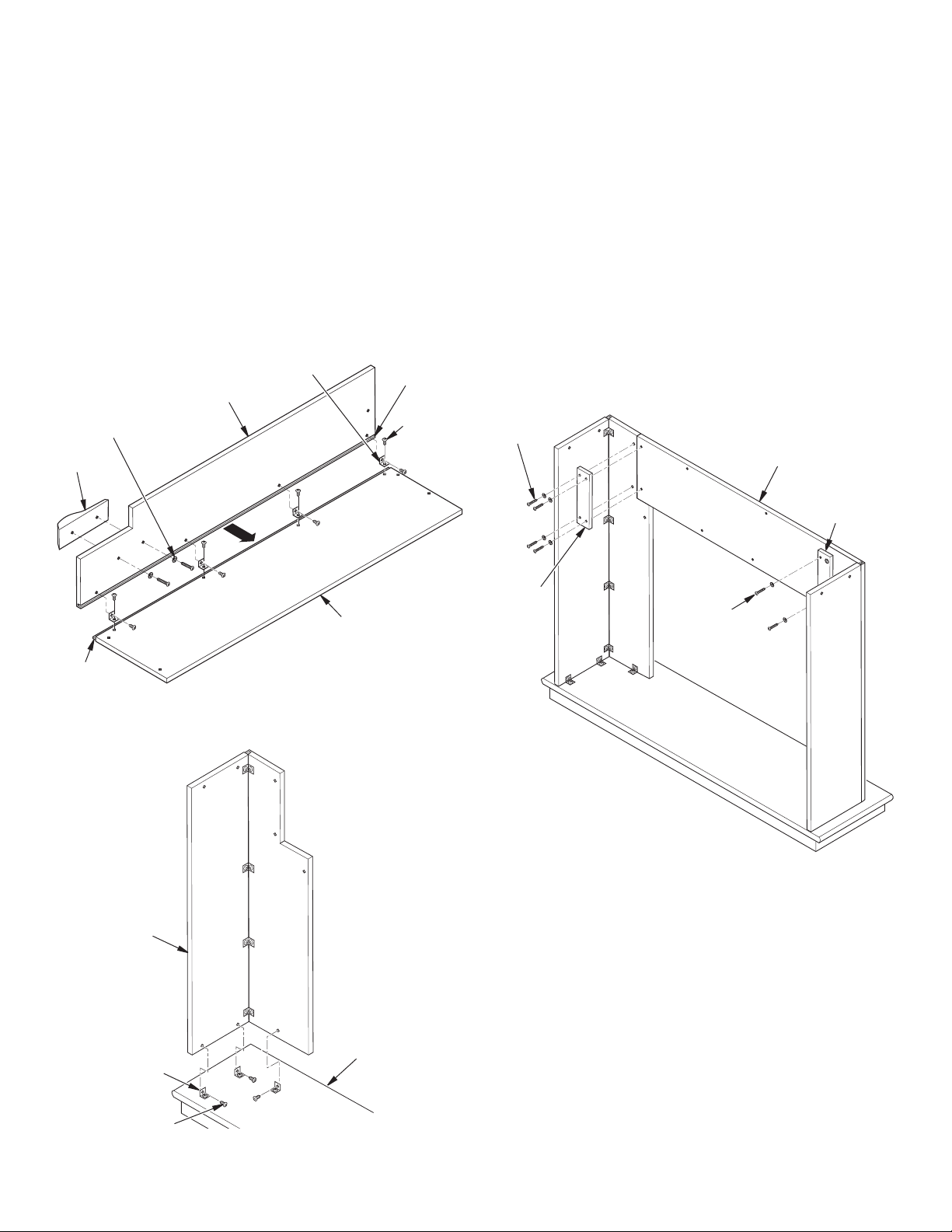
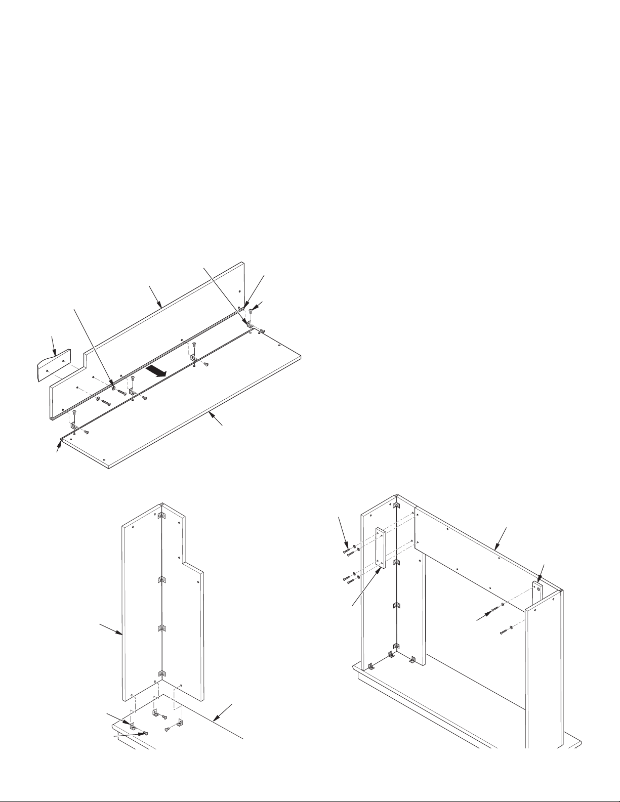
LEG ASSEMBLY
1. Lay right side panel (#2) face down on a soft surface to
avoid marking nish. Attach four brackets with 1/2" screws
to right side panel (#2) leaving screws slightly loose. Face
brackets out toward tongued side (see Figure 1). Place
right front leg over right side (#2) matching groove in leg
to tongue on side, as shown in Figure 1. Align threaded
holes with brackets on side. Start four 1/2" screws through
brackets. Align bottom of side and leg assembly so they
are ush with each other. Hold these pieces securely
while tightening (but not over tightening) screws.
2. Assemble left side (#4) and left leg (#5) as described in
step 1.
3. Attach 6 brackets to base (#1) at threaded hole locations
using 1/2" screws leaving screws loose. Face brackets
toward outside.
Bracket
Leg Front (#3)
1 1/4" Screw
with Washer
Groove in
Leg Front
1/2" Screw
4. Place right side/leg assembly on base and align threaded
holes with brackets. Start 1/2" screws through brackets
into threaded holes in side/leg assembly. Back of side/
leg assembly should be ush with back of base. Assure
alignment is correct and spaces are at a minimum and
tighten leaving screws slightly loose.
5. Assemble left side/leg assembly to base (#1) following
step #4.
HEADER ASSEMBLY
1. Start two 1 1/4" screws with washers through header assembly block (#8) into threaded inserts on right side of
mantel. Repeat for left side (see Figure 3).
2. With arrow pointing up, place header (#6) into position on
top of leg assemblies and against header assembly block
(#8) (see Figure 3). Start two 1 1/4" screws with washers
through header assembly blocks (#8) into threaded inserts in header. Hold header in proper alignment with leg
assemblies and tighten, leaving screws slightly loose.
1 1/4" Screw
with Washer
Corbel
Tongue on
Leg Side
Figure 1 - Leg Assemblies (right side shown)
Right
Side/Leg
Assembly
Leg Side (#2)
Header (#6)
Header
Assembly
Block (#8)
Header
Assembly
Block (#8)
Figure 3 - Attaching Header
1 1/4" Screw
with Washer
MANTEL TOP ASSEMBLY
Place mantel top (#7) on mantel assembly. Align back of top
with back of sides. Using four 1 1/4" screws with washers,
place two in each mantel side assembly (see Figure 4, page
3). With two 1 1/4" screws with washers, attach top to header.
Make sure all pieces are aligned properly and tighten, leaving
screws slightly loose.
Base (#1)
Bracket
1/2" Screw
Figure 2 - Leg Assembly to Base
2
www.desatech.com
121340-01B
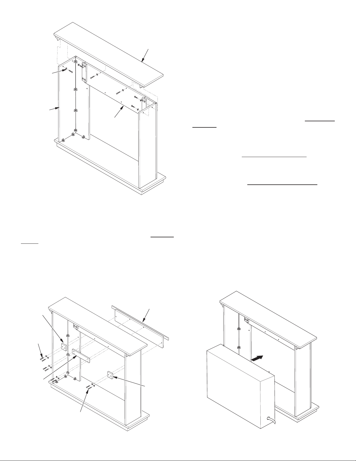
Mantel Top (#7)
3. Attach assembly blocks (#10) to sides of ller panel and
mantel side assemblies using two 1 1/4" screws with washers for each side. Do not tighten completely.
4. With one person holding parts in alignment, tighten
screws snuggly with Allen wrench provided. Do not over
tighten.
1 1/4" Screw
with Washer
Mantel Side
Assembly
Header
Figure 4 - Attaching Mantel Top
FOR DIMPLEX FIREPLACE USE ONLY
If you are installing a Dimplex Electric Fireplace in this mantel,
you will need to follow the instructions in this section. If you
are not installing a Dimplex Electric Fireplace, go to Finishing
Mantel and discard items #8, #9 and #10
1. Place Dimplex ller panel (#9) in position in front of mantel
with trim strip to outside covering joint between ller panel
and mantel (see Figure 5).
2. With one person holding ller panel in place, attach ller
assembly block (#8) to top of ller panel and bottom of
extension using four 1 1/4" screws with washers. Do not
completely tighten screws.
FINISHING MANTEL
Starting with left side leg assembly, tighten screws using Allen
wrench provided. Tighten screws on the right side leg assembly,
header, top assembly and base. When using Dimplex ller
panel, align and tighten at same time as header.
GAS FIREPLACE INSTALLATION
1. Fireplace should be fully assembled. See Assembling
Fireplace in replace owner’s manual.
2. Place mantel base close to installation location. See re-
place owner’s manual for installation clearances. Leave
enough room to insert replace from back of mantel.
3. Install gas line. See Connecting to Gas Supply in replace
owner’s manual. Remember to leave access to the gas
shutoff valve somewhere on the base or where it is ac-
cessible to the user.
4. Check for leaks. See Checking Gas Connections in re-
place owner’s manual.
5. Position replace inside mantel (see Figure 6). Carefully
position gas lines. Important: Use caution when positioning replace on base. Base may scratch easily. Make
sure replace is in proper position within mantel opening
before continuing with installation.
6. Fireplace with louver door: Lower bottom louver door.
Use two screws provided in hardware package and attach
replace to wooden base. Close louver door.
Fireplace with xed louver: Before installing logs or
burner assembly (see owner’s manual) remove screws
securing oor to assembly. Lift oor for access to bottom of replace. Use two screws provided in replace
hardware package and attach replace base to wooden
base. Reinstall oor with screws removed previously.
Dimplex Filler
Assembly
Block (#10)
1 1/4" Screw
with Washer
Dimplex
Filler
Assembly
Block (#8)
Figure 5 - Attaching Dimplex Filler Panel
121340-01B
1 1/4" Screw
with Washer
Dimplex Filler
Panel (#9)
Dimplex
Filler
Assembly
Block (#10)
www.desatech.com
Figure 6 - Installing Fireplace
3
7. If mantel trim that came with your replace has not yet
been assembled, see Assembling Perimeter Trim. Place
metal trim on shoulder screws. Firmly snap trim assembly
over shoulder screws on replace.
8. Carefully push mantel and base into position against
wall.
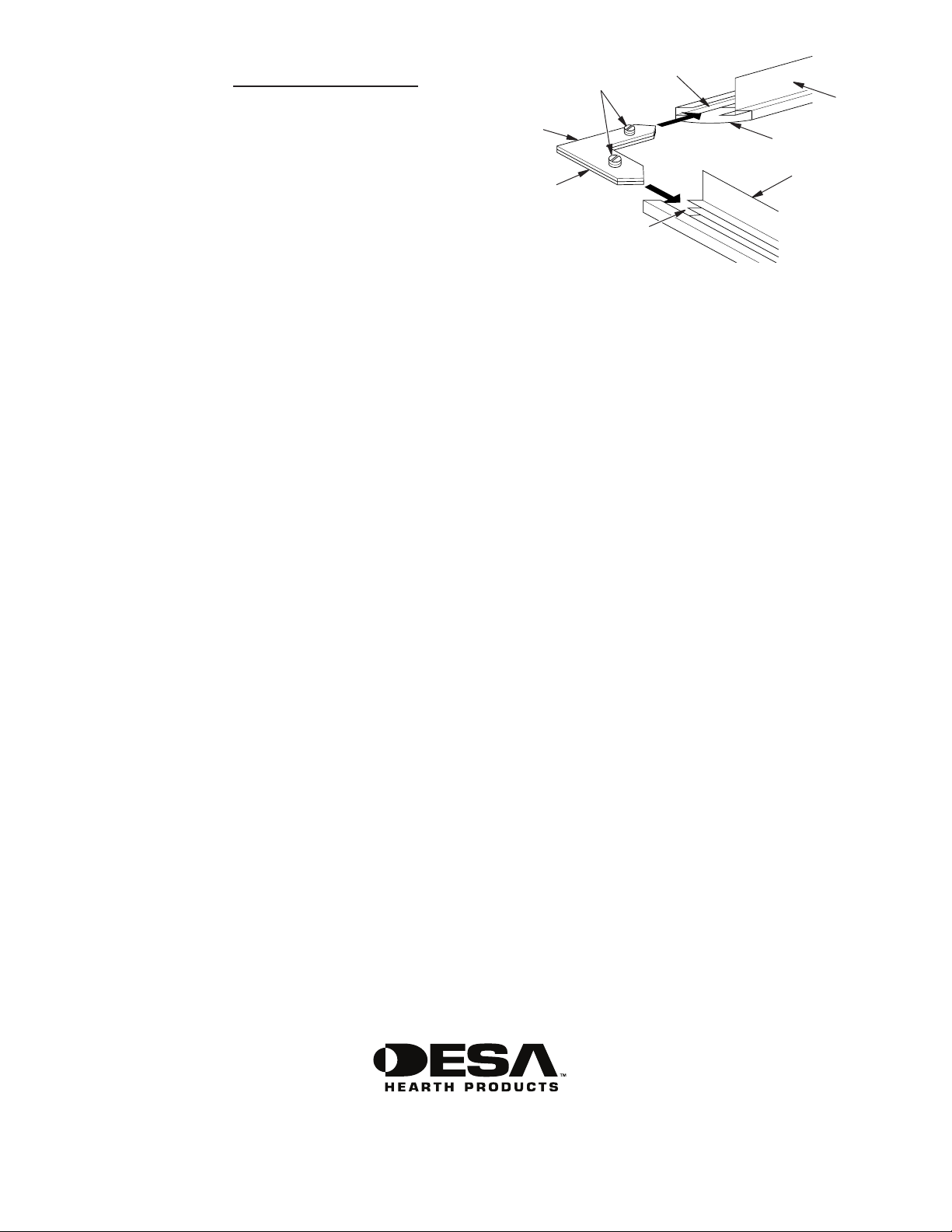
ASSEMBLING PERIMETER TRIM (If Supplied
with Gas Fireplace)
1. Remove packaging from three pieces of metal trim.
2. Locate two adjusting plates with set screws, and two
shims in the hardware packet.
3. Align shim under adjusting plate as shown in Figure 7.
4. Slide one end of adjusting plate/shim in slot on mitered
edge of top trim (see Figure 7).
5. Slide other end of adjusting plate/shim in slot on mitered
edge of side trim (see Figure 7).
6. While rmly holding edges of trim together, tighten both
set screws on the adjusting plate with slotted screwdriver.
7. Repeat steps 2 through 6 for other corner.
Set Screws
Adjusting
Plate
Shim
Figure 7 - Assembling Trim
Slot
Top Trim
Mitered Edge
Side Trim
Slot
ELECTRIC FIREPLACE INSTALLATION
This mantel can be used with Dimplex 32" Electric Fireplace.
Electric replaces install from the front of mantel. To install
electric replace see replace instruction manual. Use caution when positioning replace on base. Base may scratch
easily.
2701 Industrial Drive
P.O. Box 90004
Bowling Green, KY 42102-9004
www.desatech.com
1-866-672-6040
121340-01
Rev. B
05/07

BASE Y REPISA DE CHIMENEA PARA PARED W32LS2
INSTRUCCIONES DE ENSAMBLE E INSTALACIÓN
Se muestra
con ménsulas
esculpidas
IMPORTANTE: lea toda la hoja de instrucciones antes de
ensamblar o instalar el paquete de repisa de chimenea.
La repisa de chimenea W32LS2 está aprobada sólo para
su uso con cualquier sistema de chimenea de tamaño
completo 32" DESA o chimeneas eléctricas de tamaño
completo Dimplex.
Este paquete de repisa de chimenea contiene lo siguiente:
• Piezas de la repisa de chimenea: sin ensamblar y marcadas
como se indica a continuación:
nº 1 Base
nº 2 Lateral derecho nº 2 con echa
nº 3 Columna anterior derecha nº 3 con echa
nº 4 Lateral izquierdo nº 4 con echa
nº 5 Columna anterior izquierda nº 5 con echa
nº 6 Cabecera nº 6 con echa
nº 7 Parte superior nº 7
nº 8 Bloque de ensamble de cabecera (2 piezas)
nº 11 Ménsulas esculpidas
nº 12 Ménsulas de perl suave
• Para usar sólo con chimenea eléctrica Dimplex
nº 8 Bloque de ensamble de relleno Dimplex (1 pieza)
nº 9 Panel de relleno de chimenea eléctrica Dimplex
nº 10 Bloque de ensamble de panel de relleno (2 piezas)
• Accesorios de ferretería*
14 soportes metálicos 118937-01
28 tornillos M6 x 12 mm (1/2") 121149-01
22 tornillos M6 x 30 mm (1 1/4") 121335-01
22 arandelas M6 121336-01
1 llave Allen 121337-01
* Es posible que se incluya ferretería adicional.
Si alguna pieza de madera faltase o estuviese rota, contacte
a la tienda donde adquirió la repisa de chimenea para su
reemplazo. Si le falta material de ferretería o está dañado,
contacte a DESA Heating Products al 1-866-672-6040 para
obtener información de referencia. También puede visitar el
sitio web de servicio técnico de DESA Heating Products en
www.desatech.com.
www.desatech.com
Se muestra
con ménsulas
de perl suave
Nota: reúna todas las piezas de la repisa de chimenea antes
de ensamblarla.
ADVERTENCIA: use sólo tornillos de 1/2" para jar
los soportes metálicos angulares. Si se utilizan otros
tornillos para este n, la repisa de chimenea resultará
dañada.
ENSAMBLE DE LA REPISA DE CHIMENEA
IMPORTANTE: se requiere de más de una persona para
ensamblar y levantar la repisa de chimenea.
Tiempo estimado de ensamblaje: 45 minutos.
Al ensamblar la repisa, no apriete por completo los tornillos
mientras no se le indique que lo haga. Las piezas deberán
tener cierto juego para poder darle la alineación correcta y
el mejor encaje posible. Es de suma importancia ensamblar
la repisa de chimenea con la ayuda de otra persona. Los
paneles se deben mantener correctamente alineados entre
sí mientras se aprietan los tornillos para que quede el menor
espacio libre posible y la supercie quede bien alineada.
Cuando apriete los tornillos, no lo haga en exceso. Ello podría dañar las roscas. Por este motivo, deberá usar la llave
Allen en vez de un destornillador eléctrico. Los paneles tienen piezas de inserción roscadas instaladas en los lugares
donde van los tornillos. Los tornillos deben comenzar a girar
con facilidad en los oricios roscados cuando el ensamble se
efectúa según las instrucciones. No fuerce los tornillos para
introducirlos en los oricios.
IMPORTANTE: hay una etiqueta con el número de serie en
el interior del panel lateral derecho y en el paquete externo.
Cuando solicite asistencia técnica o pida piezas de repuesto,
tenga a la mano este número.

INSTALACIÓN DE LA MÉNSULA
1. El paquete de la repisa de chimenea contiene dos con-
juntos de ménsulas, uno esculpido y otro de perl suave.
Determine cuál conjunto preere. Deshágase del otro
conjunto.
2. Desde la parte trasera de las cubiertas anteriores de los
tramos laterales, una las ménsulas utilizando dos tornillos
de 1 1/4" y arandelas. Consulte la gura 1, en la página 2.
ENSAMBLE DE COLUMNA
1. Apoye el panel lateral derecho (nº 2) hacia abajo sobre
una supercie suave para no dejar marcas en el acabado.
Fije cuatro soportes con tornillos de 1/2" el panel lateral
derecho (nº 2) dejando los tornillos un poco sueltos.
Coloque los soportes hacia afuera, hacia el lado de len-
güeta (consulte la gura 1). Coloque la columna anterior
derecha sobre el lado derecho (nº 2) haciendo coincidir
el canal en la columna con la lengüeta en el lateral, tal
Parte anterior de
la columna (nº 3)
Tornillo de 1 1/4"
con arandela
Ménsula
Lengüeta en
el lateral de la
columna
Figure 1 - Ensambles del tramo (se muestra el lado derecho)
Soporte
Canal en la
parte anterior
de la columna
Tornillo
de 1/2"
Lateral de la
columna (nº 2)
como se indica en la gura 1. Alinee los oricios roscados
a los soportes al costado. Pase cuatro tornillos de 1/2" a
través de los soportes. Alinee la parte inferior del ensamble de lateral y columna para que queden parejos entre
sí. Sostenga estas piezas alineadas con rmeza mientras
aprieta los tornillos (pero no apriete en exceso).
2. Ensamble el lado izquierdo (nº 4) y la columna izquierda
(nº 5) según se describe en el paso 1.
3. Fije 6 soportes a la base (nº 1) en el lugar donde se en-
cuentran los oricios roscados usando tornillos de 1/2",
dejándolos ojos. Coloque los soportes hacia afuera.
4. Coloque el ensamble derecho de lateral y columna sobre
la base y alinee los oricios roscados a los soportes. Pase
los tornillos de 1/2" a través de los soportes para colo-
carlos en los oricios roscados del ensamble de lateral
y columna. La parte posterior del ensamble de lateral y
columna debe quedar pareja con la parte posterior de la
base. Verique que la alineación sea correcta y que los
espacios libres sean mínimos, luego apriete los tornillos
dejándolos ligeramente ojos.
5. Ensamble el conjunto izquierdo de lateral y columna a
la base (nº 1) según el paso nº 4.
ENSAMBLE DE LA CABECERA
1. Pase dos tornillos de 1 1/4" con arandelas a través del
bloque de ensamble de la cabecera (nº 8), introduciéndolos en las piezas de inserción roscadas sobre el lado
derecho de la repisa de chimenea. Repita la operación
en el lado izquierdo (consulte la gura 3).
2. Con la echa hacia arriba, ubique la cabecera (nº 6) en
su sitio sobre la parte superior de los montajes de las
columnas y contra el bloque de ensamble de la cabecera
(nº 8) (consulte la gura 3). Pase dos tornillos de 1 1/4" con
arandelas a través de los bloques de ensamble de la cabecera (nº 8) para introducirlos en las piezas de inserción
roscadas de la cabecera. Sostenga la cabecera correctamente alineado con los ensambles de las columnas y
apriete, dejando los tornillos ligeramente ojos.
Tornillo de 1 1/4"
con arandela
Cabecera (nº 6)
Ensamble
derecho
de lateral y
columna
Soporte
Tornillo de 1/2"
Figura 2 - Ensamble de columna a la base
2
Base (nº 1)
Bloque de
ensamble de
la cabecera
(nº 8)
www.desatech.com
Bloque de
ensamble de la
cabecera (nº 8)
Tornillo de
1 1/4" con
arandela
Figura 3 - Fijación de la cabecera
121340-01B

ENSAMBLE SUPERIOR DE LA REPISA DE CHIMENEA
Coloque la parte superior de la repisa de chimenea (nº 7)
sobre el ensamble de la misma. Alinee el respaldo de la parte
superior con la parte posterior de los laterales. Mediante
cuatro tornillos de 1 1/4" con arandelas, coloque dos en cada
lateral del ensamble de la repisa de chimenea (consulte la
gura 4). Mediante dos tornillos de 1 1/4" con arandelas, je
la parte superior a la cabecera. Compruebe que todas las
piezas estén correctamente alineadas y apriete, dejando los
tornillos ligeramente ojos.
Bloque de
ensamble
de relleno
Dimplex
(nº 10)
Tornillo de
1 1/4" con
arandela
Panel de relleno
Dimplex (nº 9)
Parte superior de la repisa
de chimenea (nº 7)
Tornillo de
1 1/4" con
arandela
Ensamble
del lateral de
la repisa de
chimenea
Figura 4 - Cómo fijar la parte superior de la repisa
Cabecera
SÓLO PARA USAR CON LA CHIMENEA ELÉCTRICA
DIMPLEX
Si está instalando una chimenea eléctrica Dimplex en esta
repisa, necesitará seguir las instrucciones de esta sección.
Si no está instalando la chimenea eléctrica Dimplex, vaya a
la sección Acabado de la repisa de chimenea y deshágase
de los artículos nº 8, 9 y 10
1. Coloque el panel de relleno Dimplex (nº 9) en su sitio,
sobre la parte anterior de la repisa con la banda de
adorno hacia afuera, cubriendo la junta entre el panel y
la repisa (consulte la gura 5).
2. Mientras una persona sostiene el panel de relleno en su
sitio, je el bloque de ensamble de relleno (nº 8) sobre
la parte superior del panel de relleno y la parte inferior
de la extensión mediante cuatro tornillos de 1 1/4" con
arandelas. No apriete los tornillos por completo.
3. Fije los bloques del ensamble (nº 10) a los laterales del
panel de relleno y a los ensambles laterales de la repisa
mediante dos tornillos de 1 1/4" con arandelas por cada
lado. No apriete los tornillos por completo.
4. Mientras una persona sostiene las piezas alineadas,
apriete bien los tornillos con la llave Allen provista. No
los apriete demasiado.
Bloque de
ensamble
de relleno
Dimplex
(nº 8)
Tornillo de 1 1/4"
con arandela
Figura 5 - Cómo jar el panel de relleno Dimplex
Bloque de
ensamble
de relleno
Dimplex
(nº 10)
ACABADO DE LA REPISA DE CHIMENEA
Comience por el ensamble de la columna del lado izquierdo,
apretando los tornillos con la llave Allen provista. Apriete los
tornillos del ensamble de la columna del lado derecho, la
cabecera, el ensamble de la parte superior y la base. Cuando
use el panel de relleno Dimplex, alinee y apriete al mismo
tiempo que la cabecera.
INSTALACIÓN DE LA CHIMENEA A GAS
1. La chimenea debe estar totalmente ensamblada. Consulte la sección Ensamble de la chimenea en el manual
del propietario de la chimenea.
2. Coloque la base de la repisa de chimenea cerca del lugar
donde se realizará la instalación. Consulte en el manual
del propietario de la chimenea las distancias mínimas
para la instalación. Deje suciente espacio para insertar
la chimenea desde la parte posterior de la repisa.
121340-01B
www.desatech.com
Figura 6 - Instalación de la chimenea
3

3. Instale la línea de gas. Consulte la sección Conexión
al suministro de gas en el manual del propietario de la
chimenea. Recuerde dejar acceso para la válvula de
cierre del gas en alguna parte de la base o donde sea
accesible para el usuario.
4. Revise que no haya fugas. Consulte la sección Revisión
de las conexiones de gas en el manual del propietario
de la chimenea.
5. Coloque la chimenea dentro de la repisa (consulte la gura
6, página 3). Con cuidado coloque las líneas de gas.
IMPORTANTE: tenga cuidado al colocar la chimenea
sobre la base. La base se podría raspar fácilmente.
Compruebe que la chimenea esté en la posición correcta
dentro de la abertura de la repisa antes de proseguir con
la instalación.
6. Chimenea con puerta de ventila: baje la puerta con
ventila inferior. Use dos tornillos provistos en el equipo de
ferretería y je la chimenea a la base de madera. Cierre
la puerta de ventila.
Chimenea con ventila ja: antes de instalar los leños
o el ensamble del quemador (consulte el manual del
propietario), retire los tornillos que aseguran el suelo al
ensamble. Levante el suelo para tener acceso a la parte
inferior de la chimenea. Use dos tornillos que vienen en
el equipo de ferretería de la chimenea y fíjela a la base
de madera. Vuelva a instalar el suelo con los tornillos
que quitó anteriormente.
7. Si el adorno de repisa que acompaña la chimenea todavía
no ha sido ensamblado, consulte la sección Ensamble del
marco de adorno. Coloque el adorno metálico sobre los
tornillos con pivotes. Con rmeza, encaje el ensamble del
adorno sobre los tornillos con pivote en la chimenea.
8. Empuje cuidadosamente la repisa y la base contra la pared para que queden en el sitio que les corresponde.
ENSAMBLE DEL MARCO DE ADORNO (Si
acompañara a la chimenea a gas)
1. Retire el embalaje de las tres piezas del adorno metálico.
2. Localice dos placas de ajuste con su juego de tornillos
y dos bases para nivelar en el paquete de piezas.
3. Alinee la base para nivelar debajo de la placa de ajuste
como se muestra en la gura 7.
4. Deslice un extremo de la placa de ajuste y base para
nivelar en la ranura del borde angular de la parte superior
del adorno de la chimenea (consulte la gura 7).
5. Deslice el otro extremo de la placa de ajuste y base para
nivelar en la ranura del borde angular del adorno de la
chimenea (consulte la gura 7).
6. Mientras sujeta rmemente los bordes del adorno unidos,
apriete los dos tornillos jos de la placa de ajuste con un
destornillador plano.
7. Repita los pasos 2 a 6 para la otra esquina.
Tornillos
de jación
Placa de
ajuste
Base para
nivelar
Ranura
Figura 7 - Armado del adorno
Ranura
Parte
superior
del adorno
Borde angular
Lado del
adorno
INSTALACIÓN DE CHIMENEA ELÉCTRICA
Esta repisa se puede usar con la chimenea eléctrica Dimplex
de 32". Las chimeneas eléctricas se instalan por la parte
anterior de la repisa. Para instalar una chimenea eléctrica
consulte el manual de instrucciones correspondiente. Tenga
cuidado al colocar la chimenea sobre la base. La base se
podría raspar fácilmente.
2701 Industrial Drive
P.O. Box 90004
Bowling Green, KY 42102-9004, EE.UU.
www.desatech.com
1-866-672-6040
121340-01
Rev. B
05/07
Manteau et base de foyer mural W32LS2
INSTRUCTIONS D'ASSEMBLAGE ET D'INSTALLATION
Illustré avec
moulure ajourée
IMPORTANT : lisez le manuel d'instructions au complet avant d'assembler et d'installer le prêt-à-monter
du manteau de foyer.
L'utilisation du manteau W32LT est uniquement
approuvée pour les systèmes de foyer classiques
de 81 cm (32 po) de DESA Heating Products, ou les
chambre de combustion et les foyers électriques
classiques Dimplex. N'utilisez pas ce manteau avec
d'autres produits.
Ce prêt-à-monter du manteau de foyer contient ce qui suit :
• Pièces de manteau prêtes-à-assembler et indiquées
comme suit :
No 1 Base
No 2 Côté droit avec flèche
No 3 Support latéral avant droit avec flèche
No 4 Côté gauche avec flèche
No 5 Support latéral avant gauche avec flèche
No 6 Linteau avec flèche
No 7 Tablette
No 8 Bloc entretoise de linteau (2 pièces)
No 11 Moulure ajourée
No 12 Moulure lisse
• À utiliser uniquement avec les foyers électriques Dimplex
No 8 Bloc entretoise Dimplex (1 pièce)
No 9 Panneau entretoise pour foyer électrique Dimplex
No 10 Bloc de panneau entretoise Dimplex (2 pièces)
• Prêt-à-monter de quincaillerie*
14 - Équerres de fixation métalliques
28 - Vis M6 x 12 mm (1/2 po)
26 - Vis M6 x 30 mm (1 1/4 po)
26 - Rondelles M6
1 - Clé hexagonale
* Des pièces de quincaillerie supplémentaires peuvent être
inclues.
S'il manque des pièces de bois ou si des pièces de bois sont
endommagées, contactez le marchand de ce manteau de
www.desatech.com
Illustré avec
moulure lisse
foyer pour obtenir des pièces de rechange. S'il manque des
pièces de quincaillerie ou si des pièces de quincaillerie sont
endommagées, contactez DESA Heating Products au 1 866
672 6040 pour plus de renseignements. Vous pouvez aussi
visiter le site web du service technique de DESA Heating
Products à l'adresse www.desatech.com.
Remarque : rassemblez toutes les pièces du manteau de
foyer avant de l'assembler.
AVERTISSEMENT : utilisez uniquement les vis de
12 mm (1/2 po) pour monter les équerres de fixation
métalliques. Le manteau risque d'être endommagé si
d'autres vis sont utilisées pendant l'assemblage.
ASSEMBLAGE DU MANTEAU DE FOYER
IMPORTANT : il faut plus d'une personne pour assembler et soulever le manteau.
Durée d'assemblage estimée : 45 minutes.
Pendant l'assemblage du manteau, ne serrez pas les vis à
fond à moins que ce ne soit indiqué. Il devrait y avoir sufsamment d'espace entre les pièces pour permettre un alignement correct et le meilleur montage possible. Veillez à ce que
plusieurs personnes participent à l'assemblage du manteau.
Les panneaux doivent être soutenus de manière à ce qu'ils
s'alignent correctement pendant que vous serrez les vis pour
assurer le moins d'espacement et un alignement correct sur
toute la surface. Pendant que vous serrez les vis, ne les ser-
rez pas à fond. Ceci pourrait arracher les letages. Pour cette
raison, utilisez la clé hexagonale fournie au lieu d'un tournevis
électrique. Les panneaux ont des chevilles letées installées
dans les emplacements des vis. Si vous suivez les instructions
d'assemblage, les vis doivent s'insérer et se visser facilement
dans les trous letés. Ne forcez pas les vis dans les trous.
IMPORTANT : une étiquette avec un numéro de série se trouve
à l'intérieur du côté droit du panneau et à l'extérieur de l'emballage. Référez-vous à ce numéro de série lorsque vous faites une
demande d'assistance technique ou de pièces de rechange.
INSTALLATION DES MOULURES
1. Le prêt-à-monter du manteau de foyer contient deux
paires de moulures, une paire ajourée et une paire lisse.
Déterminez celle que vous préférez. Débarrassez-vous
de l'autre paire.
2. À partir des côtés arrière des devants des supports la-
téraux, xez les moulures à l'aide de deux vis de 3,2 cm
(1 1/4 po) et des rondelles. Voir gure 1.
ASSEMBLAGE DES SUPPORTS LATÉRAUX
1. Placez le panneau du côté droit (no 2) face en dessous
sur une surface coussinée pour éviter toute égratignure
du fini. Montez quatre équerres de fixation avec les vis
de 12 mm (1/2 po) sur le panneau du côté droit (no 2)
en laissant les vis un peu desserrées. Les équerres de
fixation doivent faire face au côté de la languette (voir
figure 1). Placez le support latéral du côté droit sur le côté
droit (no 2) en faisant correspondre la rainure du support
Équerre de
Avant du support
latéral (no 3)
Vis de 3,2 cm
(1 1/4 po) avec
rondelle
Moulure
Languette
sur le côté du
support latéral
Figure 1 - Assemblages des support latéraux (côté droit illustré)
fixation
Côté du support
latéral (no 2)
Rainure dans
le côté du
support latéral
Vis de
12 mm
(1/2 po)
latéral à la languette sur le côté, comme illustré à la figure
1. Alignez les trous filetés avec les équerres sur le côté.
Insérez quatre vis de 12 mm (1/2 po) dans les équerres
de fixation. Alignez la base de l'assemblage des côtés
et du support latéral pour qu'ils s'affleurent. Maintenez
ces pièces fermement pendant que vous serrez (mais
ne serrez pas à fond) les vis.
2. Assemblez le côté gauche (no 4) et le support latéral (no
5) comme indiqué à l'étape 1.
3. Montez 6 équerres de fixation sur la base (no 1) sur les
emplacements des trous filetés en utilisant les vis de 12 mm
(1/2 po) et en les laissant un peu desserrées. Les équerres
de fixation doivent faire face à l'extérieur.
4. Placez l'assemblage du côté et du support latéral droits
sur la base et alignez les trous filetés sur les équerres.
Faites passer les vis de 12 mm (1/2 po) par les équerres
de fixation et dans les trous filetés de l'assemblage du
côté et du support latéral. L'arrière de l'assemblage du
côté et du support latéral doit être affleuré à l'arrière de
la base. Assurez-vous que l'alignement est correct, qu'il
y a peu d'espacement et serrez les vis en les laissant un
peu desserrées.
5. Montez l'assemblage du côté et du support latéral gauches sur la base (no 1) en suivant l'étape 4.
ASSEMBLAGE DU LINTEAU
1. Insérez deux vis de 3,2 cm (1 1/4 po) et des rondelles
dans le bloc entretoise du linteau (no 8) dans les chevilles
filetées sur le côté droit du manteau. Répétez pour le côté
gauche (voir figure 3).
2. Avec la flèche pointant vers le haut, positionnez le linteau (no 6) au-dessus des assemblages des panneaux
latéraux et contre le bloc entretoise du linteau (no 8) (voir
figure 3). Faites passer deux vis de 3,2 cm (1 1/4 po) et
des rondelles par les blocs entretoise du linteau (no 8)
et dans les chevilles filetées du linteau. Maintenez le
linteau complètement aligné sur les assemblages des
supports latéraux et serrez en laissant les vis un peu
desserrées.
Vis de 3,2 cm
(1 1/4 po) avec
rondelle
Linteau (no 6)
Assemblage
du côté et
du panneau
latéral droits
Équerre
de fixation
Vis de 12 mm
(1/2 po)
Figure 2 - Montage du support latéral sur la base
2
Base (no 1)
Bloc
entretoise
de linteau
(no 8)
www.desatech.com
Bloc
entretoise de
linteau (no 8)
Vis de 3,2 cm
(1 1/4 po) avec
rondelle
Figure 3 - Pose du linteau
121340-01B

ASSEMBLAGE DE LA TABLETTE DU
MANTEAU DE FOYER
Placez la tablette du manteau (no 7) sur l'assemblage du
manteau. Alignez l'arrière de la tablette sur l'arrière des côtés.
En utilisant quatre vis de 3,2 cm (1 1/4 po) et des rondelles,
placez-en deux dans chaque assemblage de côté de manteau
(voir figure 4). En utilisant deux vis de 3,2 cm (1 1/4 po) et des
rondelles, fixez la tablette au linteau. Assurez-vous que toutes
les pièces sont alignées correctement et serrez en laissant
les vis un peu desserrées.
Tablette du
manteau (no 7)
Bloc
entretoise
Dimplex
(no 10)
Vis de 3,2 cm
(1 1/4 po) avec
rondelle
Bloc
entretoise
Dimplex
(no 8)
Panneau entretoise
Dimplex (no 9)
Bloc
entretoise
Dimplex
(no 10)
Vis de
3,2 cm
(1 1/4 po)
avec
rondelle
Assemblage
des côtés
du manteau
Figure 4 - Montage de la tablette du manteau
Linteau
POUR LES FOYERS DIMPLEX UNIQUEMENT
Si vous installez un foyer électrique Dimplex dans ce manteau, vous avez besoin de suivre les instructions dans cette
section. Si vous n'installez pas de foyer électrique Dimplex,
reportez-vous à Fin de l'installation du manteau de foyer et
débarrassez-vous des articles no 8, 9 et 10.
1. Placez le panneau entretoise Dimplex (no 9) en position
devant le manteau avec une baguette de garniture sur le
joint de couverture extérieur entre le panneau entretoise
et le manteau (voir figure 5).
2. Tandis qu'une personne maintient en place le panneau
entretoise, fixez le bloc entretoise (no 8) au dessus du
panneau entretoise et à la base du support du linteau en
utilisant quatre vis de 3,2 cm (1 1/4 po) et des rondelles.
Ne serrez pas les vis à fond.
3. Fixez les blocs entretoise (no 10) aux côtés du panneau
entretoise et aux assemblages des côtés du manteau en
utilisant deux vis de 3,2 cm (1 1/4 po) et des rondelles de
chaque côté. Ne serrez pas les vis à fond.
4. Tandis qu'une personne maintient les parties alignées,
serrez les vis avec la clé hexagonale fournie. Ne serrez
pas les vis à fond.
Vis de 3,2 cm
(1 1/4 po) avec
rondelle
Figure 5 - Montage du panneau entretoise Dimplex
FIN DE L'INSTALLATION DU MANTEAU DE FOYER
En commençant par l'assemblage du support latéral du côté
gauche, serrez les vis en utilisant la clé hexagonale fournie.
Serrez les vis de l'assemblage du support latéral et du côté
droits, du linteau, de l'assemblage le la tablette du manteau
et de la base. Si vous utilisez un panneau entretoise Dimplex,
alignez et serrez en même temps que le linteau.
INSTALLATION DU FOYER AU GAZ
1. Le foyer doit être complètement assemblé. Voir Assemblage du foyer dans le manuel d'utilisation du foyer.
2. Placez la base du manteau près de l'emplacement de
l'installation. Consultez le manuel d'utilisation du foyer
pour les dégagements nécessaires pour l'installation.
Laissez assez d'espace pour insérer le foyer à l'arrière
du manteau.
Figure 6 - Installation du foyer
121340-01B
www.desatech.com
3

3. Installez la canalisation de gaz. Voir Raccordement à
121340 01
l'alimentation en gaz dans le manuel d'utilisation du foyer.
N'oubliez pas de laisser un accès libre à la vanne d'arrêt
du gaz sur la base ou à un emplacement accessible à
l'utilisateur.
4. Vérifiez s'il y a des fuites. Voir Vérification des raccords
de gaz dans le manuel d'utilisation du foyer.
5. Positionnez le foyer dans le manteau (voir figure 6).
Positionnez avec soin les canalisations de gaz.
IMPORTANT : faites attention quand vous positionnez
le foyer sur la base. La base peut facilement être rayée.
Assurez-vous que le foyer est placé correctement dans
l'ouverture du manteau avant de continuer l'installation.
6. Foyer avec porte persienne : abaissez la porte persienne inférieure. Utilisez les deux vis fournies dans le
sachet de quincaillerie pour fixer le foyer à la base en
bois. Fermez la porte persienne
Foyer avec porte persienne fixée : avant l'installation
des bûches ou de l'assemblage du brûleur (voir le manuel
d'utilisation), retirez les vis fixant le socle à l'assemblage.
Soulevez le socle pour accéder à la base du foyer. Utilisez
les deux vis fournies dans le sachet de quincaillerie du
foyer pour fixer la base du foyer à la base en bois. Réinstallez le socle avec les vis précédemment retirées.
7. Si la finition du manteau de votre foyer n'a pas encore
été assemblée, reportez-vous à Assemblage de la finition
périmétrique. Placez la finition métallique sur les vis de
l'épaulement. Insérez d'un coup sec l'assemblage de la
finition sur les vis de l'épaulement du foyer.
8. Poussez délicatement le manteau et la base en position
contre le mur.
ASSEMBLAGE DE LA FINITION PÉRIMÉTRIQUE
(SI FOURNIE AVEC LE FOYER AU GAZ)
1. Retirez l'emballage des trois pièces de finition métallique.
2. Sortez deux équerres d'assemblage, leurs vis de fixation
et deux cales du sac de quincaillerie.
3. Alignez la cale sous l'équerre d'assemblage comme
illustré à la figure 7.
4. Glissez une extrémité de l'équerre d'assemblage et de
la cale dans la fente sur le rebord à onglet de la finition
de la tablette (voir figure 7).
5. Glissez l'autre extrémité de l'équerre d'assemblage et de
la cale dans la fente sur le rebord à onglet de la finition
des côtés (voir figure 7).
6. Pendant que vous tenez les rebords des finitions ensemble, serrez les deux vis de fixation dans l'équerre
d'assemblage avec un tournevis fendu.
7. Répétez les étapes 2 à 6 pour l'autre coin.
Vis de
xation
Équerre
d'assemblage
Cale
Figure 7 - Assemblage de la finition
Fente
Finition de
tablette
Rebord à onglet
Finition
de côté
Fente
INSTALLATION DU FOYER ÉLECTRIQUE
Ce manteau peut être utilisé avec les foyers électriques de
81 cm (32 po) Dimplex. Les foyers électriques s'installent à
partir de l'avant du manteau. Pour installer un foyer électrique,
consultez le manuel d'utilisation du foyer. Important : faites
attention quand vous positionnez le foyer sur la base. La base
peut facilement être rayée.
2701 Industrial Drive
P.O. Box 90004
Bowling Green, KY 42102-9004, États-Unis
www.desatech.com
1-866-672-6040
NOT A UPC
121340-01
Rev. B
05/07
 Loading...