


DRR-M31
Table of contents
 Loading...
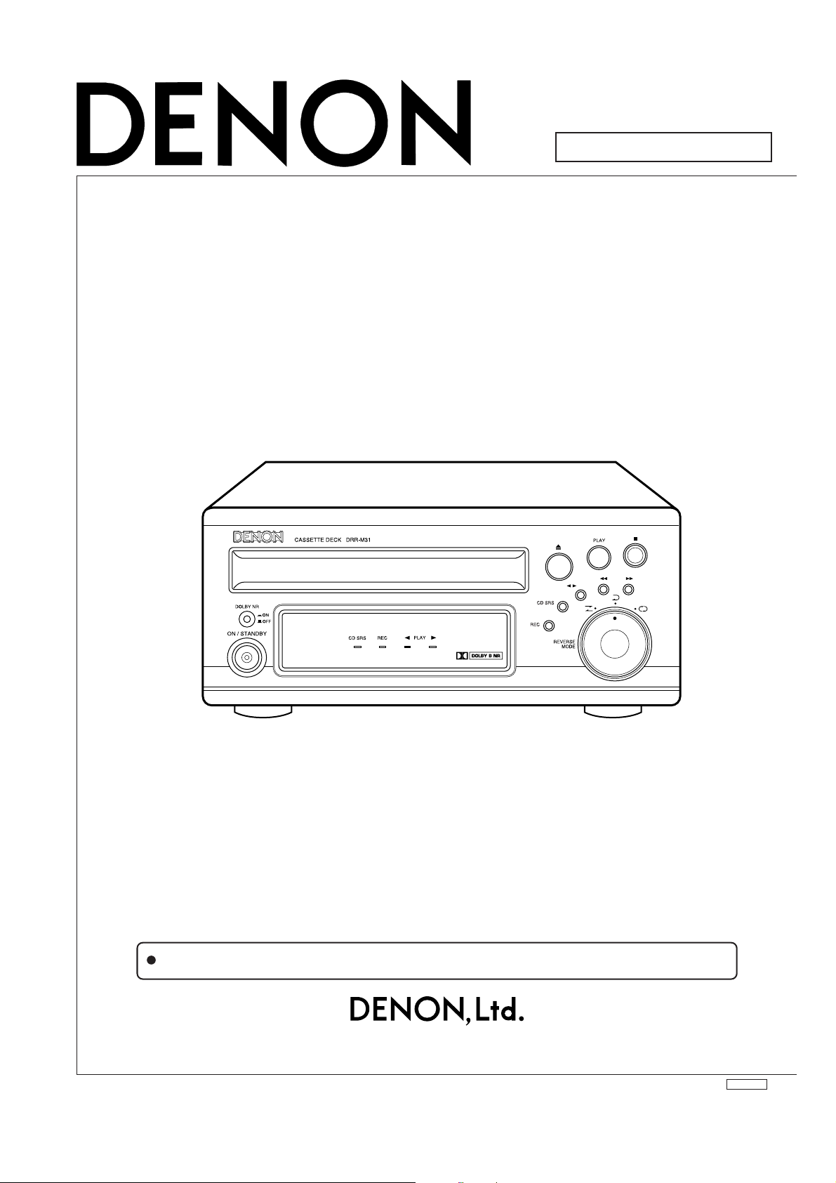
For Europe model
SERVICE MANUAL
MODEL
STEREO CASSETTE DECK
DRR-M31
Some illustrations using in this service manual are slightly different from the actual set.
16-11, YUSHIMA 3-CHOME, BUNKYOU-KU, TOKYO 113-0034 JAPAN
Telephone: 03 (3837) 5321
X0166V.02 DE/CDM 0302

SAFETY PRECAUTIONS
The following check should be performed for the continued protection of the customer and service technician.
LEAKAGE CURRENT CHECK
Before returning the unit to the customer, make sure you make either (1) a leakage current check or (2) a line to chassis
resistance check. If the leakage current exceeds 0.5 milliamps, or if the resistance from chassis to either side of the
power cord is less than 460 kohms, the unit is defective.
2DRR-M31
2
DISASSEMBLY
(Follow the procedure below in reverse order when reassembling)
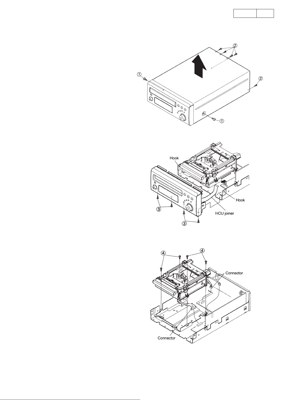
1. TOP COVER
(1) Remove 2 screws ① fixing from the both
sides.
(2) Remove 5 screws ② fixing to the Rear Plate,
then detach the Top Cover in the arrow direction .
2. FRONT PANEL
(1) Disconnect 1 HCU joiner coming from the
front P.W.B.
(2) Remove 4 screws ③ fixing the Front Panel at
the bottom.
(3) Whil releasing 2 hooks, detach the Front
Panel.
3DRR-M31
3. CASSETTE MECHA. ASS’Y
(1) Remove 4 screws ④ fixing the Cassette
Mecha. Ass’y.
(2) Disconnect 3 connectors, then detach the
Cassette Mecha. Ass’y.
3
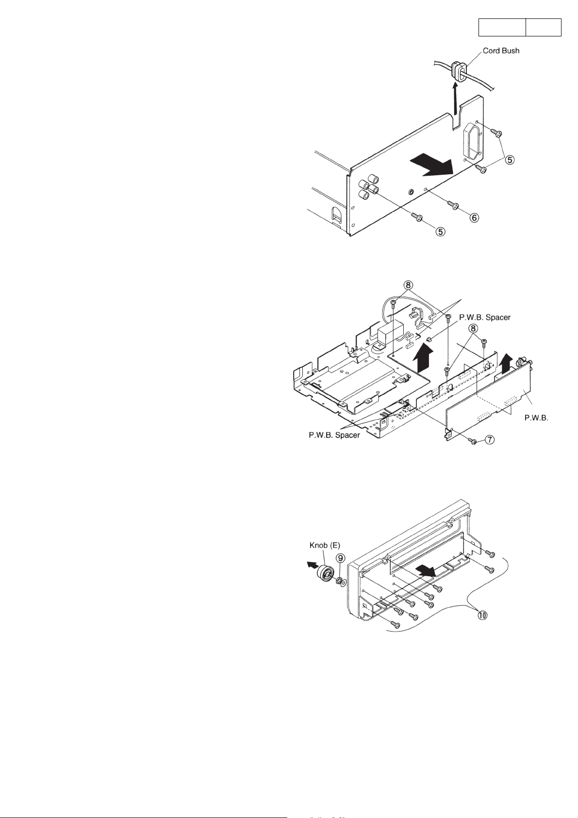
4. REAR PLATE
(1) Pull up the Power Cord together with the cord
bush to disengage from the Rear Plate.
(2) Remove 3 screws ⑤ fixing the 4P pin jack and
AC outlet respectively.
(3) Remove 1 screw ⑥ , and detach the Rear Plate.
5. MAIN P.W.B.
(1) Remove 1 screw ⑦ fixing the AMP P.W.B.
(2) Pull up the AMP P.W.B. as shown in the arrow
direction, and disconnect 2 connectors.
(3) Remove 4 screws ⑧ fixing the Main P.W.B.
(4) Release 3 pieces of P.W.B. spacers.
(5) Disconnect the connector from the Trans Unit.
(6) Take off the Main P.W.B.
4DRR-M31
Connector
6. DISPLAY P.W.B.
(1) Pull out the knob (E).
(2) Remove the nut and washer ⑨ for the rotary
switch.
(3) Remove 9 screws ⑩ .
(4) Take off the Display P.W.B.
AMP
4
ADJUSTMENTS
6
ADJUSTMENTS
Adjusting and Checking the Mechanism Section
5DRR-M31
1. Replacement of the pinch roller
Before replacing the pinch roller, clean the tape contact
surface of the pinch roller and the tape contact surface of
the capstan shaft. After replacement, run a C-90 tape
without a pad and check for the presence of tape curl at
the tape guide portion of the head.
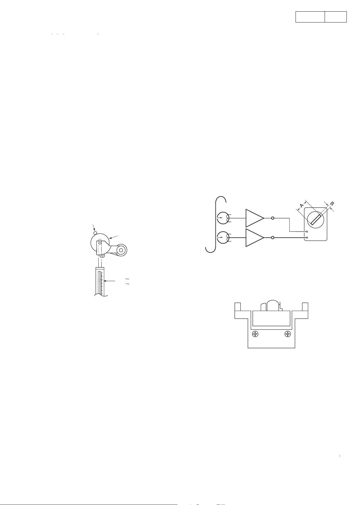
2. Checking the pinch roller pressure
Set to the playback condition and hook a bar-type spring
scale to the bracket above the center line of the pinch
roller. Pull the pinch roller away from the capstan shaft,
then allow the pinch roller to come into contact with the
capstan shaft and check that the reading of the bar-type
spring scale is between 2.45 N~3.92 N (250~400 g) when
the pinch roller starts to rotate or pull force indicates more
than 7.85 mN (80 g).
Replace the pinch roller when the value falls outside of
the specified range.
Capstan shaft
Pinch roller
4. Adjustment of the recording/playback head
Azimuth adjustment
Load side A of the A-BEX TCC-153 test tape facing
forward, and adjust.
(1) Play in the FWD direction and turn the azimuth
adjustment nut for the FWD side so that the
Lissajous’s figure becomes maximum at (A) and
minimum at (B).
(2) Play in the REV direction and turn the azimuth
adjustment nut for the REV side as adjusting the
FWD side method.
(3) Adjust (1) and (2) again.
(4) Apply screw lock to the adjustment locations.
PB Amp
LINE OUT
L
V
R
H
2.45 3.92N
(250
400g)
3. Replacement of the recording/playback
assembly
3-1 Removal of the head assembly
(1) Remove the 2 BRACKET-HEAD fastening screws.
(2) Remove one screw fixing P.W.B.
3-2 Mounting the recording/playback head assembly
Perform by following the steps of Section 3-1
Removal of the head assembly in reverse.
head
A-BEX TCC-153
REC/PB HEAD
A
FWD SIDE
B
REV SIDE
5. Checking the winding torque
Load a cassette type torque meter (Sony TW2111A at
the FWD side) and check that the reading of the torque
meter during playback is
294 to 686 mN-cm (30 to 70 g-cm) at the center value.
5
6. Checking the back tension torque at the time
r
of recording and playback
Load a cassette type torque meter (Sony TW2111A at
the FWD side, Sony TW2121A at the REV side) and check
that the reading of the torque meter during playback is
9.8~58.5 mN-cm (1~6 g-cm) and that there is no
unevenness.
7. Checking the FF and REW torque
Load a cassette type torque meter (Sony TW2231) and
check that the value indicated by the torque meter for
winding and rewinding is between 686 mN-cm~
(70~150 g-cm).
1.47 N-cm
Adjusting and Checking the Electrical Section
6DRR-M31
8. Checking the FF and REW time
Load a Type 1 tape (UD-1), and check that the time for
FF and REW is less than 120 seconds. When outside of
the specified range, check Steps 5 and 6.
9. Checking the erroneous erasure prevention,
and the metal and chrome switch operations
Check that detection lever is operating the switch properly
depending upon the presence or absence of a hole.
Measuring instruments needed for the adjustments
(1) Low frequency oscillator
(2) Variable resistance attenuator
(3) Electronic voltmeter
(4) Oscilloscope
(5) Frequency counter
(6) Adjustment screwdriver
(7) Test tapes
MTT-111, MTT-114N, MTT-150, Type1 tape (UD-1)
(8) Mirror cassette for the transport (A-BEX TCC-902)
Adjustment precaution
(1) Before adjustments, use gauze or a swab moistened
with alcohol to wipe the surface of the heads, the
capstan shaft, and the pinch roller.
(2) Demagnetize the record/playback head and the
erase head with a head eraser.
(3) Completely demagnetize the driver to be used for
the adjustments.
(4) Unless otherwise specified, set the various operation
controls as indicated below.
Dolby NR switch: Off
1. Tape transport check
Load the mirror cassette for the transport, and illuminate
the area around the fixed guide of the record/playback
head with a lamp and observe.
Check that the tape edge is not hitting the tape guide
portion.
Note that the tape transport is the greatest factor affecting
the performance of the cassette deck. Never move the
inspection locations without good reason.
For information about replacement and adjustment of the
record/playback head, see the section “Adjustment and
checking of the mechanism”.
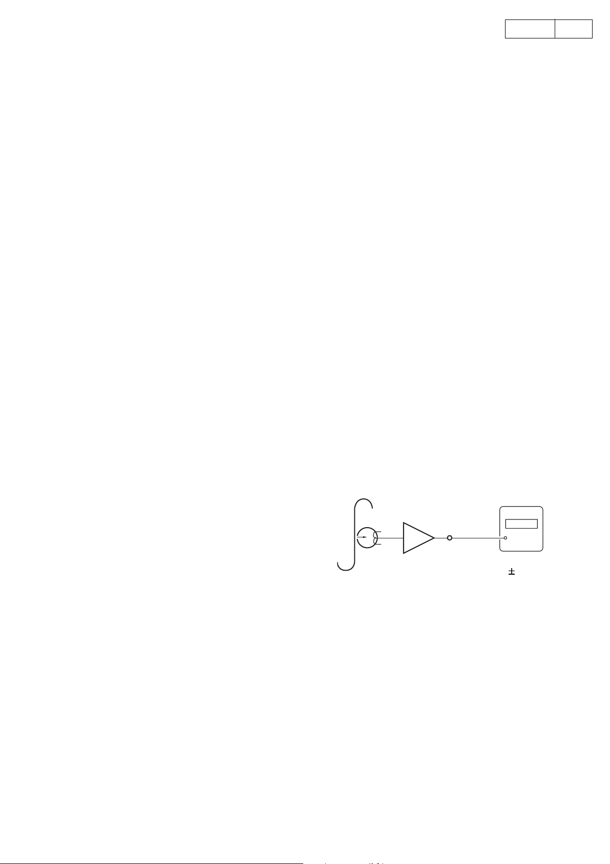
2. Tape speed check and adjustment
(1) Connect the frequency counter to the LINE OUT pin
and load the test tape (MTT-111).
(2) Playback FWD side of the test tape. At about halfway
through the tape, where the tape transport is stable,
confirm that the frequency counter will have a
reading within the range of 3,000 Hz ±10 Hz.
(3) Check REV side also that the counter reading
indicates within 2955~3045Hz.
Note: Adjust within 30 seconds, after pre-heating
(Play) of 20min, or more.
Frequency counte
PB Amp
LINE OUT
MTT-111
3000
3000Hz
10Hz
6
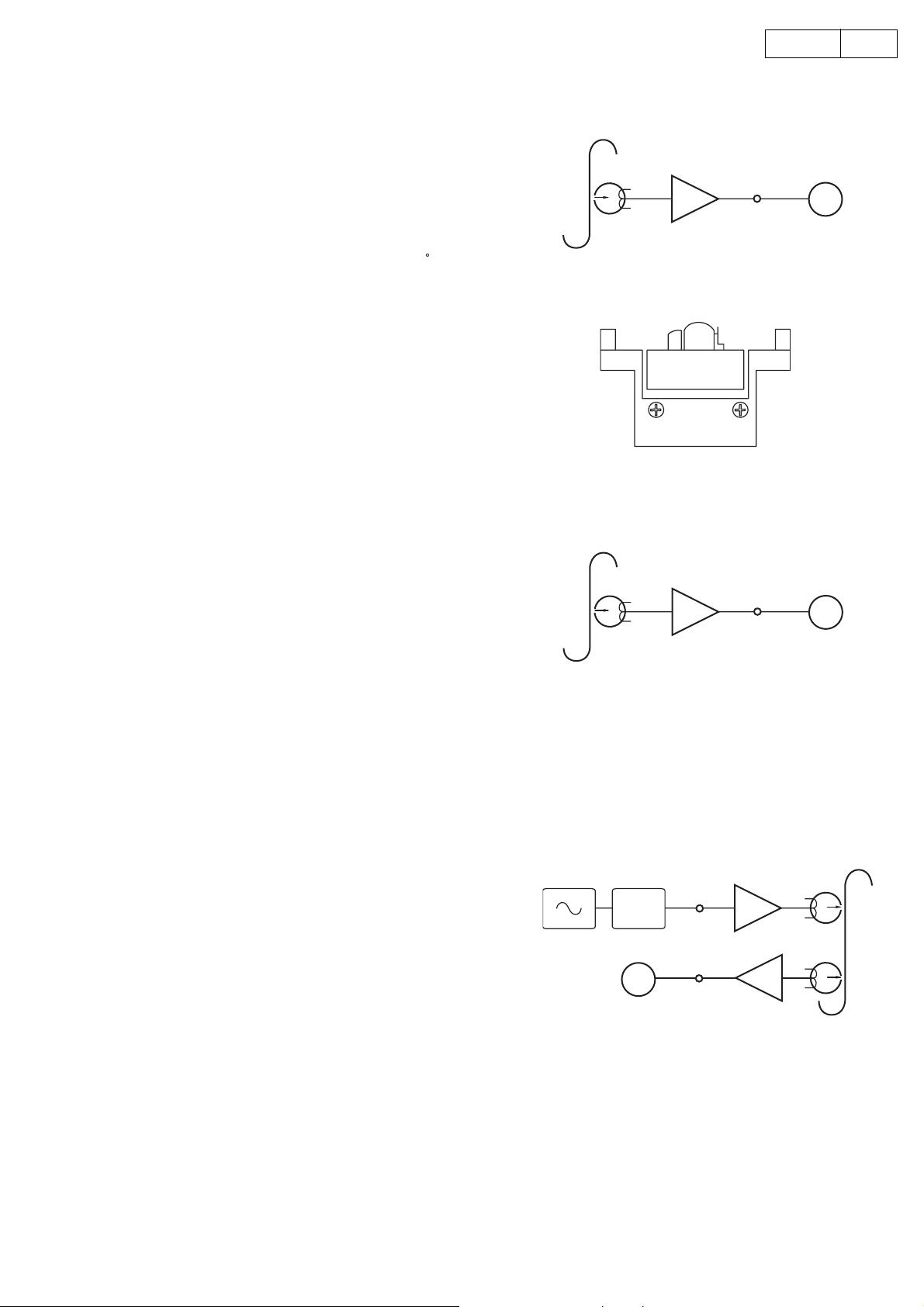
3. Azimuth Adjustment
)
(1) Connect an electronic voltmeter to the Line Out
terminal, and set Test tape MTT-114N into the Unit.
(2) Playback FWD side,and adjust the azimuth screw A
so as to get maximum indication on the voltmeter,
then make the same adjustment with the screw B for
REV side.
(3) Readjust if the output level difference exceeds 2dB
after adjustment, and also confirm that the phase
difference in the both channels is within ±45
Note: In order to prevent the backlash of the azimuth
screw, end in the clockwise rotation.
7DRR-M31
PB Amp
LINE OUT
.
MTT-114N
V. V
4. PB Output Level Adjustment
(1) Connect an electronic voltmeter to the Line Out
terminal, and set Test tape MTT-150 into the Unit.
(2) Playback FWD side, and adjust the VR301 (Lch) and
VR302 (Rch) so that the voltmeter indicates 400mV
±0.5dB.
5. REC Level Adjustment
(1) Set Test Tape (Type1 tape: UD-1) into the Unit,and
record 400mV −10dB 400Hz signal at JK301 input
level on the tape.
(2) Playback the recorded signal, and adjust VR304 (Lch)
and VR303 (Rch) so that the voltmeter indicates
−10dB ±0.5dB at JK301 output level.
MTT-150
400Hz
A
FWD SIDE
ATT
V. V
B
REV SIDE
PB Amp
LINE OUT
V. V
REC Amp
LINE IN
LINE OUT
PB Amp
Type 1 tape(UD-1
7
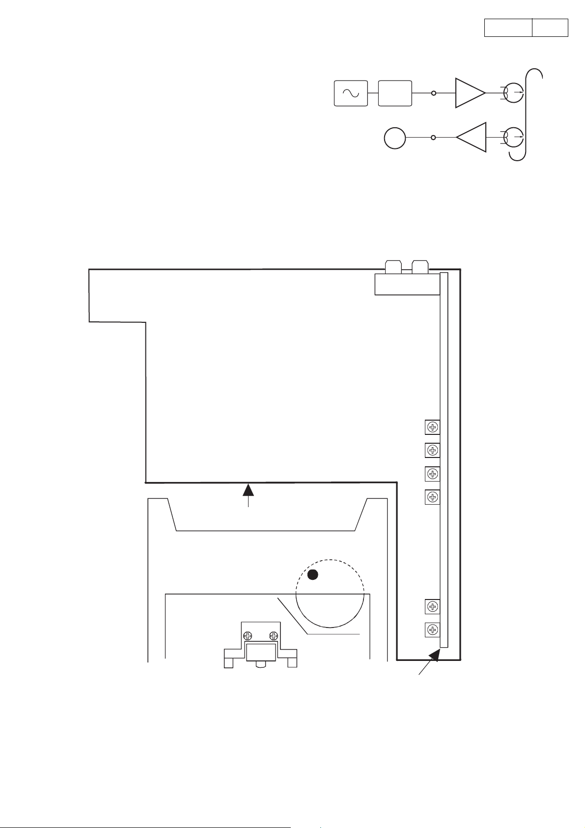
6. Bias Current Adjustment
)
(1) Set Test Tape (Type1 tape: UD-1) into the Unit, and
record 400mV -23dB 1.25kHz/12.5kHz signal at JK301
level on the tape.
(2) Playback the recorded signal, and adjust VR306 (Lch)
and VR305 (Rch) so that the level difference between
both frequencies becomes within the range of
+2dB ~ -0.5dB on the voltmeter.
ADJUSTMENT POINTS
ATT
1.25kHz
12.5kHz
V. V
LINE IN LINE OUT
JK301
8DRR-M31
REC Amp
LINE IN
LINE OUT
PB Amp
Type 1 tape(UD-1
(Deck Mecha.)
MAIN P.W.B
Azimuth Adjust
R/P Level Adjust
PB GAIN Adjust
Tape Speed Adjust
Rch
VR304
Lch
VR303
Lch
VR301
Rch
VR302
Lch
VR306
Rch
VR305
AMP P.W.B
8
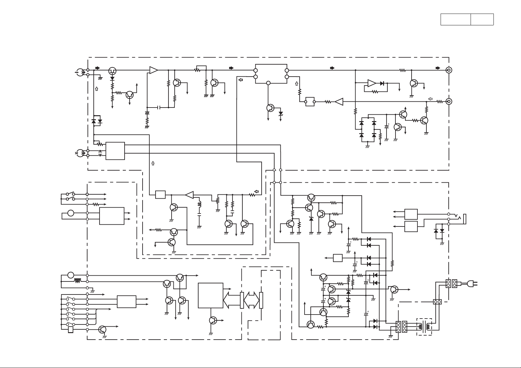
BLOCK DIAGRAM
DRR-M31
9
CLOSE
OPEN
LOADING
MOTOR
CAPSTAN
MOTOR
SOL
R/P HEAD
E. HEAD
HALL IC
M
M
CrO2 SW
NOR SW
F. REC
R. REC
HALF
MODE
TU201,202
BIAS ADJ.
VR201,202
μCOM. CLOSE
μCOM. OPEN
+5V
IC302
MOTOR
DRIVE
+5V
μCOM
R/P
SWITCHING
-7V
L203
TR204
TR205
BIAS OSC
μCOM
TR506
TR507
μCOM. REEL PULSE
μCOM
R/P
+B
-7V
+7V
TR203
PLAYBACK
AMP
IC201
BIAS TRAP
+5V
μCOM
R. MUTE
TR501
NOR
CrO
2
TR307
TR308
SOLENOID
μCOM
PLAY BACK LEVEL ADJ.
VR203,204
TR206,207
NOR
REC AMP REC LEVEL ADJ.
IC301
TR303
TR304
TR502
TR504 TR505
MOTOR
μCOM
+12V
RESET
VR301
VR302
IC501
μCOM
TR208,209
μCOM
R/P
TR510
TR305,306
NOR
+5V
P. OFF
PB IN
REC OUT
TR301,302
IC203
DOLBY IC
TR201
-7V
KEY
& LED
DISTLAY PWB
PB OUT ( Lch )
REC IN
D.RP
TR509 ( μCOM )
TR312
2
CrO
R/P PWB
TR313
-7V
TR328
MPX
FILTER
L201,202
TR314
+7V
TR327
TR315
+5V
TR326
TR324
IC205
TR316
μCOM
BIAS
IC304
TR325
IC204
LEVEL DETECT AMP ( A/D )
AUTO LEVEL CONTROL
P. OFF
+12V
DOLBY IC
PB OUT ( Rch )
MAIN PWB
μCOM. SO
μCOM. SI
μCOM. SCK
μCOM
A/D INPUT
TR211
μCOM
R. MUTE
TR323
TP215,216
TR317
( LINE MUTE OUT )
+7V
TR212
P. ON
LD405
(
Green
T101
POWER TRANS
LINE OUT
LINE MUTE
LINE IN
TR213,214
CD SYNCHRO
JK301
AC PLUG
(
9
SEMICONDUCTORS
IC's
µ µ
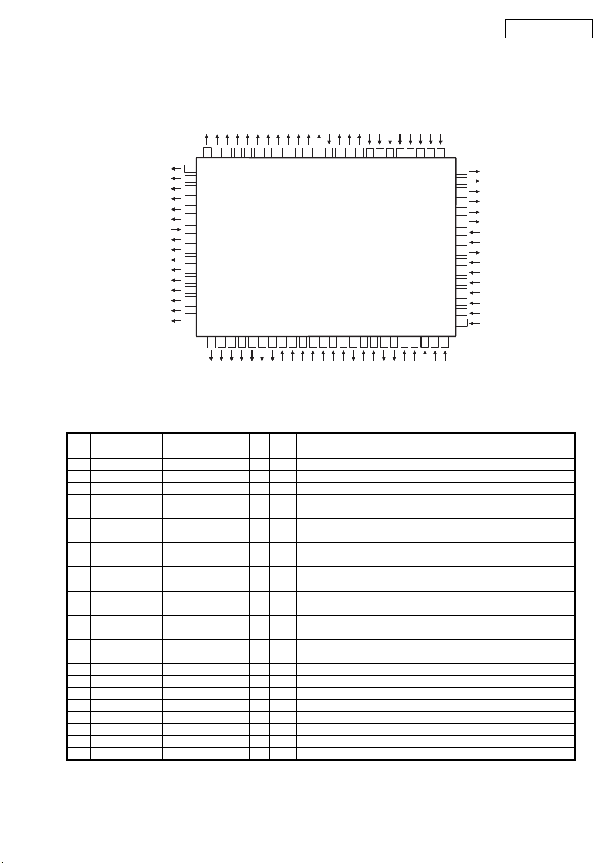
µPD78044FGF (IC203)
µ µ
P113 / FIP21
P112 / FIP20
P111 / FIP19
P110 / FIP18
P107 / FIP17
P106 / FIP16
VLOAD
P105 / FIP15
P104 / FIP14
P103 / FIP13
P102 / FIP12
P101 / FIP11
P100 / FIP10
P97 / FIP9
P96 / FIP8
P95 / FIP7
10DRR-M31
P114 / FIP22
P115 / FIP23
P116 / FIP24
P117 / FIP25
P120 / FIP26
P121 / FIP27
P122 / FIP28
P123 / FIP29
P124 / FIP30
P125 / FIP31
P126 / FIP32
P127 / FIP33
VDD
P70
P71
P72
IC (VPP)
P00 / INTP0
P01 / INTP1
P02 / INTP2
P03 / INTP3
P30 / TO0
P31 / TO1
P32 / TO2
6061
62
64
63
65
66
67
68
69
70
71
72
73
74
75
76
77
78
79
80
57
59
58
55
56
54
53
5152
TOP VIEW
46
4748
49
50
41
42
P33 / TI1
40
39
P34 / TI2
P35 / PCL
38
P36 / BUZ
37
36
P37
X2
35
X1
34
VSS
33
32
XT2
31
P04 / XT1
30
AVREF
29
AVDD
28
P10 / ANI0
27
P11 / ANI1
26
P12 / ANI2
25
P13 / ANI3
43
45
44
3
2
P94 / FIP6
P93 / FIP5
P92 / FIP4
4567
P91 / FIP3
P90 / FIP2
P81 / FIP1
P80 / FIP0
1
11
9
8
10
VDD
P26 / SO0
P27 / SCK0
P25 / SI0
12 13
P24 / BUSY
14
P23 / STB
P22 / SCK1
15 16
P21 / SO1
17 18 19 20
P74
RESET
P20 / SI1
P73
21
AVSS
22
23 24
P17 / ANI7
P16 / ANI6
P15 / ANI5
P14 / ANI4
PPPPPD78044FGF Terminal Function
Pin
No.
10 P26/SO0
11 P26/SI0 REC REV I Hi-z Deck mecha REC REV SW input
12 P24/BUSY PACK I Hi-z Deck mecha PACK SW input
13 P23/STB
14 P22/SCK1 SERCLK I Hi-z DENON BUS communication clock signal (Edge intervention)
15 P21/SO1 SEROUT O Hi-z DENON BUS communication output data signal
16 P20/SI1 SER IN I Hi-z DENON BUS communication input data signal
17 RESET RESET I Hi-z Reset input
18 P74 R MUTE
19 P73 HEADSW O Hi-z Head switching control signal (L: PB only)
20 AVSS AVSS O
21 P17/AN17 RVSMOD I Hi-z Reverse mode input signal
22 P16/AN16 KEYIN 2 I Hi-z Tact operating button input No.2
23 P15/AN15 KEYIN 1 I Hi-z Tact operating button input No.1
24 P14/AN14 KEYIN 1 I Hi-z Tact operating button input No.0
25 AN13 MSREF I Hi-z Music serch detection reference voltage
Port Name Symbol I/O Ini Function
1 P94/FIP6 MTCONT2 O Hi-z Reel, Loader motor control
2 P93/FIP5 MTCONT1 O Hi-z Reel, Loader motor control
3 P92/FIP4 LED FP O Hi-z LED output FWD, PLAY ind. (H: light )
4 P91/FIP3 LED RP O Hi-z LED output REV, PLAY ind. (H: light )
5 P90/FIP2 LED REC O Hi-z LED output REC ind. (H: light )
6 P81/FIP1 LED SRS O Hi-z LED output CD SRS ind. (H: light )
7 P80/FIP0 LED PWR O Hi-z LED output POWER. (H: light )
8VDD VDD
+5V Power
9 P27/SCK0 REC FWD I Hi-z Deck mecha REC FWD SW input
I Hi-z Not used (connect to GND)
I Hi-z Not used (connect to GND)
Hi-z REC mute control signal (H: mute)
Analog GND
10
Loading...