


STEREO RECEIVER
DRA-F101
OPERATING INSTRUCTIONS
MODE D’EMPLOI
INSTRUCCIONES DE OPERACION
OFF ON
SYSTEM
POWER
|
|
|
|
|
|
|
|
|
STOP |
PLAY VOLUME |
|
|
|
|
|
|
|
|
|
|
/SELECT |
|
|
|
|
|
|
|
|
VOLUME |
PRESET |
|
|
|
|
|
|
|
|
|
|
|
|
FUNCTION |
|
|
|
MEMORY |
TUNING |
|
|
SOURCE |
|
+ |
TONE |
TIMER |
DISPLAY |
/ SET |
DOWN |
UP |
BAND |
DIRECT |
|
|
|
|
|
|
|
|
|
|
|
|
- |
|
|
|
|
|
|
|
|
|
|
TAPE |
SLEEP FUNCTION MODE |
|
|
|
|
|
|
|
|
|
|
|
SYSTEM |
|
|
|
|
|
|
|
|
|
|
ON / STANDBY |
|
|
|
|
|
|
|
|
|
CD |
PHONES |
|
|
|
|
|
|
|
|
TUNER |
MD |
|
|
|
|
|
|
|
|
|
|
|
|
|
|
|
|
|
|
|
|
TAPE |
|
|
|
|
|
|
|
|
|
AM-FM STEREO RECEIVER DRA-F101 |
|
|
|
|
|
|
|
|
|
|
|
|
RC-927 |
|
|
|
|
|
|
|
|
|
REMOTE CONTROL UNIT |
|
FOR ENGLISH READERS |
PAGE |
004 |
~ PAGE |
019 |
POUR LES LECTEURS FRANCAIS |
PAGE |
020 |
~ PAGE |
035 |
PARA LECTORES DE ESPAÑOL |
PAGINA 036 |
~ PAGINA 051 |
||
IMPORTANT TO SAFETY
WARNING:
TO PREVENT FIRE OR SHOCK HAZARD, DO NOT EXPOSE THIS APPLIANCE TO RAIN OR MOISTURE.
CAUTION
1.Handle the power supply cord carefully
Do not damage or deform the power supply cord. If it is damaged or deformed, it may cause electric shock or malfunction when used. When removing from wall outlet, be sure to remove by holding the plug attachment and not by pulling the cord.
2.Do not open the top cover
In order to prevent electric shock, do not open the top cover.
If problems occur, contact your DENON DEALER.
3.Do not place anything inside
Do not place metal objects or spill liquid inside the system.
Electric shock or malfunction may result.
Please, record and retain the Model name and serial number of your set shown on the rating label.
Model No. DRA-F101
Serial No.
CAUTION
RISK OF ELECTRIC SHOCK
DO NOT OPEN
CAUTION:
TO REDUCE THE RISK OF ELECTRIC SHOCK, DO NOT REMOVE COVER (OR BACK). NO USER-SERVICEABLE PARTS INSIDE. REFER SERVICING TO QUALIFIED SERVICE PERSONNEL.
The lightning flash with arrowhead symbol, within an equilateral triangle, is intended to alert the user to the presence of uninsulated “dangerous voltage” within the product’s enclosure that may be of sufficient magnitude to constitute a risk of electric shock to persons.
The exclamation point within an equilateral triangle is intended to alert the user to the presence of important operating and maintenance (servicing) instructions in the literature accompanying the appliance.
NOTE:
This stereo receiver uses the semiconductor laser. To allow you to enjoy music at a stable operation, it is recommended to use this in a room of 5°C (41°F) — 35°C (95°F).
This device complies with Part 15 of the FCC Rules. Operation is subject to the following two conditions: (1) This device may not cause harmful interference, and (2) this device must accept any interference received, including interference that may cause undesired operation.
This Class B digital apparatus meets all requirements of the Canadian InterferenceCausing Equipment Regulations.
Cet appareil numérique de la classe B respecte toutes les exigences du Règlement sur le matériel brouilleur du Canada.
• FOR CANADA MODEL ONLY
CAUTION
TO PREVENT ELECTRIC SHOCK, MATCH WIDE BLADE OF PLUG TO WIDE SLOT, FULLY INSERT.
•POUR LES MODELE CANADIENS UNIQUEMENT
ATTENTION
POUR ÉVITER LES CHOCS ÉLECTRIQUES, INTERODUIRE LA LAME LA PLUS LARGE DE LA FICHE DANS LA BORNE CORRESPONDANTE DE LA PRISE ET POUSSER JUSQU’ AU FOND.
SAFETY INSTRUCTIONS
1.Read Instructions – All the safety and operating instructions should be read before the product is operated.
2.Retain Instructions – The safety and operating instructions should be retained for future reference.
3.Heed Warnings – All warnings on the product and in the operating instructions should be adhered to.
4.Follow Instructions – All operating and use instructions should be followed.
5.Cleaning – Unplug this product from the wall outlet before cleaning. Do not use liquid cleaners or aerosol cleaners.
6.Attachments – Do not use attachments not recommended by the product manufacturer as they may cause hazards.
7.Water and Moisture – Do not use this product near water
– for example, near a bath tub, wash bowl, kitchen sink, or laundry tub; in a wet basement; or near a swimming pool; and the like.
8.Accessories – Do not place this product on an unstable cart, stand, tripod, bracket, or table. The product may fall, causing serious injury to a child or adult, and serious damage to the product. Use only with a cart, stand, tripod, bracket, or table recommended by the manufacturer, or sold with the product. Any mounting of the product should follow the manufacturer’s instructions, and should use a mounting accessory recommended by the
manufacturer.
9. A product and cart combination should be moved with care. Quick stops, excessive force, and uneven surfaces may cause the product and cart combination to overturn.
10.Ventilation – Slots and openings in the cabinet are provided for ventilation and to ensure reliable operation of the product and to protect it from overheating, and these openings must not be blocked or covered. The openings should never be blocked by placing the product on a bed, sofa, rug, or other similar surface. This product should not be placed in a built-in installation such as a bookcase or rack unless proper ventilation is provided or the manufacturer’s instructions have been adhered to.
11.Power Sources – This product should be operated only from the type of power source indicated on the marking label. If you are not sure of the type of power supply to your home, consult your product dealer or local power company. For products intended to operate from battery power, or other sources, refer to the operating instructions.
12.Grounding or Polarization – This product may be equipped with a polarized alternating-current line plug (a plug having one blade wider than the other). This plug will fit into the power outlet only one way. This is a safety feature. If you are unable to insert the plug fully into the outlet, try reversing the plug. If the plug should still fail to fit, contact your electrician to replace your obsolete outlet. Do not defeat the safety purpose of the polarized plug.
FIGURE A
EXAMPLE OF ANTENNA GROUNDING
AS PER NATIONAL
ELECTRICAL CODE ANTENNA
LEAD IN
WIRE
GROUND
CLAMP
ANTENNA DISCHARGE UNIT (NEC SECTION 810-20)
ELECTRIC
SERVICE
EQUIPMENT
GROUNDING CONDUCTORS (NEC SECTION 810-21)
GROUND CLAMPS
POWER SERVICE GROUNDING ELECTRODE SYSTEM
(NEC ART 250, PART H)
NEC - NATIONAL ELECTRICAL CODE
13.Power-Cord Protection – Power-supply cords should be routed so that they are not likely to be walked on or pinched by items placed upon or against them, paying particular attention to cords at plugs, convenience receptacles, and the point where they exit from the product.
15.Outdoor Antenna Grounding – If an outside antenna or cable system is connected to the product, be sure the antenna or cable system is grounded so as to provide some protection against voltage surges and built-up static charges. Article 810 of the National Electrical Code, ANSI/NFPA 70, provides information with regard to proper grounding of the mast and supporting structure, grounding of the lead-in wire to an antenna discharge unit, size of grounding conductors, location of antenna-discharge unit, connection to grounding electrodes, and requirements for the grounding electrode. See Figure A.
16.Lightning – For added protection for this product during a lightning storm, or when it is left unattended and unused for long periods of time, unplug it from the wall outlet and disconnect the antenna or cable system. This will prevent damage to the product due to lightning and power-line surges.
17.Power Lines – An outside antenna system should not be located in the vicinity of overhead power lines or other electric light or power circuits, or where it can fall into such power lines or circuits. When installing an outside antenna system, extreme care should be taken to keep from touching such power lines or circuits as contact with them might be fatal.
18.Overloading – Do not overload wall outlets, extension cords, or integral convenience receptacles as this can result in a risk of fire or electric shock.
19.Object and Liquid Entry – Never push objects of any kind into this product through openings as they may touch dangerous voltage points or short-out parts that could result in a fire or electric shock. Never spill liquid of any kind on the product.
20.Servicing – Do not attempt to service this product yourself as opening or removing covers may expose you to dangerous voltage or other hazards. Refer all servicing to qualified service personnel.
21.Damage Requiring Service – Unplug this product from the wall outlet and refer servicing to qualified service personnel under the following conditions:
a)When the power-supply cord or plug is damaged,
b)If liquid has been spilled, or objects have fallen into the product,
c)If the product has been exposed to rain or water,
d)If the product does not operate normally by following the operating instructions. Adjust only those controls that are covered by the operating instructions as an improper adjustment of other controls may result in damage and will often require extensive work by a qualified technician to restore the product to its normal operation,
e)If the product has been dropped or damaged in any way, and
f)When the product exhibits a distinct change in performance – this indicates a need for service.
22.Replacement Parts – When replacement parts are required, be sure the service technician has used replacement parts specified by the manufacturer or have the same characteristics as the original part. Unauthorized substitutions may result in fire, electric shock, or other hazards.
23.Safety Check – Upon completion of any service or repairs to this product, ask the service technician to perform safety checks to determine that the product is in proper operating condition.
24.Wall or Ceiling Mounting – The product should be mounted to a wall or ceiling only as recommended by the manufacturer.
25.Heat – The product should be situated away from heat
sources such as radiators, heat registers, stoves, or other |
2 |
products (including amplifiers) that produce heat. |
ENGLISH FRANCAIS ESPAÑOL
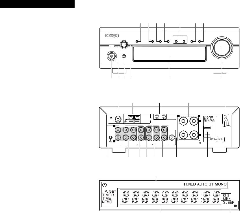
FRONT PANEL PANNEAU AVANT PANEL FRONTAL
REAR PANEL PANNEAU ARRIERE PANEL TRASERO
|
!3!2!1!0 |
o |
|
i u |
||||
|
|
|
|
|
|
|
|
VOLUME |
FUNCTION |
|
|
|
MEMORY |
TUNING |
|
|
SOURCE |
TONE |
TIMER |
DISPLAY |
/ SET |
DOWN |
UP |
BAND |
DIRECT |
|
SYSTEM |
|
|
|
|
|
|
|
|
ON / STANDBY |
|
|
|
|
|
|
|
|
PHONES |
|
|
|
|
|
|
|
|
|
|
|
|
|
|
|
|
AM-FM STEREO RECEIVER DRA-F101 |
q w e r |
|
|
t |
|
|
|
y |
|
@4 |
@3 |
|
@2 |
|
|
|
@1 |
@0 |
FM COAX. |
AM LOOP ANT. |
1 |
2 |
SYSTEM |
R |
L |
75 |
ANTENNA |
|
|
CONNECTOR |
|
+ |
|
|
|
|
|
||
|
|
|
|
|
|
L |
INPUTS |
|
TAPE |
|
MD |
|
|
|
|
|
|
|
|
PRE |
|
|
|
|
|
|
|
OUT |
|
|
|
|
|
|
|
|
- |
R |
|
|
|
|
|
SUB |
SPEAKER SYSTEM |
PHONO |
CD DVD/AUX |
PB |
REC |
PB |
SPEAKER IMPEDANCE 4~16 |
||
|
REC WOOFER |
|
|||||
!4 |
!5 !6!7!6!7 !8 |
!9 |
DISPLAY AFFICHAGE VISUALIZADOR
@5 |
|
@6 |
@5 |
3
ENGLISH FRANCAIS ESPAÑOL
NOTE ON USE / OBSERVATIONS RELATIVES A L’UTILISATION / NOTAS SOBRE EL USO
•Avoid high temperatures.
Allow for sufficient heat dispersion when installed on a rack.
•Eviter des températures élevées Tenir compte d’une dispersion de chaleur suffisante lors de l’installation sur une étagère.
•Evite altas temperaturas
Permite la suficiente dispersión del calor cuando está instalado en la consola.
•Keep the set free from moisture, water, and dust.
•Protéger l’appareil contre l’humidité, l’eau et la poussière.
•Mantenga el equipo libre de humedad, agua y polvo.
•Do not let foreign objects in the set.
•Ne pas laisser des objets étrangers dans l’appareil.
•No deje objetos extraños dentro del equipo.
•Handle the power cord carefully. Hold the plug when unplugging the cord.
•Manipuler le cordon d’alimentation avec précaution.
Tenir la prise lors du débranchement du cordon.
•Maneje el cordón de energía con cuidado.
Sostenga el enchufe cuando desconecte el cordón de energía.
•Unplug the power cord when not using the set for long periods of time.
•Débrancher le cordon d’alimentation lorsque l’appareil n’est pas utilisé pendant de longues périodes.
•Desconecte el cordón de energía cuando no utilice el equipo por mucho tiempo.
*(For sets with ventilation holes)
•Do not obstruct the ventilation holes.
•Ne pas obstruer les trous d’aération.
•No obstruya los orificios de ventilación.
•Do not let insecticides, benzene, and thinner come in contact with the set.
•Ne pas mettre en contact des insecticides, du benzène et un diluant avec l’appareil.
•No permita el contacto de insecticidas, gasolina y diluyentes con el equipo.
•Never disassemble or modify the set in any way.
•Ne jamais démonter ou modifier l’appareil d’une manière ou d’une autre.
•Nunca desarme o modifique el equipo de ninguna manera.
TABLE OF CONTENTS
z MAIN FEATURES ……………………………………… 4 x BEFORE USING ……………………………………… 5 c CONNECTING THE ANTENNAS …………………… 5 v CONNECTIONS …………………………………… 6, 7 b PART NAMES AND FUNCTIONS ………………… 8, 9 n SYSTEM REMOTE CONTROL ………………… 9~11
m OPERATION …………………………………… 12, 13
, LISTENING TO RADIO ………………………… 13, 14
. USING THE TIMER ……………………………… 15~17
⁄0SYSTEM FUNCTIONS ……………………………… 17
⁄1TROUBLESHOOTING ……………………………… 18
⁄2SPECIFICATIONS …………………………………… 19
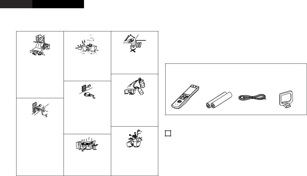
2 ACCESSORIES
Check that the following parts are included in the package aside from the main unit:
q Remote control unit (RC-927) …………………………1 |
r AM loop antenna |
……………………………………1 |
w Batteries R03 (AAA) ……………………………………2 |
t Operating instructions …………………………………1 |
|
e FM indoor antenna ……………………………………1 |
y Service station list |
……………………………………1 |
q |
w |
e |
r |
|
++ |
|
|
|
-- |
|
|
1 MAIN FEATURES
1. HC-TR output circuit for both subtlety and power |
4. Source Direct function for improved sound quality |
A single push-pull circuit using an HC-TR (high current transistor) based on the same principles as the UHCMOS used in the POA-S1, DENON’s top grade monaural power amplifier, achieves both stable a high current supply and excellent low level signal linearity. The result is an extremely high level of both subtlety and power.
2.Strong power circuitry supporting the expressive abilities of the HC-TR output circuit
The strong power circuitry consisting of high speed rectifier diodes and large high sound quality block condensers allow the HC transistor output circuit to be used to its maximum potential.
3.S.L.D.C.
The DRA-F101 uses an S.L.D.C. (Signal Level Divided Construction) with the ideal separation of the different circuits (low level signal circuit, high level signal circuit, microprocessor circuit, etc.)
The DRA-F101 is equipped with a source direct function that bypasses the bass, treble, loudness and balance control circuits to achieve a simple signal path, contributing to keeping the sound pure.
5.AM/FM tuner with random 40-station preset function
6.System remote control unit
The DRA-F101 comes with a system remote control unit that can be used to control the CD player (DCDF101) (when used system connections only).
7.Low standby power consumption
The power consumption when the power is in the standby mode is reduced to 1W or less.
4
2 BEFORE USING
Read the following before using the set.
•Before turning on the power
Check again that all connections are correct and that there are no problems with the connection cords. Be sure to unplug the power cord before connecting or disconnecting the connection cords.
•Moving the set
To prevent short-circuits or damage to the connection cords, always unplug the power cord and disconnect the connection cords between all other audio components when moving the set.
•Store this instructions in safe place
After reading, store this instructions along with the warranty in a safe place. Also fill in the items on the back paper for your convenience.
•Illustrations in this manual
Note that some of the illustrations used for explanations in this manual may differ from the actual set.
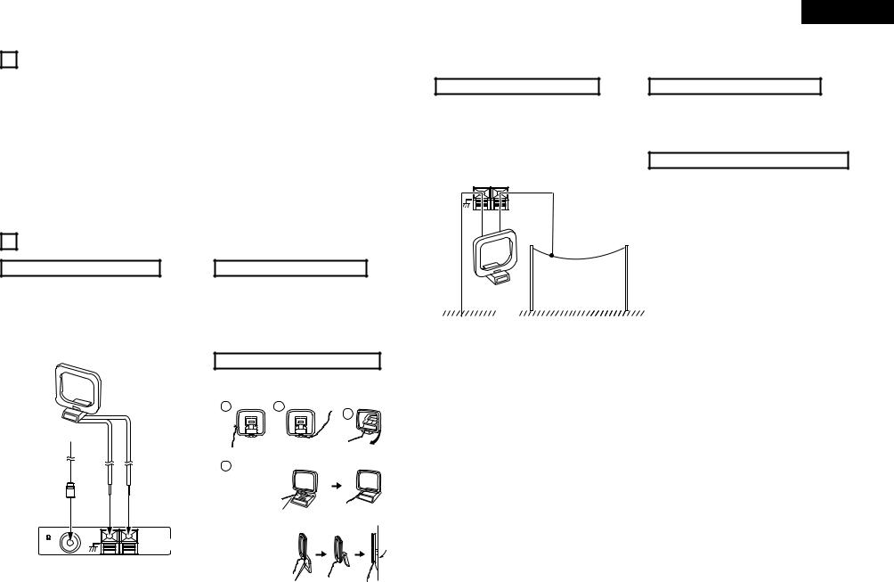
3 CONNECTING THE ANTENNAS
Installing the FM indoor antenna
Tune in FM station (see page 13), set the antenna so that distortion and noise is minimal, then secure the tip of the antenna in this position using tape or a pin.
AM loop antenna
FM antenna
FM COAX. |
AM LOOP ANT. |
75 |
ANTENNA |
|
Installing the AM loop antenna
Tune in an AM station (see page 13) and set the antenna as far from the system as possible to keep distortion and noise is minimal. In some cases, it is best to invert the polarities. AM broadcasts cannot be received well if the loop antenna is not connected or if it is set close to metal objects.
Assembling the AM loop antenna
1 2
Remove the vinyl tie and take out the
connection line.
4
a.With the antenna on top any stable
surface.
Mount
b.With the antenna attached to a wall.
Connect to the AM antenna terminals.
3
Bend in the reverse direction.
Installation hole Mount on wall, etc.
ENGLISH
Installing an AM outdoor antenna
Connect the signal wire from the AM outdoor antenna to
the antenna terminal. Be sure to connect the signal
ground wire to the  terminal. Also be sure to connect the included AM loop antenna.
AM LOOP ANT. |
ANTENNA |
Connecting an FM outdoor antenna
If good reception cannot be achieved with the included FM antenna, use an FM outdoor antenna. Connect an IECtype connector to the coaxial cable and connect the antenna to the FM COAX (75 Ω/ohms) terminal.
Selecting a place for the FM outdoor antenna
•Set the antenna so that it points towards the broadcast station’s transmitting antenna. Behind buildings or mountains, set the antenna in the position at which reception is best, and also try changing the direction of the antenna.
•Do not install the antenna under power lines.
Doing so is extremely dangerous, as the power line could touch the antenna.
•Install the antenna away from roads or train tracks to avoid noise from cars or trains.
•Do not install the antenna too high, as it may be hit by lightning.
|
|
AM loop antenna |
AM outdoor antenna |
|
Note to CATV system installer: |
||
|
|
|
|
|
|
|
This reminder is provided to call the CATV system |
|
|
|
|
|
|
||
|
|
|
|
|
|
|
installer’s attention to Article 820-40 of the NEC |
|
Signal ground |
|
|||||
|
|
|
which provides guidelines for proper grounding and, |
||||
|
|
|
|
|
|
|
in particular, specifies that the cable ground shall be |
|
|
|
|
|
|
|
connected to the grounding system of the building, |
|
|
|
|
|
|
|
as close to the point of cable entry as practical. |
|
|
|
|
|
|
|
|
5
ENGLISH
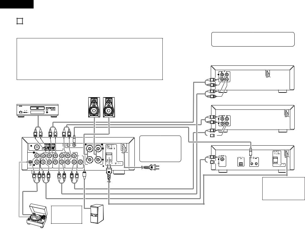
4 CONNECTIONS
2When connecting, also refer to the manuals of the other components.
2When connecting to the DCD-F101, make the system connection shown by dotted line on the diagram below.
2The DRA-F101 is not equipped with connection cord. Use the connection cord included with the DCD-F101.
NOTES:
•Do not plug the power cords into the power outlets until all connections have been completed.
•Check the left and right channels and be sure to interconnect them correctly (R to R, L to L).
•Plug in the power cords securely. Incomplete connections will result in noise.
•Use the AC OUTLET for audio equipment only. Do not use them for hair driers, etc.
•Do not clasp the connection cords together with the power cords or place them near other electric products. Doing so may result in noise.
•The PHONO input jack is extremely sensitive. A booming sound may be produced from the speakers if the volume is turned up when no turntable is connected.
•The sound of another component may be heard if no component is connected to the input jacks of the function selected with the FUNCTION selector.
Speaker system
DVD player
B
(L) |
(R) |
R |
L |
R |
L |
L |
R |
FM COAX. |
AM LOOP ANT. |
1 |
2 |
SYSTEM |
R |
L |
75 |
ANTENNA |
|
|
CONNECTOR |
|
+ |
|
|
|
|
|
||
|
|
|
|
|
|
L |
INPUTS |
|
TAPE |
|
|
MD |
PRE |
|
|
|
|
|
|
|
|
|
|
|
|
|
|
|
|
|
|
OUT |
|
|
|
|
|
|
|
|
- |
R |
|
|
|
|
|
|
|
SPEAKER SYSTEM |
|
CD |
DVD/AUX |
PB |
REC |
PB |
REC |
SUB SPEAKER IMPEDANCE 4~16 |
|
PHONO |
WOOFER |
|||||||
L |
R |
L |
R |
L |
R |
|
R |
L |
Subwoofer
NOTE:
• If noise is generated when the ground wire is connected, disconnect the ground wire.
•The D-F101 series stereo receiver (DRA-F101) is equipped with a clock and timer function, so be sure to connect it to a wall power outlet to which power is supplied constantly.
Power plug
AC 120V, 60 Hz
(Plug into a power outlet)
Turntable |
NOTE: |
(with MM cartridge) |
• This unit cannot be used with MC cartridges directly. Use a head |
|
amplifier or a step-up transformer with MC cartridges. |
|
|
•When making system connection with the DCD-F101, connect the system cord to the DRA-F101 system connector (either 1 or 2). (System connection is indicated by dotted line on the diagram.)
Cassette deck
L |
R |
L |
R |
MD recorder
L |
R |
L |
 R
R 
L |
 R
R 


CD player (DCD-F101)
NOTE:
• To allow for heat dispersal, do not place another component or any other object directly on top of the DRA-F101.
6
System Operations
•System operations such as the timer playback and auto power on functions can only be used if stereo audio cords and system cords are connected between all the system components. Be sure to securely connect all the connection cords between all the units.
•Disconnecting a system cord during system operation may result in malfunction. Be sure to unplug the power cords before changing the connections.
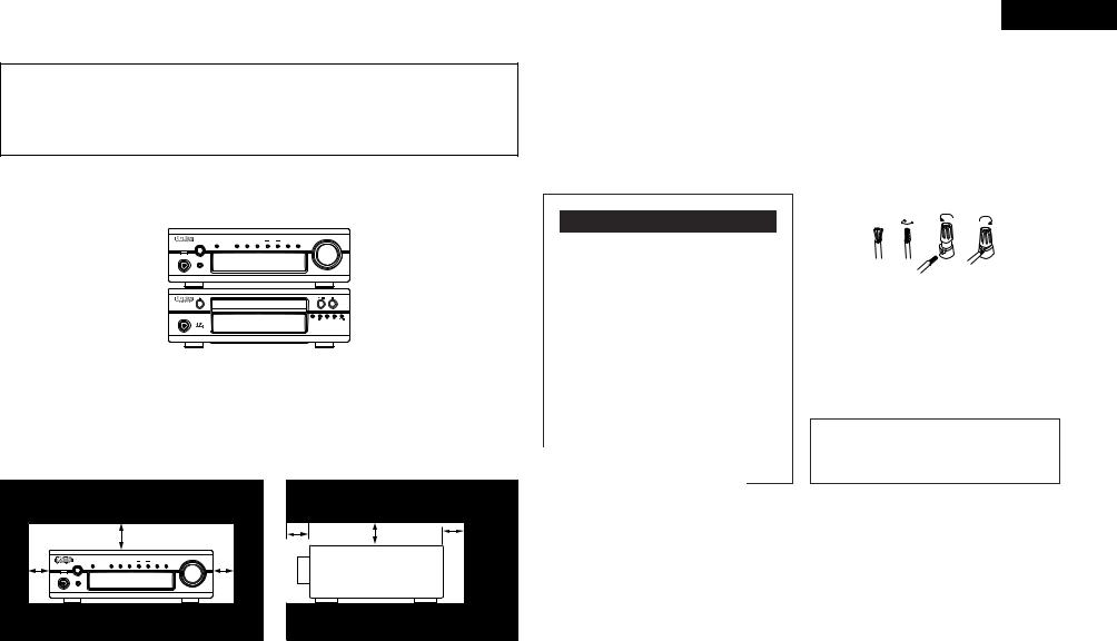
2Recommended System Installation
• To ensure performance and stability, install the system (D-F101 series) as shown below.
VOLUME
|
|
|
|
MEMORY |
TUNING |
|
|
SOURCE |
FUNCTION |
TONE |
TIMER |
DISPLAY |
/ SET |
DOWN |
UP |
BAND |
DIRECT |
(DRA-F101) |
ON / STANDBY |
|
SYSTEM |
|
PHONES |
AM-FM STEREO RECEIVER DRA-F101
(DCD-F101) |
ON / STANDBY |
|
REPEAT |
COMPACT DISC PLAYER DCD-F101
Do not place another component directly on top of the DRA-F101. To allow for heat dispersal, leave a space of at least 10 cm above the DRA-F101 so as not to obstruct its ventilation holes.
For stability, do not stack more than three components on top of each other.
For heat dispersal, leave at least 10 cm of space between the top, back and sides of this unit and the wall or other components.
|
|
10 cm or more |
|
|
|
5 cm |
|||
|
|
|||
|
|
|
|
|
|
|
VOLUME |
|
|
|
FUNCTION |
|
|
|
|
|
|
||
|
|
AM-FM STEREO RECEIVER DRA-F101 |
|
|
• Switching the input function when input jacks are |
Please be sure to unplug the cord when you leave |
not connected |
home for a vacation. |
A clicking noise may be produced if the input function is switched when nothing is connected to the input jacks. If this happens, either turn down the VOLUME control or connect components to the input jacks.
Connecting Speaker Systems
2 Speaker impedance
Use speaker systems with an impedance of 4 to 16Ω/ohms.
•Note that using speakers with other impedances will activate the protector circuit and may result in damage.
Protector Circuit
The DRA-F101 is equipped with a high speed protector circuit.
This circuit prevents strong currents from being generating inside the unit and damaging internal circuitry if the speaker cables are not securely connected to the speaker terminals or if they are short-circuited. If the protector circuit is activated, the speaker output is automatically cut off. If this happens, turn off the unit’s power, check the speaker cable connections, then turn the power back on. The sound will be muted for several seconds, after which the unit will operate normally.
ENGLISH
2 Connecting the speaker cords
q Peal off the coating from the tip of the cord. w Twist the core wire.
eTurn the speaker terminal counterclockwise to loosen it.
rCompletely insert the core wire, then turn the terminal clockwise to tighten it.
q w e r
BBe sure to connect the speaker cords to the terminals with the same polarities on the speaker and amplifier ( < to <, > to > ).
BWhen connecting, make sure that the speaker cords’ core wires do not stick out and touch other terminals, other core wires or the rear panel.
NOTE:
•NEVER touch the speaker terminals while the set is connected to a power supply. Doing so may result in electric shock.
7
ENGLISH
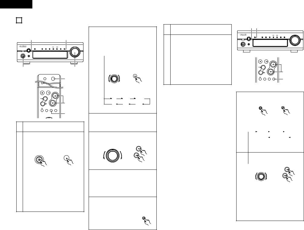
5 PART NAMES AND FUNCTIONS
(1) Front Panel
qPower operation switch (ON/STANDBY)
•This turns the power for the entire system on and off.
•Press this once to turn the power on, then press again to set the power to STANDBY mode.
•The LED color changes as follows, according to the condition:
During power ON : green
During STANDBY : red
During TIMER STANDBY: orange
The muting mode is set when the main unit’s power button is pressed and when the standby mode is canceled from the remote control unit. The power indicator flashes green when in the muting mode, then stops flashing and turns green once the set is in the operational mode.
If the indicator is flashing orange (quickly): The protective circuit is activated.
If this happens, unplug the power cord to turn the indicator off, then check the input and output terminals on the rear panel. Check in particular for short-circuiting of the speaker cords. Once all connections have been corrected, plug the power cord. (Wait for at least 10 seconds after turning
the power off before turning it back on.)
•When the DRA-F101 is connected in a system with the DCD-F101, its power button works as the
power button for the entire system. When the DRA-F101’s power turns on, the power of the DCD-F101 also turns on.
Power is supplied to the DRA-F101 even when the power is in the standby mode (low power consumption).
wREMOTE SENSOR (Remote Control Sensor)
•Point the included remote control unit (RC-927) at this sensor when operating it.
eHeadphones jack (PHONES)
•Use this jack to listen to the sound over commercially available headphones.
•When the headphones’ plug is inserted into the jack, the speaker output is automatically cut off, so no sound is produced from the speakers.
rFunction dial (FUNCTION)
•Switches the input function. Also used to set the modes selected with the mode button.
(See pages 12, 13.)
yVolume control dial (VOLUME)
•Use this to adjust the overall volume. (Rotary Encoder System).
•The volume increases when the control is turned clockwise (, ), decreases when it is turned counterclockwise (.).
•The volume increases and decreases in 63 steps from the minimum (VOLUME 0) to the maximum (VOLUME MAX).
uSource direct button (SOURCE DIRECT)
•When pressed and set to the “ON” position, the tone control (bass, treble, balance and loudness) circuits are set into default condition.
•When pressed again and set to the “OFF” position, the signals pass through the tone control circuits, so the tone (bass, treble, balance and loudness) can be adjusted as desired.
iBand button (BAND)
•Each time this button is pressed, the band and FM reception mode change as follows.
|
FM AUTO |
|
FM MONO |
|
AM |
|
|
|
|
|
|||
|
|
|
|
|
|
|
oTuning buttons
(TUNING UP AND DOWN)
•Use these buttons to tune in AM and FM stations. (TUNING UP/DOWN) (See page 13.)
!0Memory/set button (MEMORY/SET)
•Use this as the memory button when presetting AM and FM stations.
•Use this as the set button when setting the time and timer and when inputting data.
•When the PTY search mode, press this button to select the type of program.
!1Display button (DISPLAY)
Each time this button is pressed, the display changes as follows:
TIME FUNCTION
t Display
Refer to page 9.
!2Timer button (TIMER)
•Press this button during power ON mode to confirm or change the display. Each time this button is pressed, the display changes as follows:
FUNCTION |
|
CLOCK |
|
TIMER STANDBY
CLOCK: Indicates the current time.
TIMER STANDBY: Indicates the timer standby mode. Use the TUNING buttons to set the timer standby mode on or off (refer to page 16).
•Press this buttons for at least 3 seconds to set the timer (refer to page 15) or to confirm the timer contents (refer to page 16).
Each time the TUNING button is pressed, the display changes as follows:
|
|
TIME |
|
EVERYDAY |
|
ONCE |
|
|
|
|
|
|
|||
|
|
|
|
|
|
|
|
TIME: |
Use this to set the time. |
|
|
||||
EVERYDAY: Use this to set the everyday timer. ONCE: Use this to set the once timer.
•Press this button during in STANDBY mode to switch ON/OFF (“Saving Energy Mode”) the clock display.
!3Tone button (TONE)
•Use this to set the bass, treble and balance level. (Refer to pages 12, 13.)
•Use this to set the loudness function to on or off. (Refer to page 13.)
(2) Rear Panel
!4SIGNAL GND (ground) terminal
•Connect the turntable’s ground wire here.
NOTE:
•This terminal is designed to reduce noise when a turntable is connected.
This is not a safety ground.
!5INPUT terminals (INPUTS)
These are input terminals for CD player, turntable, DVD or other playback components.
!6TAPE and MD PLAY terminals (PB)
• Playback terminals (PB)
!7TAPE and MD REC terminals (REC)
•Recording terminals (REC)
•These are output jacks for recording.
•TAPE:
Use these to connect a cassette deck.
• MD:
Use these to connect an MD recorder
!8PRE OUT terminal (SUB WOOFER)
•Connector jack for subwoofer with built-in amplifier (super woofer), etc.
!9AC OUTLET
•When using in combination with the DCD-F101, connect DCD-F101 to the AC outlet on the receiver (DRA-F101).
@0Power cord
• Plug this cord into a wall power outlet.
@1Speaker terminals (SPEAKER SYSTEM)
• Use these to connect the speakers.
@2System connectors
(SYSTEM CONNECTOR 1 and 2)
•When connecting the DCD-F101 in a system, connect these connectors to system connectors on DCD-F101.
(Use the system cord included with the DCDF101.)
@3AM antenna terminal (ANTENNA TERMINAL AM)
• Connect the AM antenna here.
@4FM antenna terminal (ANTENNA TERMINAL FM)
• Connect the FM antenna here.
8
(3) Display [t]
@5Mode indicators
•These indicate the various modes.
• :
:
This lights when the timer is set to the standby mode. It does not light if the current time and the timer have not been set.
• TIME:
This lights when the display is set to the time display.
• TIMER:
This lights when the timer is set.
It also lights while the timer is being set.
• TUNED:
This lights when a station is properly tuned in.
• STEREO:
This lights in the AUTO mode when a stereo broadcast is tuned in.
• MONO:
This lights in the AUTO mode when a monaural broadcast is tuned in and when the MONO mode is set with the BAND button.
• AUTO:
This lights when the AUTO mode is set with the BAND button.
• MEMO:
This flashes when storing AM and FM stations in the preset memory to indicate that the station can be stored in the memory.
• SLEEP:
This lights when the sleep timer is activated.
@6Main display section
•The function, input program source, etc., are displayed here.
•During normal operation the input program source is displayed.
•When the mode button is pressed, the display switches to show the various functions.
•The reception band, reception frequency, time, timer setting times, etc., are displayed here.
ENGLISH
6 SYSTEM REMOTE CONTROL
2The included remote control unit (RC-927) can be used to perform the main operations of the units in the D-F101 series that are connected with system connections. Other components cannot be operated with this remote control unit.
Note that some functions may not operate with system remote control units. In this case, use the remote control unit included with the component.
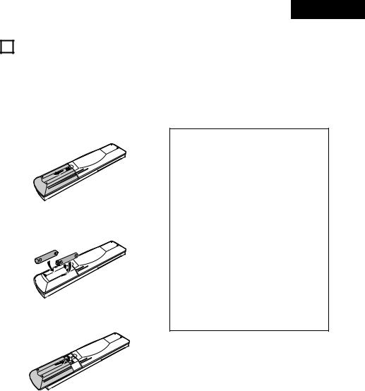
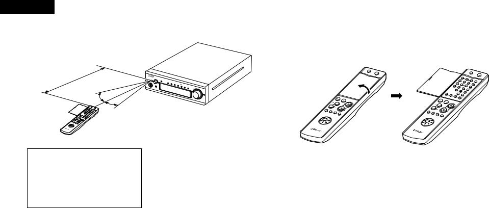
(1) Inserting Batteries
q Remove the remote control unit’s cover.
wInsert two R03 (AAA) batteries into the battery compartment in the direction indicated by the marks.
e Set the cover back in its original position.
Cautions on Batteries
•Use R03 (AAA) batteries in this remote control unit.
•Replace the batteries with new ones after approximately 1 year, though this depends on the frequency with which the remote control unit is used.
•Replace the batteries with new ones if the unit does not operate when the remote control unit is operated from nearby, even if the batteries are less than a year old.
•Be sure to insert the batteries in the proper direction, following the “ < ” and “ > ” marks in the battery compartment.
•To avoid damage or leakage of battery fluid:
•Do not use a new battery with an old one.
•Do not use two different types of batteries.
•Do not short-circuit, take apart, heat or dispose of batteries in flames.
•Remove the batteries when you do not plan to use the remote control unit for an extended period of time.
•If the battery fluid should leak, carefully wipe off the fluid from the inside of the battery compartment, then insert new batteries.
9
ENGLISH
(2) Using the Remote Control Unit
Approx. 7m/22 feet
30°
30°
 ++
++
--
NOTES:
•The remote control unit may not work properly if the remote sensor is exposed to direct sunlight or strong artificial light or if there is an obstacle between the remote control unit and the remote sensor.
•Do not press the buttons on the main unit and the remote control unit at the same time. Doing so will result in malfunction.
•Point the remote control unit at the remote sensor on the main unit as shown on the diagram when operating it.
(When system connections are made, the remote control signals for all the system components are received at the DRA-F101 remote sensor.)
•The remote control unit can be used from a straight distance of about 7 meters, but this distance will be shorter if the there is an obstacle in the way or if the remote control unit is not pointed directly at the remote sensor.
•Use the remote control unit within a range of 30° to the left and right of the remote sensor.
(3) Names and Functions of Remote Control Unit Buttons
2 Opening the remote control unit’s cover
|
VOLUME |
|
/ |
PRESET |
SELECT |
+ |
|
+ |
|
|
- |
|
|
|
- |
|
|
|
TAPE |
|
|
|
SLEEP |
FUNCTION |
|
|
|
MODE |
|
|
|
|
|
TUNER |
CD |
|
|
TAPE |
|
|
|
|
MD |
|
|
REMOTE |
RC-927 |
|
CONTROL UNIT |
OFF
SYSTEM |
ON |
OFF |
|
|
POWERSYSTEM |
ON |
|
|
|
|
|
|
1 |
|
|
|
|
|
|
|
|
2 |
|
|
|
|
|
|
|
4 |
|
3 |
PROG |
|
|
|
|
|
|
55 |
|
DIRECT / |
|
|
|
|
|
7 |
|
6 |
CALL |
|
|
|
|
|
8 |
|
|
|
|
|
|
|
|
+10 |
9 |
CLEAR |
|
|
|
|
|
|
0 |
RANDOM |
|
|
|
|
|
|
|
|
REPEAT |
|
|
|
|
|
|
|
TAPECD SRS |
|
|
|
|
|
|
|
|
MD |
|
|
|
|
|
|
|
|
DIMMER |
TIME EDIT |
|
|
|
|
|
|
RDS |
TIME/ |
|
|
|
|
|
|
|
|
BAND |
|
|
|
|
|
|
|
|
PANEL |
|
|
|
|
|
|
|
|
TUNING |
|
|
|
|
|
|
STOP |
PTY |
|
|
|
|
|
|
|
|
PLAY |
VOLUME |
|
|
|
|
|
|
|
|
|
|
|
|
|
|
|
|
|
/ |
|
|
|
|
|
|
PRESET |
SELECT |
|
|
|
|
|
|
|
+ |
|
|
|
|
|
|
|
- |
+ |
|
|
|
|
|
|
|
|
|
|
|
|
|
|
|
|
- |
|
|
|
|
|
|
|
|
TAPE |
|
|
|
|
|
|
|
|
SLEEP |
FUNCTION |
|
|
|
|
|
|
|
|
MODE |
|
|
|
|
|
|
|
|
|
|
|
|
|
|
|
TUNER |
CD |
|
|
|
|
|
|
|
TAPE |
|
|
|
|
|
|
|
|
|
MD |
|
|
|
|
|
|
REMOTE |
RC-927 |
|
|
|
|
|
|
|
|
CONTROL UNIT |
|
|
|
|
|
|
|
10
Number buttons
Press these buttons to recall preset station.
Examples:
To call the station at preset number 12:
Press +10 , 2
To call the station at preset number 29:
Press +10 , +10 , 9
BAND button (BAND)
Use this button to select the band.
 FM AUTO FM MONO AM
PRESET button (PRESET)
Use these buttons to recall preset stations on the tuner.
SLEEP button (SLEEP)
Press this button to set the sleep timer
ENGLISH
2 Buttons not described here function in the same way as the corresponding buttons on the main unit.
Power standby button (SYSTEM POWER STANDBY)
Press this to set the DRA-F101’s power to the standby mode. (When connected in a system with the D-F101 series, this button sets the power of the entire system to the standby mode.)
D-F101 series function operation block
When connected in a system with the DCD-F101, these buttons are used to operate the DCD-F101.
For operating instructions, refer to the manuals of the DCD-F101.
FUNCTION button
Press this to select the function source to be played.
The function switches in the following order each time the button is pressed:
MD |
TAPE |
PHONO |
Remote control function selector switch
Use this to select the function to be operated with this remote control unit. Set to TUNER to use the DRA-F101’s tuner function. For instructions on operating the various components, refer to their respective manuals.
OFF |
|
ON |
|
SYSTEM |
|
|
|
POWER |
|
|
PROG/ |
|
|
DIRECT |
1 |
2 |
3 |
|
|
CALL |
4 |
5 |
6 |
|
|
CLEAR |
7 |
8 |
9 |
RANDOM REPEAT
10 |
+10 |
CD SRS
TAPE MD TIME EDIT
|
|
TIME/ |
|
DIMMER PANEL |
|
RDS |
BAND |
TUNING |
STOP |
PLAY |
VOLUME |
|
|
/SELECT |
PRESET |
|
|
|
+ |
|
- |
|
|
TAPE |
SLEEP FUNCTION MODE |
|
|
||
|
CD |
|
TUNER |
|
MD |
TAPE |
|
|
RC-927
REMOTE CONTROL UNIT
Power on button (SYSTEM POWER ON)
When this button is pressed while the DRAF101’s power is in the standby mode, the DRAF101’s power turns on.
(When connected in a system with the D-F101 series, this button turns on the power of the entire system.)
DIMMER button
The display becomes darker (in 4 steps) each time this button is pressed.
Adjust the brightness of the display according to the brightness of the room.
VOLUME/SELECT buttons
•Press D to increase the volume, H to decrease it.
•These buttons are also used to set various modes.
MODE button
The mode switches as follows each time the button is pressed:
 BASS
BASS  TREBLE
  LOUDNESS
Playback function source
Models compatible with system remote control
• Receiver |
: |
DRA-F101 |
• CD player |
: |
DCD-F101 |
TUNING button (•,ª)
Use these buttons to selecting the station.
The buttons above for which there are no explanations cannot be operated with the DRA-F101.
11
ENGLISH |
|
|
|
|
|
|
|
|
|
|
7 |
OPERATION |
|
|
|
|
|
|
|||
(1) Playback |
|
|
|
|
|
|
Either turn the FUNCTION dial on the main unit |
|||
|
|
|
|
|
|
|
|
|
||
|
|
|
|
|
|
|
|
|
or press the remote control unit’s FUNCTION |
|
|
3 |
|
|
|
|
|
|
7 |
button to select the function source to be |
|
|
|
|
|
|
|
|
|
|
played. |
|
|
|
|
|
|
|
|
|
VOLUME |
• The function switches in the order shown |
|
|
FUNCTION |
|
|
MEMORY |
TUNING |
|
|
SOURCE |
below. |
|
|
TONE |
TIMER |
DISPLAY / SET |
DOWN |
UP |
BAND |
DIRECT |
|
||
|
SYSTEM |
|
|
|
|
|
|
|
The function switches in the opposite order |
|
|
ON / STANDBY |
|
|
|
|
|
|
|
when the dial is turned counterclockwise (.). |
|
|
PHONES |
|
|
|
|
|
|
|
||
|
|
|
|
|
|
|
|
AM-FM STEREO RECEIVER DRA-F101 |
|
|
|
2 |
|
|
|
|
|
|
5 |
3 |
|
|
|
|
|
|
|
|
|
|
|
|
|
|
|
|
|
|
|
|
|
FUNCTION |
FUNCTION |
|
|
|
|
OFF |
ON |
|
|
2 |
|
|
|
|
|
|
SYSTEM |
|
|
|
|
|
|
|
|
|
|
POWER |
|
|
|
|
|
|
|
|
PROG/ |
|
(Main unit) |
(Remote control unit) |
|
|
|
DIRECT |
|
|||
STOP PLAY VOLUME |
|
|
|
|
||
|
/SELECT |
|
|
|
|
|
PRESET |
|
|
|
|
|
|
|
+ |
|
|
CD |
TUNER |
|
- |
|
5 |
|
MD |
TAPE |
PHONO |
TAPE |
SLEEP FUNCTION |
MODE |
|
|
|
|
|
|
|
|
|
||
|
CD |
3 |
|
|
|
|
TUNER |
|
MD |
|
|
|
|
|
|
|
4 |
Start playback of the selected function source. |
||
|
|
|
• For instructions on operation, refer to the |
|||
1 Check that all connections are correct. |
|
component’s operating instructions. |
||||
|
|
|
|
|||
Turn on the power. |
|
|
Adjust the volume. |
|
|
|
• The indicator first flashes green, then after |
|
|
|
|||
|
|
|
|
|||
about 6 seconds stops flashing, remaining lit, |
|
|
|
VOLUME |
||
indicating that the unit is set to the power on |
|
|
|
/SELECT |
||
|
VOLUME |
|
|
|||
mode. |
|
|
5 |
|
|
|
|
|
|
|
|
||
SYSTEM |
|
|
|
|
|
|
|
|
|
|
|
|
|
ON / STANDBY |
|
ON |
|
|
|
|
|
|
SYSTEM |
|
|
|
|
|
|
POWER |
|
|
|
|
|
|
|
|
(Main unit) |
|
(Remote control unit) |
(Main unit) |
(Remote control unit) |
|
|
|
|
|
2 2 Power on/standby |
mode and function |
|
Adjust the BALANCE, BASS, and TREBLE |
|||
memory |
|
|
|
|||
B When the remote control unit is used to |
6 |
controls and set the LOUDNESS position to the |
||||
turn the DRA-F101’s power on from the |
desired position. |
|
|
|||
standby mode, the function is set to the |
|
For instructions on adjusting, see “(3) Setting |
||||
function that was selected when the |
|
the various modes” on page 12, 13. |
||||
power was last set to the standby mode. |
|
|
|
|
||
(Last memory function) |
|
|
|
|
||
B If the function has been cleared from the |
|
To use the source direct function: |
||||
memory, the function is set to “CD” when |
|
Press the SOURCE DIRECT button to display |
||||
the DRA-F101’s power is turned on. |
|
“SD ON” . |
|
|
||
|
|
|
7 |
|
|
SOURCE |
|
|
|
|
|
DIRECT |
|
|
|
|
|
|
|
(Main unit) |
(2) Recording
1 Follow step 1 to 4 under “(1) Playback”.
Start recording on the cassette deck or MD recorder.
For instructions, refer to the component’s operating instructions.
•Operating the VOLUME, BALANCE, BASS, TREBLE and the LOUDNESS controls will not
2 |
affect the sound being recorded. |
•When the function source is set to “MD”, recording is performed from the MD recorder onto the cassette deck. When the function source is set to “TAPE”, recording is performed from the cassette deck onto the MD recorder.
(3) Setting the various modes
2 |
|
1 |
|
|
|
|
|
|
|
|
|
|
|
|
|
|
VOLUME |
FUNCTION |
|
|
|
MEMORY |
TUNING |
|
|
SOURCE |
TONE |
TIMER |
DISPLAY |
/ SET |
DOWN |
UP |
BAND |
DIRECT |
|
SYSTEM |
|
|
|
|
|
|
|
|
ON / STANDBY |
|
|
|
|
|
|
|
|
PHONES |
|
|
|
|
|
|
|
|
|
|
|
|
|
|
|
|
AM-FM STEREO RECEIVER DRA-F101 |
STOP |
PLAY |
VOLUME |
|
|
/SELECT |
PRESET |
|
|
|
+ |
|
- |
|
2 |
TAPE
SLEEP FUNCTION MODE
1
[1] Adjusting the bass and treble
Press the TONE or MODE button to display the mode to be adjusted (“BASS” or “TREBLE”).
TONE MODE
(Main unit) (Remote control unit)
1 |
• The mode switches as follows each time the |
||||||||||||||
|
button is pressed: |
|
|
|
|
|
|
|
|||||||
|
|
|
|
|
|
|
|
|
|
|
|
|
|||
|
|
|
BASS |
|
|
|
TREBLE |
|
|
LOUDNESS |
|
|
|||
|
|
|
|
|
|
|
|
|
|
|
|
|
|
||
|
|
|
|
|
Playback |
|
|
|
|
BALANCE |
|
|
|
||
|
|
|
|
|
|
|
|
|
|
|
|
||||
|
|
|
|
|
|
|
|
|
|
|
|
|
|
||
|
|
|
|
function source |
|
|
|
|
|
|
|
||||
This cannot be selected when the source direct mode is set to “ON”.
Either turn the FUNCTION dial on the main unit or use the remote control unit’s SELECT buttons.
|
VOLUME |
|
/SELECT |
|
(increase) |
(decrease) FUNCTION |
(increase) |
|
(decrease) |
(Main unit) |
(Remote control unit) |
2
• To increase the bass or treble:
Turn the dial clockwise (,) or press the D button.
To decrease the bass or treble:
Turn the dial counterclockwise (.) or press the H button.
•The bass and treble can be adjusted within the range of –8 to 0 to +8 in steps of 2. The response is flat at 0.
12

[2] Setting the loudness mode
Press the TONE or MODE button to display “LOUDNESS”.
TONE MODE
1 |
|
(Main unit) |
(Remote control unit) |
•The mode switches as shown at the left each time the button is pressed.
“LOUDNESS” cannot be selected when the source direct mode is on.
Either turn the FUNCTION dial on the main unit or use the remote control unit’s SELECT buttons.
VOLUME
/SELECT
 (ON)
(ON)
FUNCTION
(OFF) |
(ON) |
2 |
(OFF) |
|
|
(Main unit) |
(Remote control unit) |
• To set to “ON”:
Turn the dial clockwise (,) or press the D button.
To set to “OFF”:
Turn the dial counterclockwise (.) or press the H button.
[3] Adjusting the balance
Press the TONE or MODE button to display “BALANCE” (Refer to page 12.)
TONE MODE
1 |
|
(Main unit) |
(Remote control unit) |
“BALANCE” cannot be selected when the source direct mode is on.
Either turn the FUNCTION dial on the main unit or use the remote control unit’s SELECT buttons.
|
(right |
VOLUME (left channel |
|
|
/SELECT |
volume |
|
(left channel |
channel |
|
adjustment) |
volume |
volume |
|
|
adjustment) FUNCTION |
adjustment) |
|
|
|
|
|
(right |
|
|
|
channel |
(Main unit) |
|
(Remote |
volume |
|
adjustment) |
||
2 |
|
control unit) |
|
|
|
|
|
• If the volume of the right speaker is low: |
|||
Turn the dial clockwise (,) or press the D |
|||
button. |
|
|
|
If the volume of the left speaker is low: |
|||
Turn the dial counterclockwise (.) or press |
|||
the H button. |
|
|
|
•The balance can be set to “CENTER” or adjusted within the range of +1 to +10 in steps of 1. When set “CENTER”, the difference between the volume of the left and right speakers is 0.
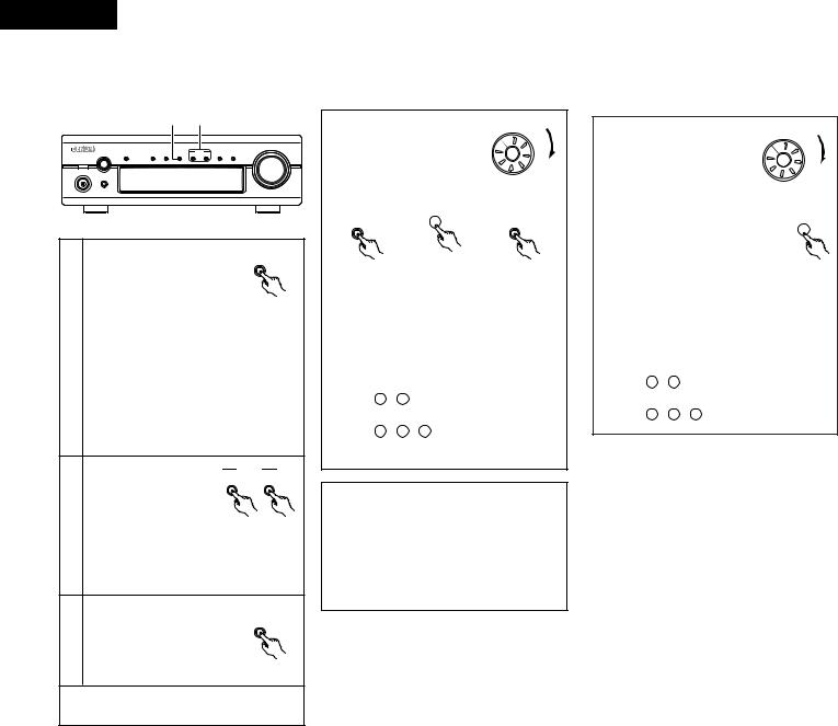
8 LISTENING TO RADIO
(1) Tuning
3 2
VOLUME
|
|
|
|
FUNCTION |
|
|
|
MEMORY |
|
TUNING |
|
|
SOURCE |
|
|
|
|
TONE |
TIMER |
DISPLAY |
/ SET |
DOWN |
UP |
BAND |
DIRECT |
||
|
|
|
|
|
|
|
|
|
|
|
|
|
|
|
|
|
|
|
|
|
|
|
|
|
|
|
|
|
|
|
|
|
|
|
|
|
|
|
|
|
|
SYSTEM
ON / STANDBY
PHONES |
AM-FM STEREO RECEIVER DRA-F101 |
1 |
|
OFF |
ON |
|
|
SYSTEM |
1 |
|
|
POWER |
||
|
|
|
|
|
|
|
PROG/ |
|
|
|
DIRECT |
1 |
2 |
3 |
|
|
|
|
CALL |
4 |
5 |
6 |
|
|
|
|
CLEAR |
7 |
8 |
9 |
|
|
RANDOM |
REPEAT |
|
10 |
+10 |
|
|
|
CD SRS |
TIME EDIT |
|
|
TAPE |
MD |
|
|
DIMMER |
TIME/ |
|
|
PANEL |
||
RDS |
BAND |
TUNING |
|
2 |
|
|
3 |
|
|
|
|
STOP |
PLAY |
VOLUME |
|
|
|
/SELECT |
|
Example: Tuning in FM 92.50 MHz
(AM stations are tuned in using the same procedure.)
Press the power operation switch to turn on the power.
SYSTEM |
|
ON / STANDBY |
ON |
1 |
SYSTEM |
|
POWER |
(Main unit) |
(Remote control unit) |
Press the BAND button on the tuner to select the FM AUTO.
|
BAND |
BAND |
2 |
(Main unit) |
(Remote control unit) |
ENGLISH
Auto Tuning
•When a program being broadcast in stereo is received, the “STEREO” indicator lights and the program is received in stereo.
•If reception is poor and there is much noise in the stereo signals, press the BAND button to set the FM MONO mode.
•When one of the TUNING UP/DOWN button is pressed, the frequency changes in steps of 100 kHz in the FM band, 10 kHz in the AM band.
•If one of the TUNING UP/DOWN button is held for over 1 second, the frequency continues to change when the button is released (auto tuning) and stops when a station is tuned in. Tuning will not stop at stations whose reception is poor.
•To stop the auto tuning function, press the TUNING UP/DOWN button once.
NOTE:
A humming sound may be heard when using a TV nearby while receiving AM programs. If this happens, move the system as far from the TV as possible.
Use the TUNING UP/DOWN button to tune the frequency to 92.50.
TUNING |
|
|
DOWN |
UP |
TUNING |
3 |
(Main unit) |
(Remote control unit) |
This lights when a station is tuned in.
13
ENGLISH
(2) Presetting AM and FM stations
Example: To preset the currently tuned in FM station at preset number “3”
|
|
|
1, 3 |
2 |
|
|
|
|
|
|
|
|
|
|
|
|
VOLUME |
FUNCTION |
|
|
|
MEMORY |
TUNING |
|
|
SOURCE |
TONE |
TIMER |
DISPLAY |
/ SET |
DOWN |
UP |
BAND |
DIRECT |
|
SYSTEM
ON / STANDBY
PHONES
AM-FM STEREO RECEIVER DRA-F101
MEMORY
Press the MEMORY/SET button. |
/ SET |
• The “P.SET”, “MEMO” |
|
indicator flashes. |
|
•Depending on what preset number is displayed before the button is pressed, the preset number section flashes as shown
1below and the setting standby mode is set. When “01” to “10” or “0-” is displayed,
“0-” flashes.
When “11” to “20” or “1-” is displayed, “1-” flashes.
When “21” to “30” or “2-” is displayed, “2-” flashes.
When “31” to “40” or “3-” is displayed, “3-” flashes.
While the “MEMO” indicator |
TUNING |
|
DOWN |
UP |
|
is flashing, press the TUNING |
|
|
UP button three times to |
|
|
display “P.SET”, “03”. |
|
|
2
To store the station at a different preset number, use the tuning buttons (TUNING UP or DOWN) to set the desired preset number.
Press the MEMORY/SET button |
MEMORY |
/ SET |
|
again while the “MEMO” |
|
3 indicator is flashing. |
|
•The “MEMO” indicator turns off and the station is preset.
A total of 40 AM and FM stations can be preset using this procedure.
When operating with the |
TUNER |
CD |
|
system remote control unit, |
MD |
||
|
|
||
first set the remote control |
TAPE |
|
|
|
|
||
unit’s function selector switch |
|
|
|
to “TUNER”. |
|
|
|
|
|
|
(RC-927) |
Procedure |
|
|
|
MEMORY |
|
|
MEMORY |
/ SET |
3 |
|
/ SET |
|
|
|
|
|
/ |
/ |
|
DRA-F101 |
(RC-927) |
|
DRA-F101 |
(this unit) |
|
|
(this unit) |
•This setting can also be made by pressing the
 TUNING

 button instead of pressing “e”.
•To store the station at a different preset number,
use the number buttons and the +10 button on the system remote control unit (RC-927) to set the desired preset number.
Examples:
To store the station at preset number 12:
Press +10 , 2
To store the station at preset number 29:
Press +10 , +10 , 9
Presetting
•When a station is preset, both the reception frequency and reception mode are stored in the memory.
•If a station is preset at a number where another station is already preset, the previous station is erased and the new station is set.
•The preset memory is not erased immediately if the power supply is cut off momentarily.
(3) Tuning in Preset Stations
Example: To tune in the station stored at preset number “3”
When operating with the |
TUNER |
CD |
||
system remote control unit, |
MD |
|||
|
|
|||
first set the remote control |
TAPE |
|
||
|
|
|||
unit’s function selector switch |
|
|
||
to “TUNER”. |
|
|
|
|
|
|
|
|
(RC-927) |
Procedure: |
|
|
|
|
• Instead |
of pressing |
e, the |
preset |
|
|
|
|
|
3 |
channel |
can also be |
called |
out |
by |
pressing the < or > button to display
“P.SET 03”.
•To call the station at a different preset number, use the number buttons and the +10 button on the
system remote control unit (RC-927) to set the
desired preset number.
Examples:
To call the station at preset number 12:
Press +10 , 2
To call the station at preset number 29:
Press +10 , +10 , 9
14

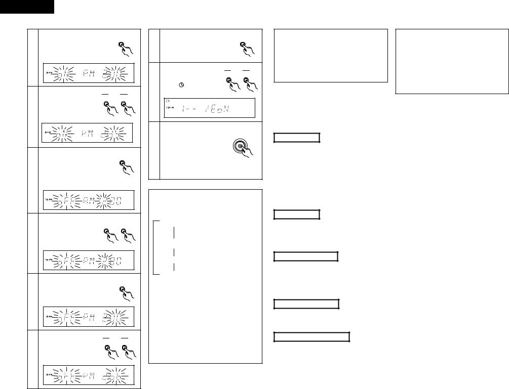
9 USING THE TIMER |
Use the TUNING buttons |
TUNING |
|
|
to input the hours (PM 9). |
DOWN |
UP |
(1) Setting the Current Time (12-hour display) |
|
|
|
• “9” flashes in the hours |
|
|
|
|
position. |
|
|
4
Example: Setting the current time to 9:30 p.m.
2 3,5,7 4,6
VOLUME
FUNCTION |
|
|
|
MEMORY |
|
TUNING |
|
|
SOURCE |
TONE |
TIMER |
DISPLAY |
/ SET |
DOWN |
UP |
BAND |
DIRECT |
||
|
|
|
|
Press the MEMORY/SET button. |
MEMORY |
SYSTEM |
|
|
|
/ SET |
|
ON / STANDBY |
|
|
|
• “9” stops flashing, remaining lit, |
|
|
PHONES |
|
|
|
|
|
|
AM-FM STEREO RECEIVER DRA-F101 |
|
and the minutes position starts |
|
|
|
|
5 |
flashing. |
|
1 |
|
|
|
|
|
|
|
|
|
|
|
SYSTEM |
|
|
|
|
|
|
ON / STANDBY |
|
|
|
|
|
1 |
Turn on the power. |
|
Use the TUNING buttons to |
TUNING |
||
|
DOWN |
UP |
||||
|
|
|
input the minutes (30). |
|
|
|
|
|
|
• “30” flashes in |
the |
|
|
|
|
6 |
minutes position. |
|
|
|
|
TIMER |
|
|
|
|
|
|
Press the TIMER button for at least |
|
|
|
|
|
|
3 seconds. |
|
|
|
|
|
|
• “TIME” flashes on the display. |
|
|
|
|
|
2 |
If the time is already set, |
|
|
|
|
|
“EVERYDAY” is displayed. |
|
Press the MEMORY/SET button |
|
|||
|
Press one of the TUNING buttons |
|
|
|||
|
|
at the sound of the chime of a |
|
|||
|
to display “TIME”, then perform |
|
MEMORY |
|||
|
|
time service, etc. |
|
|
||
|
step 3. |
|
|
|
/ SET |
|
|
|
|
|
|
||
|
|
• “30” stops flashing, remaining |
|
|||
|
|
|
|
|||
|
MEMORY |
7 |
lit, and the current time is |
|
||
|
displayed. |
|
|
|
||
|
/ SET |
|
|
|
||
|
Press the MEMORY/SET button. |
|
|
|
|
|
|
• The hours position flashes. |
|
|
|
|
|
3 |
|
|
|
|
|
|
|
|
The number changes continuously when one of the |
||||
|
|
|
tuning buttons (TUNING UP or DOWN) is pressed. |
|||
|
|
If the time is already set when step 2, 3 is performed, |
||||
|
|
|
both the hours and minutes positions flash. |
|
||
(2) Before Setting the Timer |
|
|
|
|
|
|
2 Be sure to set the current time. If the current time is not set, the timer standby indicator (“ |
”) will not light and the |
|||||
timer will not function. |
|
|
|
|
|
|
2Be sure to preset the station before setting the timer. (Refer to “Presetting AM and FM stations” on page 14.)
2The DRA-F101 is equipped with two types of timers: the everyday time which turns the power on and off at the same times every day, and the once timer that turns the power on and off only once.
2Do not change the timer standby mode after the timer is activated (after the timer on time is reached). The timer may not operate properly.
2It is not possible to set the timer start and end times to the same time.
2If the display or operation is not normal, unplug the power cord, then plug it back in while pressing the memory/set button (MEMORY/SET). This restores the tuner to the initial default values. After doing this, reset the presettings, current time and timer settings.
2When setting the timer to operate the CD player do so with a disc loaded and the disc holder closed. The timer will not operate properly if no disc is loaded or if the disc holder is open.
ENGLISH
(3) Setting the Timer
2The timer function lets you switch the power between the on and standby modes automatically at the desired times.
2When connected in a system with the DCD-F101, the timer can be used to play a CD.
Example: Using the everyday timer to listen to the station stored at preset number 3 (FM 98.00 MHz) from 2:35 p.m. to 2:56 p.m.
2 3, 5, 7, 9,11,13,15,17
VOLUME
FUNCTION |
|
|
|
MEMORY |
|
TUNING |
|
|
SOURCE |
TONE |
TIMER |
DISPLAY |
/ SET |
DOWN |
UP |
BAND |
DIRECT |
||
SYSTEM |
|
ON / STANDBY |
|
|
PHONES |
|
AM-FM STEREO RECEIVER DRA-F101 |
1,18 |
4, 6, 8,10,12,14,16 |
SYSTEM
ON / STANDBY
1 |
Turn on the power. |
TIMER
Press the TIMER button for at least 3 seconds.
• “EVERYDAY” is displayed.
2
If the time is not set, “TIME” is displayed. Perform steps 3 to 7 on page 15, then start the timer setting over.
|
TUNING |
|
Press one of the TUNING |
DOWN |
UP |
|
|
|
3 buttons to display |
|
|
“EVERYDAY” or “ONCE”. |
|
|
Press the MEMORY/SET button. |
MEMORY |
|
/ SET |
||
• This sets the unit to the timer |
|
|
setting mode’s function |
|
|
setting mode. |
|
|
4 Example: When the everyday timer is selected
|
TUNING |
|
Use the TUNING buttons |
DOWN |
UP |
|
|
|
to switch the function to |
|
|
“TUNER”. |
|
|
5 |
The function switches as follows each time |
|
|
||
|
the button is pressed: |
|
|
: When the TUNING UP button is pressed. |
|
|
: When the TUNING DOWN button is |
|
|
pressed. |
|
|
Press the MEMORY/SET button. |
MEMORY |
|
/ SET |
|
|
|
|
6 • “TUNER” is stored in the |
|
|
|
memory as the timer function. |
|
|
TUNING |
|
|
DOWN |
UP |
|
Use the TUNING buttons |
|
|
to set preset number 3. |
|
7
|
Press |
the |
MEMORY/SET |
MEMORY |
|
button. |
|
|
/ SET |
|
|
|
|
|
|
• The preset station is stored in |
|
||
|
the memory and the timer on |
|
||
|
time setting mode is set. |
|
||
8 |
“E” |
and |
“oN” appear |
|
alternately in the display in the |
|
|||
|
steps 8 to 11. |
|
|
|
<Setting the timer on |
|
TUNING |
|
|
|
||
time> |
DOWN |
UP |
|
|
|
|
|
Use the tuning buttons to set the hours position to “PM
2”.
9
15
ENGLISH
MEMORY
Press the MEMORY/SET button. |
/ SET |
|
|
• “PM 2” is stored in the |
|
memory for the hours position. |
|
10
TUNING |
|
Use the TUNING buttons to DOWN |
UP |
set the minutes position to |
|
“35”. |
|
11
|
Press the MEMORY/SET button. |
MEMORY |
|
• The on time is stored in the |
/ SET |
|
|
|
|
memory and the timer off time |
|
|
setting mode is set. |
|
12 |
“E” and “oFF” appear alternately |
|
in the display in the steps 12 to 15. |
|
<Setting the timer off |
|
TUNING |
|
|
|
||
time> |
DOWN |
UP |
|
|
|
|
|
Use the TUNING buttons to set the hours position to
13 “PM 2”.
MEMORY
Press the MEMORY/SET button. |
/ SET |
|
|
• “PM 2” is stored in the memory |
|
for the hours position. |
|
14
|
TUNING |
|
Use the TUNING buttons to |
DOWN |
UP |
|
|
|
set the minutes position to |
|
|
“56”. |
|
|
15
|
Press the MEMORY/SET button. |
MEMORY |
||
|
/ SET |
|||
16 |
|
|||
• The off time is stored in the |
|
|||
|
memory. |
|
|
|
|
Use the TUNING button to |
TUNING |
||
|
DOWN |
UP |
||
|
select ”E oN”. |
|
|
|
17 |
• The “ |
” mark lights. |
|
|
|
|
|
|
|
|
Turn off the power. |
|
|
|
|
When |
the DRA-F101 is |
|
SYSTEM |
|
connected in a system with |
ON / STANDBY |
||
|
|
|
||
18 |
the D-F101 series, press the |
|
|
|
power button on the receiver. |
|
|
||
•The standby mode is set. (The power switch indicator turn orange and display turn off.)
Turning on and off the timer standby ON/OFF
•In TIMER STANDBY mode, each time the TUNING button is pressed, the setting changes as follows:
1 1 oN/E oN:
1
1
1_ _/E oN:
1 1
1 oN/E_ _:
1 1
1 1_ _/E_ _:
Both once and everyday timers are activated. (The  mark lights.)
Only the everyday timer is activated. (The  mark lights.) Only the once timer is activated. (The
  mark lights.)
Both timers are canceled. (The  mark turns off.)
•When you set only the everyday timer, the indication changes between 1_ _/E_ _ and 1_ _/E oN.
•When you set only the once timer, the indication changes between 1_ _/E_ _ and 1 oN/E_ _.
•When you complete the setting, the display automatically returns to the former state after 5 seconds.
•To change the settings of TIMER STANDBY, press TIMER button to set the unit in TIMER STANDBY mode first, the use TUNING button to make changes.
When the timer start time is reached, the timer operates.
If “ONCE” is selected in step 3, the once timer setting mode is selected. Set the timer using the same procedure. At steps 4 and 8 through 15, “1” (for once) is displayed instead of “E”.
The once timer is activated when “1 oN” is displayed at step 17.
NOTES:
• The timer standby indicator (“  ”) will not light if the current time is not set. If this happens, set the current time. (Refer to “Setting the Current Time” on page 15.)
•When the timer on time is reached while in the standby mode, operation switches to the operation set with the timer. (The timer setting has priority.)
•Set the standby mode when using the timer. The timer may not operate properly if the power is on.
(4) Using the timer
The time and timer functions are incorporated in this unit.
Timer Settings
2 Types of timer operations
EVERYDAY TIMER : Use this to turn the power on and standby at the same times every day.
ONCE TIMER |
: Use this to turn the power on and standby once. |
SLEEP TIMER |
: Use this to set the power to turn standby after 10 to 60 minutes, in steps of 10 minutes (operated |
|
from the remote control unit). |
2 Notes on timer settings
•Be sure to set the current time beforehand.
•To listen to a radio program using the timer, be sure to preset the station beforehand. (Refer to “Presetting AM and FM Stations” on Page 14.)
Power Failures
If the power cord is unplugged or there is a power failure, the settings of the current time and once timer are erased and the time display will flash. If this happens, reset the current time and the once timer.
Also check the timer and tuner presettings, and reset them if they have been cleared.
Checking the Settings
To check the timer settings, press the TIMER button for at least 3 seconds to select EVERYDAY or ONCE TIMER.
Next, press the TUNING button to select EVERYDAY or ONCE TIMER, then press MEMORY/SET button repeatedly to display in order: Timer Start mode, and (when in TUNER mode) the reception band and preset channel number, Timer On time, Timer Off time, Press the MEMORY/SET button again to return to the current mode display.
Changing the Settings
Repeat the timer setting operation to erase the previous settings and set the new settings.
Note on Setting the Timer
If the time set with the timer is reached while the system power is on, the operation switches to the operation set by the timer.
16
 Loading...