


STEREO CASSETTE TAPE DECK
DRM-555
OPERATING INSTRUCTIONS
MODE D’EMPLOI
INSTRUCCIONES DE OPERACION
|
DRM-555 |
|
|
|
|
|
|
|
|
|
|
|
|
|
|
|
INPUT LEVEL |
|
PRECISION AUDIO COMPONENT/CASSETTE TAPE DECK |
|
|
|
|
|
|
|
|
|
|
|
|
|
|
|
5 |
|
|
|
|
|
|
|
|
|
|
|
|
|
|
|
|
|
|
4 |
|
6 |
EJECT |
|
|
|
|
|
|
|
|
|
|
|
|
|
RESET |
3 |
|
|
7 |
5 |
|
|
|
|
|
|
|
|
|
|
|
|
|
|
|
|||
|
dB |
-40 |
-30 -20 -10 |
-5 |
-3 |
-1 |
0 |
+1 |
+3 |
+5 |
+10 |
|
|
|
|
|
|
|
|
L |
|
|
|
|
|
|
|
|
|
|
|
|
COUNTER |
|
|
|
|
|
HIGH SPEED DUBBING SYSTEM |
|
|
|
|
|
|
|
|
|
|
|
|
|
|
|
|
|
|
R |
|
|
|
|
|
|
|
|
|
|
|
|
MEMORY |
2 |
|
|
8 |
|
|
|
|
|
|
|
|
|
|
|
|
|
|
|
|
|||
|
|
|
|
|
|
|
|
‚¤‚‚ |
|
|
|
|
|
|
|
|||
|
|
|
|
|
|
|
|
|
|
|
|
|
|
MPX |
1 |
|
|
9 |
|
|
|
|
|
|
|
|
|
|
|
|
|
|
|
|
|
||
TIMER |
REMOTE SENSOR |
|
|
|
|
|
|
|
|
|
DOLBY NR |
REV.MODE |
|
|
|
|
||
REC OFF PLAY. |
|
|
|
|
|
|
|
|
|
|
B |
OFF |
C |
|
|
0 |
|
10 |
|
AUTO REVERSE |
|
|
|
|
|
|
|
|
|
|
|
|
|
|
|
|
|
¢ON £OFF |
|
|
|
|
|
|
|
|
|
|
|
|
PHONE LEVEL |
BIAS FINE |
|
|
BALANCE |
|
PLAY |
|
2 STOP |
|
3 REC PAUSE |
|
|
PHONES |
|
|
|
|
|
|
|
||||
|
|
|
|
|
|
|
|
|
|
|
|
|||||||
|
|
|
DIRECTION |
|
REC/REC MUTE |
|
|
|
|
|
|
|
|
|
|
|||
|
|
|
|
|
|
|
|
|
|
|
|
|
MIN |
MAX |
- |
+ |
LEFT |
RIGHT |
|
|
|
|
|
CD SYNCHRO REC |
|
|
|
|
|
|
|
|
|
|
|||
FOR ENGLISH READERS |
PAGE |
05 |
~ PAGE |
16 |
POUR LES LECTEURS FRANCAIS |
PAGE |
17 |
~ PAGE |
28 |
PARA LECTORES DE ESPAÑOL |
PAGINA |
29 |
~ PAGINA 37 |
|
IMPORTANT TO SAFETY
WARNING:
TO PREVENT FIRE OR SHOCK HAZARD, DO NOT EXPOSE THIS APPLIANCE TO RAIN OR MOISTURE.
CAUTION:
1.Handle the power supply cord carefully
Do not damage or deform the power supply cord. If it is damaged or deformed, it may cause electric shock or malfunction when used. When removing from wall outlet, be sure to remove by holding the plug attachment and not by pulling the cord.
2.Do not open the top cover
In order to prevent electric shock, do not open the top cover. If problems occur, contact your DENON DEALER.
3.Do not place anything inside
Do not place metal objects or spill liquid inside the cassette tape deck. Electric shock or malfunction may result.
Please, record and retain the Model name and serial number of your set shown on the rating label.
Model No. DRM-555 Serial No.
CAUTION
RISK OF ELECTRIC SHOCK
DO NOT OPEN
CAUTION: TO REDUCE THE RISK OF ELECTRIC SHOCK, DO NOT REMOVE COVER (OR BACK). NO USER-SERVICEABLE PARTS INSIDE. REFER SERVICING TO QUALIFIED SERVICE PERSONNEL.
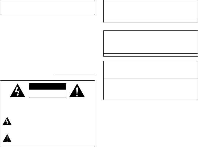
The lightning flash with arrowhead symbol, within an equilateral triangle, is intended to alert the user to the presence of uninsulated “dangerous voltage” within the product’s enclosure that may be of sufficient magnitude to constitute a risk of electric shock to persons.
The exclamation point within an equilateral triangle is intended to alert the user to the presence of important operating and maintenance (servicing) instructions in the literature accompanying the appliance.
• FOR U.S.A. & CANADA MODEL ONLY
CAUTION
TO PREVENT ELECTRIC SHOCK DO NOT USE THIS (POLARIZED) PLUG WITH AN EXTENSION CORD, RECEPTACLE OR OTHER OUTLET UNLESS THE BLADES CAN BE FULLY INSERTED TO PREVENT BLADE EXPOSURE.
• POUR LES MODELES AMERICAINS ET CANADIENS UNIQUEMENT
ATTENTION
POUR PREVENIR LES CHOCS ELECTRIQUES NE PAS UTILISER CETTE FICHE POLARISEE AVEC UN PROLONGATEUR UNE PRISE DE COURANT OU UNE AUTRE SORTIE DE COURANT, SAUF SI LES LAMES PEUVENT ETRE INSEREES A FOND SANS EN LAISSER AUCUNE PARTIE A DECOUVERT.
This device complies with Part 15 of the FCC Rules. Operation is subject to the following two conditions: (1) This device may not cause harmful interference, and (2) this device must accept any interference received, including interference that may cause undesired operation.
This Class B digital apparatus meets all requirements of the Canadian Interference-Causing Equipment Regulations.
Cet appareil numérique de la classe B respecte toutes les exigences du Règlement sur le matériel brouilleur du Canada.
2
SAFETY INSTRUCTIONS
1.Read Instructions – All the safety and operating instructions should be read before the appliance is operated.
2.Retain Instructions – The safety and operating instructions should be retained for future reference.
3.Heed Warnings – All warnings on the appliance and in the operating instructions should be adhered to.
4.Follow Instructions – All operating and use instructions should be followed.
5.Water and Moisture – The appliance should not be used near water – for example, near a bathtub, washbowl, kitchen sink, laundry tub, in a wet basement, or near a swimming pool, and the like.
6.Carts and Stands – The appliance should be used only with a cart or stand that is recommended by the manufacturer.
6A. An appliance and cart combination should be moved with care. Quick stops, excessive force, and uneven surfaces may cause the appliance and cart
combination to overturn.
7.Wall or Ceiling Mounting – The appliance should be mounted to a wall or ceiling only as recommended by the manufacturer.
8.Ventilation – The appliance should be situated so that its location or position does not interfere with its proper ventilation. For example, the appliance should not be situated on a bed, sofa, rug, or similar surface that may block the ventilation openings; or, placed in a built-in installation, such as a bookcase or cabinet that may impede the flow of air through the ventilation openings.
9.Heat – The appliance should be situated away from heat sources such as radiators, heat registers, stoves, or other appliances (including amplifiers) that produce heat.
10.Power Sources – The appliance should be connected to a power supply only of the type described in the operating instructions or as marked on the appliance.
11.Grounding or Polarization – Precautions should be taken so that the grounding or polarization means of an appliance is not defeated.
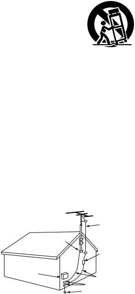
FIGURE A
EXAMPLE OF ANTENNA GROUNDING
AS PER NATIONAL
ELECTRICAL CODE ANTENNA
LEAD IN
WIRE
GROUND
CLAMP
ANTENNA DISCHARGE UNIT
(NEC SECTION 810-20)
ELECTRIC
SERVICE
EQUIPMENT
GROUNDING CONDUCTORS (NEC SECTION 810-21)
GROUND CLAMPS
POWER SERVICE GROUNDING ELECTRODE SYSTEM
(NEC ART 250, PART H)
NEC - NATIONAL ELECTRICAL CODE
12.Power-Cord Protection – Power-supply cords should be routed so that they are not likely to be walked on or pinched by items placed upon or against them, paying particular attention to cords at plugs, convenience receptacles, and the point where they exit from the appliance.
14.Cleaning – The appliance should be cleaned only as recommended by the manufacturer.
15.Power Lines – An outdoor antenna should be located away from power lines.
16.Outdoor Antenna Grounding – If an outside antenna is connected to the receiver, be sure the antenna system is grounded so as to provide some protection against voltage surges and built-up static charges. Article 810 of the National Electrical Code, ANSI/NFPA 70, provides information with regard to proper grounding of the mast and supporting structure, grounding of the lead-in wire to an antenna-discharge unit, size of grounding conductors, location of antenna-discharge unit, connection to grounding electrodes, and requirements for the grounding electrode. See Figure A.
17.Nonuse Periods – The power cord of the appliance should be unplugged from the outlet when left unused for a long period of time.
18.Object and Liquid Entry – Care should be taken so that objects do not fall and liquids are not spilled into the enclosure through openings.
19.Damage Requiring Service – The appliance should be serviced by qualified service personnel when:
A.The power-supply cord or the plug has been damaged; or
B.Objects have fallen, or liquid has been spilled into the appliance; or
C.The appliance has been exposed to rain; or
D.The appliance does not appear to operate normally or exhibits a marked change in performance; or
E.The appliance has been dropped, or the enclosure damaged.
20.Servicing – The user should not attempt to service the appliance beyond that described in the operating instructions. All other servicing should be referred to qualified service personnel.
3
ENGLISH FRANCAIS ESPAÑOL
NOTE ON USE / OBSERVATIONS RELATIVES A L’UTILISATION / NOTAS SOBRE EL USO
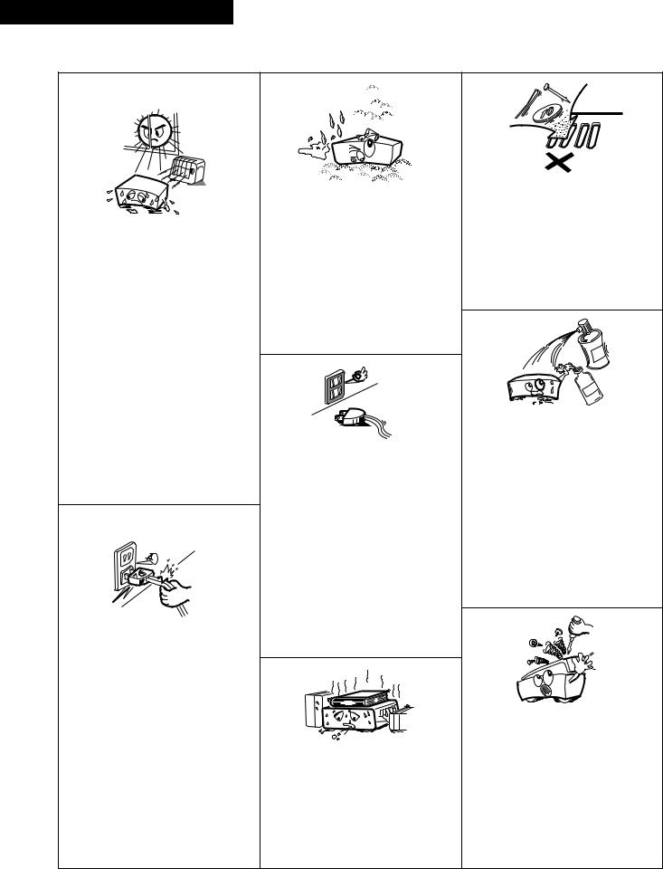
•Avoid high temperatures.
Allow for sufficient heat dispersion when installed on a rack.
•Eviter des températures élevées Tenir compte d’une dispersion de chaleur suffisante lors de l’installation sur une étagère.
•Evite altas temperaturas.
Permite la suficiente dispersión del calor cuando está instalado en la consola.
•Handle the power cord carefully. Hold the plug when unplugging the cord.
•Manipuler le cordon d’alimentation avec précaution.
Tenir la prise lors du débranchement du cordon.
•Maneje el cordón de energía con cuidado.
Sostenga el enchufe cuando desconecte el cordón de energía.
•Keep the set free from moisture, water, and dust.
•Protéger l’appareil contre l’humidité, l’eau et lapoussière.
•Mantenga el equipo libre de humedad, agua y polvo.
•Unplug the power cord when not using the set for long periods of time.
•Débrancher le cordon d’alimentation lorsque l’appareil n’est pas utilisé pendant de longues périodes.
•Desconecte el cordón de energía cuando no utilice el equipo por mucho tiempo.
*(For sets with ventilation holes)
•Do not obstruct the ventilation holes.
•Ne pas obstruer les trous d’aération.
•No obstruya los orificios de ventilación.
•Do not let foreign objects in the set.
•Ne pas laisser des objets étrangers dans l’appareil.
•No deje objetos extraños dentro del equipo.
•Do not let insecticides, benzene, and thinner come in contact with the set.
•Ne pas mettre en contact des insecticides, du benzène et un diluant avec l’appareil.
•No permita el contacto de insecticidas, gasolina y diluyentes con el equipo.
•Never disassemble or modify the set in any way.
•Ne jamais démonter ou modifier l’appareil d’une manière ou d’une autre.
•Nunca desarme o modifique el equipo de ninguna manera.
4
ENGLISH
Thank you very much for purchasing the DENON component stereo cassette |
Please check to make sure the following items are included with the main |
||
tape deck. |
unit in the carton: |
|
|
DENON proudly presents this advanced tape deck to audiophiles and music |
(1) |
Operating Instructions …………………………………………………1 |
|
lovers as a further proof of DENON’s non-compromising pursuit of the ultimate |
(2) |
Connection Cords |
………………………………………………………2 |
in sound quality. The high quality performance and easy operation are certain to |
(3) |
Mini-Plug Cable |
…………………………………………………………1 |
provide you with many hours of outstanding listening pleasure. |
|
|
|
— TABLE OF CONTENTS — |
FEATURES |
|
|
|
|||
FEATURES ……………………………………………………………………………5 |
2 |
Computer Controlled Mechanism |
|
CONNECTION ………………………………………………………………………5 |
2 |
Dual Power Supply |
|
NAMES AND FUNCTIONS OF PARTS …………………………………………6, 7 |
2 |
Dolby HX-Pro Headroom Extension System |
|
CASSETTE TAPES ……………………………………………………………………7 |
2 |
Dolby B & C Noise Reduction Systems |
|
AUTOMATIC TAPE SELECTION ……………………………………………………8 |
2 |
Manual Bias Adjustment Control |
|
PLAYBACK …………………………………………………………………………8, 9 |
2 |
Computing Tape Counter with 4-Digit Readout and Memory Stop |
|
MUSIC SEARCH SYSTEM ………………………………………………………9 |
2 |
Music Search System |
|
RECORDING …………………………………………………………………………10 |
2 |
FL Peak Level Meters |
|
PROPER RECORDING LEVEL …………………………………………………10 |
2 |
Auto Tape Selector |
|
RECORDING BIAS ADJUSTMENT ……………………………………………11 |
2 |
Synchronized Recording |
|
REC/REC MUTE AND REC PAUSE BUTTON ………………………………11 |
2 |
Timer Play and Timer Recording |
|
DIMMER ADJUSTMENT …………………………………………………………11 |
2 |
Optional Remote Controllable |
|
SYNCHRONIZED RECORDING FUNCTION ……………………………………12 |
|
|
|
TAPE COUNTER AND MEMORY STOP …………………………………………13 |
|
|
|
TIMER RECORDING/PLAYBACK …………………………………………………14 |
|
|
|
DOLBY B AND C NOISE REDUCTION SYSTEM ………………………………15
DOLBY HX-PRO HEADROOM EXTENSION SYSTEM …………………………15
MAINTENANCE ……………………………………………………………………15
TROUBLESHOOTING ………………………………………………………………16
SPECIFICATIONS ……………………………………………………………………16
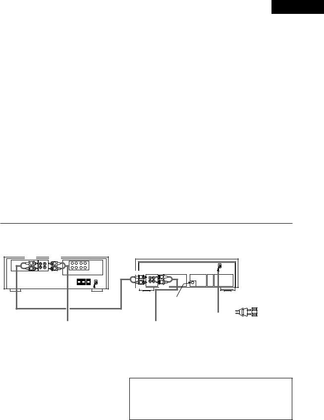
CONNECTION
• Leave your entire system (including this cassette deck) turned off until all connections between the deck and other components have been completed.
Receiver or amplifier |
DRM-555 |
WHITE |
|
WHITE |
|
|
|
L |
PB REC |
L |
|
|
|
L |
|
|
|
||
R |
R |
R |
|
LINE |
|
|
|
WHITE |
|||
|
|
RED |
WHITE |
||
RED |
TAPE-1 |
OUT IN |
|||
|
|
|
L |
L |
L |
|
|
|
R |
R |
R |
|
|
|
LINE LINE |
||
|
|
|
RED |
SYNCHRO |
|
|
|
|
OUT IN |
||
|
|
|
|
RED |
This jack is for the synchronized |
|
|
60 Hz |
|
|||
recording function only. |
|
|
|
||||
Do not plug in microphones, |
|
|
|
|
|
|
|
headphones nor other plugs. |
|
|
|
|
|
|
|
|
|
|
|
|
|
|
|
|
|
|
|
Power supply |
|
|
|
|
outlet. |
2 Connecting the Deck to an Amplifier |
2 Installation Precautions |
|||
• |
Before connecting the deck to your amplifier, please review your |
If the deck is placed near an amplifier, TV or tuner, noise (induced hum) or |
||
|
amplifier’s instruction manual. |
beat interference may result, especially during FM or AM reception. If this |
||
• |
Use the white plugs for the left channel and red plugs for the right |
occurs, place the deck further away from other components or reorient its |
||
|
channel. |
position. |
||
2Tape Dubbing
• Many stereo amplifiers and receivers have tape dubbing circuitry so that
tape duplication can be performed between two or more tape decks. |
Caution: |
|
A mechanical sound is heard the first time the power switch is set to “ON” |
||
Review your amplifier’s instruction manual for a full explanation of this |
||
after the power cord is plugged into an outlet. This is the sound of the |
||
mode of operation. |
||
cassette mechanism being set to the proper operating state, and is normal. |
||
2 Connecting Headphones |
||
(When using an AC outlet on a receiver or amplifier, used an |
||
To listen through headphones, plug your headphones into the PHONES |
||
“UNSWITCHED” outlet.) |
||
jack. |
||
|
5
ENGLISH
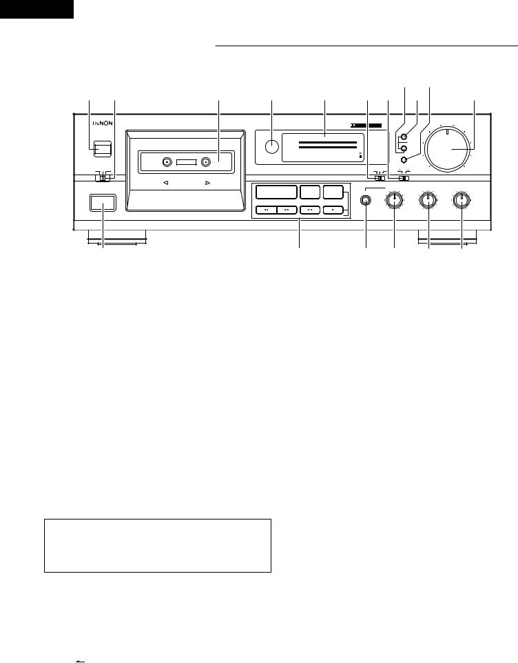
NAMES AND FUNCTIONS OF PARTS
|
o !1 |
w e |
r t y u i !0 !2 |
|
DRM-555 |
|
|
|
|
|
|
|
|
|
|
|
|
|
|
|
|
INPUT LEVEL |
PRECISION AUDIO COMPONENT/CASSETTE TAPE DECK |
|
|
|
|
|
|
|
|
|
|
|
|
|
|
|
|
5 |
|
|
|
|
|
|
|
|
|
|
|
|
|
|
|
|
|
|
4 |
6 |
EJECT |
|
|
|
|
|
|
|
|
|
|
|
|
|
|
|
RESET |
3 |
7 |
5 |
|
|
|
|
|
|
|
|
|
|
|
|
|
|
|
|||
|
dB |
-40 |
-30 |
-20 |
-10 |
-5 |
-3 |
-1 |
0 |
+1 |
+3 |
+5 |
+10 |
|
|
|
|
|
|
L |
|
|
|
|
|
|
|
|
|
|
|
|
|
|
COUNTER |
|
|
|
HIGH SPEED DUBBING SYSTEM |
|
|
|
|
|
|
|
|
|
|
|
|
|
|
|
|
|
|
R |
|
|
|
|
|
|
|
|
|
|
|
|
|
|
MEMORY |
2 |
8 |
|
|
|
|
|
|
|
|
|
|
|
|
|
|
|
|
|||
|
|
|
|
|
|
|
|
|
|
‚¤‚‚ |
|
|
|
|
|
|||
|
|
|
|
|
|
|
|
|
|
|
|
|
|
|
|
MPX |
1 |
9 |
|
|
|
|
|
|
|
|
|
|
|
|
|
|
|
|
|
||
TIMER |
REMOTE SENSOR |
|
|
|
|
|
|
|
|
|
|
|
DOLBY NR |
REV.MODE |
|
|
||
REC OFF PLAY. |
|
|
|
|
|
|
|
|
|
|
|
|
B |
OFF |
C |
|
0 |
10 |
AUTO REVERSE
PHONE LEVEL |
BIAS FINE |
BALANCE |
¢ON £OFF
PLAY |
2 STOP |
3 REC PAUSE |
PHONES |
|
DIRECTION |
REC/REC MUTE |
|
|
|
MIN |
MAX |
- + LEFT RIGHT |
|
|
CD SYNCHRO REC |
|
|
q |
!7 |
!6 !5 |
!4 !3 |
|
q Power Operation Switch (¢ ON £ OFF)
•Press once to turn the power to deck on, and once more to turn the power off.
•The deck remains in a stand-by (non-operative) mode for approximately 2 seconds after it is switched on.
w Eject Button (EJECT 5 )
•Press this button to open the cassette compartment cover. When the tape is running, press the Stop button ( 2 STOP) first to stop tape transport, then press the Eject button (EJECT 5).
e Timer Switch (TIMER)
•This switch is provided for use with an optional audio timer for unattended recording or morning-alarm playback.
•For non-timer operation, this switch should be set in the “OFF” position. See page 14.
r Cassette Compartment Cover
•If the cover is not closed completely, the tape transport buttons will remain inoperative.
t Remote Sensor (REMOTE SENSOR)
•With the cassette deck the remote control unit is not included.
•Each of “Play, Fast Forward, Fast Rewind, Stop, Rec Pause and Rec/Rec Mute” functions can be remote controlled with wireless handset of the receiver (DRA Series receivers). For details refer to the DRA Series operating instructions.
o Counter Memory Button (MEMORY)
•When this button is pressed during forward tape travel (  ), fast rewinding ( 6 ) will stop automatically at the tape counter position “‚‚‚‚”.
•When this button is pressed during reverse tape travel (  ), fast forwarding ( 7 ) will stop automatically at the tape counter position “‚‚‚‚”. See page 13.
!0Counter Reset Button (RESET)
• Press this button to reset the tape counter to zero.
!1MPX Filter Button (MPX)
•The MPX Filter button (MPX) should be used to prevent interference with the Dolby NR circuit when making Dolby NR encoded recordings of FM stereo programs.
•When making Dolby NR encoded recordings from any program source other than FM stereo, leave this button in the “OFF” position.
!2Input Level Control (INPUT LEVEL)
•This knob adjusts the recording input level. It affects the level in both channels. See page 10.
!3Balance Control (BALANCE)
•This is the knob to adjust the recording level balance between the left and right channels. Turn it counter-clockwise to reduce the right channel’s level and clockwise to reduce the left channel’s. Usually, put the knob at the center click position.
Caution:
Whenever the Power Operation switch is in the OFF state, the apparatus is still connected on AC line voltage.
Please be sure to unplug the cord when you leave home for, say, a vacation.
y Display
u Dolby NR Switch (DOLBY NR)
•To record or playback tapes with Dolby B or C-type noise reduction, set this switch to “B” or “C”. Turn it “OFF” when not using the Dolby NR system.
iReverse Mode Switch (REV. MODE)
•Select the type of tape transport. The reverse mode can be set to
 (one side),
  (continuous playback).
!4Bias Fine Control (BIAS FINE)
(For Normal, CrO2 and Metal tape)
•Use this control to fine-adjust the bias. Standard bias is obtained at the center click-stop position. See page 11.
!5Phone Level Control (PHONE LEVEL)
•Head phone output level is adjusted by this knob. The levels in the left and right channels can be changed simultaneously.
!6Headphone Jack (PHONES)
•For private music enjoyment without disturbing others, or for monitoring a recording, a headphone set may be connected to this
jack. Use a headphone with an impedance rating of 8 to 1200 Ω /ohms.
6
ENGLISH
!7Tape Transport Buttons
PLAY |
Play Button |
Press to playback tape. |
|
|
|
|
|
2 STOP |
Stop Button |
Press to stop the tape in any mode. |
|
|
|
|
|
6 |
Fast Rewind Button |
Press for fast rewind. |
|
|
|
|
|
7 |
Fast Forward Button |
Press for fast forwarding. |
|
|
|
|
|
|
|
Press the Rec/Rec Mute button (REC/REC MUTE) ( 4 ) and Play button (PLAY) simultaneously to |
|
4 |
Rec/Rec Mute |
start recording. If only the Rec/Rec Mute button (REC/REC MUTE) ( 4 ) is pressed, the deck enters |
|
Button |
the recording pause mode. Pressing this button in the recording pause mode will start Auto Rec |
||
|
|||
|
|
Mute, and a 5-second silent space is recorded onto the tape. |
|
|
|
|
|
3 REC PAUSE |
Rec Pause Button |
Press this button to enter the recording pause mode from the recording or recording mute mode. |
|
This button can only be used during recording. |
|||
|
|
||
|
|
|
|
0 1 |
Direction Button |
Changes the tape transport direction from forward “1” to reverse “0”, and vice versa. |
|
|
|
|
y Display
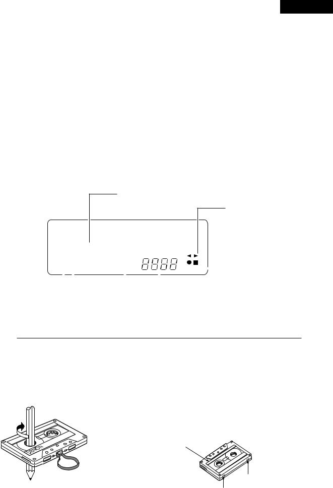
• Indicators with an encircled number light up when the corresponding button is pressed.
Peak Level Meter
Indicates the recording and playback signal levels for the left and right channels.
Tape Transport Indicators
|
|
|
|
|
|
|
|
|
|
|
|
|
|
|
|
|
|
|
|
|
|
|
|
|
|
|
|
|
|
|
|
|
|
|
|
|
|
|
|
|
|
|
|
|
|
|
|
|
|
|
|
|
|
|
|
|
|
|
|
|
dB -40 -30 -20 -10 |
-5 -3 -1 |
0 +1 +3 +5 +10 |
|
|
|
|
|
|
||||||||||||||||||||||||||||||||||||||||||||||||||||
|
L |
|
|
|
|
|
|
|
|
|
|
|
|
|
|
|
|
|
|
|
|
|
|
|
|
|
|
|
|
|
|
|
|
|
|
|
|
|
|
|
|
|
|
|
|
|
|
|
|
|
|
|
|
|
|
|
||||
|
|
|
|
|
|
|
|
|
|
|
|
|
|
|
|
|
|
|
|
|
|
|
|
|
|
|
|
|
|
|
|
|
|
|
|
|
|
|
|
|
|
|
|
|
|
|
|
|||||||||||||
|
|
|
|
|
|
|
|
|
|
|
|
|
|
|
|
|
|
|
|
|
|
|
|
|
|
|
|
|
|
|
|
|
|
|
|
|
|
|
|
|
|
|
|
|
|
|
|
|||||||||||||
|
R |
|
|
|
|
|
|
|
|
|
|
|
|
|
|
|
|
|
|
|
|
|
|
|
|
|
|
|
|
|
|
|
|
|
|
|
|
|
|
|
|
|
|
|
|
|
|
|
|
|
|
|
|
|
|
|
||||
|
|
|
|
|
|
|
|
|
|
|
|
|
|
|
|
|
|
|
|
|
|
|
|
|
|
|
|
|
|
|
|
|
|
|
|
|
|
|
|
|
|
|
|
|
|
|
|
|||||||||||||
|
|
|
|
|
|
|
|
|
|
|
|
|
|
|
|
|
|
|
|
|
|
|
|
|
|
|
|
|
|
|
|
|
|
|
|
|
|
|
|
|
|
|
|
|
|
|
|
|||||||||||||
|
|
|
|
|
MPX |
|
|
SYNC |
|
|
|
|
|
|
|
|
|
|
|
|
|
|
|
|
|
|
|
|
|
|
Memory Indicator |
|||||||||||||||||||||||||||||
|
|
|
|
|
|
|
|
|
|
|
|
|
|
|
|
|
|
|
|
|
|
|
|
|
|
|
|
|
|
|
||||||||||||||||||||||||||||||
|
|
|
|
|
|
|
|
|
|
|
|
|
|
|
|
|
|
|
|
|
|
|
|
|
|
MEMO |
|
|
|
|
||||||||||||||||||||||||||||||
|
|
|
|
|
|
|
|
|
|
|
|
|
|
|
MPX Filter |
|
|
|
|
|
|
|
|
|
|
|
|
|
|
|
|
|
|
|
|
|
|
|
|
Tape Counter |
|
|
||||||||||||||||||
|
|
|
|
|
|
|
|
|
|
|
|
|
|
|
|
|
|
|
|
|
|
|
|
|
|
|
|
|
|
|
|
|
|
|
|
|
|
|
|
|
||||||||||||||||||||
|
|
|
|
|
|
|
|
|
|
|
|
|
|
|
|
|
|
|
|
|
|
|
|
|
|
|
|
|
|
|
|
|
|
|
|
|
|
|
|
|
||||||||||||||||||||
|
|
|
|
|
|
|
|
|
|
|
|
|
|
|
|
|
|
|
|
|
|
|
|
|
|
|
|
|
|
|
|
|
|
|
|
|
|
|
|
|
||||||||||||||||||||
|
|
|
|
|
|
|
|
|
|
|
|
|
|
|
Indicator |
|
|
|
|
|
|
|
|
|
|
|
|
|
|
|
|
|
|
|
|
|
|
|
|
|
|
|
|
|
|
|
|
|
|
|
|
|
|
|||||||
|
|
|
|
|
|
|
|
|
|
Remote |
|
|
|
|
|
|
|
|
|
|
Synchro Rec Indicator (See page 12) |
|
|
|||||||||||||||||||||||||||||||||||||
|
|
|
|
|
|
|
|
|
|
|
|
|
|
|
|
|
|
|
|
|
|
|||||||||||||||||||||||||||||||||||||||
|
|
|
|
|
|
|
|
|
|
Control Indicator |
|
|
|
|
|
|
|
|
|
|
|
|
|
|
|
|
|
|
|
|
|
|
|
|
|
|
|
|
|
|
|
|
|
|
|
|
|
|
||||||||||||
CASSETTE TAPES
2 Handling Precautions
•C-120 cassette tapes
C-120 cassette tapes are not recommended as they use a very thin tape base which may become tangled around the capstan or pinch roller.
•Tape Slack
Before putting a tape into the deck, take up any slack with a pencil or your finger tip. This precaution prevents the tape from becoming entangled around the capstan or pinch roller.
2 Storage Precautions
•Do not store cassette tapes in a place where they will be subject to:
•Extremely high temperature or excessive moisture
•Excessive dust
•Direct sunlight
•Magnetic fields (near TV sets or speakers)
•To eliminate tape slack, store your cassettes in cassette cases with hub stops
2 Accidental Erasure Prevention
•All cassettes have erasure prevention tabs for each side. To protect valuable recordings from accidental or inadvertent erasure, remove the tab for the appropriate side with a screwdriver or another tool.
•To record on a tape whose erasure prevention tabs have been removed, cover the tab holes with adhesive tape.
A
Side A
Erasure prevention tab for side A
Erasure prevention tab for side B
7
 Loading...