


DVD-1600
Table of contents
 Loading...
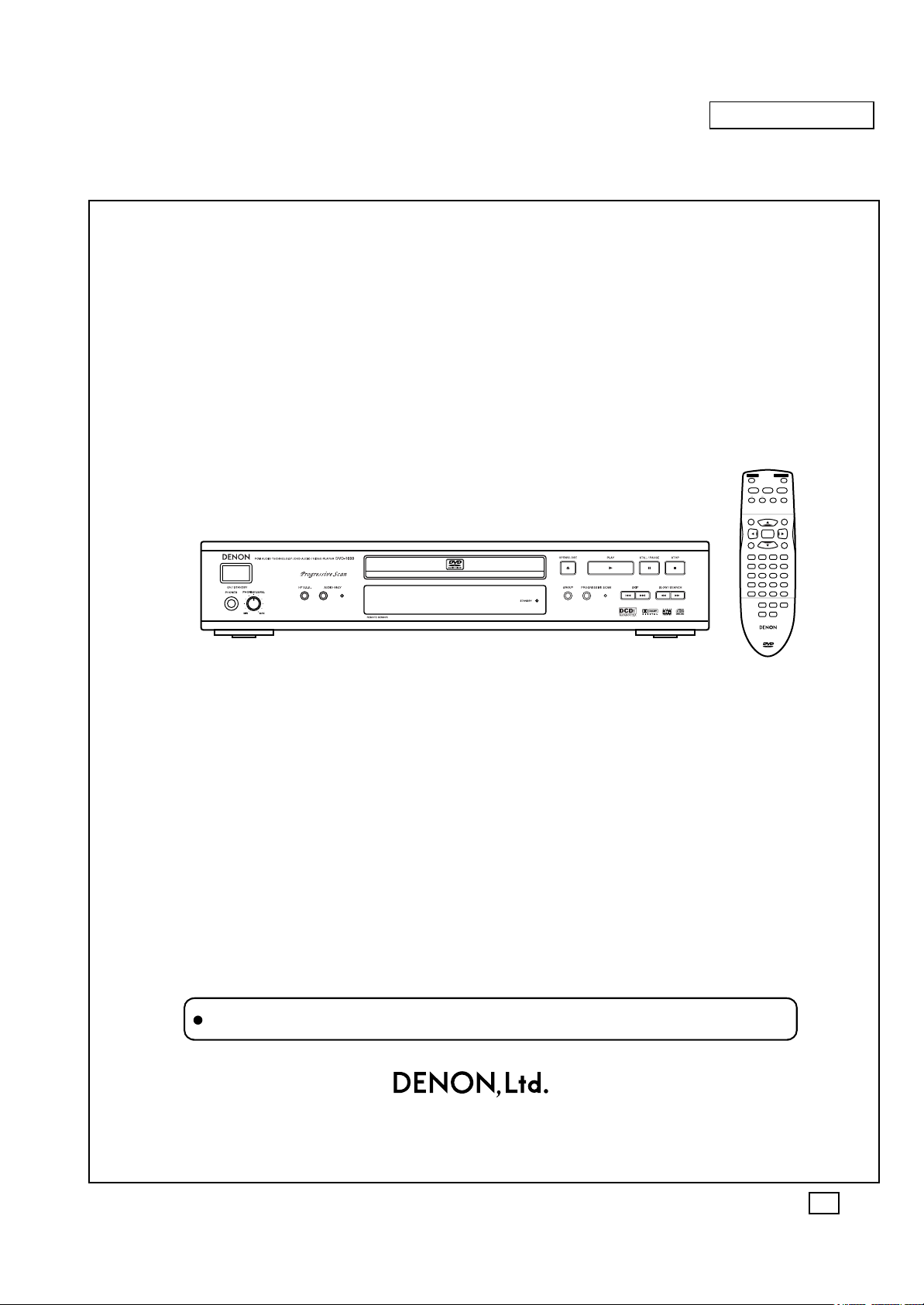
B
SERVICE MANUAL
Some illustrations using in this service manual are slightly different from the actual set.
ENTER
POWER
STOP
STILL / PAUSE
PLAY
OPEN/CLOSE
SKIP
TOP MENU
MENU
DISPLAY
RETURN
GROUP PAGE
AUDIO ONLY
HP-V.S.S. SP-V.S.S.
SLOW / SEARCH
PLAY MODE SUBTITLE
AUDIO ANGLE
123
A-B REPEAT
456
789
SET UP CLEAR
0
10
CINEMA
REPEAT MODE
REMOTE CONTROL UNIT
RC-551
AUDIO
/
VIDEO
MODEL DVD-1600
DVD AUDIO/VIDEO PLAYER
Hi-Fi Personal Component System
For U.S.A. model
X0144 NC 0204
16-11, YUSHIMA 3-CHOME, BUNKYOU-KU, TOKYO 113-0034 JAPAN
Telephone : 03 (3837) 5321

2
Specifications
Operating temperature range: i5 to i35 oC (i41 to i95 oF)
Operating humidity range: 5 to 90 % RH (no condensation)
Discs played [8 cm (3z) or 12 cm (5z)]:
(1) DVD-Video
DVD-R (DVD-Video compatible)
(2) DVD-Audio
(3) CD-Audio (CD-DA)
(4) Video CD
(5) CD-R/CD-RW (CD-DA, Video CD formatted discs)
(6) MP3
≥Maximum number of chapters and titles recognizable:
999 chapters and 511 titles
≥Compatible compression rate: between 32 kbps and
320 kbps
Signal system: NTSC
Video output:
Output level: 1 Vp-p (75 ≠)
Output terminal: Pin jack (2 systems)
S video output:
Y output level: 1 Vp-p (75 ≠)
C output level: 0.286 Vp-p (75 ≠)
Output terminal: S terminal (1 system)
Component video output (480P/480I):
Y output level: 1 Vp-p (75 ≠)
P
B
output level: 0.7 Vp-p (75 ≠)
P
R
output level: 0.7 Vp-p (75 ≠)
Output terminal: Pin jack
(Y: green, P
B
/C
B
: blue,
P
R
/C
R
: red)
Number of terminals: 1 system
Audio output:
Output level: 2 Vrms (1 kHz, 0 dB)
Output terminal: Pin jack
Number of terminals:
2CH: 1 system
5.1ch discrete output (5.1ch): 1 system
Audio performance:
(1) Frequency response:
≥DVD (linear audio): 4 Hz–22 kHz (48 kHz sampling)
4 Hz–44 kHz (96 kHz sampling)
≥DVD-Audio: 4 Hz–88 kHz (
192 kHz sampling
)
≥CD audio: 4 Hz–20 kHz
(2) S/N ratio:
≥CD audio: 115 dB
(3) Dynamic range:
≥DVD (linear audio): 102 dB
≥CD audio: 98 dB
(4) Total harmonic distortion:
≥CD audio: 0.0025 %
Digital audio output:
Optical digital output: Optical terminal
Phones jack: Stereo, 6.3 mm (
1
/
4
q) jack
Pickup: Wave length: 658 nm/790 nm
Laser power: CLASS IIa/CLASS I
Power supply: AC 120 V, 60 Hz
Power consumption: 14 W
Dimensions: 434 (W)k252 (D)k82 (H) mm
[17
1
/
8
q (W)k9
15
/
16
q (D)k3
1
/
4
q (H)]
(including protrusions)
Mass: 2.9 kg (6.4 lb.)
Power consumption in standby mode: approx. 2 W
Note
Specifications are subject to change without notice.
Mass and dimensions are approximate.
3
1.1.1. LEAKAGE CURRENT COLD
CHECK
1. Unplug the AC cord and connect a jumper between the two
prongs on the plug.
2. Measure the resistance value, with an ohmmeter, between
the jumpered AC plug and each exposed metallic cabinet
part on the equipment such as screwheads, connectors,
control shafts, etc. When the exposed metallic part has a
return path to the chassis, the reading should be between
1M: and 5.2M:.
When the exposed metal does not have a return path to
the chassis, the reading must be
.
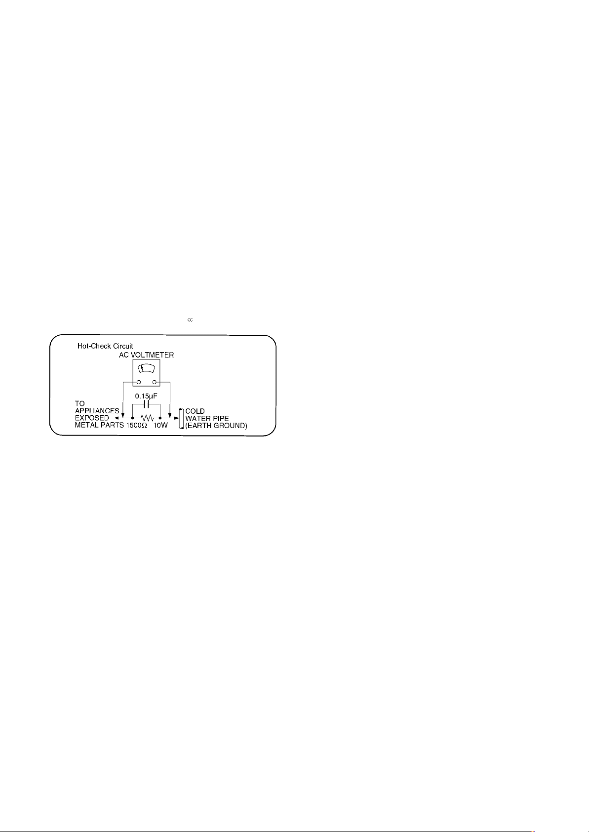
Figure 1
1.1.2. LEAKAGE CURRENT HOT CHECK
(See Figure 1 .)
1. Plug the AC cord directly into the AC outlet. Do not use an
isolation transformer for this check.
2. Connect a 1.5k:,10watts resistor, in parallel with a 0.15µF
capacitors, between each exposed metallic part on the set
and a good earth ground such as a water pipe, as shown in
Figure 1.
3. Use an AC voltmeter, with 1000 ohms/volt or more
sensitivity, to measure the potential across the resistor.
4. Check each exposed metallic part, and measure the
voltage at each point.
5. Reverse the AC plug in the AC outlet and repeat each of the
above measurements.
6. The potential at any point should not exceed 0.75 volts
RMS. A leakage current tester (Simpson Model 229 or
equivalent) may be used to make the hot checks, leakage
current mu3st not exceed 1/2 milliamp. In case a
measurement is outside of the limits specified, there is a
possibility of a shock hazard, and the equipment should be
repaired and rechecked before it is returned to the
customer.
1 SAFETY PRECAUTIONS
1.1. GENERAL GUIDELINES
1. When servicing, observe the original lead dress. If a short circuit is found, replace all parts which have been overheated or
damaged by the short circuit.
2. After servicing, see to it that all the protective devices such as insulation barriers, insulation papers shields are properly
installed.
3. After servicing, make the following leakage current checks to prevent the customer from being exposed to shock hazards.
2 PREVENTION OF ELECTRO STATIC DISCHARGE (ESD)
TO ELECTROSTATICALLY SENSITIVE (ES) DEVICES
Some semiconductor (solid state) devices can be damaged easily by static electricity. Such components commonly are called
Electrostatically Sensitive (ES) Devices. Examples of typical ES devices are integrated circuits and some field-effect transistors and
semiconductor "chip" components. The following techniques should be used to help reduce the incidence of component damage
caused by electro static discharge (ESD).
1. Immediately before handling any semiconductor component or semiconductor-equipped assembly, drain off any ESD on your
body by touching a known earth ground. Alternatively, obtain and wear a commercially available discharging ESD wrist strap,
which should be removed for potential shock reasons prior to applying power to the unit under test.
2. After removing an electrical assembly equipped with ES devices, place the assembly on a conductive surface such as alminum
foil, to prevent electrostatic charge buildup or exposure of the assembly.
3. Use only a grounded-tip soldering iron to solder or unsolder ES devices.
4. Use only an anti-static solder removal device. Some solder removal devices not classified as "anti-static (ESD protected)" can
generate electrical charge sufficient to damage ES devices.
5. Do not use freon-propelled chemicals. These can generate electrical charges sufficient to damage ES devices.
6. Do not remove a replacement ES device from its protective package until immediately before you are ready to install it. (Most
replacement ES devices are packaged with leads electrically shorted together by conductive foam, alminum foil or comparable
conductive material).
7. Immediately before removing the protective material from the leads of a replacement ES device, touch the protective material
to the chassis or circuit assembly into which the device will be installed.
4
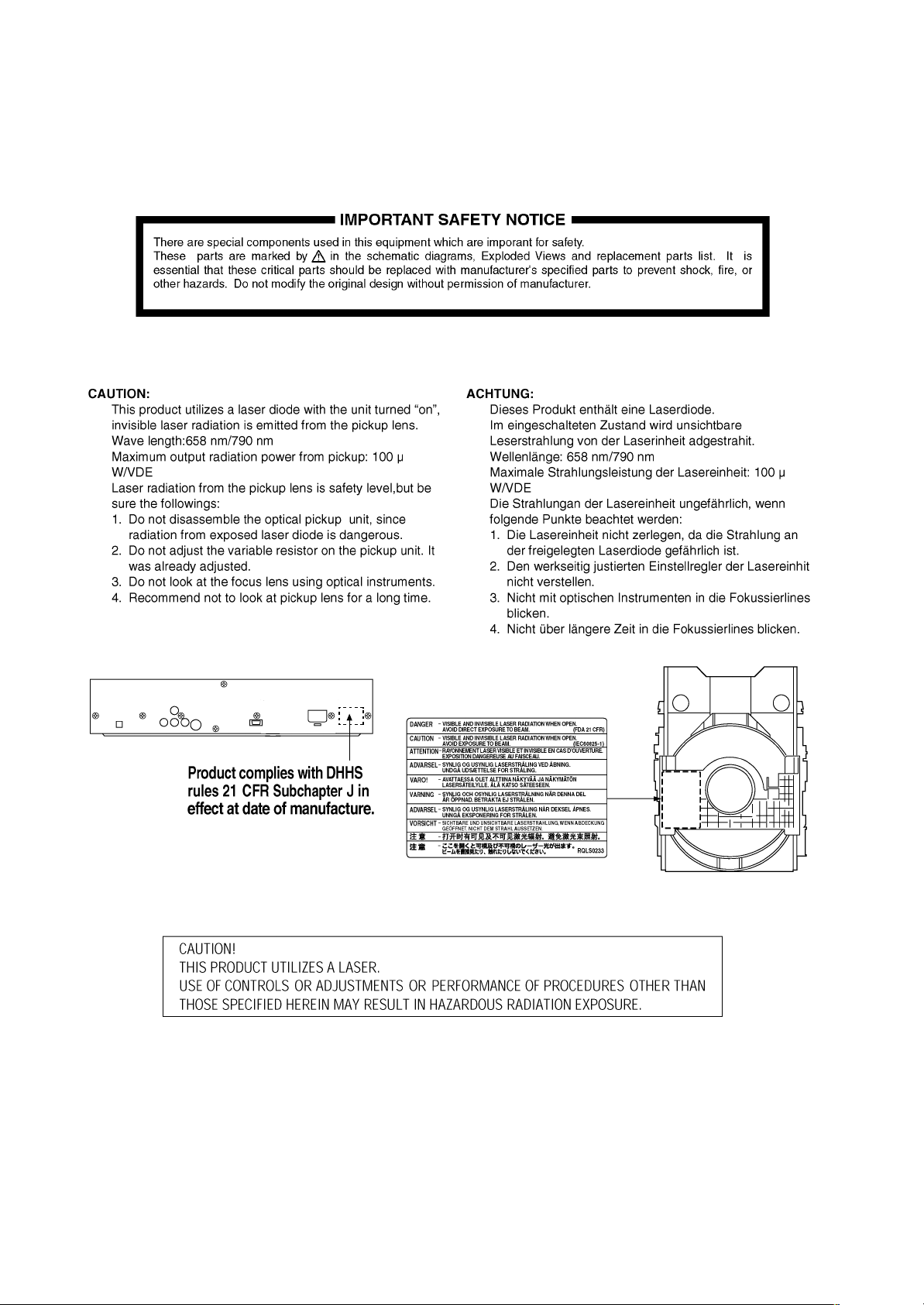
Caution
Be sure no power is applied to the chassis or circuit, and observe all other safety precautions.
8. Minimize bodily motions when handling unpackaged replacement ES devices. (Otherwise hamless motion such as the brushing
together of your clothes fabric or the lifting of your foot from a carpeted floor can generate static electricity (ESD) sufficient to
damage an ES device).
3 Precaution of Lase r Diode

5
4.1. Operating instructions
4 General Description
1 On/standby switch (POWER)
Press to switch the unit from on to standby mode or vice versa.
In standby mode, the unit is still consuming a small amount of
power.
2 Stop button (∫ STOP)
3 Still/Pause button (; STILL/PAUSE)
4 Skip buttons (:, 9 SKIP)
5 Top menu button (TOP MENU)
6 Cursor buttons (3, 4, 2, 1)/Enter button (ENTER)
7 Display button (DISPLAY)
8 Subtitle button (SUBTITLE)
9 Play mode button (PLAY MODE)
: Repeat mode button (REPEAT MODE)
; A-B repeat button (A-B REPEAT)
< Cinema button (CINEMA)
= Setup button (SET UP)
> Clear button (CLEAR)
? Group button (GROUP)
@ Headphone V.S.S. button (HP V.S.S.)
A Open/close button (OPEN/CLOSE)
B Play button (1 PLAY)
C Slow/Search buttons (6, 5 SLOW/SEARCH)
D Menu button (MENU)
E Return button (RETURN)
F Audio button (AUDIO)
G Angle button (ANGLE)
H Numbered buttons (1–9, 0, S10)
I Audio only button (AUDIO ONLY)
J Page button (PAGE)
K Speaker V.S.S. button (SP V.S.S.)
L Audio only indicator
M Disc tray
N Headphone jack (PHONES)
O Headphone level control (PHONES LEVEL)
P Display
Q Standby indicator (STANDBY)
When the unit is connected to the AC mains supply, this indicator
lights up in standby mode and goes out when the unit is turned
on.
R Progressive scan button/indicator
(PROGRESSIVE SCAN)
Buttons such as 2 function the same as the controls on the remote
control.
PCM AUDIO TECHNOLOGY / DVD AUDIO / VIDEO PLAYER DVD-1600
STANDBY
GROUP
OPEN/CLOSE PLAY
SKIP SLOW / SEARCH
STILL / PAUSE STOP
PHONES PHONES LEVEL
HP V.S.S. AUDIO ONLY
MIN MAX
AUDIO
/
VIDEO
ON / STANDBY
REMOTE SENSOR
1
N
O P Q ? R 4 C
@
M A B 3 2IL
PROGRESSIVE SCAN
ENTER
POWER
STOP
STILL / PAUSE
PLAY
OPEN/CLOSE
SKIP
TOP MENU
MENU
DISPLAY
RETURN
GROUP PAGE
AUDIO ONLY
HP V.S.S. SP V.S.S.
6:9 5
∫;
SLOW / SEARCH
PLAY MODE SUBTITLE
AUDIO ANGLE
123
A-B REPEAT
456
789
SET UP
CLEAR
0
S
10
CINEMA
REPEAT MODE
1
REMOTE CONTROL UNIT
RC-551
AUDIO
/
VIDEO
1A
B
D
G
H
I
J
K
E
F
C
4
@
2
5
6
9
:
;
<
=
7
>
?
8
3
6
5Disassembling the Casing and Checking P.C.B.s
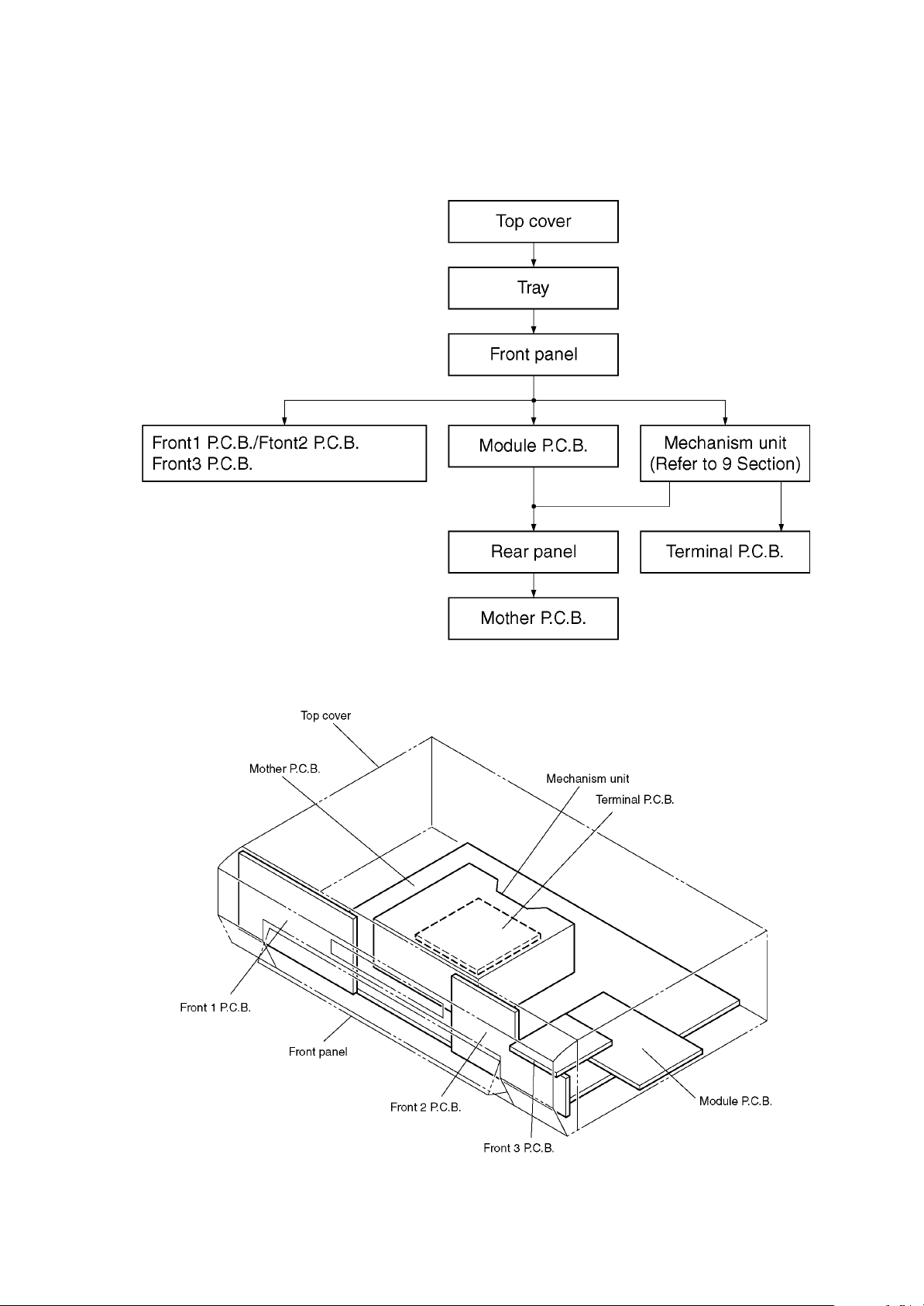
5.1. Dissasembly Procedure
5.2. Caseing Parts and P.C.B. Positions
7
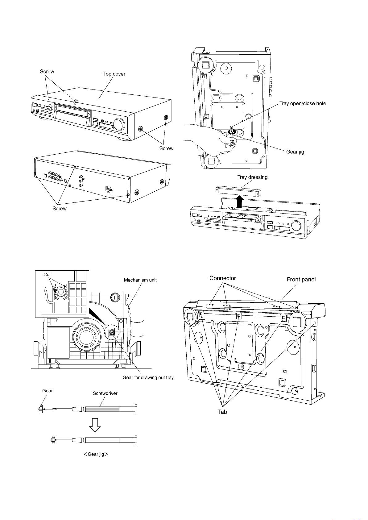
5.3. Top Cover
1. Unscrew the screws.
5.4. Tray
1. Pull the tray out of the mechanism unit. Remove the gear
and install it onto a screwdriver to make a gear jig.
2. Insert the gear jig into the tray open/close hole.
3. Turn the gear jig counterclockwise to open the tray.
4. Remove the tray dressing from the tray section.
5.5. Front Panel
1. Release the tabs.
2. Remove the connectors.
8
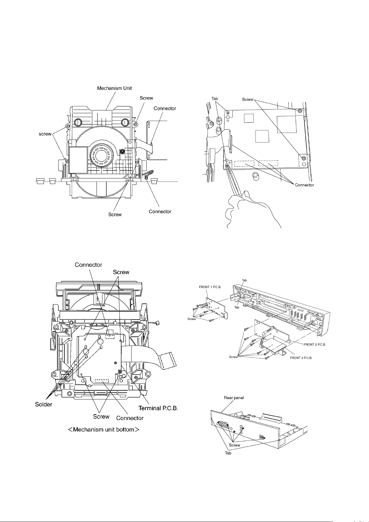
5.6. Mechanism Unit
1. Unscrew the screws.
2. Remove the connectors.
3. Pull out the mechanism unit vertically.
5.7. Terminal P.C.B.
1. Unscrew the screws.
2. Remove the solders.
3. Remove the connectors.
5.8. Module P.C.B.
1. Unscrew the screws.
2. Remove the connectors.
3. Press each tab with the nipper to pull out the module PCB
vertically.
5.9. Front-1 P.C.B., Front-2 P.C.B.,
and Front-3 P.C.B.
1. Unscrew the screws.
2. Release the tabs.
5.10. Rear panel
1. Unscrew the screws
2. Release the tabs.
9
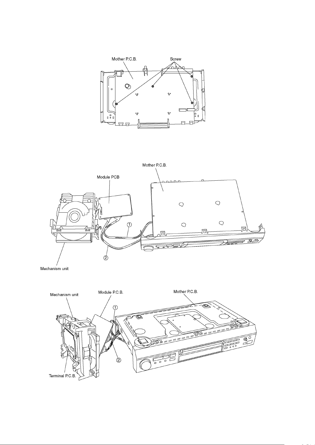
5.11. Mother P.C.B.
1. Unscrew the screws.
5.12. Servicing Position
5.12.1. Servicing position of the Module P.C.B.
5.12.2. Servicing position of the Terminal P.C.B.

10
5.12.3. List of the Extention Cables
11
5.13.3. List of the Extention Cables
6 PREVENTION OF STATIC ELECTRICITY DISCHARGE
The laser diode in the traverse unit (optical pickup) may brake down due to static electricity of clothes or human body. Use due
caution to electrostatic breakdown when servicing and handling the laser diode.
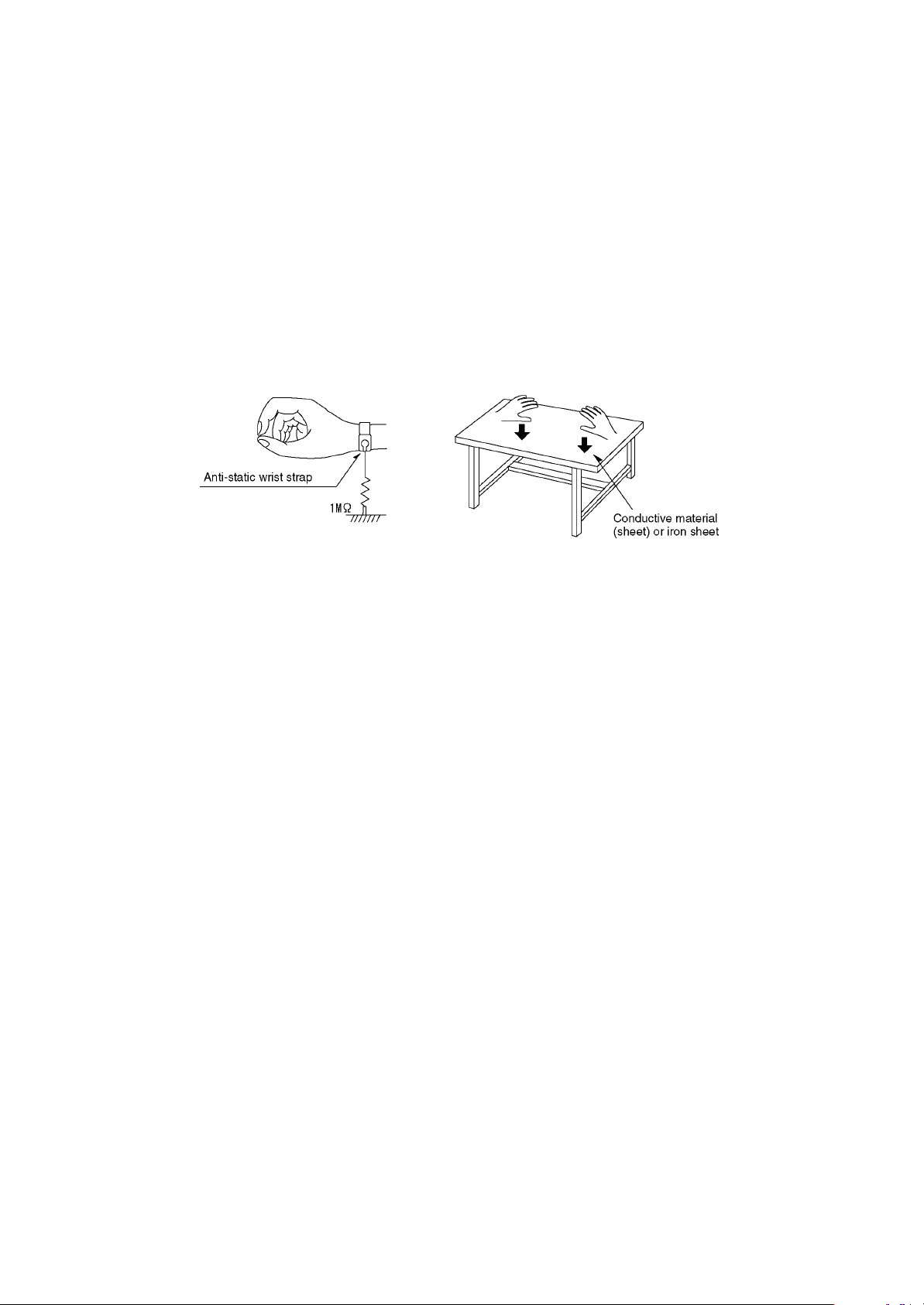
6.1. Grounding for electrostatic breakdown prevention
Some devices such as the DVD player use the optical pickup (laser diode) and the optical pickup will be damaged by static
electricity in the working environment. Proceed servicing works under the working environment where grounding works is
completed.
6.1.1. Worktable grounding
1. Put a conductive material (sheet) or iron sheet on the area where the optical pickup is placed, and ground the sheet.
6.1.2. Human body grounding
1. Use the anti-static wrist strap to discharge the static electricity form your body.
6.1.3. Handling of optical pickup
1. To keep the good quality of the optical pickup maintenance parts during transportation and before installation, the both ends of
the laser diode are short-circuited. After replacing the parts with new ones, remove the short circuit according to the correct
procedure. (See this Technical Guide.)
2. Do not use a tester to check the laser diode for the optical pickup. Failure to do so will damage the laser diode due to the power
supply in the tester.
6.2. Handling Precautions for Traverse Unit (Optical Pickup)
1. Do not give a considerable shock to the traverse unit (optical pickup) as it has an extremely high-precise structure.
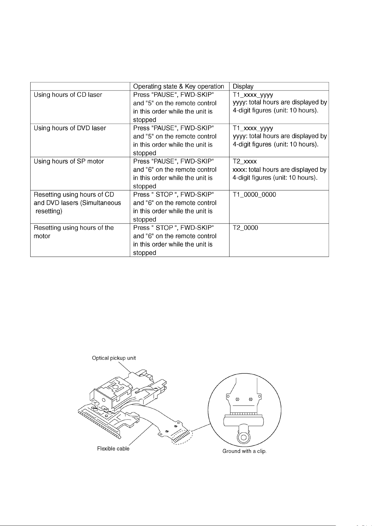
2. When replacing the optical pickup, install the flexible cable and cut its short land with a nipper. See the optical pickup
replacement procedure in this Technical Guide. Before replacing the traverse unit, remove the short pin for preventing static
electricity and install a new unit. Connect the connector as short times as possible.
3. The flexible cable may be cut off if an excessive force is applied to it. Use caution when handling the cable.
4. The half-fixed resistor for laser power adjustment cannot be adjusted. Do not turn the resistor.

12
7 OPTICAL PICKUP SELF-DIAGNOSIS AND
REPLACEMENT PROCEDURE
7.1. Self-diagnosis
The optical pickup self-diagnosis function and tilt adjustment check function have been included in this unit. When repairing, use
the following procedure for effective Self-diagnosis and tilt adjustment.Be sure to use the self-diagnosis function before replacing
the optical pickup when "NO DISC" is displayed. As a guideline, you should replace the optical pickup when the value of the laser
drive current is more than 55.
Note:
Press the power button to turn on the power, and check the value within three minutes before the unit warms up. (Otherwise,
the result will be incorrect.)
13
Cautions to be taken when replacing the optical pickup
The optical pickup may break down due to the static
electricity of human body. Take proper protection measures
against static electricity before repairing the parts around
the optical pickup. (See the page describing the
PREVENTION OF STATIC ELECTRICITY DISCHARGE.)
1. Do not touch the areas around the laser diode and
actuator.
2. Do not judge the laser diode with a tester. (The tester
will be damaged easily.)
3. It is recommended to use a destaticized soldering iron
for short-circuiting or removing the laser diode.
(Recommended soldering iron) HAKKO ESD Product
4. Solder the land of the flexible cable in the optical pickup.
Note:
x
xx
xWhen using a soldering iron which is not
destaticized, short-circuit the terminal face of the
flexible case with a clip. After that, short-circuit
the land.
x
xx
xAfter the repairing work is completed, remove the
solder according to the correct procedure shown
in this Technical Guide.
7.2. Cautions to Be Used Before Replacing the Optical Pickup Unit and
Spindle Motor Assembly
Before replacing the optical pickup unit and spindle motor assembly, check the total using hours for each of them. The checking
method is as follows:

14
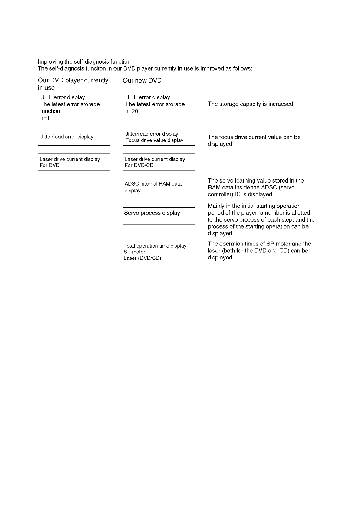
8.1.2. New self-diagnosis function
8 Self-Diagnosis Function and Service Modes
8.1. New servicing method for DVD player (5th generation models)
With the 5th generation models new self-diagnosis function and new servicing method described below are additionally
available.
8.1.1. Firmware updating and recovery with disc
x
xx
xRecovery
x
xx
xFirmware updating
Simply run the recovery disc. Then both of the above operations are automatically performed.
Commercially available CD-R can now perform updating and recovery process, making it easier to update the version.
Recovery process: Optimization of player after replacement of FROM, EEPROM and modular P.C.B.
Version updating: Firmware updating for improved operability and performance
x
xx
xCumulative operation time display function (Spindle motor and DVD/CD laser)
x
xx
xServo process display function
x
xx
xADSC internal RAM display function
x
xx
xOther: Increased number of last errors storage
1event o20 events
Utilization of the above functions, in combination with servicing procedures, is expected to contribute to higher efficiency of fault
diagnosis.
[Purposes]
Operation time display function: For faultfinding of spindle motor or laser that has limited service life
Servo process display: For fault diagnosis of player startup malfunction
ADSC internal RAM display function: For faulty part identification in servo system using the learned values

15
8.2.2. Updating firmware
8.2. How to use recovery disc
8.2.1. Performing recovery
1. Load the recovery disc RFKZD5TR007 on to the player and run it.
2. Recovery is performed automatically. When it is finished, a message appears on the screen.
3. Remove the recovery disc.
4. Turn off the power.
1. Load the recovery disc RFKZD5TR007 on to the player and run it.
2. Firmware version of the player is automatically checked. Appropriate message appears whenever necessary.
3. Using remote controller´s cursor key, select whether version updating is to be done or not. (Selection of Yes/No)
4. a. If Yes is selected, version updating is performed.
b. If No is selected, only recovery is performed.
5. a. When updating is finished, remove the disc according to the message appearing on the screen.
b. Remove the disc according to the message appearing on the screen.
6. Turn off the power.
16
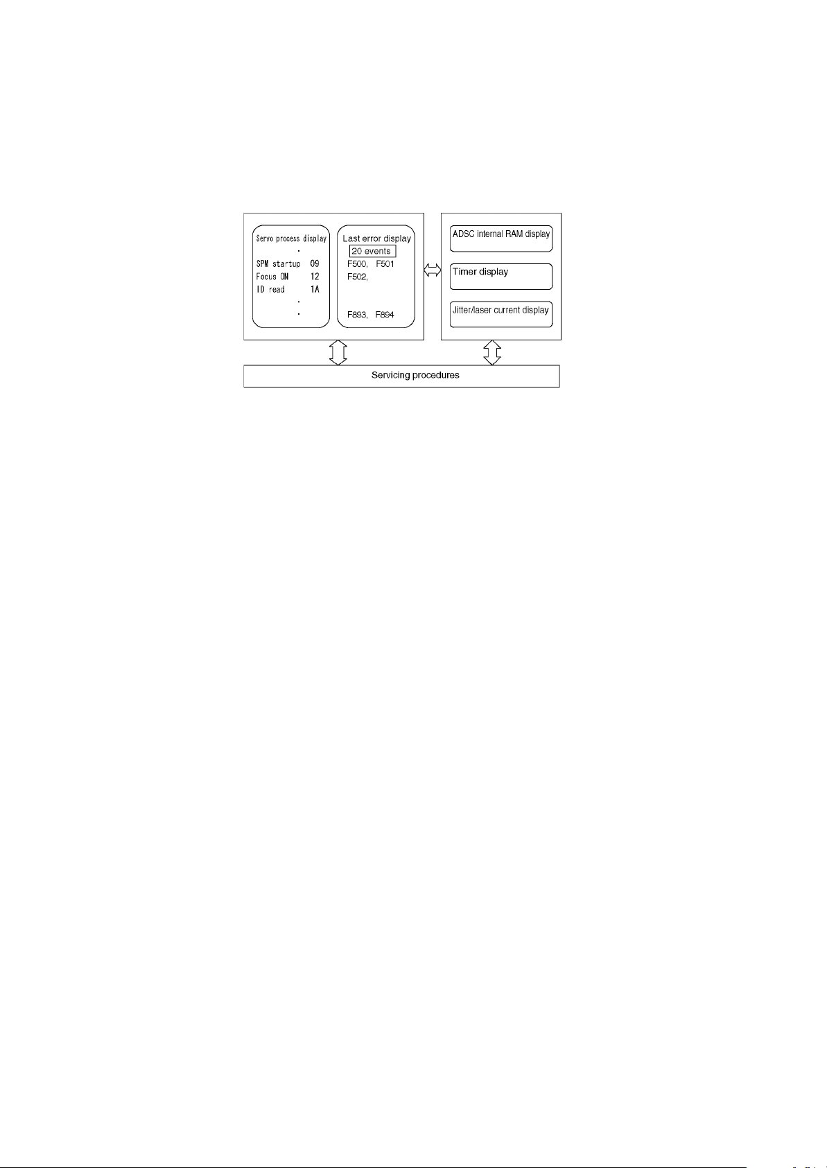
8.3. Fault diagnosis using new self-diagnosis function
The 5th generation DVD players have the additional new service modes as described above to further reinforce the diagnosis
function.
These new functions are unable to bring sufficient results when they are used alone.
Effective fault diagnosis can be expected when multiple diagnostic methods are properly combined in accordance with the servicing
procedures depending on specific fault status.
* New servicing procedures are now under study to match with the newly developed self-diagnosis functions introduced here.
Details of the new servicing procedures will be informed from time to time.
1. Cumulative operation time display function
For spindle motor and DVD/CD laser, the cumulative operation time is displayed.
When servicing, check the timer display and use it as information for fault diagnosis.
At the time of repair and replacement of these components, make sure to check the operation time and reset the timer after
replacement.
Operation time of the replacement parts (spindle motor and laser) is the valuable information as actual data for future product
quality.
Please save the records and supply information to us.
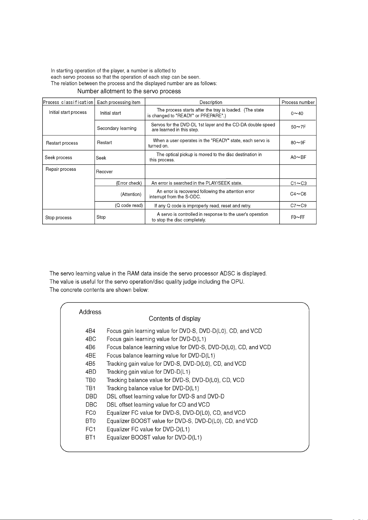
2. Servo process display function
This additional function is intended to improve efficiency of fault diagnosis, especially for the player´s startup failure, in
combination with the learned value data of ADSC internal RAM.
3. ADSC internal RAM display function
The function is to display the internal RAM data of ADSC servo processor.
The RAM data are the learned values of drive servo, memorizing those concerning focus and tracking, as well as data slice and
equalizer.
* This function is also a newly developed service mode. Its full utilization is still under study.
4. Others
x
xx
xIncreased number of last errors stored
1event o20 events
Focus drive value display function

17
8.4.1. Cumulative operation time display
8.4.2. Servo process display
8.4. Overview of each function
1. Operation/display
Key operations are as follows.
Laser operation time ............. In STOP mode, main unit PAUSE+FWD-SKIP+ remote controller [5]
Spindle motor operation time ..... In STOP mode, main unit PAUSE+FWD-SKIP+ remote controller [6]
To reset the timer, perform the following while displaying the time with above key operation.
Laser operation time ............. In STOP mode, main unit STOP+FWD-SKIP+ remote controller [5]
Spindle motor operation time ..... In STOP mode, main unit STOP+FWD-SKIP+ remote controller [6]
2. How to utilize
Reference information in fault diagnosis of laser or spindle motor system
Review of faulty point in repeated repair
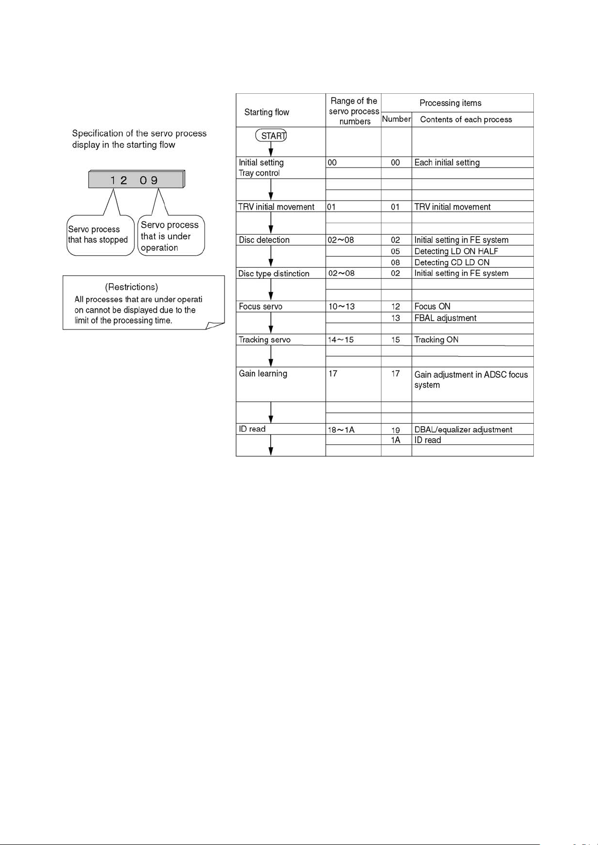
1. Operation/display
While the player is in STOP mode, perform the specified key operation to display the servo process number on FL.
When the display does not change from the error indication, press Open/Close key to show the servo process number.
Key operation: In STOP mode, main unit PAUSE+FWD- SKIP+ remote controller [7]
18
8.4.3. ADSC internal RAM display function
1. Operation/display
Key operation: Main unit PAUSE+OPEN + remote controller [RETURN] Operate the remote controller [CLEAR] key to update
internal RAM address and display 11 learned values.
Table 1 shows the descriptions of the display.
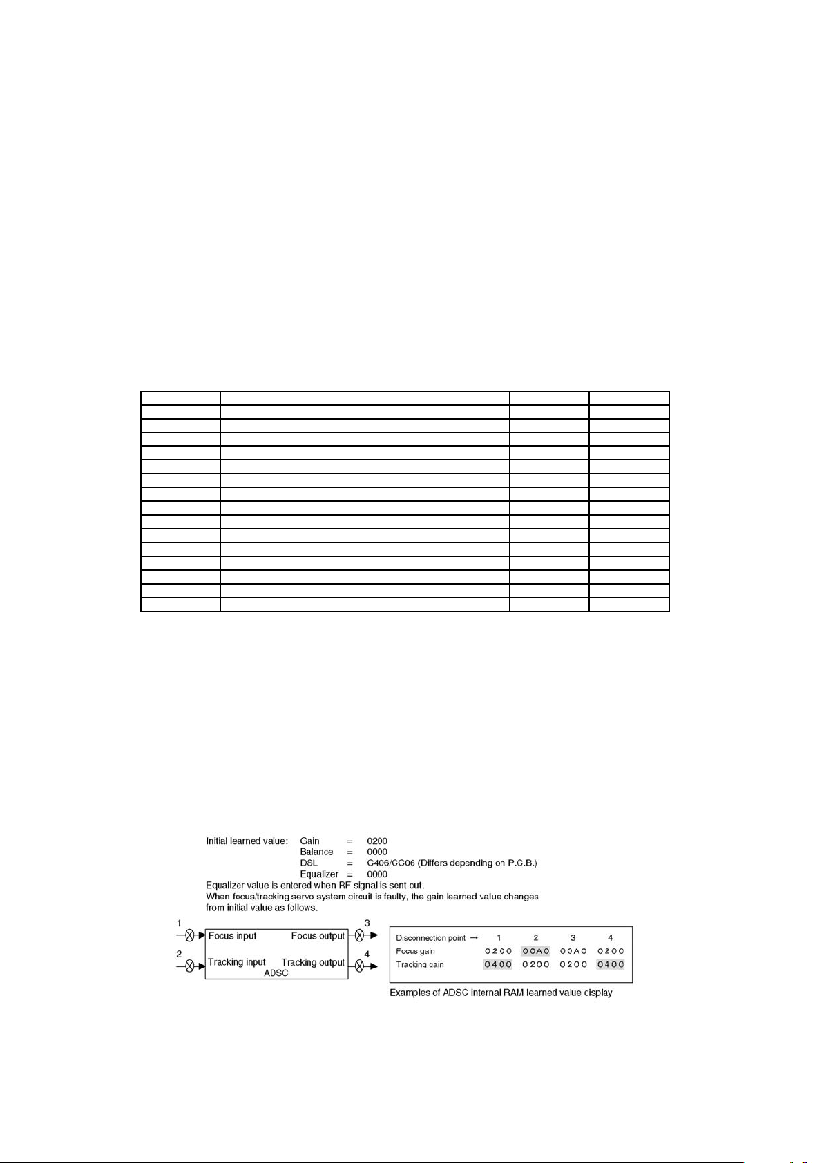
2. How to utilize
At present, learned values of ADSC internal RAM are expected to be useful for the following faulty part identification.
Use how learned value changes from initial value to find whether faulty part exists before or after ADSC in the focus/tracking
servo system.
[Focus system]
When focus gain remains at initial value and tracking gain changes, fault exists before ADSC input.
When focus gain changes and tracking gain remains at initial value, fault exists after ADSC output.
[Tracking system]
When focus gain remains at initial value and tracking gain changes, fault exists after ADSC output.
When focus gain changes and tracking gain remains at initial value, fault exists before ADSC input.
Table 1 ADSC internal RAM learned value
Address Memory data Data range Standard value
4B4 Focus gain learned value except for DVD DL (L1 layer) 0040h~0800h 200h
4BC Focus gain learned value of DVD DL (L1 layer) 0040h~0800h 200h
4B6 Focus balance learned value except for DVD DL (L1 layer) B000h~5000h 0000h
4BE Focus balance learned value of DVD DL (L1 layer) B000h~5000h 0000h
4B5 Tracking gain learned value except for DVD DL (L1 layer) 0040h~0800h 200h
4BD Tracking gain learned value of DVD DL (L1 layer) 0040h~0800h 200h
TB0 Tracking balance learned value of DVD SL and DL (L0) 0060h~FFA0h 0000h
Tracking balance learned value of CD and VCD B000h~5000h 0000h
TB1 Tracking balance learned value of DVD DL (L1 layer) FFA0~0060h 0000h
DBD DSL offset learned value of DVD 9000h~F000h
DBC DSL offset learned value of CD and VCD 9000h~F000h
FC0 Equalizer FC value except for DVD DL (L1 layer) 0000h~0004h
BT0 Equalizer BOOST value except for DVD DL (L1 layer) 0000h~0004h
FC1 Equalizer FC value of DVD DL (L1 layer) 0000h~0004h
BT1 Equalizer BOOST value of DVD DL (L1 layer) 0000h~0004h
Notes:
1. Learned values of focus balance and tracking balance are the coded binary data.
2. DSL offset learned value is effective only in upper 2 digits. (Lower 2 digits, normally 06, are ignored.)
Picking up servo learned value (Determined)
1. Focus (primary)/tracking balance learning ... When leading in focus
2. Focus/tracking gain and equalizer ... When leading in tracking
3. Focus balance (secondary) ... When leading in tacking
[Note]
When fault exists somewhere after tracking servo, the disc type is switched by retry to make learned value different from the
one in normal startup.
19
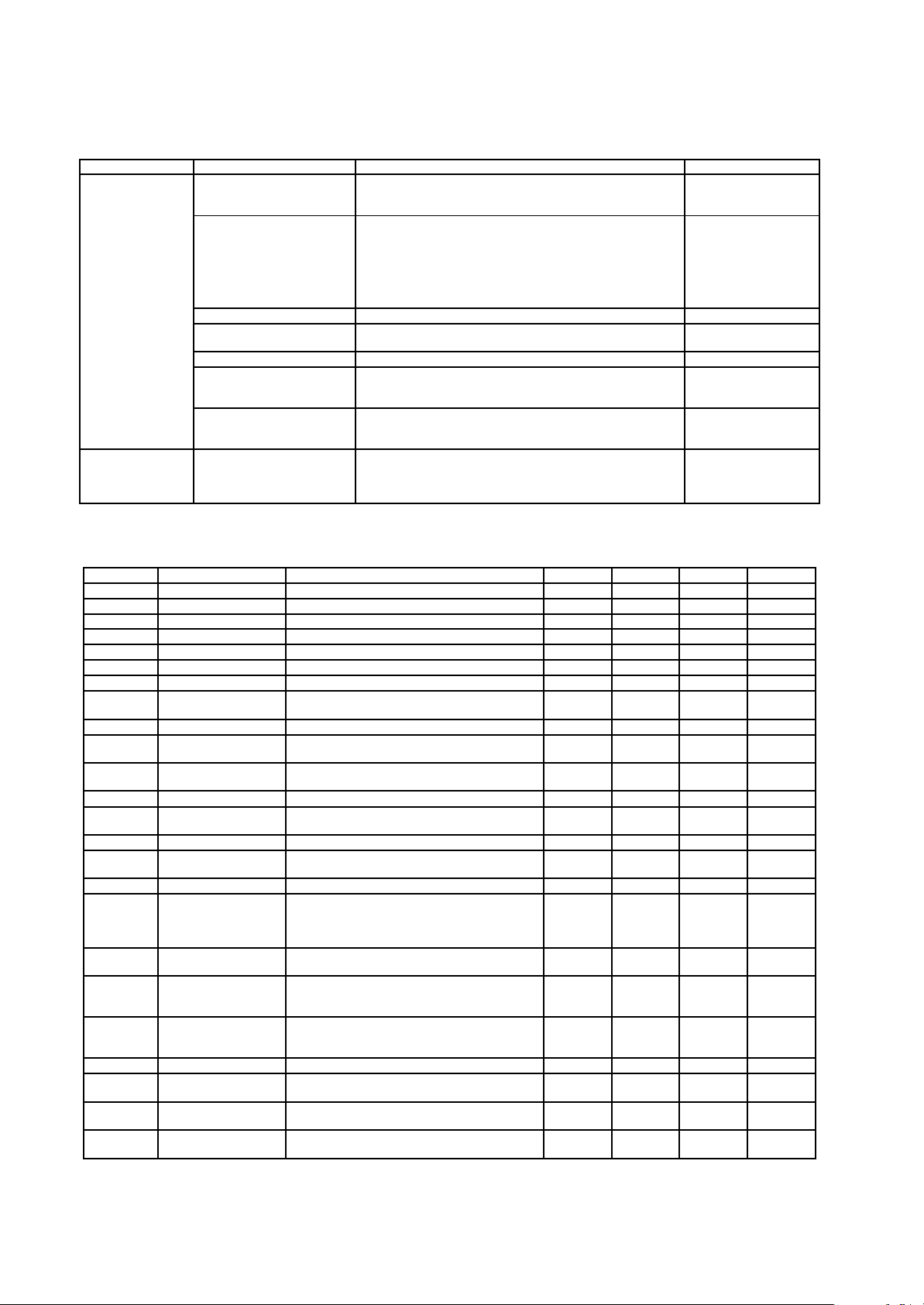
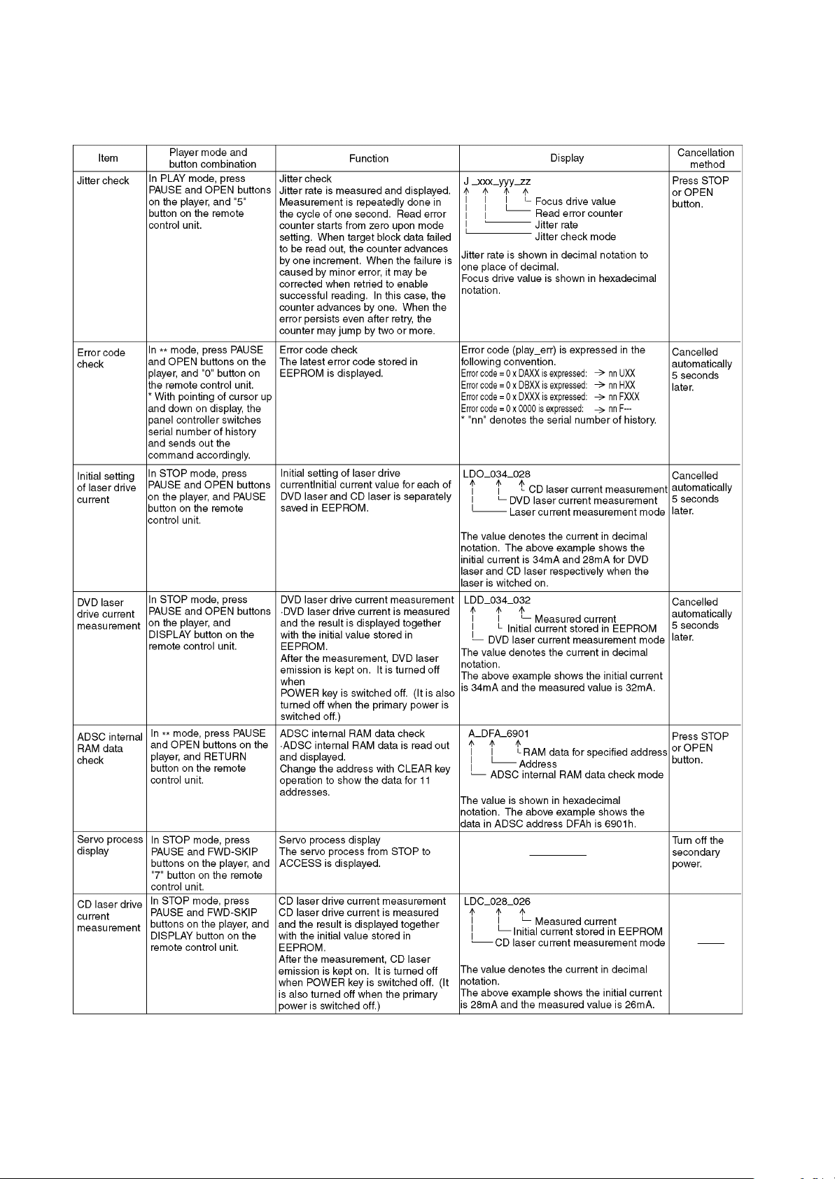
8.5. Service Mode Table 1
The service modes can be activated by pressing various button combination on the player and remote control unit.
Player buttons Remote control unit buttons Application Note
PAUSE
+
OPEN/CLOSE
0 Displaying the UHF display F_ _ _ Refer to section 8.5. Self-
Diagnosis Function (UHF
Display).
5 Jitter check, tilt adjustment
*Display shows J_xxx_yyy_zz
"yyy" and "zz" shown to the right have nothing to do with the jitter
value. "yyy" is the error counter, while "zz" is the focus drive
value.
Refer to section 10.4. for Optical Pickup Tilt Adjustment
Procedure.
Refer to section 10.4.
Optical Pickup Tilt
Adjustment
6 Checking the region numbers and broadcast system
7 Checking the program version Check the IC6302 FLASH
ROM program.
9 Lighting Confirmation Function of Display Tube
DISPLAY Checking the laser drive current Refer to section 9 Optical
Pickup Replacement
Procedure.
PAUSE Writing the laser drive current value after replacing the optical
pickup (do not use for anything other than optical pickup
replacement)
PAUSE
SKIP/SEARCH<<
OPEN/CLOSE
Initializing the DVD player
(restoring factory preset settings)
*Use when replacing a microprocessor, microprocessor
peripheral, or P.C.B.
Refer to section 8.2.
Initializing the DVD
player.
8.6. DVD Self Diagnostic Function-Error Code
Error Code Error Content Additional error explanation Defect 1 Defect 2 Defect 3 Defect 4
U, H error
U11 Focus error
H01 Tray loading error
H02 Spindle servo error (Spindle servo, DSC SP motor, CLV servo error)
H03 Traverse servo error
H04 Tracking servo error
H05 Seek error
H06 Power error Cannot switch off the power because of the panel
and system computer communication error
DSC related
F500 DSC error DSC stops in the occurence of servo error (starup,
focus error, etc)
OPU ADSC FEP servo drive
F501 DSC not Ready DSC-system computer communication error
(Communication failure caused by idling of DSC)
ADSC CPU
F502 DSC Time out error Similar disposal as F500 OPU ADSC FEP servo drive
F503 DSC communication
Failure
Communication error (result error occured
although communication command was sent)
ADSC FEP EEPROM
F505 DSC Attention error Similar disposal as F500 OPU ADSC FEP servo drive
F506 Invalid media Disc is flipped over, TOC unreadable,
incompatible disc
DISC FEP ADSC ODC
ODC related
F600 Access failure to
management
information caused by
demodulation error
Operation stopped because navigation data is not
accessible caused by the demodulation defect
ODC FEP ADSC
F601 Indeterminate sector ID
requested
Operation stopped caused by the request to
access abnormal ID data
ODC FEP ADSC
F602 Access failure to LEAD-
IN caused by
demodulation error
LEAD IN data unreadable
F603 Access failure to
KEYDET caused by
demodulation error
Access failure to CSS data of disc
F610 ODC abnormality No permission for command execution ODC
F611 6626 QCODE don’t
read Error
Access failure to seek address in CD series ODC
F612 No CRC OK for a
specific time
Access failure to ID data in DVD series ODC
F630 No reply to KEY DET
enquiry
(for internal use only)

20
Error Code Error Content Additional error explanation Defect 1 Defect 2 Defect 3 Defect 4
F631 CPPM KEY DET is not
available till the FILE
terminal
(CPPM file system is unreadable caused by
scratches)
DISC CPPM
F632 CPPM KEY DET is not
available
Been revoked or falsified DISC EEPROM CPPM
Disc code
F103 Illegal highlight Position Big possibility of disc specification violation during
highlight display
DISC
HIC Error
F4FF Force initialize failure
(time out)
EEPROM CPU FEP ADSC
Micro computer error
F700 MBX overflow When replying message to disc manager
F701 Message command
does not end
Next message is sent before replying to disc
manager
F702 Message command
changes
Message is changed before it is sent as a reply to
disc manager
F880 Task number is not
appropriate
Message coming from a non-existing task
F890 Sending message when
message is being sent
to AV task
Sending message to AV task
F891 Message couldn’t be
sent to AV task
Begin sending message to AV task
F893 FROM falsification FROM CPU
F894 EEPROM abnormality EEPROM Serial
communicat
ion on lone
F8A0 Message command is
not appropriate
Begin sending message to AV task
8.7. Last Error Code saved during NO PLAY
Error code Error Content System computer Setting task System computer internal error code
F0BF 6) Cannot playback because
physical layer is not recoginizable
PCND_NOPLAY PHYSICAL
0x50
DriveManager 0xDOBF
F0C0 8) DVD: Cannot playback because it
is not DVD Video/Adio/VR
PCND_NOPLAY VIDEO 0x70 DiscManager 0xDOC0
F0C1 9) DVD: Prohibited by the restricted
region code
PCND_NOPLAY RCD 0x80 DiscManager 0xDOC1
F0C2 A) DVD: PAL restricted playback PCND_NOPLAY PAL 0x90 DiscManager 0xDOC2
F0C3 B) DVD: Parental lock setting
prohibits the playback of the entire
title
PCND_NOPLAY PTL 0xA0 DiscManager 0xDOC3
F0C4 C) VCD: Prohibited because it is in
PHOTO CD fromat
PCND_NOPLAY PHOTO CD
0xB0
DiscManager 0xDOC4
F0C5 VCD/CD: Prohibited because it is
CDROM without CD-DA
PCND_NOPLAY CDROM 0xC0 DiscManager 0xDOC5
21
8.8. Self-diagnosis Function and Service Modes
22
8.9. Service mode table 2
Pressing various button combinations on the player and remote control unit can activate the service modes.
23
24
8.10. Servo Process Flow
25
8.11. Servo Process Display Mode
8.12. ADSC Internal Ram Data Display
26
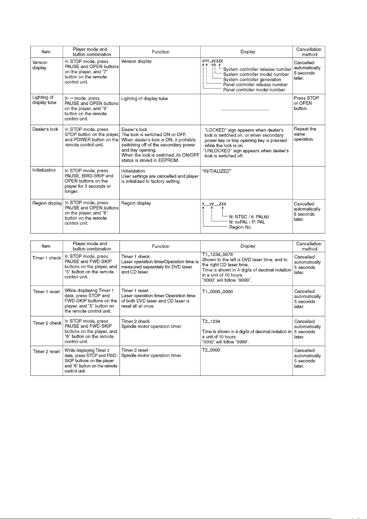
8.13. Sales demonstration lock function
This function prevents discs from being lost when the unit is used for sales demonstrations by disabling the disc eject function.
"LOCKED" is displayed on the unit, and ordinary operation is disabled.
8.13.1. Setting
The sales demonstration lock is set by simultaneously pressing STOP button on the player and POWER button on the remote
control unit.
8.13.2. Cancellation
The lock can be cancelled by the same procedure as used in setting. ("UNLOCKED" is displayed on cancellation. Disconnecting
the power cable from power outlet does not cancel the lock.)
8.14. Service Precautions
8.14.1. Recovery after the dvd player is repaired
8.14.2. Firmware version-up of the DVD player
8.15. Handling After Completing Repairs
Use the following procedure after completing repairs.
8.15.1. Method
Confirm that the power is turned on:
1. Press the "OPEN/CL OSE" button to close the tray.
2. Press the "POWER" button to turn off the power.
3. Disconnect the power plug from the outlet.
8.15.2. Precautions
Do not disconnect the power plug from the outlet with the tray still open, then close the tray manually.
9
27
9 ASSEMBLING AND
DISASSEMBLING THE
MECHANISM UNIT
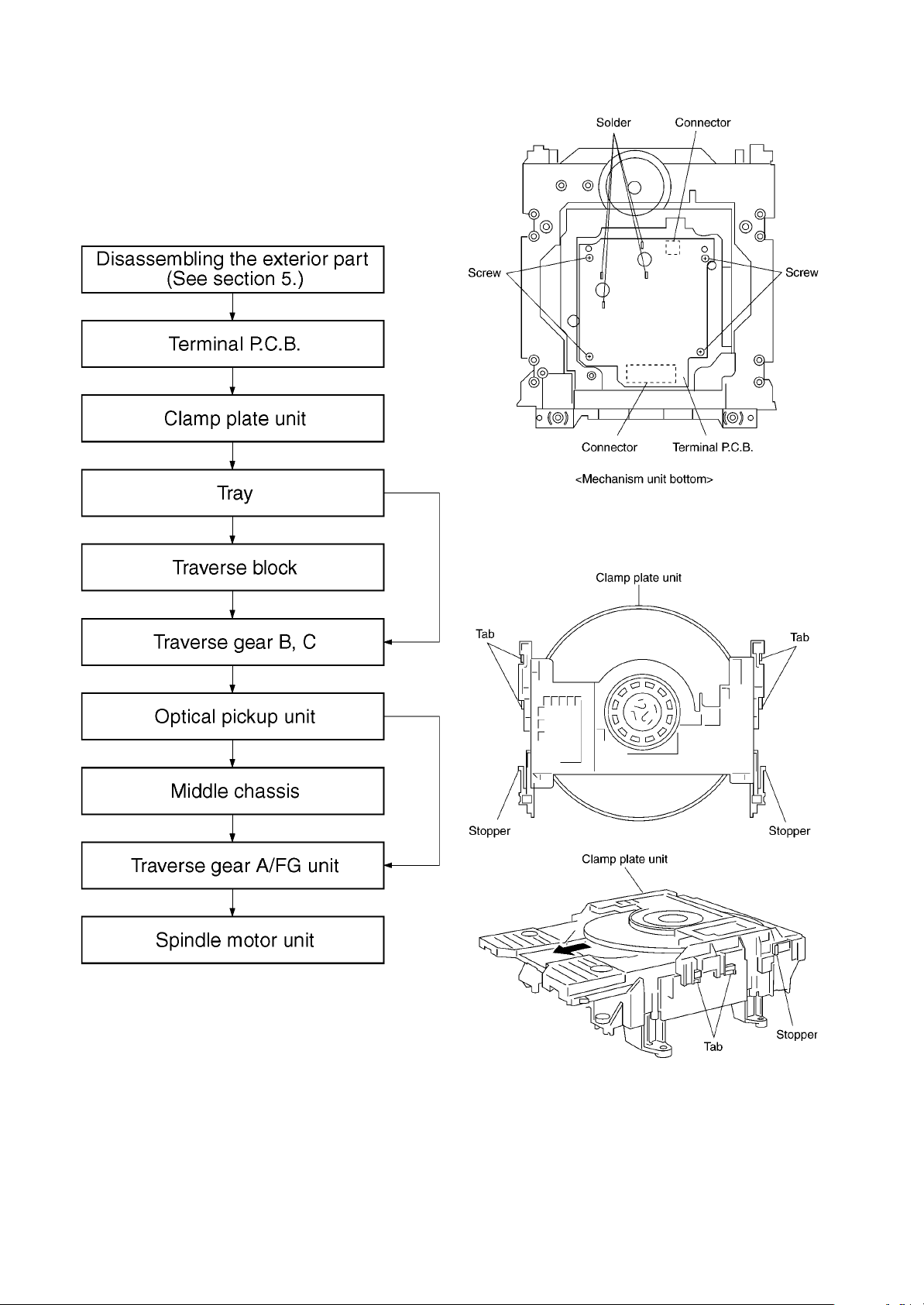
9.1. Disassembly Procedure
9.2. Terminal P.C.B.
1. Unscrew the screws.
2. Remove the solders.
3. Remove the connectors.
9.3. Clamp Plate Unit
1. Spread the stopper with hand to slide the tabs and remove
the clamp plate unit.

28
9.4. Tray
1. Lift the tray.
OReassemble the tray so that it is in the backmost position.
1. Turn traverse gear until cam gear leaver comes to the
lever adjusting position at the end of mechanical chassis
unit.
2. Check the position of convex phase on back of the tray,
and that of concave phase on drive gear.
a. Place the tray on the unit from rearward.
b. Inch the tray frontward until convex phase and
concave phase mate.

29
Caution:
Make sure to mate convex phase and concave phase
properly, so that the gap between turntable and tray
becomes 5mm or less.
9.5. Traverse Block
1. Lift the traverse block while spreading the hook of the
mechanical chassis unit.
2. Disengage the tabs from the holes of the mechanical
chassis unit.
9.6. Traverse Gear
1. Disengage the tabs from the traverse gear.
2. Remove the traverse gears B and C.
30
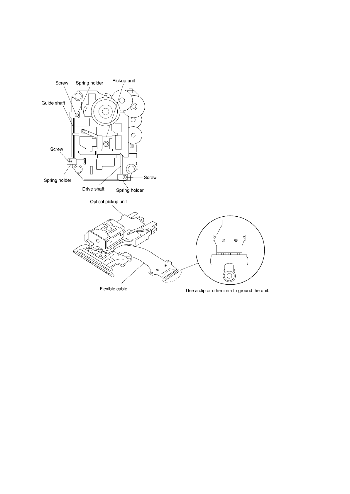
9.7. Optical Pickup Unit
1. Unscrew the screws.
2. Remove the spring holders and the springs.
3. Pull out the drive shaft and guide shaft.
9.7.1. Precautions in optical pickup
replacement
The optical pickup can be damaged by static electricit
y
from you body. Be sure to take static electricit
y
countermeasures when working around the optical picku
p
(Refer to the related page in this Manual about th
e
countermeasures.)
1. Do not touch laser diode, actuator and their peripheries.
2. Do not use tester to check laser diode. (Laser diode can be
damaged easily.)
3. The use of soldering iron with anti-static feature is
recommended when providing short-circuit to laser diode or
when removing it.
4. Solder the land on flexible cable of optical pickup unit.
Caution
x
xx
x When using the soldering iron without anti-static
feature, short-circuit the flexible cable terminal with a
clip before short-circuiting the land.
x
xx
xAfter intended repair is finished, remove the solder
for short-circuit of laser diode in a correct way
following the procedures described in this Manual.
Loading...