


DVD AUDIO-VIDEO/SUPER AUDIO CD PLAYER
DVD-5900
OPERATING INSTRUCTIONS
INSTRUCCIONES DE OPERACION
|
|
|
|
|
|
|
|
POWER |
NTSC / PAL |
OPEN / |
|
|
|
|
|
|
|
|
|
CLOSE |
|||
|
|
|
|
|
|
|
|
ON |
OFF |
|
|
|
|
|
|
|
|
|
|
|
|
|
PROG / DIR |
|
|
|
|
|
|
|
|
1 |
2 |
3 |
|
|
|
|
|
|
|
|
|
|
|
|
CLEAR |
|
|
|
|
|
|
|
|
4 |
5 |
6 |
|
|
|
|
|
|
|
|
|
|
|
|
SRS.TS |
|
|
|
|
|
|
|
|
7 |
8 |
9 |
|
|
|
|
|
|
|
|
|
|
|
CALL |
RETURN |
|
|
|
|
|
|
|
|
0 |
+10 |
|
|
|
|
|
|
|
|
|
|
TOP MENU |
|
|
DISPLAY |
|
|
|
|
|
|
|
|
T. MENU |
|
|
DISP. |
|
|
|
|
|
|
|
|
|
ENTER |
|
|
|
|
|
|
|
|
|
|
|
|
|
PLAY |
|
|
|
|
|
|
|
|
MENU |
|
STILL / |
|
|
|
|
|
|
|
|
|
|
STOP |
|
|
B |
|
|
|
|
|
|
|
|
PAUSE |
|
|
|
|
|
|
|
|
|
|
|
|
|
|
|
|
|
|
PLAY |
STOP |
|
|
SKIP |
SLOW / SEARCH |
||
|
|
|
|
1 |
2 |
8 |
9 |
ANGLE |
SUBTITLE |
AUDIO SEARCH MODE |
|
|
|
|
|
|
|
|
|
||||
|
|
|
|
STILL / PAUSE |
|
|
|
|
|
|
|
|
|
|
|
|
|
|
|
REPEAT |
A-B |
RANDOM |
MARKER |
AL24 PLUS |
DENON LINK |
IEEE 1394 |
|
3 |
|
6 |
7 |
|
|
|
|
|
|
|
|
|
|
|
|
|
|||
POWER |
|
SUPER AUDIO CD |
DVI |
OPEN / CLOSE |
|
MODE SET UP |
|
SETUP |
DIMMER |
PIC.ADJ |
|
|
|
|
|
5 |
MODE |
|
SELECT |
|
|
|
|
¢ON / STANDBY |
|
|
|
|
|
|
|
|
|
||
|
|
|
|
|
|
|
|
|
ZOOM |
PAGE |
|
£OFF |
|
|
|
|
|
|
PUSH ENTER |
|
|
|
|
|
|
REMOTE SENSOR |
|
|
|
DVD AUDIO-VIDEO / SUPER AUDIO CD PLAYER DVD-5900 |
|
|
|
|
|
|
|
|
|
|
|
|
|
|
|
|
|
RC-962
FOR ENGLISH READERS |
PAGE 006 |
~ PAGE 071 |
PARA LECTORES DE ESPAÑOL |
PAGINA 138 |
~ PAGINA 203 |
1
IMPORTANT TO SAFETY
WARNING:
TO PREVENT FIRE OR SHOCK HAZARD, DO NOT EXPOSE THIS APPLIANCE TO RAIN OR MOISTURE.
CAUTION:
1.Handle the power supply cord carefully
Do not damage or deform the power supply cord. If it is damaged or deformed, it may cause electric shock or malfunction when used. When removing from wall outlet, be sure to remove by holding the plug attachment and not by pulling the cord.
2.Do not open the top cover
In order to prevent electric shock, do not open the top cover. If problems occur, contact your DENON DEALER.
3.Do not place anything inside
Do not place metal objects or spill liquid inside the DVD audio-video/ Super audio CD player.
Electric shock or malfunction may result.
Please, record and retain the Model name and serial number of your set
shown on the rating label. |
|
Model No. DVD-5900 |
Serial No. |
CAUTION
RISK OF ELECTRIC SHOCK
DO NOT OPEN
CAUTION:
TO REDUCE THE RISK OF ELECTRIC SHOCK, DO NOT REMOVE COVER (OR BACK). NO USER SERVICEABLE PARTS INSIDE. REFER SERVICING TO QUALIFIED SERVICE PERSONNEL.
The lightning flash with arrowhead symbol, within an equilateral triangle, is intended to alert the user to the presence of uninsulated “dangerous voltage” within the product’s enclosure that may be of sufficient magnitude to constitute a risk of electric shock to persons.
The exclamation point within an equilateral triangle is intended to alert the user to the presence of important operating and maintenance (servicing) instructions in the literature accompanying the appliance.
NOTE:
This DVD audio-video/Super audio CD player uses the semiconductor laser. To allow you to enjoy music at a stable operation, it is recommended to use this in a room of 5 °C (41 °F) ~ 35 °C (95 °F).
CAUTION:
USE OF CONTROLS OR ADJUSTMENTS OR REFORMANCE OF PROCEDURES OTHER THAN THOSE SPECIFIED HEREIN MAY RESULT IN HAZARDOUS RADIATION EXPOSURE.
THE COMPACT DISC PLAYER SHOULD NOT BE ADJUSTED OR REPAIRED BY ANYONE EXCEPT PROPERLY QUALIFIED SERVICE PERSONNEL.
This device complies with Part 15 of the FCC Rules. Operation is subject to the following two conditions: (1) This device may not cause harmful interference, and (2) this device must accept any interference received, including interference that may cause undesired operation.
This Class B digital apparatus meets all requirements of the Canadian Interference-Causing Equipment Regulations.
Cet appareil numérique de la classe B respecte toutes les exigences du Règlement sur le matériel brouilleur du Canada.
• FOR CANADA MODEL ONLY
CAUTION
TO PREVENT ELECTRIC SHOCK, MATCH WIDE BLADE OF PLUG TO WIDE SLOT, FULLY INSERT.
• POUR LES MODELE CANADIENS UNIQUEMENT
ATTENTION
POUR ÉVITER LES CHOCS ÉLECTRIQUES, INTERODUIRE LA LAME LA PLUS LARGE DE LA FICHE DANS LA BORNE CORRESPONDANTE DE LA PRISE ET POUSSER JUSQU’ AU FOND.
2
ENGLISH FRANCAIS ESPAÑOL
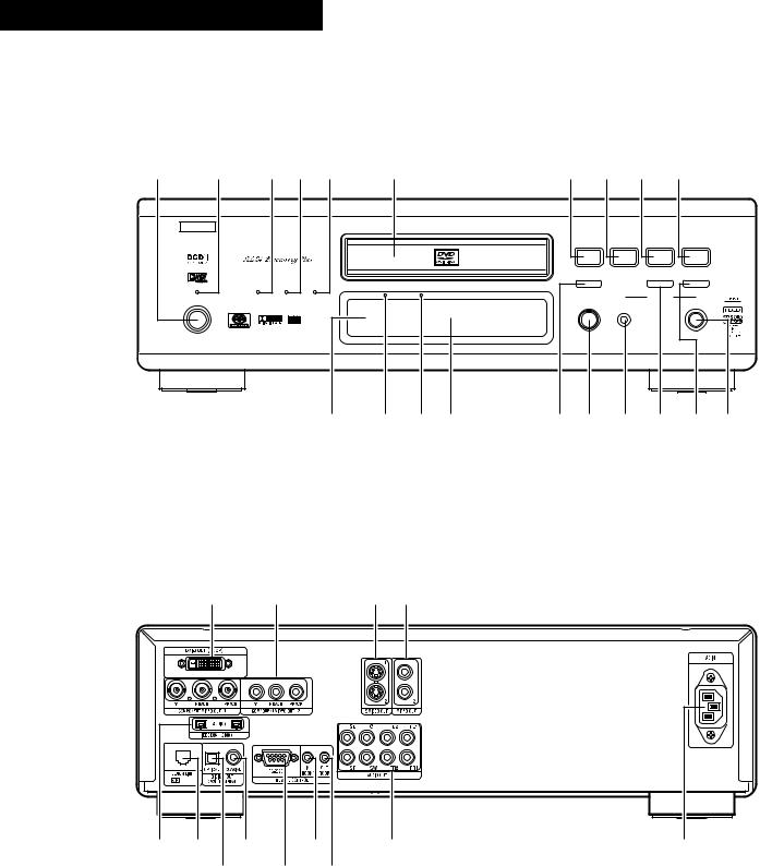
FRONT PANEL
PANNEAU AVANT
PANEL FRONTAL
q |
w |
e r t |
y |
|
u i o !0 |
|||
|
B |
|
|
|
|
|
|
|
|
|
|
|
|
PLAY |
STOP |
|
|
|
|
|
|
|
1 |
2 |
8 |
9 |
|
|
|
|
|
STILL / PAUSE |
|
|
|
|
|
AL24 PLUS DENON LINK IEEE 1394 |
|
|
3 |
|
6 |
7 |
|
|
|
|
|
|
|
|
|
|
POWER |
|
SUPER AUDIO CD |
DVI |
OPEN / CLOSE |
|
MODE SET UP |
|
|
|
|
|
|
|
|||
|
|
|
|
|
5 |
MODE |
|
SELECT |
|
¢ON / STANDBY |
|
|
|
|
|
||
£OFF |
PUSH ENTER |
|
DVD AUDIO-VIDEO / SUPER AUDIO CD PLAYER DVD-5900 |
|
REMOTE SENSOR |
!1 !2!3!4 !5!6!7!8!9@0
REAR PANEL
PANNEAU ARRIERE
PANEL TRASERO
@1 @2 @3@4
@5@6 @8 |
#0 |
#2 |
#3 |
@7 |
@9 #1 |
|
|
3
SAFETY INSTRUCTIONS
1.Read Instructions – All the safety and operating instructions should be read before the product is operated.
2.Retain Instructions – The safety and operating instructions should be retained for future reference.
3.Heed Warnings – All warnings on the product and in the operating instructions should be adhered to.
4.Follow Instructions – All operating and use instructions should be followed.
5.Cleaning – Unplug this product from the wall outlet before cleaning. Do not use liquid cleaners or aerosol cleaners.
6.Attachments – Do not use attachments not recommended by the product manufacturer as they may cause hazards.
7.Water and Moisture – Do not use this product near water – for example, near a bath tub, wash bowl, kitchen sink, or laundry tub; in a wet basement; or near a swimming pool; and the like.
8.Accessories – Do not place this product on an unstable cart, stand, tripod, bracket, or table. The product may fall, causing serious injury to a child or adult, and serious damage to the product. Use only with a cart, stand, tripod, bracket, or table
recommended by the manufacturer, or sold with the product. Any mounting of the product should follow the manufacturer’s instructions, and should use a
mounting accessory recommended by the manufacturer.
9.A product and cart
combination should be moved with care. Quick stops, excessive force, and uneven surfaces may cause the product and cart combination to overturn.
10.Ventilation – Slots and openings in the cabinet are provided for ventilation and to ensure reliable operation of the product and to protect it from overheating, and these openings must not be blocked or covered. The openings should never be blocked by placing the product on a bed, sofa, rug, or other similar surface. This product should not be placed in a built-in installation such as a bookcase or rack unless proper ventilation is provided or the manufacturer’s instructions have been adhered to.
11.Power Sources – This product should be operated only from the type of power source indicated on the marking label. If you are not sure of the type of power supply to your home, consult your product dealer or local power company. For products intended to operate from battery power, or other sources, refer to the operating instructions.
12.Grounding or Polarization – This product may be equipped with a polarized alternating-current line plug (a plug having one blade wider than the other). This plug will fit into the power outlet only one way. This is a safety feature. If you are unable to insert the plug fully into the outlet, try reversing the plug. If the plug should still fail to fit, contact your electrician to replace your obsolete outlet. Do not defeat the safety purpose of the polarized plug.
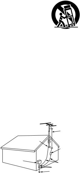
FIGURE A
EXAMPLE OF ANTENNA GROUNDING
AS PER NATIONAL
ELECTRICAL CODE ANTENNA
LEAD IN
WIRE
GROUND
CLAMP
ANTENNA DISCHARGE UNIT
(NEC SECTION 810-20)
ELECTRIC
SERVICE
EQUIPMENT
GROUNDING CONDUCTORS (NEC SECTION 810-21)
GROUND CLAMPS
POWER SERVICE GROUNDING
ELECTRODE SYSTEM (NEC ART 250, PART H)
NEC - NATIONAL ELECTRICAL CODE
13.Power-Cord Protection – Power-supply cords should be routed so that they are not likely to be walked on or pinched by items placed upon or against them, paying particular attention to cords at plugs, convenience receptacles, and the point where they exit from the product.
15.Outdoor Antenna Grounding – If an outside antenna or cable system is connected to the product, be sure the antenna or cable system is grounded so as to provide some protection against voltage surges and built-up static charges. Article 810 of the National Electrical Code, ANSI/NFPA 70, provides information with regard to proper grounding of the mast and supporting structure, grounding of the lead-in wire to an antenna discharge unit, size of grounding conductors, location of antennadischarge unit, connection to grounding electrodes, and requirements for the grounding electrode. See Figure A.
16.Lightning – For added protection for this product during a lightning storm, or when it is left unattended and unused for long periods of time, unplug it from the wall outlet and disconnect the antenna or cable system. This will prevent damage to the product due to lightning and power-line surges.
17.Power Lines – An outside antenna system should not be located in the vicinity of overhead power lines or other electric light or power circuits, or where it can fall into such power lines or circuits. When installing an outside antenna system, extreme care should be taken to keep from touching such power lines or circuits as contact with them might be fatal.
18.Overloading – Do not overload wall outlets, extension cords, or integral convenience receptacles as this can result in a risk of fire or electric shock.
19.Object and Liquid Entry – Never push objects of any kind into this product through openings as they may touch dangerous voltage points or short-out parts that could result in a fire or electric shock. Never spill liquid of any kind on the product.
20.Servicing – Do not attempt to service this product yourself as opening or removing covers may expose you to dangerous voltage or other hazards. Refer all servicing to qualified service personnel.
21.Damage Requiring Service – Unplug this product from the wall outlet and refer servicing to qualified service personnel under the following conditions:
a)When the power-supply cord or plug is damaged,
b)If liquid has been spilled, or objects have fallen into the product,
c)If the product has been exposed to rain or water,
d)If the product does not operate normally by following the operating instructions. Adjust only those controls that are covered by the operating instructions as an improper adjustment of other controls may result in damage and will often require extensive work by a qualified technician to restore the product to its normal operation,
e)If the product has been dropped or damaged in any way, and
f)When the product exhibits a distinct change in performance
– this indicates a need for service.
22.Replacement Parts – When replacement parts are required, be sure the service technician has used replacement parts specified by the manufacturer or have the same characteristics as the original part. Unauthorized substitutions may result in fire, electric shock, or other hazards.
23.Safety Check – Upon completion of any service or repairs to this product, ask the service technician to perform safety checks to determine that the product is in proper operating condition.
24.Wall or Ceiling Mounting – The product should be mounted to a wall or ceiling only as recommended by the manufacturer.
25.Heat – The product should be situated away from heat sources such as radiators, heat registers, stoves, or other products (including amplifiers) that produce heat.
4
ESPAÑOL FRANCAIS ENGLISH
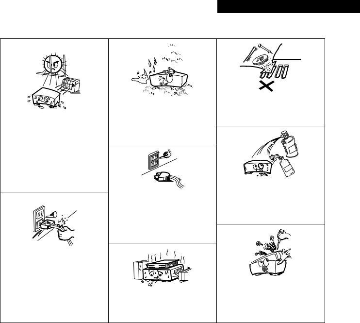
NOTE ON USE / OBSERVATIONS RELATIVES A L’UTILISATION / NOTAS SOBRE EL USO
•Avoid high temperatures.
Allow for sufficient heat dispersion when installed on a rack.
•Eviter des températures élevées.
Tenir compte d’une dispersion de chaleur suffisante lors de l’installation sur une étagère.
•Evite altas temperaturas.
Permite la suficiente dispersión del calor cuando está instalado en la consola.
•Handle the power cord carefully.
Hold the plug when unplugging the cord.
•Manipuler le cordon d’alimentation avec précaution.
Tenir la prise lors du débranchement du cordon.
•Maneje el cordón de energía con cuidado. Sostenga el enchufe cuando desconecte el cordón de energía.
•Keep the set free from moisture, water, and dust.
•Protéger l’appareil contre l’humidité, l’eau et lapoussière.
•Mantenga el equipo libre de humedad, agua y polvo.
•Unplug the power cord when not using the set for long periods of time.
•Débrancher le cordon d’alimentation lorsque l’appareil n’est pas utilisé pendant de longues périodes.
•Desconecte el cordón de energía cuando no utilice el equipo por mucho tiempo.
(For sets with ventilation holes)
•Do not obstruct the ventilation holes.
•Ne pas obstruer les trous d’aération.
•No obstruya los orificios de ventilación.
•Do not let foreign objects in the set.
•Ne pas laisser des objets étrangers dans l’appareil.
•No deje objetos extraños dentro del equipo.
•Do not let insecticides, benzene, and thinner come in contact with the set.
•Ne pas mettre en contact des insecticides, du benzène et un diluant avec l’appareil.
•No permita el contacto de insecticidas, gasolina y diluyentes con el equipo.
•Never disassemble or modify the set in any way.
•Ne jamais démonter ou modifier l’appareil d’une manière ou d’une autre.
•Nunca desarme o modifique el equipo de ninguna manera.
Copyrights / Droits d’auteur / Derechos de Autor
2 It is prohibited by law to reproduce, |
2 La reproduction, la diffusion, la |
broadcast, rent or play discs in public |
location, le prêt ou la lecture publique |
without the consent of the copyright |
de ces disques sont interdits sans le |
holder. |
consentement du détenteur des droits |
|
d’auteur. |
2De acuerdo con las leyes está prohibido reproducir, emitir, alquilar o interpretar discos en público sin la autorización del propietario de los derechos de autor.
5
ENGLISH
— TABLE OF CONTENTS —
z Features................................................................................... |
6, 7 |
x Discs ............................................................................................ |
8 |
c Cautions on Handling Discs......................................................... |
9 |
v Connections ...................................................................... |
10 ~ 18 |
b Part Names and Functions .................................................. |
19, 20 |
n Remote Control Unit............................................................ |
21, 22 |
m Loading Discs ............................................................................ |
23 |
, Changing the Default Settings .......................................... |
24 ~ 41 |
. Playback ............................................................................ |
42 ~ 46 |
⁄0Using the Mode Set Up....................................................... |
47, 48 |
⁄1Adjusting the Picture Quality ............................................ |
48 ~ 51 |
⁄2Using the On-Screen Display..................................................... |
52 |
⁄3Playing Repeatedly .............................................................. |
53, 54 |
⁄4Playing Tracks in the Desired Order .......................................... |
55 |
⁄5Playing Tracks in the Random Order ......................................... |
56 |
⁄6Playing Back WMA .................................................................... |
57 |
⁄7MP3 Playback ...................................................................... |
58, 59 |
⁄8Playing Still Picture Files (JPEG format)............................ |
60 ~ 62 |
⁄9Using the Multiple Audio, Subtitle and Angle Functions....... |
63 ~ 65 |
¤0Using the Menus................................................................. |
66, 67 |
¤1Marking Scenes you want to see again .................................... |
68 |
¤2Playing in the Zoom Mode ........................................................ |
69 |
¤3Troubleshooting ......................................................................... |
70 |
¤4Main Specifications.................................................................... |
71 |
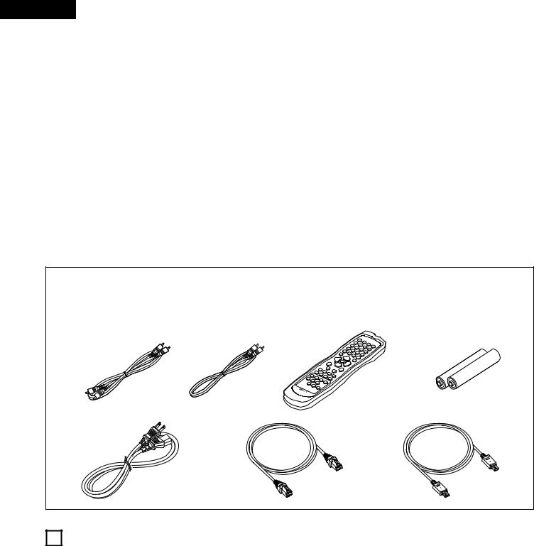
• ACCESSORIES
Please check to make sure the following items are included with the main unit in the carton:
q Audio cord ................................................................................ |
1 |
w Video cord................................................................................. |
1 |
e Remote control unit (RC-962)................................................... |
1 |
r R6P/AA batteries ...................................................................... |
2 |
t Power supply cord.................................................................... |
1 |
y DENON LINK cord.................................................................... |
1 |
u IEEE 1394 cord......................................................................... |
1 |
i Operating instructions .............................................................. |
1 |
o Service station list .................................................................... |
1 |
q |
w |
e |
r |
y |
u |
t
1FEATURES
1.Digital transfer connectors
The DVD-5900 can be connected to another digital transfer compatible Denon component (AV amplifier, etc.) using a single cable (included) for high quality digital sound with little transfer loss.
(1)Denon Link terminal
This terminal can be used for digital transfer of not only DVD video signals, but also multi-channel audio signals of DVD audio.
(2)IEEE 1394 terminal
This terminal can be used for digital transfer of not only DVD video signals, but also DVD audio signals, Super Audio CD signals and other multi-channel audio signals.
2.Super Audio CD multi-channel playback compatibility
In addition to playing DVD audio and video discs, the DVD5900 can play multi-channel Super Audio CDs with a playback frequency range covering 100 kHz and a dynamic range of 120 dB or greater within the audible frequency range, and a maximum of 5.1 channels can be output.
6

3.AL24 Processing Plus at all channel
AL24 Processing Plus compensates the input digital data to reproduce the sound with analog waveforms as close as possible to those existing in nature and with 24-bit quality. The result is increased musical reproduction capabilities of reverberations, etc., at low levels, for a sound that seems to draw you into the concert hall.
Equipped for not only the front left and right channels but also for the surround left and right, center and subwoofer channels.
4.High precision 24-bit D/A converter
The audio playback circuit includes an advanced segment type D/A converter with the top technical specifications in the business, manufactured by Burr-Brown, a company with an established reputation for D/A converters. This high performance D/A converter allows not only input of the 24bit/192 kHz data of DVD-Audio discs, it also includes an analog pure FIR filter for ideal DSD playback of Super Audio CDs. Furthermore, the same DAC is used unsparingly for the surround, center and LFE channels to provide optimum sound quality during multi-channel playback as well.
5.HDCD® (High Definition Compatible Digital®) decoder (NOTE 1)
HDCD is an encoding/decoding technology that greatly reduces the distortion occurring at the time of digital recording while maintaining compatibility with the conventional CD format. HDCD allows 20-bit data to be converted into the 16bit data of current CDs with no loss in sound quality.
The use of this HDCD decoder makes it possible to achieve the high resolution and low distortion characteristic of HDCD when playing HDCD-compatible discs, and DENON’s digital technology optimizes the high sound quality possibilities of HDCD technology. Furthermore, normal CDs and HDCDcompatible CDs are automatically identified, and the optimum digital signal processing for that type of disc is used.
6.Dolby Digital (AC-3)/DTS decoder (NOTE 2, 3)
The DVD-5900 is equipped with a built-in Dolby Digital (AC-3) /DTS decoder, allowing you to recreate the atmosphere of a movie theater or concert hall when using the DVD-5900 in combination with an AV amplifier and speakers.
7.Progressive Scan circuit “DCDiTM” (NOTE 4)
The DVD-5900 is equipped with a high precision Progressive Scan circuit “DCDi™” allowing it to reproduce movies and other images on DVDs with a quality near that of the original.
8.12-bit/216 MHz video D/A converter (NOTE 5)
The DVD-5900 uses a video D/A converter that conducts D/A conversion of all video signals at 12 bits and allows 8X oversampling in the progressive mode to achieve the high quality picture that DVDs are meant to provide. In addition, NSV technology reduces noise upon D/A conversion.
9.Thorough vibration-resistant design
(1)Mechanism using a hybrid loader.
(2)The pickup mechanism is positioned at the center to reduce the effects of external vibrations.
(3)A heavyweight chassis and low center of gravity make for a low vibration design.
ENGLISH
10.Multiple functions
(1)Still picture playback function
Kodak Picture CD (NOTE 6) and Fujifilm Fujicolor CD (NOTE 7) can be played on the DVD-5900.
Still images stored in JPEG format on CD-R/RWs can also be played.
(2)Windows Media™ playback function (NOTE 8) Windows Media™ CDs can be played on the DVD-5900.
(3)Multiple audio function
Selection of up to 8 audio languages.
(The number of languages offered differs from DVD to DVD.)
(4)Multiple subtitle function
Selection of up to 32 subtitle languages.
(The number of languages offered differs from DVD to DVD.)
(5)Multiple angle function
The angle of view can be changed.
(For DVDs on which multiple angles are recorded.)
(6)GUI (Graphical User Interface) function
The DISPLAY button on the remote control unit can be used to display player and disc information on the TV screen.
(7)Marker function
The positions of up to five scenes can be stored in the memory, so you can watch your favorite scenes whenever you want.
(8)Playback disable function
This function can be used to disable playback of DVDs you do not want children to watch.
NOTES:
1. ®, HDCD®, High Definition Compatible Digital® and Microsoft® are either registered trademarks or trademarks of
Microsoft Corporation, Inc. in the United States and/or other countries. HDCD system manufactured under license from Microsoft Corporation, Inc. This product is covered by one or more of the following: In the USA: 5,479,168, 5,638,074, 5,640,161, 5,808,574, 5,838,274, 5,854,600, 5,864,311, 5,872,531, and in Australia: 669114. Other patents pending.
2.Manufactured under license from Dolby Laboratories. “Dolby” and the double-D symbol are trademarks of Dolby Laboratories. Confidential Unpublished Work. ©1992 – 1998 Dolby Laboratories, Inc. All rights reserved.
3.“DTS” and ”DTS Digital Surround” are registered trademarks of Digital Theater Systems, Inc.
4.“DCDi™” is trademark of Faroodja, a division of Genesis Microchip Inc.
5.“NSV” is a trademark of Analog Devices, Inc.
6.“KODAK” is a trademark of Eastman Kodak Company.
7.“FUJICOLOR CD” is a trademark of Fuji Photo Film Co, Ltd.
8.“Windows Media™”, “Windows™”are a trademarks of Microsoft Corporation, Inc.
7
ENGLISH
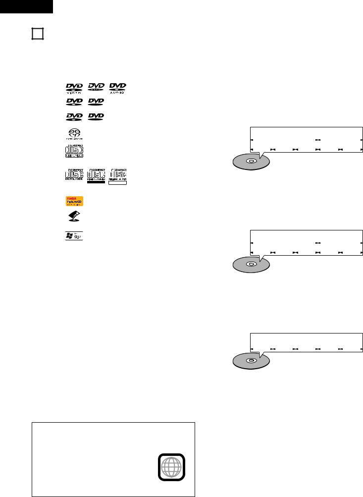
2DISCS
•The types of discs listed on the table below can be used on the DVD-5900. The marks are indicated on the disc labels or jackets.
Usable |
|
Mark (logo) |
|
Recorded |
Disc size |
|
discs |
|
|
signals |
|||
|
|
|
|
|
||
|
|
|
|
|
|
|
DVD video |
|
|
|
|
|
12 cm |
DVD audio |
|
|
|
|
|
|
(NOTE 1) |
|
|
|
|
Digital audio + |
|
|
|
|
R |
|
digital video |
|
|
|
|
|
|
||
DVD-R |
R |
|
(MPEG2) |
|
||
|
|
|
|
|
||
DVD-RW |
|
|
|
|
|
8 cm |
(NOTE 2) |
|
|
R W |
|
|
|
|
R W |
|
|
|
||
|
|
|
|
|
|
|
Super |
|
|
|
|
Digital audio |
12 cm |
audio CD |
|
|
|
|
||
|
|
|
|
|
|
|
|
|
|
|
|
|
|
Video CD |
|
|
|
|
Digital audio + |
12 cm |
|
|
|
|
digital video |
|
|
(NOTE 1) |
|
|
|
|
8 cm |
|
|
|
|
|
(MPEG1) |
||
|
|
|
|
|
||
CD |
|
|
|
|
Digital audio |
12 cm |
|
|
|
|
MP3 |
||
CD-R |
|
|
|
|
|
|
CD-RW |
|
|
Recordable |
ReWritable |
Digital picture |
|
(NOTE 3) |
|
|
8 cm |
|||
|
|
|
|
|||
|
|
|
|
|
(JPEG) |
|
|
|
|
|
|
|
|
Picture CD |
|
|
|
|
JPEG |
12 cm |
|
|
|
|
|
|
|
Fujicolor |
|
|
|
|
JPEG |
12 cm |
CD |
|
|
|
|
||
|
|
|
|
|
|
|
|
|
|
|
|
|
|
WMA |
|
|
|
|
|
|
(Windows |
|
|
|
|
Digital audio |
12 cm |
Media |
|
|
|
|
||
|
|
|
|
|
|
|
Audio) |
|
|
|
|
|
|
|
|
|
|
|
|
|
2Disc terminology
•Groups and tracks (DVD-audios)
DVD-audios are divided into several large sections called “groups” and smaller sections called “tracks”.
Numbers are allotted to these sections. These numbers are called “group numbers” and “track numbers”.
For example:
|
|
|
|
Group 1 |
|
|
|
|
|
Group 2 |
|||
|
|
|
|
|
|
|
|
|
|||||
Track 1 |
|
|
|
Track 2 |
|
|
|
Track 3 |
|
Track 1 |
|
|
Track 2 |
•Titles and chapters (DVD-videos)
DVD-videos are divided into several large sections called “titles” and smaller sections called “chapters”.
Numbers are allotted to these sections. These numbers are called “title numbers” and “chapter numbers”.
For example:
|
|
|
Title 1 |
|
Title 2 |
|||||
|
|
|
|
|||||||
Chapter 1 |
Chapter 2 |
Chapter 3 |
|
Chapter 1 |
Chapter 2 |
|||||
|
|
|
|
|
|
|
|
|
|
|
2The following types of discs cannot be played on the DVD-5900:
•DVDs with region numbers other than “1” or “ALL”
•DVD-ROM/RAMs
•CD-ROMs (unless MP3, JPEG, WMA Files)
•CVD/VSDs
•CDVs (Only the audio part can be played.)
•CD-Gs (Only the audio is output.)
•Photo CDs
NOTE 1: Some DVD audio, DVD video and video CD discs do not operate as described in this manual due to the intentions of the discs’ producers.
NOTE 2: Playing DVD-R and DVD-RW discs
DVD-R and DVD-RW discs recorded in video format on a DVD recorder can be played on the DVD-5900.
Discs that have not be finalized cannot be played. Depending on the disc’s recording status, the disc may not be accepted or may not be played normally (the picture or sound may be not be smooth, etc.).
NOTE 3: According to recording quality, some CD-R/RW cannot be played.
NOTE:
•This DVD player is designed and manufactured to respond to the Region Management Information that is recorded on a DVD disc.
If the Region number described on the
DVD disc does not correspond to the |
1 |
|
|
Region number of this DVD player, this |
|
DVD player cannot play this disc. |
|
The Region number for this DVD player is 1. |
|
•Tracks (Super audio CDs, video and music CDs)
Super audio CDs, video and music CDs are divided into sections called “tracks”.
Numbers are allotted to these sections. These numbers are called “track numbers”.
For example:
Track 1 |
|
|
|
Track 2 |
|
|
|
Track 3 |
|
|
Track 4 |
|
|
Track 5 |
•Playback control (video CDs)
Video CDs including the words “playback control” on the disc or jacket are equipped with a function for displaying menus on the TV screen for selecting the desired position, displaying information, etc., in dialog fashion.
In this manual, playing video CDs using such menus is referred to “menu playback”.
Video CDs with playback control can be used on the DVD5900.
8
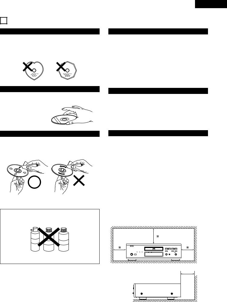
3 CAUTIONS ON HANDLING DISCS
Discs
Only the discs including the marks shown on page 8 can be played on the DVD-5900.
Note, however, that discs with special shapes (heart-shaped discs, hexagonal discs, etc.) cannot be played on the DVD-5900. Do not attempt to play such discs, as they may damage the player.
Holding Discs
Avoid touching the surface of discs when loading and unloading them.
Be careful not to get fingerprints on the signal surface (the side which shines in rainbow colors).
ENGLISH
Cautions on Handling Discs
•Do not get fingerprints, grease or dirt on discs.
•Be especially careful not to scratch discs when removing them from their cases.
•Do not bend discs.
•Do not heat discs.
•Do not enlarge the center hole.
•Do not write on the labeled (printed) side with a ball-point pen or a pencil.
•Water droplets may form on the surface if the disc is moved suddenly from a cold place to a warm one. Do not use a hairdryer, etc., to dry the disc.
Cautions on Storing Discs
•Always eject discs after playing them.
•Keep discs in their cases to protect them from dust, scratches and warping.
•Do not put discs in the following places:
1.Places exposed to direct sunlight for long periods of time
2.Humid or dusty places
3.Places exposed to heat from heaters, etc.
Cleaning Discs
2Fingerprints or dirt on the disc may lower sound and picture quality or cause breaks in playback. Wipe off fingerprints or dirt.
2Use a commercially available disc cleaning set or a soft cloth to wipe off fingerprints or dirt.
Wipe gently from the middle |
Do not wipe with a circular |
outwards. |
motion. |
NOTE:
•Do not use record spray or antistatic. Also do not use volatile chemicals such as benzene or thinner.
Record Thinner Benzene
spray
Cautions on Loading Discs
•Only load one disc at a time. Loading one disc on top of another may result in damage or scratch the discs.
•Load 8 cm discs securely in the disc guide, without using an adapter. If the disc is not properly loaded, it may slip out of the guide and block the disc tray.
•Be careful not to let your fingers get caught when the disc tray is closing.
•Do not place anything but discs in the disc tray.
•Do not load cracked or warped discs or discs that have been fixed with adhesive, etc.
•Do not use discs on which the adhesive part of cellophane tape or glue used to attach the label is exposed, or discs with traces of tape or labels that have been peeled off. Such discs may get stuck inside the player, resulting in damage.
CAUTIONS ON INSTALLATION
For heat dispersal, leave at least 10 cm of space between the top, back and sides of this unit and the wall or other components.
10 cm or more |
B |
10 cm or more
wall |
9
ENGLISH
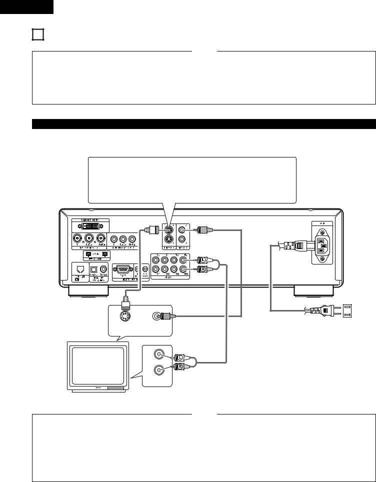
4 CONNECTIONS
NOTES:
•Read the manuals of all the components when making connections.
•Keep the power supply cord unplugged until all connections have been completed.
•If the power is on when connections are made, noise may be generated and damage the speakers.
•Be sure to connect the left and right channels properly, L (left) to L, R (right) to R.
•Plug the power supply cord securely into the power outlet. Incomplete connection may result in noise.
•Binding the power supply cord together with connection cords may result in humming or noise.
(1)Connecting to a TV
•Use the included audio video cord to connect the TV’s video input connector and audio input connectors to the DVD-5900’s VIDEO OUT or S-VIDEO OUT and AUDIO OUT.
S-Video output connector
The video signals are divided into color (C) and brightness (Y) signals, achieving a clearer picture.
If the TV is equipped with an S-Video input connector, we recommend connecting it to the DVD-5900’s S-Video output connector using a commercially available
S-Video connection cord.
DVD-5900
To power outlet
S-VIDEO IN VIDEO IN
TV
L
R
AUDIO IN
NOTES:
•Connect the DVD-5900’s video outputs to the TV either directly or through an AV amplifier. Do not connect it via a VCR (video cassette recorder). Some discs contain copy prohibit signals. If such discs are played via a VCR, the copy prohibit system may cause disturbance in the picture.
•Set the “TV TYPE” in “VIDEO SETUP” in “SETUP” to comply with your TV’s video format. When the TV is NTSC formated set to NTSC. (See page 31.)
•To use with 2-channel audio output, set “2 CHANNEL” in “AUDIO CHANNEL” in “AUDIO SETUP” in “SETUP” at the initial settings. (See page 33.)
•Set the “TV ASPECT” in “VIDEO SETUP” in “SETUP” to comply with your TV’s aspect. (See page 31)
•To use with video out or s-video output, set “INTERLACED” in “VIDEO OUT” in “VIDEO SETUP” in “SETUP” at the initial settings. (See page 32.)
10
ENGLISH
(2) Connecting to a TV or Monitor Equipped with Color Component Input Connectors
Color component output connectors (PR/CR, PB/CB and Y)
The red (PR/CR), blue (PB/CB) and brightness (Y) signals are output independently, achieving more faithful reproduction of the colors.
•The color component input connectors may be marked differently on some TVs or monitors (PR, PB and Y/R- Y, B-Y and Y/CR, CB and Y, etc.). For details, refer to the TV’s operating instructions.
•Connect in this way if your TV is compatible with Progressive Scan.
DVD-5900
To power outlet
TV
Y PB/CB PR/CR |
L |
R |
COMPONENT VIDEO IN |
AUDIO IN |
|
NOTES:
•Use the three commercially available video cords to connect the DVD-5900’s color component output connectors to the TV or monitor.
•Set the “TV TYPE” in “VIDEO SETUP” in “SETUP” to comply with your TV’s video format. When the TV is NTSC formated set to NTSC. (See page 31.)
•Set the “VIDEO OUT” in “VIDEO SETUP” in “SETUP” to comply with Progressive TV.
•To use with 2-channel audio output, set “2 CHANNEL” in “AUDIO CHANNEL” in “AUDIO SETUP” in “SETUP” at the initial settings. (See page 33.)
•Set the “TV ASPECT” in “VIDEO SETUP” in “SETUP” to comply with your TV’s aspect. (See page 31.)
CONSUMERS SHOULD NOTE THAT NOT ALL HIGH DEFINITION TELEVISION SETS ARE FULLY COMPATIBLE WITH THIS PRODUCT AND MAY CAUSE ARTIFACTS TO BE DISPLAYED IN THE PICTURE. IN CASE OF 525 PROGRESSIVE SCAN PICTURE PROBLEMS, IT IS RECOMMENDED THAT THE USER SWITCH THE CONNECTION TO THE “STANDARD DEFINITION” OUTPUT.
11
ENGLISH
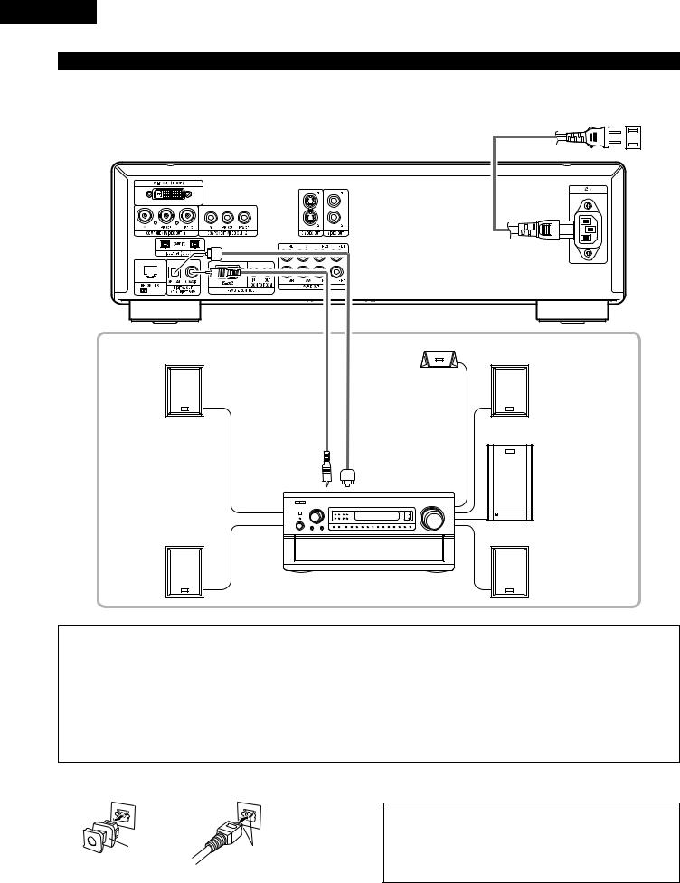
(3) Connecting to a AV amplifier with a built-in decoder
When DVDs recorded in Dolby Digital or DTS are played, Dolby Digital or DTS bitstream signals are output from the DVD player’s digital audio output connectors. If a Dolby Digital or DTS decoder is connected, you can achieve sound with the power and sense of presence of a movie
theater or concert hall.
To power outlet
DVD-5900
|
Center speaker |
|
|
Front speaker (left) |
|
Front speaker (right) |
|
75Ω/ohms pin-plug |
(or) Optical fiber cable |
|
|
cable (commercially |
(commercially |
|
|
available) |
available) |
|
|
Digital audio input |
Digital audio input |
Subwoofer |
|
connector (COAXIAL) |
connector (OPTICAL) |
||
|
Surround speaker (left) |
Surround speaker (right) |
AV amplifier with a built-in decoder (AV control center)
NOTES:
•Harsh noise that could harm your ears or damage the speakers is generated when a DVD recorded in DTS is played while using a decoder, etc., that is not DTS-compatible.
•When playing copyright-protected linear PCM or packed PCM DVDs, in consideration of copyrights, no digital signals are output for sources exceeding 48 kHz/16 bits. When playing such sources, either set “LPCM (44.1 kHz/48 kHz)” under “AUDIO SETUP” at “SETUP” to “ON” (see page 36) or make analog connections. (See page 14.)
•When making digital connections to an AV amplifier that is not compatible with 96 kHz/88.2 kHz signals, set “LPCM (44.1 kHz/48 kHz)” under “AUDIO SETUP” at “SETUP” to “ON”. (See page 36.)
•With Super audio CDs, digital audio signals cannot be output. Use analog connections. (See page 14, 15.)
2 Connecting an optical fiber cable (commercially available) to the digital audio input connector (OPTICAL)
NOTE:
• Store the dust cap in a safe place, and be careful not to lose it.
Dust cap |
Line up in proper direction |
When not using the terminal, attach the cap to protect the |
terminal from dust.
Remove the dust cap, line up the cable in the proper directly, then insert it securely as far as it goes.
12

ENGLISH
2Sound output from the DVD-5900’s digital audio output connectors
In the case of bit stream output
|
|
Settings |
|
|
|
|
|
|
|
|
|
DIGITAL OUT |
|
|
|
|
|
|
|
|
Audio recording format |
NORMAL |
|
PCM |
|
|
|
|
|
|
Dolby Digital |
Dolby Digital bitstream |
|
2 channels PCM |
|
|
(48 kHz / 16 bit) |
||
|
|
|
|
|
DVD video |
|
|
|
|
DTS |
DTS bitstream |
|
2 channels PCM |
|
|
|
|||
|
|
(48 kHz / 16 bit) |
||
|
|
|
|
|
|
|
|
|
|
In the case of PCM output
|
|
|
|
Settings |
|
|
|
|
|
|
|
|
|
|
|
|
|
LPCM SELECT |
|
|
|
|
|
|
|
|
|
|
Audio recording format |
|
OFF |
ON |
||
|
|
|
||||
|
Copy protection ON |
Copy protection OFF |
||||
|
|
|
|
|||
|
|
|
|
|
|
|
DVD video |
Linear PCM |
48 kHz / 16 ~ 24 bit |
No output data (*1) |
48 kHz / 16 ~ 24 bit PCM |
48 kHz / 16 bit PCM |
|
|
|
|
|
|||
96 kHz / 16 ~ 24 bit |
No output data |
96 kHz / 16 ~ 24 bit PCM |
48 kHz / 16 bit PCM |
|||
|
|
|||||
|
|
|
|
|
|
|
|
|
44.1 kHz / 16 ~ 24 bit |
No output data (*2) |
44.1 kHz / 16 ~ 24 bit PCM |
44.1 kHz / 16 bit PCM |
|
|
|
|
|
|
|
|
|
|
48 kHz / 16 ~ 24 bit |
No output data (*1) |
48 kHz / 16 ~ 24 bit PCM |
48 kHz / 16 bit PCM |
|
|
Linear PCM |
|
|
|
|
|
DVD audio |
88.2 kHz / 16 ~ 24 bit |
No output data |
88.2 kHz / 16 ~ 24 bit PCM |
44.1 kHz / 16 bit PCM |
||
or |
|
|
|
|
||
96 kHz / 16 ~ 24 bit |
No output data |
96 kHz / 16 ~ 24 bit PCM |
48 kHz / 16 bit PCM |
|||
|
Packed PCM |
|||||
|
|
|
|
|
|
|
|
|
176.4 kHz / 16 ~ 24 bit |
No output data |
88.2 kHz / 16 ~ 24 bit PCM |
44.1 kHz / 16 bit PCM |
|
|
|
|
|
|
|
|
|
|
192 kHz / 16 ~ 24 bit |
No output data |
96 kHz / 16 ~ 24 bit PCM |
48 kHz / 16 bit PCM |
|
|
|
|
|
|
||
Video CD |
|
MPEG 1 |
44.1 kHz / 16 bit PCM |
44.1 kHz / 16 bit PCM |
||
|
|
|
|
|||
Music CD |
44.1 kHz / 16 bit Linear PCM |
44.1 kHz / 16 bit PCM |
44.1 kHz / 16 bit PCM |
|||
|
|
|
|
|||
MP3 CD |
MP3 (MPEG-1 Audio Layer 3) |
44.1, 48 kHz / 16 bit PCM |
44.1, 48 kHz / 16 bit PCM |
|||
|
|
|
|
|||
WMA CD |
WMA (Windows Media Audio) |
44.1, 48 kHz / 16 bit PCM |
44.1, 48 kHz / 16 bit PCM |
|||
|
|
|
|
|||
Super audio CD |
DSD (DIRECT STREAM DIGITAL) |
No output data (*3) |
No output data (*3) |
|||
|
|
|
|
|
|
|
*1 Only 48 kHz/16 bit sources are output.
*2 Only 44.1 kHz/16 bit sources are output.
*3 44.1 kHz/16-bit PCM signals are output during CD layer playback.
•Down-mixed to 2 channels for multi-channel PCM sources. (Only the front left and right channels are output for sources for which downmixing is prohibited.)
•When “OFF” is selected, digital signals are not output from the digital audio output at this time.
•Bitstream signals are signals that are compressed and converted into digital format. They are decoded into multi-channel audio signals (5.1-channels, etc.) by the decoder.
•Linear PCM audio is the signal recording format used for music CDs.
While the signals are recorded at 44.1 kHz/16 bit for music CDs, for DVDs they are recorded at 44.1 kHz/16 bit to 192 kHz/24 bit, providing higher sound quality than music CDs.
•Packed PCM signals are high sound quality compressed PCM signals that are decompressed with virtually no loss of data.
13
ENGLISH
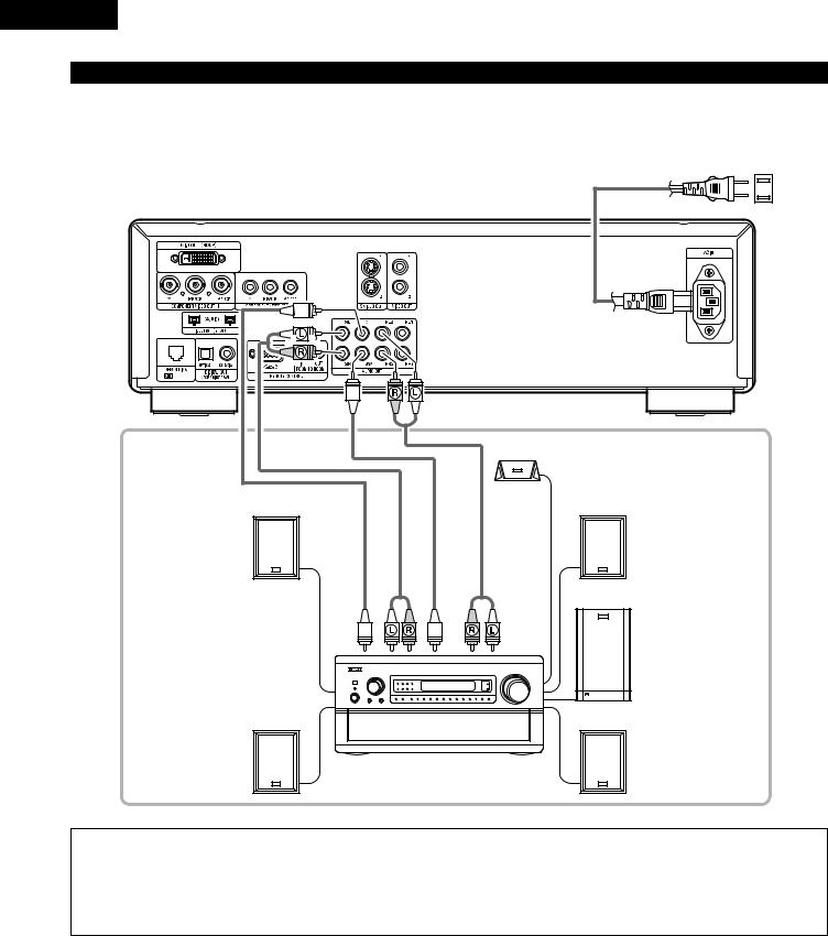
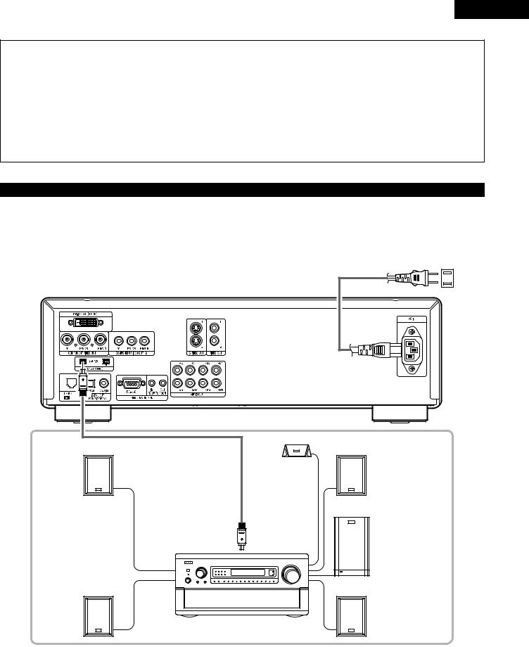
(4) Connecting a basic 5.1-channel surround system
Analog 5.1-channel audio signals can be output from the DVD-5900.
The multichannel audio signals recorded in packed PCM and the multichannnel Super audio CDs can be played when an AV amplifier equipped with analog 5.1-channel audio inputs is connected.
To power outlet
DVD-5900
|
|
|
Center speaker |
Front speaker (left) |
|
|
Front speaker (right) |
CENTER |
SURROUND |
SUBWOOFER |
FRONT |
|
|
|
Subwoofer |
Surround speaker (left) |
Surround speaker (right) |
AV amplifier with 5.1-channel input terminals
NOTES:
•For multi-channel connections, set “AUDIO CHANNEL” under “AUDIO SETUP” at “SETUP” to “MULTI CHANNEL” and make the “SPEAKER CONFIGURATION”, “CHANNEL LEVEL” and “DELAY TIME” settings. (See pages 33 ~ 35.)
•With the DVD-5900, we recommend turning the digital output off and only outputting analog signals in order to keep interference from the digital output circuitry to the minimum and allow you to enjoy high bit, high sampling frequency, high quality multi-channel sound.
14
ENGLISH
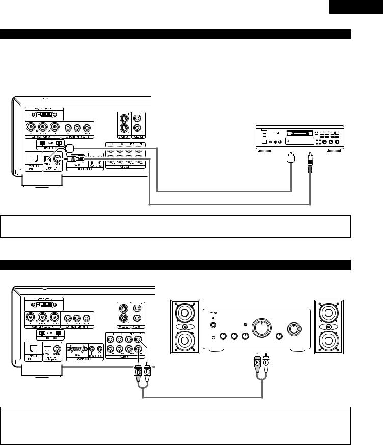
(5)Connecting to a Digital Recorder (MD Recorder, DAT Deck, etc.)
Set the “AUDIO SETUP” default setting as shown below. (See page 36.)
• “DIGITAL OUT” → “PCM” “LPCM (44.1kHz/48kHz)” → “ON”
Playing DVDs with incorrect settings may result noise that could damage your ears or the speakers.
DVD-5900
B |
|
Digital audio |
Digital audio |
input connector |
input connector |
(OPTICAL) |
(COAXIAL) |
Optical fiber cable (commercially available) |
|
(or) |
|
75Ω/ohms pin-plug cable (commercially available) |
|
NOTE: |
|
• Digital audio signals cannot be output when playing Super Audio CDs. Use analog connections to record Super Audio CDs.
(6) Connecting to a Stereo Component
DVD-5900
Stereo component
NOTE:
•When connecting to a 2-channel audio stereo device, set “AUDIO CHANNEL” under “AUDIO SETUP” at “SETUP” to “2 CHANNEL” (see page 33). For multi-channel sources, the signals are down-mixed into two channels (analog).
(Only the front left and right channels are output for sources for which down-mixing is prohibited.)
15
ENGLISH
(7) Denon Link connections
High quality digital sound with reduced digital signal transfer loss can be enjoyed by connecting a separately sold Denon Link compatible AV amplifier.
To power outlet
DVD-5900
Front speaker (left)
DENON LINK
Center speaker
Front speaker (right)
Subwoofer
Surround speaker (left) |
Surround speaker (right) |
AV amplifier with Denon Link input terminals
2DENON LINK Second Edition:
•With the DENON LINK, Second Edition (2nd), the audio signals are transferred from the DVD player to the AV amplifier in digital form, with the same quality as the signals recorded on the disc.
Digital transfer of the high quality multi-channel signals of DVD audio is possible for all discs. (A Second Edition compatible DVD player and AV amplifier are required for this.)
2Compatibility with previous models:
•With Second Edition, the format of the signals handled differs from that of the previous version of DENON LINK.
Thus, digital audio signals output from a DENON LINK S.E. (2nd) compatible DVD player can only be played on a DENON LINK S.E. (2nd) compatible AV amplifier (Playback with DENON LINK connections is not possible when using a DENON LINK S.E. compatible DVD player in combination with an AV amplifier that is not S.E. compatible.).
•If the DENON LINK connector on your AV amplifier is not S.E. compatible, please consult your authorized DENON dealer.
•“S.E.” is indicated on the rear panel’s DENON LINK connector on DENON LINK S.E. compatible products.
2DENON LINK S.E. settings:
•At “AUDIO SETUP” under “Default Settings”, set “DENON LINK” to “2nd”. (See pages 33 to 37.)
•(If you connect the DENON LINK, set to “2nd”.)
16
ENGLISH
NOTES:
•When DENON LINK is set, the down-mixed audio signals are output from the only front left and right terminals. To use the analog terminals, cancel the DENON LINK setting (set to “OFF”).
•“AUDIO CHANNEL”, “DIGITAL OUTPUT”, “LPCM (44.1kHz/48kHz)”, “IEEE 1394”, “SOURCE DIRECT” and “BASS ENHANCER” cannot be set at “AUDIO SETUP” under “Default Settings” when using the DENON LINK connector.
•When using the DENON LINK, select something other than “DIGITAL OFF” or “ALL OFF” at “PURE DIRECT”. If “DIGITAL OFF” or “ALL OFF” are selected, the digital circuit is stopped and signals cannot be output from the DENON LINK connector.
•The DVD-5900’s speaker settings are invalidated when the DENON LINK connector is connected.
•When the DENON LINK 2nd connection, Super Audio CD’s signals are not output from the DENON LINK connector. Please use the analog audio output terminals.
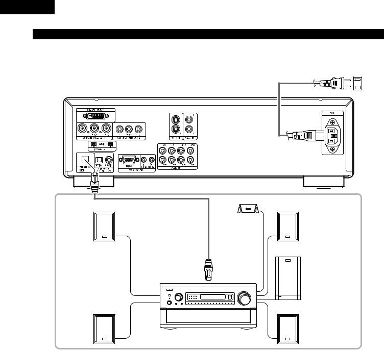
(8) IEEE 1394 connections
The simple connection of one IEEE 1394 cable permits high quality digital transfer of the following between devices having IEEE 1394 connectors: the audio of DVD video, DVD audio that up until now could only be connected by 5-conductor audio cable in an analog connection, or Super Audio CD and other multi-channel audio. (unless DENON LINK connections)
(IEEE 1394 is an international standard established by the Institute of Electrical and Electronics Engineers, Inc. of the U.S.)
To power outlet
DVD-5900
Center speaker |
Front speaker (left) |
Front speaker (right) |
IEEE 1394 |
Subwoofer |
Surround speaker (left) |
Surround speaker (right) |
AV amplifier with IEEE 1394 terminals
17

ENGLISH
NOTES:
•Please use the included IEEE 1394 cable. When using a cable other than the included IEEE 1394 cable, please use a 4-pin IEEE 1394 cable with a length of 3.5 m or less for S400 or higher.
•The “IEEE 1394 audio signal (A&M protocol)” output from the DVD-5900’s IEEE 1394 connector not out video signals, please connecting to a TV or Monitor with “component video output” or “S-video output” or “Video output”. (See pages 10, 11).
•The “IEEE 1394 audio signal (A&M protocol)” output from the DVD-5900’s IEEE 1394 connector can only be received on AV equipment equipped with an IEEE 1394 connector. Digital video (DV), personal computer, and i-Link (a Sony trademark) audio signals cannot be sent and received. Incorrect connections could lead to malfunction. Connect as instructed in the other device’s operating manual. Note that there is no guarantee of the operation of the connection even between devices supporting IEEE 1394. Whether or not data and control signals can be transmitted and received between devices supporting IEEE 1394 depends on the functions of the respective devices.
•When connecting using the IEEE 1394 connector, only connect one cord between the two devices. Never connect two cords between the two devices (loop connection). If this is done, the signal output from one device will return to the same device, resulting in malfunction.
•No audio signals are output from the DVD-5900’s analog connectors when IEEE 1394 is set. To use the analog connectors, set the IEEE 1394 setting to “Cancel (Off)”.
•When using the IEEE 1394 mode, the “AUDIO CHANNEL”, “DIGITAL OUTPUT”, “LPCM (44.1 kHz/48 kHz)”, “SOURCE DIRECT” and “BASS ENHANCER” settings under “SETUP” – “AUDIO SETUP” cannot be made.
•When using the IEEE 1394 mode, select something other than “DIGITAL OFF” or “ALL OFF” at “PURE DIRECT”. If “DIGITAL OFF” or “ALL OFF” are selected, the digital circuitry is stopped and signals cannot be output from the IEEE 1394 connector. (See pages 47, 48.)
•When the IEEE 1394 connector is connected, the DVD-5900’s speaker settings are disabled.
•During playback of a device supporting IEEE 1394, please do not disconnect the IEEE 1394 cable of the other device, do not connect a new device, and do not switch the power on or off. Doing so may interrupt the audio.
•Among the devices that support IEEE 1394, when the power is in the standby mode or off, some devices are not able to relay data. Please see the operation manual of the connected device that supports IEEE 1394. This unit is not able to relay the IEEE 1394 data while in the standby mode.
•Devices that support IEEE 1394 have the maximum data transfer speed supported by that device marked in the vicinity of the IEEE 1394 connector. The maximum transfer speed of IEEE 1394 is defined as approximately 100/200/400 Mbps*, with 200 Mbps items having S200 inscribed and 400 Mbps items having S400 inscribed. The maximum IEEE 1394 data transfer speed of this unit is 400 Mbps. The actual transfer speed may be slower than 400 Mbps when S100 or S200 devices are connected, or depending on the specifications of the device. Try to ensure that connections are made between devices that have the same
maximum data transfer speed.
*Mbps (Mega bps) is an abbreviation of “Mega bits per second” and indicates the volume of data that can be communicated in 1 second. At 400 Mbps, 400 Mega bits of data is transferred in 1 second.
The DVD-5900’s IEEE 1394 mode is designed based on IEEE Std. 1394a-2000, Standard for a High Performance Serial Bus.
IEEE 1394 network
The following types of connections can be made between devices handling IEEE 1394 audio signals (A&M protocol): q Daisy chain connections
Connect the sets in series using a single IEEE 1394 cord. Up to 15 sets can be connected. w Tree (tower) connections
Connect the sets in parallel and in series using a single IEEE 1394 cord. Up to 63 sets can be connected.
Copyright Protection System
To play back through an IEEE 1394 connection the audio of Super Audio CD or DVD (except for discs that may be copied freely), both the player and the amplifier are required to support a copyright protection system called DTCP (Digital Transmission Content Protection). DTCP is copy protection technology comprising data encryption and the authentication of the remote device. This unit supports DTCP. Please see the operation manual of your amplifier for information about your amplifier.
18

5PART NAMES AND FUNCTIONS
(1)Front Panel
See page 3.
q Power button
•Press once to turn the power on.
•Press again to set to the “OFF” position and turn the power off.
•Set the power to the standby mode by pressing the POWER OFF button on the remote control unit while the power is on.
•Turn the power on from the standby mode by pressing the POWER ON button on the remote control unit.
w Power indicator
•This indicator lights when the power is on and when the power is in the standby mode.
e AL24 PLUS indicator
•This indicator lights when the audio signals of a DVD, etc., are being processed digitally with the AL24 processing Plus.
r DENON LINK indicator
•This indicator lights when the audio signals are transferred by DENON LINK connections.
t IEEE 1394 indicator
•This indicator lights when the audio signals are transferred by IEEE 1394 connections. (See page 37.)
y Disc tray
•Load discs here. (See page 23.)
•Press the OPEN/CLOSE button !6to open and close the disc tray.
•The disc tray is also closed when the PLAY button u is pressed.
u PLAY button (1)
•Press this button to play the disc. (See page 42.)
iSTOP button (2)
•Press this to stop the disc. (See page 44.)
o Skip button (8)
•Press this to move back to the beginning of the current track (or chapter).
•Press again to move back to the beginning of the previous track (or chapter). (See page 45.)
!0Skip button (9)
•Press this to move ahead to the beginning of the next track (or chapter). (See page 45.)
!1Remote control sensor
!2SUPER AUDIO CD indicator
•This indicator lights when playing areas of Super audio CDs recorded in DSD format (STEREO/MULTI).
!3DVI indicator
•This indicator lights when the video signals output from the DVI-D output connector.
!4Display
•Information on the disc that is currently playing is shown on the display. (See page 20.)
!5STILL/PAUSE button (3)
•Press this button to pause images or music or to play images frame by frame. (See pages 44, 45.)
ENGLISH
!6OPEN/CLOSE button (5)
•Press this button to open and close the disc tray. (See page 23.)
!7MODE of MODE SETUP button
•Press this to set the MODE SETUP (@0).
(Super Audio CD / FILTER / PURE DIRECT / DVI SETUP / DVI BK LEVEL)
!8Slow/Search button (6)
•Press this to set the slow play mode and to search in the reverse direction. (See pages 44, 45.)
!9Slow/Search button (7)
•Press this to set the slow play mode and to search in the forward direction. (See pages 44, 45.)
@0SELECT of MODE SETUP selector
•Use this to switch the area/layer of the Super audio CDs played with priority, and turn the circuitry other than the analog audio signal circuitry on and off and to set the video signal output from the DVI connector, etc.
•SUPER AUDIO CD SETUP
Use this to set the area/layer of the Super audio CDs played with priority.
MULTI:
When playing Super audio CDs, the Multi-channel area is played with priority.
STEREO:
When playing Super audio CDs, the stereo area area is played with priority.
CD:
When playing Super audio CDs, the CDs layer area is played with priority.
•FILTER:
This sets the low pass filter value when playing Super Audio CDs.
50 kHZ:
High frequencies of 50 kHz and higher are cut.
100 kHZ:
High frequencies of 100 kHz and higher are cut.
Set to 100 kHz when a high frequency compatible AV amplifier, etc., is connected.
•PURE DIRECT (AUDIO) MODE:
The circuits not being used (output signals) can be turned off.
NORMAL:
This turns the PURE DIRECT mode off. All signals are output.
VIDEO OFF:
This turns the video output off. Use this when only using audio signals.
DIGITAL OFF:
This turns the digital output off.
ALL OFF:
This turns the digital output, display and video output off.
•DVI (VIDEO output) SETUP MODE:
Use this to set the DVI-D connector’s video signal output.
DVI OFF:
No signal from the DVI-D connector.
480P:
480P video signals are output from the DVI-D connector.
19
ENGLISH
720P:
720P video signals are output from the DVI-D connector.
1080i:
1080i video signals are output from the DVI-D connector.
When the DVI-D connector output the signals, no programme signals from the component video connector.
•DVI BK (Black) LEVEL:
This switches the digital RGB video level (data range) of the DVI-D terminal.
NORMAL:
Video level (data range): 16 (black) to 235 (white)
ENHANCED:
Video level (data range): 0 (black) to 246 (white)
When the DVI-D terminal is connected, the black may seem to stand out, depending on the TV or Monitor you are using. In this case, set this to “ENHANCED”.
(2) Rear Panel
@1DVI-D-Video output connector (DVI-D OUT)
@2Component video output connectors (COMPONENT VIDEO OUT)
• Connect using video cords (available in stores).
@3S-Video output connector (S-VIDEO OUT)
@4Video output connector (VIDEO OUT)
@5Digital output connector (IEEE 1394)
•This is for connection of a separately sold AV amplifier equipped with a IEEE 1394 connector.
•Use it to achieve high quality digital sound with low data loss.
@6Digital output connector (DENON LINK)
•This is for connection of a separately sold AV amplifier equipped with a Denon Link connector.
•Use it to achieve high quality digital sound with low data loss.
@7Digital audio output connector (OPTICAL)
•Connect using an optical fiber cable (available in stores).
•Digital data is output from this connector.
@8Digital audio output connector (COAXIAL)
•Connect using an digital audio cord. Connect a commercially available 75 Ω/ohms pin-plug cord.
•Digital data is output from this connector.
@9Control connector (RS-232C)
#0Control input connector (ROOM TO ROOM/IN)
•This is the input connector for wired remote control. Consult your DENON dealer if you wish to use this connector.
#1Control output connector (ROOM TO ROOM/OUT)
•This is the output connector for wired remote control. Consult your DENON dealer if you wish to use this connector.
#2Audio output connectors (AUDIO OUT)
#3Power input (AC IN)
•Connect to AC power supply using the included power supply cord.
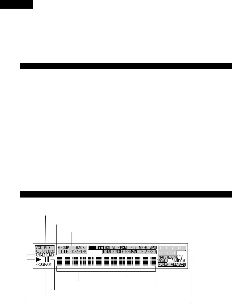
(3) Display
Lights during playback of multiple angles disc. |
|
|
|
|
|
|
|
|
|
|
|
|
Lights to indicate the currently playing audio |
||||||
|
|
|
|
|
|||||
Lights to indicate the currently playing disc. |
|
|
|
channel. |
|||||
|
|
|
L: |
Front left channel |
|||||
|
|
|
|
|
|||||
Lights when the audio signals can be down-mixed. |
|
|
|
C: |
Center channel |
||||
|
|
|
R: |
Front right channel |
|||||
|
|
|
|
|
|||||
These light to indicate the names of the sections of the disc being played. |
|
|
|
SL: |
Surround left channel |
||||
|
|
|
S: |
Mono surround channel |
|||||
|
|
|
|
|
|||||
Lights to indicate the currently playing audio format. |
|
|
|
SR: Surround right channel |
|||||
|
|
|
LFE: Low frequency effect |
||||||
|
|
|
|
|
|
|
|
|
|
|
|
|
|
|
|
|
|
|
|
|
|
|
|
|
|
|
|
|
|
|
|
|
|
|
|
|
|
|
|
Lights to indicate the
currently playing video
type.
F: Film source
V: Video source
These light to indicate the time display mode.
Displays the title, track number and elapsed time during playback.
Lights in the still/pause mode.
Lights when progressive video signals are being output.
Lights in the programmed play mode.
Lights during playback, flashes when the resume play memory function is activated.
Lights in the repeat play mode.
Lights in the random play mode.
20
ENGLISH
6 REMOTE CONTROL UNIT
2 The DVD-5900 can be controlled from a distance using the included remote control unit (RC-962).
(1) Inserting Batteries
q Remove the remote control unit’s rear cover.
wPlace two R6P/AA batteries in the battery compartment in the direction indicated by the marks.
e Close the rear cover.
Cautions On Batteries
•Use R6P/AA batteries in this remote control unit.
•Replace the batteries with new ones approximately once a year, though this depends on the frequency with which the remote control unit is used.
•If the remote control unit does not operate from close to the main unit, replace the batteries with new ones, even if less than a year has passed.
•The included battery is only for verifying operation. Replace it with a new battery as soon as possible.
•When inserting the batteries, be careful to do so in the proper direction, following the <and >marks in the remote control unit’s battery compartment.
•To prevent damage or battery fluid leakage:
•Do not use a new battery with an old one.
•Do not use two different types of batteries.
•Do not short-circuit, disassemble, heat or dispose of batteries in flames.
•Remove the batteries when not planning to use the remote control unit for a long period of time.
•If the batteries should leak, carefully wipe off the fluid from the inside of the battery compartment, then insert new batteries.
(2) Using the Remote Control Unit
Approx. 7 meters
30°
30° 
•When operating the remote control unit, point it at the remote control sensor as shown on the diagram.
•The remote control unit can be used from a direct distance of approximately 7 meters. This distance will be shorter, however, if there are obstacles in the way or if the remote control unit is not pointed directly at the remote control sensor.
•The remote control unit can be operated at a horizontal angle of up to 30° with respect to the remote control sensor.
NOTES:
•It may be difficult to operate the remote control unit if the remote control sensor is exposed to direct sunlight or strong artificial light.
•Do not press buttons on the main unit and on the remote control unit at the same time. Doing so will result in malfunction.
21

ENGLISH
(3) Names and Functions of Remote Control Unit Buttons
2 Button not explained here function in the same way as the corresponding buttons on the main unit.
POWER ON/POWER OFF buttons
Press this to switch the power between on and standby.
Number buttons
Use these to input numbers.
Use the +10 button to input numbers of 10 or over.
Example: To input 25
+10  +10
+10  5
5
TOP MENU button
The top menu stored on the disc is displayed.
Cursor buttons/ENTER button
Use the •and ªcursor buttons to select in the vertical direction.
Use the 0and 1cursor buttons to select in the horizontal direction.
Press the ENTER button to select the item selected with the cursor buttons.
MENU button
The DVD menu stored on the disc is displayed.
STOP button (2)
SKIP buttons
ANGLE button
Press this to switch the angle.
POWER |
NTSC / PAL |
OPEN / |
|
CLOSE |
|||
ON |
OFF |
|
|
|
|
|
PROG / DIR |
1 |
2 |
3 |
|
|
|
|
CLEAR |
4 |
5 |
6 |
|
|
|
|
SRS.TS |
7 |
8 |
9 |
|
|
|
CALL |
RETURN |
0 |
+10 |
|
|
TOP MENU |
|
|
DISPLAY |
T. MENU |
|
|
DISP. |
|
ENTER |
|
|
|
|
|
PLAY |
MENU |
|
STILL / |
|
|
STOP |
|
|
|
PAUSE |
|
|
|
|
|
|
SKIP |
SLOW / SEARCH |
||
ANGLE |
SUBTITLE |
AUDIO SEARCH MODE |
|
NTSC/PAL button
Use this to switch the set’s video output format (NTSC/PAL).
OPEN/CLOSE button
PROGRAM/DIRECT button (PROG/DIR)
Press this to switch between the normal play, programmed play.
CLEAR button
Press this to clear numbers that you have input.
SRS.TS button
Sets the virtual surround sound. (Functions when playing DVD-videos or VCDs only. (See page 46.))
RETURN button
Press this to return to the previous menu screen.
DISPLAY button
Press this to display the ON-SCREEN.
CALL button
Press this to check the program contents.
PLAY button (1)
STILL/PAUSE button (3)
SLOW/SEARCH buttons
SUBTITLE button
Press this to switch the DVD’s subtitle language.
A-B repeat button (A-B)
Use this to repeat sections between two specific points.
REPEAT button
Press this to play tracks repeatedly.
SETUP button
Press this to display the default setting screen.
DIMMER button
Use this to adjust the brightness of the main unit’s display. Can be switched in 4 steps, from OFF to always on.
ZOOM button
Press this to enlarge the image.
Picture adjust button (PIC.ADJ)
Press this to adjust the picture quality to suit your tastes.
REPEAT |
A-B |
RANDOM MARKER |
SETUP |
DIMMER |
PIC.ADJ |
|
ZOOM |
PAGE |
RC-962
SEARCH MODE button
Press this to change the search mode to search for groups or titles, tracks or chapters when selecting sections of discs directly using the number buttons.
AUDIO button
For DVDs, press this to switch the audio language. For video CDs, press this to switch the channel between “LR”, “L” and “R”.
RANDOM button
Press this to play the tracks on the video or music CD in random order.
MARKER button
Press this to mark places you want to see again.
PAGE -/PAGE + buttons
Use these to selected the desired still picture on DVD audio discs containing browseable still pictures.
22
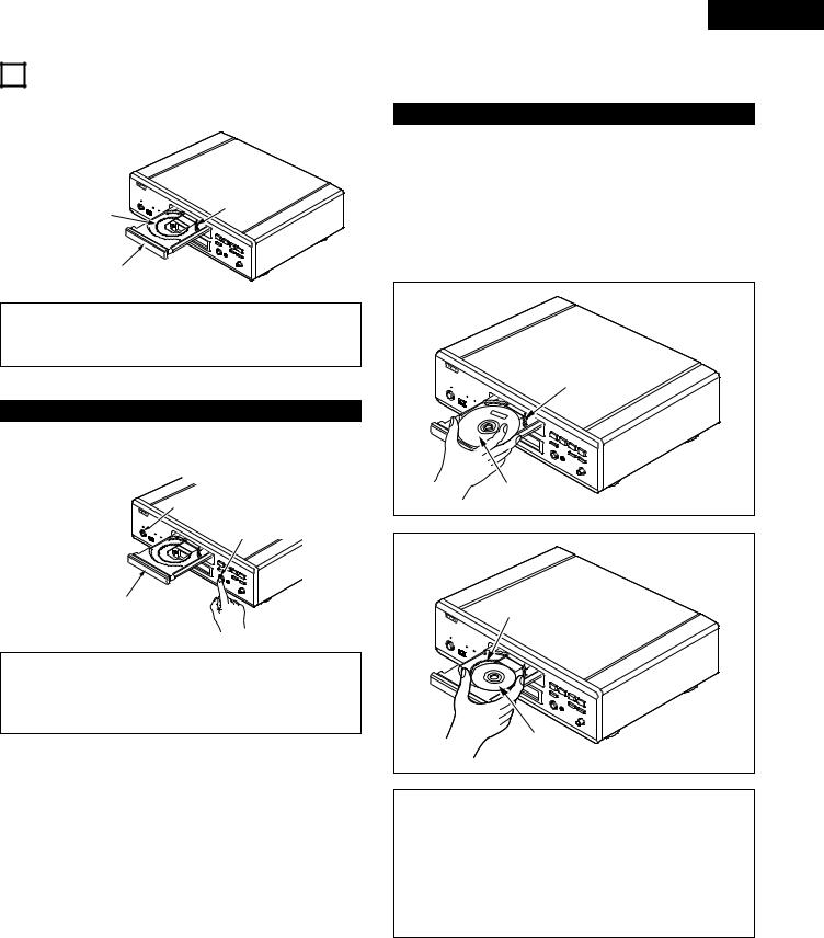
7 LOADING DISCS
2 Set discs in the disc tray with the labeled (printed) side facing up.
12 cm disc guide
8 cm disc guide
Disc tray
NOTE:
•Do not move the DVD-5900 while a disc is playing. Doing so may scratch the disc.
(1) Opening and Closing the Disc Tray
q Turn on the power.
w Press the OPEN/CLOSE button.
Power button
OPEN/CLOSE button
Disc tray
NOTES:
•Be sure to turn on the power before opening and closing the disc tray.
•Do not strike on the button with a pencil, etc.
ENGLISH
(2)Loading Discs
•Pick up the disc carefully so as not to touch the signal surface and hold it with the labeled side facing up.
•With the disc tray fully open, set the disc in the disc tray.
•Set 12 cm discs in the outer tray guide (Figure 1), 8 cm discs in the inner tray guide (Figure 2).
•Press the OPEN/CLOSE button. The disc is automatically loaded.
•The disc tray can also be closed automatically to load the disc by pressing the PLAY button.
Figure 1 |
Outer disc tray |
12 cm disc |
Figure 2 |
Inner disc tray |
8 cm disc |
NOTES:
•If a foreign object is caught in the disc tray during closing, simply press the OPEN/CLOSE button again and the tray will open.
•Do not press the disc tray in by hand when the power is off. Doing so will damage it.
•Do not place foreign objects in the disc tray. Doing so will damage it.
23
ENGLISH
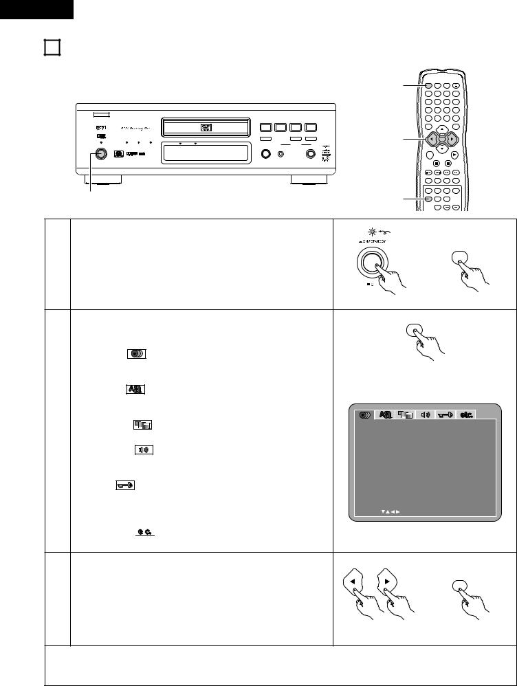
8 CHANGING THE DEFAULT SETTINGS
2Make the initial settings to suit your usage conditions before starting playback.
The initial settings are retained until they are next changed, even if the power is turned off.
B
|
|
|
|
PLAY |
STOP |
|
|
|
|
|
|
1 |
2 |
8 |
9 |
|
|
|
|
STILL / PAUSE |
|
|
|
AL24 PLUS |
DENON LINK |
IEEE 1394 |
|
3 |
|
6 |
7 |
POWER |
|
SUPER AUDIO CD |
DVI |
OPEN / CLOSE |
|
MODE SET UP |
|
|
|
|
|
|
|||
|
|
|
|
5 |
MODE |
|
SELECT |
¢ON / STANDBY |
|
|
|
|
|
||
£OFF |
|
|
|
|
|
|
PUSH ENTER |
DVD AUDIO-VIDEO / SUPER AUDIO CD PLAYER DVD-5900
REMOTE SENSOR
1
3
POWER |
NTSC / PAL |
OPEN / |
|
CLOSE |
|||
ON |
OFF |
|
|
|
|
|
PROG / DIR |
1 |
2 |
3 |
|
|
|
|
CLEAR |
4 |
5 |
6 |
|
|
|
|
SRS.TS |
7 |
8 |
9 |
|
|
|
CALL |
RETURN |
0 |
+10 |
|
|
TOP MENU |
|
|
DISPLAY |
T. MENU |
|
|
DISP. |
|
ENTER |
|
|
|
|
|
PLAY |
MENU |
|
STILL / |
|
|
STOP |
|
|
|
PAUSE |
|
|
|
|
|
SKIP |
SLOW / SEARCH |
|
|
|
|
ANGLE |
SUBTITLE AUDIO SEARCH MODE |
|
|
|
|
REPEAT |
A-B |
RANDOM MARKER |
|
1 |
2 |
SETUP |
DIMMER PIC.ADJ |
|
|
|
ZOOM |
PAGE |
||
|
|
Light |
|
|
|
|
Turn on the power. |
|
|
|
POWER |
1 |
|
|
|
ON |
|
• Press the power button, the power indicator lights and the power turns |
|
|
|
||
|
|
|
|
||
|
|
|
|
|
|
|
on. |
|
|
|
|
|
|
Main unit |
|
|
Remote control unit |
|
In the stop mode, press the SETUP button. |
|
SETUP |
|
|
|
• The setup (default settings) screen appears. |
|
|
|
|
|
NOTE: For some menus, the initial values can be changed during playback. |
|
|
|
|
|
DISC SETUP |
|
|
|
|
|
Use this to set the language to be used when playing the disc. If the set |
Remote control unit |
|||
|
language is not offered on that disc, the discs default language is set. |
||||
|
|
|
|
|
|
|
OSD SETUP |
|
|
|
|
|
Use this to set the language for the default setting screen and messages |
|
|
|
|
|
displayed on the TV screen (“PLAY”, etc.). |
|
|
|
|
2 |
VIDEO SETUP |
D I SC SE TUP |
|
|
|
Use this to set the DVD-5900’s screen mode. (TV aspect and TV type.) |
D I AL OG |
|
|
ENGL I SH |
|
SUBT I TL E |
|
|
OF F |
||
|
AUDIO SETUP |
|
|
||
|
D I SC MENUS |
|
|
ENGL I SH |
|
|
Use this to set the DVD-5900’s audio output mode. |
E X I T SE TUP |
|
|
|
|
(Digital and LPCM output settings.) |
|
|
|
|
|
|
|
|
|
|
|
RATINGS |
|
|
|
|
|
Use this to disable playback of adult DVDs so that children cannot watch |
|
|
|
|
|
them. Note that playback of adult DVDs cannot be disabled if the rating |
SE L ECT : |
DEC I S I ON : ENTER BUT TON |
||
|
level is not recorded on the DVD. |
||||
|
|
|
|
|
|
OTHER SETUP 
These include special settings CAPTIONS and COMPRESSION.
|
Use the 0and 1cursor buttons to select the desired setting item, then |
|
|
|
press the ENTER button. |
|
|
|
Select “DISC SETUP”. (See page 26.) |
|
ENTER |
|
Select “OSD SETUP”. (See page 29.) |
|
|
3 |
|
|
|
Select “VIDEO SETUP”. (See page 30.) |
|
|
|
|
Select “AUDIO SETUP”. (See page 33.) |
|
|
|
Select “RATINGS”. (See page 38.) |
Remote control unit |
Remote control unit |
|
Select “OTHER SETUP”. (See page 40.) |
|
|
To exit the setup mode
Use the ªcursor button to select “EXIT SETUP”, then press the ENTER button. It is also possible to quit by pressing the SETUP button on the remote control unit.
24
ENGLISH
Setup items for use
Bold characters indicate factory defaults.
DISC SETUP |
|
|
RATINGS |
|
|
|
|
|
DIALOG |
ENGLISH |
RATING LEVEL |
0(LOCK ALL) |
|||||
|
|
|
FRENCH |
|
|
|
1 |
|
|
|
|
SPANISH |
|
|
|
2 |
|
|
|
|
GERMAN |
|
|
|
3 |
|
|
|
|
JAPANESE |
|
|
|
4 |
|
|
|
|
OTHERS |
|
|
|
5 |
|
|
|
|
|
|
|
|
6 |
|
SUBTITLE |
OFF |
|
|
|
7 |
|
||
|
|
|
ENGLISH |
|
|
|
8(NO LIMIT) |
|
|
|
|
FRENCH |
PASSWORD |
CHANGE |
OLD PASSWORD |
||
|
|
|
SPANISH |
|||||
|
|
|
GERMAN |
|
|
|
|
NEW PASSWORD |
|
|
|
JAPANESE |
|
|
|
|
COMFIRM PASSWORD |
|
|
|
OTHERS |
|
|
|
|
|
|
|
|
|
OTHER SETUP |
|
|
|
|
DISC MENUS |
ENGLISH |
PLAYER MODE |
AUDIO |
|||||
|
|
|
FRENCH |
|
|
|
VIDEO |
|
|
|
|
SPANISH |
CAPTIONS |
OFF |
|
||
|
|
|
GERMAN |
|
||||
|
|
|
JAPANESE |
|
|
|
ON |
|
|
|
|
OTHERS |
|
|
|
|
|
OSD SETUP |
|
|
COMPRESSION |
OFF |
|
|||
|
|
|
||||||
OSD LANGUAGE |
ENGLISH |
|
||||||
|
|
|
ON |
|
||||
|
|
|
FRANÇAIS |
|
|
|
|
|
|
|
|
|
|
|
|
|
|
|
|
|
ESPAÑOL |
AUTO POWER |
OFF |
|
||
|
|
|
|
|
||||
WALL PAPER |
BLUE |
MODE |
ON |
|
||||
|
|
|
|
|
||||
|
|
|
GRAY |
SLIDE SHOW |
5 SEC |
|
||
|
|
|
BLACK |
|
||||
|
|
|
|
|
|
|
|
|
PICTURE
|
|
DISPLAY |
OFF |
|
||
|
|
|
|
|
ON |
|
|
|
|
|
|
|
|
VIDEO SETUP |
|
|
||||
|
|
TV ASPECT |
4:3 PS |
|
||
|
|
|
|
|
4:3 LB |
|
|
|
|
|
|
WIDE (16:9) |
|
|
|
TV TYPE |
NTSC |
|
||
|
|
|
|
|
PAL |
|
|
|
|
|
|
MULTI |
|
|
|
VIDEO OUT |
PROGRESSIVE |
|||
|
|
|
|
|
INTERLACED |
|
|
|
PROGRESSIVE |
AUTO1 |
|
||
|
|
MODE |
AUTO2 |
|
||
|
|
|
|
|
VIDEO1 |
|
|
|
|
|
|
VIDEO2 |
|
|
|
|
|
|
VIDEO3 |
|
|
|
PICTURE SIZE |
OFF |
|
||
|
|
|
|
|
SQUEEZE |
|
|
|
|
|
|
ZOOM |
|
|
|
|
|
|
|
|
AUDIO SETUP |
CHANNEL |
MULTI CHANNEL |
||||
|
|
AUDIO |
||||
|
|
|
|
|
2 CHANNEL |
|
|
|
DIGITAL OUT |
NORMAL |
|
||
|
|
|
|
|
PCM |
|
|
|
LPCM |
OFF |
|
||
|
|
(44.1 kHz/48 kHz) |
ON |
|
||
|
|
DENON LINK |
OFF |
|
||
|
|
|
|
|
2nd |
|
|
|
IEEE1394 |
OFF |
AUTO PLAY |
||
|
|
|
|
|
ON |
|
|
|
SOURCE DIRECT |
OFF |
AUDIO FORMAT |
||
|
|
|||||
|
|
|
|
|
ON |
|
|
|
BASS ENHANCER |
OFF |
|
||
|
|
|
|
|
ON |
|
SPEAKER |
FRONT SP |
LARGE |
CONFIGURATION |
CENTER SP |
SMALL |
|
LARGE |
|
|
|
SMALL |
|
SUBWOOFER |
NONE |
|
YES |
|
|
SURROUND SP |
NO |
|
LARGE |
|
|
|
SMALL |
|
|
NONE |
|
CROSSOVER |
40Hz |
|
|
60Hz |
|
|
80Hz |
|
|
100Hz |
|
|
120Hz |
CHANNEL LEVEL |
TEST TONE |
OFF |
|
|
AUTO |
|
|
MANUAL |
|
FRONT Lch |
0 dB |
|
CENTER |
0 dB |
|
FRONT Rch |
0 dB |
|
SURROUND Rch |
0 dB |
|
SURROUND Lch |
0 dB |
|
SUBWOOFER |
0 dB |
|
SW+10dB |
OFF |
|
|
ON |
DELAY TIME |
DISTANCE |
METERS |
|
|
FEET |
|
FRONT Lch |
12 ft |
|
FRONT Rch |
12 ft |
|
CENTER |
12 ft |
|
SURROUND Lch |
10 ft |
|
SURROUND Rch |
10 ft |
|
SUBWOOFER |
12 ft |
|
DEFAULT |
ON |
OFF |
|
|
ON |
|
|
FORMAT1 |
|
|
FORMAT2 |
|
|
25
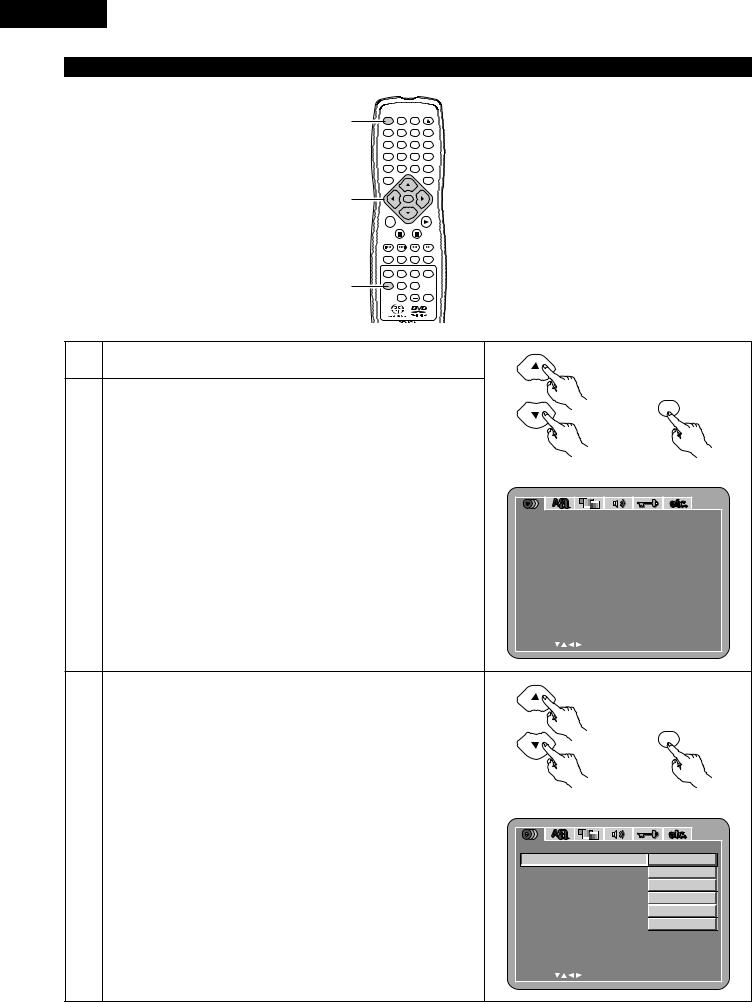
ENGLISH
When “DISC SETUP” is selected
1
|
POWER |
OPEN / |
|
NTSC / PAL CLOSE |
|
ON |
OFF |
|
|
|
PROG / DIR |
1 |
2 |
3 |
|
|
CLEAR |
4 |
5 |
6 |
SRS.TS
7 |
8 |
9 |
|
|
CALL RETURN |
0 |
+10 |
|
TOP MENU |
|
DISPLAY |
T. MENU |
|
DISP. |
1, 2, 3 |
|
ENTER |
|
|
|
|
|
|
PLAY |
|
MENU |
|
STILL / |
|
|
|
STOP |
|
|
|
|
PAUSE |
||
|
SKIP |
SLOW / SEARCH |
||
|
ANGLE |
SUBTITLE |
AUDIO |
SEARCH MODE |
|
REPEAT |
A-B |
RANDOM |
MARKER |
1 |
SETUP |
DIMMER |
PIC.ADJ |
|
|
ZOOM |
PAGE |
||
1 |
See page 24. |
|
|
|
|
|
|
|
|
|
ENTER |
|
Use the •and ªcursor buttons to select the desired setting, then press |
|
|
|
the ENTER button. |
Remote control unit |
Remote control unit |
|
DIALOG |
|
|
2 |
Use this to set the language of the sound output from the speakers. |
D I SC SE TUP |
|
|
|
||
SUBTITLE |
D I AL OG |
ENGL I SH |
|
|
Use this to set the language of the subtitles displayed on the TV. |
SUBT I TL E |
OF F |
|
|
D I SC MENUS |
ENGL I SH |
|
DISC MENUS |
|
|
|
Use this to set the language of the menus recorded on the disc (top menu, |
E X I T SE TUP |
|
|
etc.). |
|
|
|
|
SE L ECT : |
DEC I S I ON : ENTER BUT TON |
Use the •and ªcursor buttons to select the desired setting, then press
the ENTER button.
ENTER
q When “DIALOG” is selected:
ENGLISH (Factory default)
Select this when you want to play the DVD with the sound in English.
|
FRENCH |
Remote control unit |
Remote control unit |
3 |
Select this when you want to play the DVD with the sound in French. |
|
|
SPANISH |
|
|
|
Select this when you want to play the DVD with the sound in Spanish. |
D I SC SE TUP |
|
|
|
GERMAN |
D I AL OG |
ENGL I SH |
|
SUBT I TL E |
F RENCH |
|
|
Select this when you want to play the DVD with the sound in German. |
||
|
D I SC MENUS |
SPANI SH |
|
|
JAPANESE |
||
|
|
GERMAN |
|
|
Select this when you want to play the DVD with the sound in Japanese. |
|
|
|
E X I T SE TUP |
JAPANESE |
|
|
OTHERS |
|
OTHERS |
|
Use the number buttons to input the language number. |
|
|
|
(See “Language code list” on page 28.) |
|
|
|
|
SE L ECT : |
DEC I S I ON : ENTER BUT TON |
26
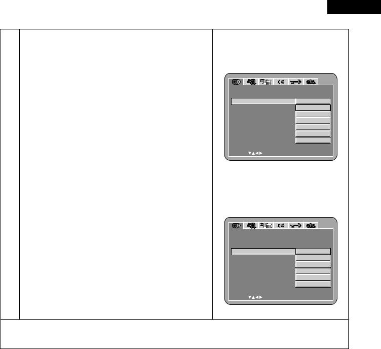
ENGLISH
wWhen “SUBTITLE” is selected:
OFF (Factory default)
Select this if you do not want to display the subtitles. (For some discs it is not possible to turn off the subtitle display.)
ENGLISH
Select this when you want to play the DVD with the subtitles in English.
FRENCH
Select this when you want to play the DVD with the subtitles in French.
SPANISH
Select this when you want to play the DVD with the subtitles in Spanish.
GERMAN
Select this when you want to play the DVD with the subtitles in
|
German. |
|
JAPANESE |
3 |
Select this when you want to play the DVD with the subtitles in |
Japanese. |
|
|
OTHERS |
|
Use the number buttons to input the language number. |
|
(See “Language code list” on page 28.) |
eWhen “DISC MENUS” is selected:
ENGLISH (Factory default)
Select this when you want to display the menus in English.
FRENCH
Select this when you want to display the menus in French.
SPANISH
Select this when you want to display the menus in Spanish.
GERMAN
Select this when you want to display the menus in German.
JAPANESE
Select this when you want to display the menus in Japanese.
OTHERS
Use the number buttons to input the language number. (See “Language code list” on page 28.)
D I SC SE TUP |
|
D I AL OG |
|
SUBT I TL E |
OF F |
D I SC MENUS |
ENGL I SH |
|
F RENCH |
E X I T SE TUP |
SPANI SH |
|
GERMAN |
|
JAPANESE |
|
OTHERS |
SE L ECT : |
DEC I S I ON : ENTER BUT TON |
D I SC SE TUP |
|
D I AL OG |
|
SUBT I TL E |
|
D I SC MENUS |
ENGL I SH |
|
F RENCH |
E X I T SE TUP |
SPANI SH |
|
GERMAN |
|
JAPANESE |
|
OTHERS |
SE L ECT : |
DEC I S I ON : ENTER BUT TON |
To exit the setup mode
Use the ªcursor button to select “EXIT SETUP”, then press the ENTER button. It is also possible to quit by pressing the SETUP button on the remote control unit.
27

ENGLISH
Language code list
Code |
Language |
Code |
Language |
Code |
Language |
Code |
Language |
|
|
|
|
|
|
|
|
6565 |
Afar |
7079 |
Faroese |
7678 |
Lingala |
8375 |
Slovak |
|
|
|
|
|
|
|
|
6566 |
Abkhazian |
7082 |
French |
7679 |
Laothian |
8376 |
Slovenian |
|
|
|
|
|
|
|
|
6570 |
Afrikaans |
7089 |
Frisian |
7684 |
Lithuanian |
8377 |
Samoan |
|
|
|
|
|
|
|
|
6577 |
Ameharic |
7165 |
Irish |
7686 |
Latvian, Lettish |
8378 |
Shona |
|
|
|
|
|
|
|
|
6582 |
Arabic |
7168 |
Scots Gaelic |
7771 |
Malagasy |
8379 |
Somali |
|
|
|
|
|
|
|
|
6583 |
Assamese |
7176 |
Galician |
7773 |
Maori |
8381 |
Albanian |
|
|
|
|
|
|
|
|
6588 |
Aymara |
7178 |
Guarani |
7775 |
Macedonish |
8382 |
Serbian |
|
|
|
|
|
|
|
|
6590 |
Azerbaijani |
7185 |
Gujarati |
7776 |
Malayalam |
8385 |
Sundanese |
|
|
|
|
|
|
|
|
6665 |
Bashkir |
7265 |
Hausa |
7778 |
Mongolian |
8386 |
Swedish |
|
|
|
|
|
|
|
|
6669 |
Byelorussian |
7273 |
Hindi |
7779 |
Moldavian |
8387 |
Swahili |
|
|
|
|
|
|
|
|
6671 |
Bulgarian |
7282 |
Croatian |
7782 |
Marathi |
8465 |
Tamil |
|
|
|
|
|
|
|
|
6672 |
Bihari |
7285 |
Hungarian |
7783 |
Malay |
8469 |
Telugu |
|
|
|
|
|
|
|
|
6678 |
Bengali; Bangla |
7289 |
Armenian |
7784 |
Maltese |
8471 |
Tajik |
|
|
|
|
|
|
|
|
6679 |
Tibetan |
7365 |
Interlingua |
7789 |
Burmese |
8472 |
Thai |
|
|
|
|
|
|
|
|
6682 |
Breton |
7378 |
Indonesian |
7865 |
Nauru |
8473 |
Tigrinya |
|
|
|
|
|
|
|
|
6765 |
Catalan |
7383 |
Icelandic |
7869 |
Nepali |
8475 |
Turkmen |
|
|
|
|
|
|
|
|
6779 |
Corsican |
7384 |
Italian |
7876 |
Dutch |
8476 |
Tagalog |
|
|
|
|
|
|
|
|
6783 |
Czech |
7387 |
Hebrew |
7879 |
Norwegian |
8479 |
Tonga |
|
|
|
|
|
|
|
|
6789 |
Welsh |
7465 |
Japanese |
7982 |
Oriya |
8482 |
Turkish |
|
|
|
|
|
|
|
|
6865 |
Danish |
7473 |
Yiddish |
8065 |
Panjabi |
8484 |
Tatar |
|
|
|
|
|
|
|
|
6869 |
German |
7487 |
Javanese |
8076 |
Polish |
8487 |
Twi |
|
|
|
|
|
|
|
|
6890 |
Bhutani |
7565 |
Georgian |
8083 |
Pashto, Pushto |
8575 |
Ukrainian |
|
|
|
|
|
|
|
|
6976 |
Greek |
7575 |
Kazakh |
8084 |
Portuguese |
8582 |
Urdu |
|
|
|
|
|
|
|
|
6978 |
English |
7576 |
Greenlandic |
8185 |
Quechua |
8590 |
Uzbek |
|
|
|
|
|
|
|
|
6979 |
Esperanto |
7577 |
Cambodian |
8277 |
Rhaeto-Romance |
8673 |
Vietnamese |
|
|
|
|
|
|
|
|
6983 |
Spanish |
7578 |
Kannada |
8279 |
Romanian |
8679 |
Volapük |
|
|
|
|
|
|
|
|
6984 |
Estonian |
7579 |
Korean |
8285 |
Russian |
8779 |
Wolof |
|
|
|
|
|
|
|
|
6985 |
Basque |
7583 |
Kashmiri |
8365 |
Sanskrit |
8872 |
Xhosa |
|
|
|
|
|
|
|
|
7065 |
Persian |
7585 |
Kurdish |
8368 |
Sindhi |
8979 |
Yoruba |
|
|
|
|
|
|
|
|
7073 |
Finnish |
7589 |
Kirghiz |
8372 |
Serbo-Croatian |
9072 |
Chinese |
|
|
|
|
|
|
|
|
7074 |
Fiji |
7665 |
Latin |
8373 |
Singhalese |
9085 |
Zulu |
|
|
|
|
|
|
|
|
28
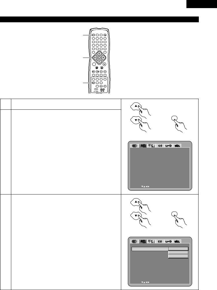
When “OSD SETUP” is selected
1
1, 2, 3
1
ENGLISH
POWER |
NTSC / PAL |
OPEN / |
|
CLOSE |
|||
ON |
OFF |
|
|
|
|
|
PROG / DIR |
1 |
2 |
3 |
|
|
|
|
CLEAR |
4 |
5 |
6 |
|
|
|
|
SRS.TS |
7 |
8 |
9 |
|
|
|
CALL |
RETURN |
0 |
+10 |
|
|
TOP MENU |
|
|
DISPLAY |
T. MENU |
|
|
DISP. |
|
ENTER |
|
|
|
|
|
PLAY |
MENU |
|
STILL / |
|
|
STOP |
|
|
|
PAUSE |
|
|
SKIP |
SLOW / SEARCH |
||
ANGLE |
SUBTITLE |
AUDIO SEARCH MODE |
|
REPEAT |
A-B |
RANDOM |
MARKER |
SETUP |
DIMMER |
PIC.ADJ |
|
|
ZOOM |
PAGE |
|
1 |
See page 24. |
|
|
|
|
|
|
|
|
|
|
|
Use the •and ªcursor buttons to select the desired setting, then press |
|
|
|
|
|
the ENTER button. |
|
|
|
ENTER |
|
|
|
|
|
|
|
OSD LANGUAGE |
|
|
|
|
|
Use this to set the language for the default setting screen and messages |
|
|
|
|
|
displayed on the TV screen (“PLAY”, etc.) |
|
Remote control unit |
Remote control unit |
|
|
WALL PAPER |
|
|
|
|
|
Use this to select the image to be shown on the screen in the stop mode |
|
|
|
|
2 |
and CD play mode. |
|
OSD SE TUP |
|
|
|
OSD |
L ANGUAGE |
ENGL I SH |
||
|
|
||||
|
|
|
|||
|
DISPLAY |
|
WAL L |
PAPER |
BUL E |
|
The DIMMER button permits the setting of whether or not there will be |
DIS P L A Y |
OF F |
||
|
|
|
|
||
|
an indication on the display of this unit only for |
the 2 seconds |
E X I T |
SE TUP |
|
|
immediately following the operation, even while the display has been |
|
|||
|
|
|
|
||
|
off. |
|
|
|
|
|
|
|
SE L ECT : |
DEC I S I ON : ENTER BUT TON |
|
|
|
|
|
ENTER |
|
Use the •and ªcursor buttons to select the desired setting, then press |
|
|
|
|
the ENTER button. |
Remote control unit |
Remote control unit |
|
|
q When “OSD LANGUAGE” is selected: |
|||
|
|
|
|
|
3 |
ENGLISH (Factory default) |
|
|
|
Select this to set the OSD language to English. |
OSD SE TUP |
|
||
|
FRANÇAIS |
OSD |
L ANGUAGE |
ENGL I SH |
|
Select this to set the OSD language to French. |
WAL L |
PAPER |
F RANÇA I S |
|
ESPAÑOL |
DIS P L A Y |
E SPAÑOL |
|
|
Select this to set the OSD language to Spanish. |
E X I T |
SE TUP |
|
|
|
|
||
|
|
SE L ECT : |
DEC I S I ON : ENTER BUT TON |
|
29
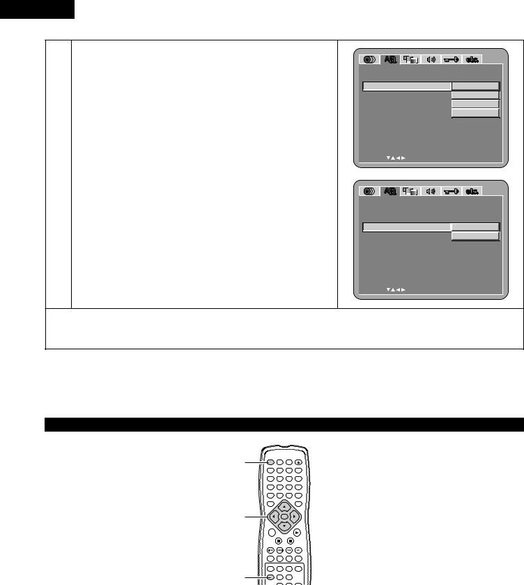
ENGLISH
wWhen “WALL PAPER” is selected:
BLUE (Factory default)
Select this to display a blue background on the TV display.
GRAY
Select this to display a gray background on the TV display.
BLACK
Select this to display a black background on the TV display.
PICTURE
Select this to display the wallpaper on the TV display.
3
eWhen “DISPLAY” is selected:
OFF (Factory default)
This is valid when the display has been switched off with the DIMMER button. The display will not show an indication even when the button (ex. skip, stop, etc.) has been pressed.
ON
This is valid when the display has been switched off with the DIMMER button. When the button (ex. skip, stop, etc.) is pressed, the indication will appear on the display for approximately 2 seconds.
OSD SE TUP |
|
OSD L ANGUAGE |
|
WAL L PAPE R |
BUL E |
DIS P L A Y |
GRAY |
|
BL ACK |
E X I T SE TUP |
P I C TURE |
SE L EC T : |
DE C I S I ON : ENT E R BUT TON |
OSD SE TUP |
|
|
OSD L ANGUAGE |
|
|
WAL L PAPE R |
|
|
D I S P L A Y |
|
OF F |
|
|
ON |
E X I T SE TUP |
|
|
SE L EC T : |
DE C I S I ON : ENT E R |
BUT TON |
To exit the setup mode
Use the ªcursor button to select “EXIT SETUP”, then press the ENTER button. It is also possible to quit by pressing the SETUP button on the remote control unit.
When “VIDEO SETUP” is selected
1
1, 2, 3
1
POWER |
NTSC / PAL |
OPEN / |
|
CLOSE |
|||
ON |
OFF |
|
|
|
|
|
PROG / DIR |
1 |
2 |
3 |
|
|
|
|
CLEAR |
4 |
5 |
6 |
|
|
|
|
SRS.TS |
7 |
8 |
9 |
|
|
|
CALL |
RETURN |
0 |
+10 |
|
|
TOP MENU |
|
|
DISPLAY |
T. MENU |
|
|
DISP. |
|
ENTER |
|
|
|
|
|
PLAY |
MENU |
|
STILL / |
|
|
STOP |
|
|
|
PAUSE |
|
|
SKIP |
SLOW / SEARCH |
||
ANGLE |
SUBTITLE |
AUDIO SEARCH MODE |
|
REPEAT |
A-B |
RANDOM |
MARKER |
SETUP |
DIMMER |
PIC.ADJ |
|
|
ZOOM |
PAGE |
|
30
 Loading...