


 Loading...
Installing S25N and S25V Systems
December 15, 2008 |
100-00061-02 |

Copyright 2008 Force10 Networks®
All rights reserved. Printed in the USA. December 2008.
Force10 Networks® reserves the right to change, modify, revise this publication without notice.
Trademarks
Force10 Networks® and E-Series® are registered trademarks of Force10 Networks, Inc. Force10, the Force10 logo, E1200, E600, E600i, E300, EtherScale, TeraScale, and FTOS are trademarks of Force10 Networks, Inc. All other brand and product names are registered trademarks or trademarks of their respective holders.
Statement of Conditions
In the interest of improving internal design, operational function, and/or reliability, Force10 Networks reserves the right to make changes to products described in this document without notice. Force10 Networks does not assume any liability that may occur due to the use or application of the product(s) described herein.
Note: The country-specific warnings and statements of compliance have been moved to “Agency Compliance” on page 42, in Chapter 6, “System Specifications,” on page 41.

Contents
Preface
About this Guide . . . . . . . . . . . . . . . . . . . . . . . . . . . . . . . . . . . . . . . . . . . . . . . . . . . . . . . . . . . . 5
Information Symbols and Warnings . . . . . . . . . . . . . . . . . . . . . . . . . . . . . . . . . . . . . . . . . . . . . . . . . . . 5
Related Publications . . . . . . . . . . . . . . . . . . . . . . . . . . . . . . . . . . . . . . . . . . . . . . . . . . . . . . . . . . . . . . 7
Chapter 1
System Overview . . . . . . . . . . . . . . . . . . . . . . . . . . . . . . . . . . . . . . . . . . . . . . . . . . . . . . . . . . . . 9
Equipment . . . . . . . . . . . . . . . . . . . . . . . . . . . . . . . . . . . . . . . . . . . . . . . . . . . . . . . . . . . . . . . . . . . . . |
10 |
Features . . . . . . . . . . . . . . . . . . . . . . . . . . . . . . . . . . . . . . . . . . . . . . . . . . . . . . . . . . . . . . . . . . . . . . |
.11 |
Ports . . . . . . . . . . . . . . . . . . . . . . . . . . . . . . . . . . . . . . . . . . . . . . . . . . . . . . . . . . . . . . . . . . . . . . . . . |
.11 |
System Status . . . . . . . . . . . . . . . . . . . . . . . . . . . . . . . . . . . . . . . . . . . . . . . . . . . . . . . . . . . . . . . . . . |
12 |
LED Displays . . . . . . . . . . . . . . . . . . . . . . . . . . . . . . . . . . . . . . . . . . . . . . . . . . . . . . . . . . . . . . . |
12 |
Chapter 2 |
|
Site Preparation . . . . . . . . . . . . . . . . . . . . . . . . . . . . . . . . . . . . . . . . . . . . . . . . . . . . . . . . . . . . |
15 |
Site Selection . . . . . . . . . . . . . . . . . . . . . . . . . . . . . . . . . . . . . . . . . . . . . . . . . . . . . . . . . . . . . . . . . . . |
15 |
Cabinet Placement . . . . . . . . . . . . . . . . . . . . . . . . . . . . . . . . . . . . . . . . . . . . . . . . . . . . . . . . . . . . . . |
16 |
Rack Mounting . . . . . . . . . . . . . . . . . . . . . . . . . . . . . . . . . . . . . . . . . . . . . . . . . . . . . . . . . . . . . . . . . . |
16 |
Fans and Airflow . . . . . . . . . . . . . . . . . . . . . . . . . . . . . . . . . . . . . . . . . . . . . . . . . . . . . . . . . . . . . . . . |
16 |
Power . . . . . . . . . . . . . . . . . . . . . . . . . . . . . . . . . . . . . . . . . . . . . . . . . . . . . . . . . . . . . . . . . . . . . . . . |
17 |
S25N . . . . . . . . . . . . . . . . . . . . . . . . . . . . . . . . . . . . . . . . . . . . . . . . . . . . . . . . . . . . . . . . . . . . . . |
17 |
S25V . . . . . . . . . . . . . . . . . . . . . . . . . . . . . . . . . . . . . . . . . . . . . . . . . . . . . . . . . . . . . . . . . . . . . . |
17 |
Power over Ethernet (PoE) Support . . . . . . . . . . . . . . . . . . . . . . . . . . . . . . . . . . . . . . . . . . . . . . |
17 |
Storing Components . . . . . . . . . . . . . . . . . . . . . . . . . . . . . . . . . . . . . . . . . . . . . . . . . . . . . . . . . . . . . |
18 |
Tools Required . . . . . . . . . . . . . . . . . . . . . . . . . . . . . . . . . . . . . . . . . . . . . . . . . . . . . . . . . . . . . . . . . |
18 |
Chapter 3 |
|
Installing the Switch . . . . . . . . . . . . . . . . . . . . . . . . . . . . . . . . . . . . . . . . . . . . . . . . . . . . . . . . |
19 |
Inserting Optional Modules (10-Gigabit or Stacking) . . . . . . . . . . . . . . . . . . . . . . . . . . . . . . . . . . . . . |
19 |
Installing the System on a Tabletop . . . . . . . . . . . . . . . . . . . . . . . . . . . . . . . . . . . . . . . . . . . . . . . . . . |
21 |
Installing the System in a Rack or Cabinet . . . . . . . . . . . . . . . . . . . . . . . . . . . . . . . . . . . . . . . . . . . . |
21 |
Two-Post Rack Mounting . . . . . . . . . . . . . . . . . . . . . . . . . . . . . . . . . . . . . . . . . . . . . . . . . . . . . . |
21 |
Four-Post Rack-mounting with Threaded Rails . . . . . . . . . . . . . . . . . . . . . . . . . . . . . . . . . . . . . |
22 |
Installing S25Nand S25V Systems |
3 |

Four-Post Rack-mounting with Cage Nuts . . . . . . . . . . . . . . . . . . . . . . . . . . . . . . . . . . . . . . . . . 23 Stacking . . . . . . . . . . . . . . . . . . . . . . . . . . . . . . . . . . . . . . . . . . . . . . . . . . . . . . . . . . . . . . . . . . . . . . . 26 Using FTOS Stacking Commands . . . . . . . . . . . . . . . . . . . . . . . . . . . . . . . . . . . . . . . . . . . . . . . 26 Connecting Stack Ports (optional) . . . . . . . . . . . . . . . . . . . . . . . . . . . . . . . . . . . . . . . . . . . . . . . . 27 Supplying Power . . . . . . . . . . . . . . . . . . . . . . . . . . . . . . . . . . . . . . . . . . . . . . . . . . . . . . . . . . . . . . . . 29 S25V . . . . . . . . . . . . . . . . . . . . . . . . . . . . . . . . . . . . . . . . . . . . . . . . . . . . . . . . . . . . . . . . . . . . . . 29
Chapter 4
Installing Backup Power . . . . . . . . . . . . . . . . . . . . . . . . . . . . . . . . . . . . . . . . . . . . . . . . . . . . . 31
Backup Power Components . . . . . . . . . . . . . . . . . . . . . . . . . . . . . . . . . . . . . . . . . . . . . . . . . . . . . . . 31 The Power Connections on the Switch . . . . . . . . . . . . . . . . . . . . . . . . . . . . . . . . . . . . . . . . . . . . . . . 32 Installing the Redundant DC Power Supply for the S25V . . . . . . . . . . . . . . . . . . . . . . . . . . . . . . . . . 33 Inserting Tandem PSUs into a Rack . . . . . . . . . . . . . . . . . . . . . . . . . . . . . . . . . . . . . . . . . . . . . . 34 Connecting the DC-to-DC Cable . . . . . . . . . . . . . . . . . . . . . . . . . . . . . . . . . . . . . . . . . . . . . . . . . 34
Chapter 5
Installing Ports . . . . . . . . . . . . . . . . . . . . . . . . . . . . . . . . . . . . . . . . . . . . . . . . . . . . . . . . . . . . . 37
Accessing the Console Port . . . . . . . . . . . . . . . . . . . . . . . . . . . . . . . . . . . . . . . . . . . . . . . . . . . . . . . |
37 |
Connecting S25V Ethernet Ports with PoE . . . . . . . . . . . . . . . . . . . . . . . . . . . . . . . . . . . . . . . . . . . . |
38 |
Installing Optics . . . . . . . . . . . . . . . . . . . . . . . . . . . . . . . . . . . . . . . . . . . . . . . . . . . . . . . . . . . . . . . . . |
39 |
Installing SFPs . . . . . . . . . . . . . . . . . . . . . . . . . . . . . . . . . . . . . . . . . . . . . . . . . . . . . . . . . . . . . . |
39 |
Installing XFPs . . . . . . . . . . . . . . . . . . . . . . . . . . . . . . . . . . . . . . . . . . . . . . . . . . . . . . . . . . . . . . |
40 |
Chapter 6
System Specifications. . . . . . . . . . . . . . . . . . . . . . . . . . . . . . . . . . . . . . . . . . . . . . . . . . . . . . . 41
Physical Design . . . . . . . . . . . . . . . . . . . . . . . . . . . . . . . . . . . . . . . . . . . . . . . . . . . . . . . . . . . . . . . . |
41 |
Environmental Parameters . . . . . . . . . . . . . . . . . . . . . . . . . . . . . . . . . . . . . . . . . . . . . . . . . . . . . . . . |
41 |
Power Requirements . . . . . . . . . . . . . . . . . . . . . . . . . . . . . . . . . . . . . . . . . . . . . . . . . . . . . . . . . . . . . |
42 |
Agency Compliance . . . . . . . . . . . . . . . . . . . . . . . . . . . . . . . . . . . . . . . . . . . . . . . . . . . . . . . . . . . . . . |
42 |
Safety Standards and Compliance Agency Certifications . . . . . . . . . . . . . . . . . . . . . . . . . . . . . . |
44 |
Electromagnetic Compatibility (EMC) . . . . . . . . . . . . . . . . . . . . . . . . . . . . . . . . . . . . . . . . . . . . . |
44 |
Product Recycling and Disposal . . . . . . . . . . . . . . . . . . . . . . . . . . . . . . . . . . . . . . . . . . . . . . . . . |
45 |
Appendix A
Technical Support . . . . . . . . . . . . . . . . . . . . . . . . . . . . . . . . . . . . . . . . . . . . . . . . . . . . . . . . . . 47
The iSupport Website . . . . . . . . . . . . . . . . . . . . . . . . . . . . . . . . . . . . . . . . . . . . . . . . . . . . . . . . . . . . |
47 |
Accessing iSupport Services . . . . . . . . . . . . . . . . . . . . . . . . . . . . . . . . . . . . . . . . . . . . . . . . . . . . |
48 |
Contacting the Technical Assistance Center . . . . . . . . . . . . . . . . . . . . . . . . . . . . . . . . . . . . . . . . . . . |
49 |
Locating Serial Numbers . . . . . . . . . . . . . . . . . . . . . . . . . . . . . . . . . . . . . . . . . . . . . . . . . . . . . . . . . . |
49 |
Requesting a Hardware Replacement . . . . . . . . . . . . . . . . . . . . . . . . . . . . . . . . . . . . . . . . . . . . . . . |
50 |
Index . . . . . . . . . . . . . . . . . . . . . . . . . . . . . . . . . . . . . . . . . . . . . . . . . . . . . . . . . . . . . . . . . . . . . 51
4
Preface |
About this Guide |
|
|
This guide provides site preparation recommendations, step-by-step procedures for rack mounting and desk mounting, inserting optional modules, and connecting to a power source.
After you have completed the hardware installation and power-up of the system, refer to the FTOS Configuration Guide for the S-Series for software configuration information and the FTOS Command Reference for the S-Series for detailed Command Line Interface (CLI) information, as detailed in Related Publications, below.
Information Symbols and Warnings
The following graphic symbols are used in this document to bring attention to hazards that exist when handling the system and its components. Please read these alerts and heed their warnings and cautions.
Table 1 describes symbols contained in this guide.
Table 1 Information Symbols
Symbol |
Warning |
Description |
||||
|
|
|
|
|
|
|
|
|
|
|
|
|
This symbol warns that improper handling and installation could result in bodily injury. |
|
|
|
|
|
Danger |
Before you begin work on this equipment, be aware of hazards involving electrical |
|
|
|
|
|
|
circuitry, networking environments, and instigate accident prevention procedures. |
|
|
|
|
|
|
|
|
|
|
|
|
Caution |
This symbol informs you that improper handling and installation could result in equipment |
|
|
|
|
|
damage or loss of data. |
|
|
|
|
|
|
|
|
|
|
|
|
|
|
|
|
|
|
|
|
Warning |
This symbol informs you that improper handling may reduce your component or system |
|
|
|
|
|
performance. |
|
|
|
|
|
|
|
|
|
|
|
|
|
|
|
|
|
|
|
|
Note |
This symbol informs you of important operational information. |
|
|
|
|
|
||
|
|
|
|
|
|
|
|
|
|
|
|
|
|
Danger: The installation of this equipment shall be performed by trained and qualified personnel only. Read this guide before installing and powering up this equipment. This equipment contains two power cords. Disconnect both power cords before servicing.
Installing S25N and S25V Systems |
5 |
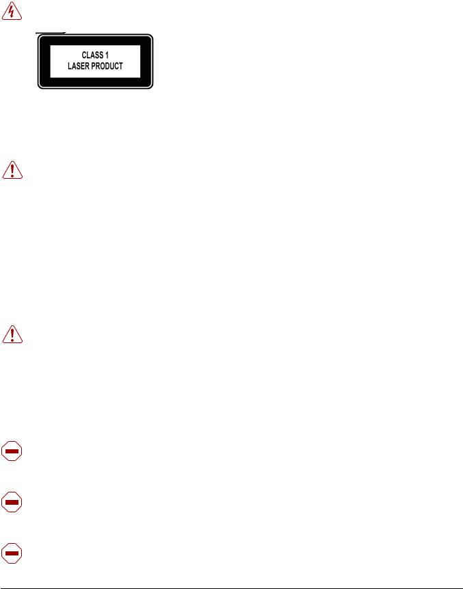
Danger: Class 1 laser product.
Attention: Produit laser de classe 1
Warnung: Laserprodukt der Klasse 1
This equipment contains optical transceivers, which comply with the limits of Class 1 laser radiation. Visible and invisible laser radiation may be emitted from the aperture of the optical transceiver ports when no cable is connected. Avoid exposure to laser radiation and do not stare into open apertures.
Warning: Building Supply Notice for AC Power Supply Use
This product relies on the building's installation for short-circuit (overcurrent) protection. Ensure that a fuse or circuit breaker no larger than 120 VAC, 15A U.S. (240 VAC, 10A international) is used on the phase conductors (all current-carrying conductors).
Attention: Pour ce qui est de la protection contre les courts-circuits (surtension), ce produit dépend de l'installation électrique du local. Vérifier qu'un fusible ou qu'un disjoncteur de 120 V alt., 15 A U.S. maximum (240 V alt., 10 A international) est utilisé sur les conducteurs de phase (conducteurs de charge).
Warnung: Dieses Produkt ist darauf angewiesen, daß im Gebäude ein Kurzschlußbzw. Überstromschutz installiert ist. Stellen Sie sicher, daß eine Sicherung oder ein Unterbrecher von nicht mehr als 240 V Wechselstrom, 10 A (bzw. in den USA 120 V Wechselstrom, 15 A) an den Phasenleitern (allen stromführenden Leitern) verwendet wird.
Warning: Building Supply Notice for DC Power Supply Use
An external disconnect must be provided and be easily accessible. Force10 Networks recommends the use of a 60A circuit breaker.
ATTENTION: Un interrupteur externe doit être fournis et doit être facilement accessible. Force10 Networks recommande l'utilisation d'un disjoncteur de 60Ampères.
WARNUNG: Eine leicht zugängliche Tren Force10 Networks nvorrichtung muss in der Verdrahtung eingebaut sein. Force10 Networks empfiehlt einen 60A Sicherungsautomaten zu benutzen.
Caution: Wear grounding wrist straps when handling this equipment to avoid ESD damage.
Caution: Earthing (AKA grounding) connection essential before connecting supply. Always make the ground connection first and disconnect it last.
Caution: Disposal of this equipment should be handled according to all national laws and regulations. See Product Recycling and Disposal on page 45.
6 |
About this Guide |
Caution: This unit has more than one power supply connection; all connections must be removed to remove all power from the unit.
ATTENTION: Cette unité est équipée de plusieurs raccordements d'alimentation. Pour supprimer tout courant électrique de l'unité, tous les cordons d'alimentation doivent être débranchés.
WARNUNG: Diese Einheit verfügt über mehr als einen Stromanschluß; um Strom gänzlich von der Einheit fernzuhalten, müssen alle Stromzufuhren abgetrennt sein.
Caution: Lithium Battery Notice
Danger of explosion if battery is replaced with incorrect type. Replace only with the same type recommended by the manufacturer. Dispose of used batteries according to the manufacturer's instructions.
ACHTUNG - Explosionsgefahr wenn die Battery in umgekehrter Polarität eingesetzt wird. Nur miteinem gleichen oder ähnlichen, vom Hersteller empfohlenen Typ, ersetzen. Verbrauchte Batterien müssen per den Instructionen des Herstellers verwertet werden.
ATTENTION - Il y a danger d'explosion s'il a remplacement incorrect de la batterie. Remplacer uniquement avec une batterie du meme type ou d'un type equivalent recommande par le constructeur. Mettre au rebut les batteries usagees conformement aux instructions du fabricant.
Note: Other cautionary statements appear in context elsewhere in this book.
Related Publications
The S25N and S25V run FTOS version 7.7.1.0 or greater. Refer to the following documents:
•FTOS Configuration Guide for the S-Series
•FTOS Command Reference for the S-Series
•S-Series and FTOS Release Notes
The FTOS Documentation CD-ROM contains the S-Series hardware guides and the FTOS files listed above. The CD-ROM also has:
•MIBs: Files for all SNMP MIBs supported by the software
•Data sheets: Links to Force10 product data sheets
•Security: Description and supporting files for setting up SSH, SSL, and HTTPS access to the switch
•Training: PDF files of the slide shows used in training
Note: Documentation CD-ROMs do not have software or Release Notes. For the most recent documentation and software, please visit iSupport (registration for access to some sections is required):
https://www.force10networks.com/CSPortal20/Main/SupportMain.aspx
The iSupport website also has a section for S-Series techtips and FAQs. For more information in this book on technical support, see Technical Support on page 39.
Installing S25N and S25V Systems |
7 |

8 |
About this Guide |
Chapter 1 |
System Overview |
|
|
The S25N (Cat# S25-01-GE-24T) and S25V (Cat# S25-01-GE-24V) models of the S-Series are high performance, low cost, stackable, Layer 2 switch/Layer 3 routers that support 24 built-in 10/100/1000 Base-T ports with four shared 1GbE SFP (small form-factor pluggable) ports, and two rear expansion slots that can host stacking ports or up to four 10GbE ports. The two differences between the two models are:
•The S25V supports Power over Ethernet (PoE) through its 24 copper ports (see Connecting S25V Ethernet Ports with PoE on page 38), while the S25N does not.
•The S25V has both AC (470W) and DC power inputs, while the S25N has two AC inputs (150W+150W). See Supplying Power on page 29. The S25V can also use the Force10 470W Redundant DC Power Supply (see Chapter 4, Installing Backup Power, on page 31) in current sharing (additive) mode.
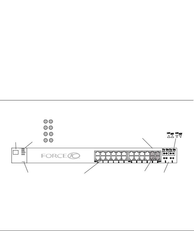
Figure 1 shows the front panel of the S25V. The S25N has almost the same layout, except that the catalog name differs, and an AC2 status LED replaces the DC status LED.
Figure 1 The S25V Front View
Status Panel
LEDs
|
|
OK |
Alarm |
Link/Active |
|
|
|
AC |
DC |
Indicator LEDs |
|
|
|
(SFP Ports 21-24) |
|||
Stack ID |
|
|
|||
XFP25 |
XFP27 |
|
|||
Indicator |
Catalog Name (S25-01-GE-24V) |
||||
|
|
||||
LED |
|
XFP26 |
XFP28 |
|
|
|
Alarm |
|
|
S25-01-GE-24V |
|
AC |
DC |
|
|
|
|
XFP25 |
27 |
|
|
|
|
XFP26 |
P28 |
|
|
|
|
STACK ID |
|
|
|
|
|
|
|
|
|
|
|
|
|
|
|
|
|
|
|
|
|
|
|
|
|
|
|
|
|
|
|
|
|
|
|
|
|
|
|
|
|
|
|
|
|
|
|
|
|
|
|
|
|
|
|
|
|
|
|
|
|
|
|
|
|
|
|
|
|
|
|
|
|
|
|
|
|
|
|
|
|
|
|
|
|
|
|
|
|
|
|
|
|
|
|
|
|
|
|
|
|
|
|
|
|
|
|
|
|
|
|
|
|
|
|
|
|
|
|
|
|
|
|
|
|
|
|
|
|
|
|
|
|
|
|
|
|
|
|
|
|
|
|
|
|
|
|
|
|
|
|
|
|
|
|
|
|
|
|
|
|
|
|
|
|
|
|
|
|
|
|
|
|
|
|
|
|
|
|
|
|
|
Shared |
|
|
|
|
|
|
|
|
|
|
||||||||||||||||
|
|
|
|
|
|
|
|
|
|
|
|
|
|
|
|
|
|
|
|
|
|
|
|
|
|
|
|
|
|
|
|
|
|
|||||||||||||||||
RJ-45 Console Port |
Ethernet Ports (10/100/1000) |
10/100/1000 |
|
|
|
|
|
SFP |
||||||||||||||||||||||||||||||||||||||||||
|
|
|
|
|
|
|
Ports (21-24) |
|
|
|
Ports (21-24) |
|||||||||||||||||||||||||||||||||||||||
|
|
|
|
|
|
|
|
|
|
|
|
|||||||||||||||||||||||||||||||||||||||
|
|
|
|
|
|
|
|
|
|
|
|
|
|
|
|
|
|
|
|
|
|
|
|
|
|
|
||||||||||||||||||||||||
fn00157s25NV
Installing S25N and S25V Systems |
9 |
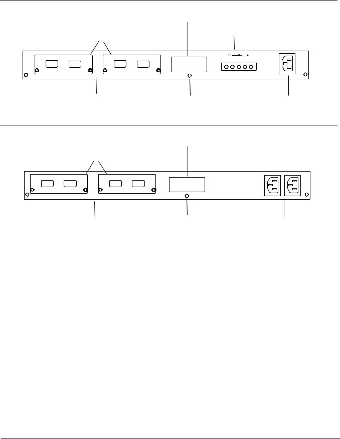
Figure 2 The S25V Rear View
Label (Part #, Serial #, MAC Address, Bar Code, FRU #)
|
|
|
DC Power |
||
10-Gigabit Modules or Stacking Modules (optional) |
|
|
|||
|
|
|
|
|
11.5 |
|
|
|
|
RTN-48V |
Current |
|
|
|
FG |
-48V Sharing |
|
28 |
27 |
26 |
25 |
|
|
|
Ethernet Port Numbers |
Ground Connector |
|
AC Power Receptacle |
|
|
25 to 28, Right to Left |
|
|
|
|
fn00158s25V
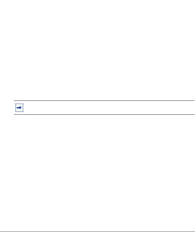
Figure 3 The S25N Rear View
Label (Part #, Serial #, MAC Address, Bar Code, FRU #)
10-Gigabit Modules or Stacking Modules (optional)
fn00158s25P
28 |
27 |
26 |
25 |
|
Ethernet Port Numbers 25 to 28 |
Ground Connector |
Dual AC Power Receptacles |
||
(numbered right to left, facing rear) |
|
|||
Equipment
The following items are necessary to install the system:
•The switch
•At least one grounded AC power source for the S25N switch (ideally two for the two AC receptacles), and one for the S25V. The S25V provides the option of using DC power with, or in addition to, AC.
•Cable (included) to connect the AC power source to the switch
•Brackets (“rack ears”) for rack installation (included)
•Screws for rack installation (included) and #2 Phillips screwdriver (not supplied)
Other optional components are:
•Stacking cables for connecting switches when stacked (not supplied). See Connecting Stack Ports (optional) on page 27.
•Backup DC Power Module (see Chapter 4, Installing Backup Power, on page 31)
•Rear rack-mounting kits (see Installing the System in a Rack or Cabinet on page 21)
•Optical networking components (see Chapter 5, Installing Ports, on page 37)
•Stacking components (see Ports, below)
10 |
System Overview |
Features
•Dual power supplies:
—S25N: Two 150W AC power supplies (two receptacles; see Figure 3 on page 10) acting in load-sharing mode.
—S25V: Internal AC (110v/220v auto-detect) and DC (-48V) power supplies (see Figure 2 on page 10) each capable of 470W, and acting in load-sharing mode. The S25V has built-in support for 360W Power over Ethernet (PoE) — IEEE 802.3af — through the copper ports, with power allocation controll available through the CLI. The optional Force10 470W DC Redundant Power Supply can be attached in current-sharing mode to provide up to 940W (790W of PoE).
•Supports up to 16384 MAC address entries supported with hardware-assisted aging
•Stackable switch features
•19-inch rack-mountable and standard 1U chassis height
•Fans:
—S25N: Four fans with automatic speed adjustment for temperature changes
—S25V: Five fans with automatic speed adjustment for temperature changes
•Supports 9252-byte jumbo frames
•Back-pressure support at half-duplex, IEEE 802.3x flow control at full duplex
•Extensive LED system with per-port LEDs
•32MB internal Flash memory
•256MB RAM
Ports
•24 fixed 10/100/1000 Mbps auto-sensing and auto-MDIX RJ45 ports (The S25V provides up to 15.4W PoE to each port.)
•Four SFP ports that share port numbers 21–24 with the copper ports and capable of using 10/100/1000 Base-T or 1000 Base-X using auto-media detect
•Console port (see Chapter 5, Installing Ports, on page 37): Supplied with console cable (straight-through Ethernet copper cable) and terminal adapter (DB-9 to RJ-45)
•Expansion slots that accept any combination of the following optional, high-capacity uplink modules: 10GbE XFP (two ports), 10GbE CX4 (two ports), 12G stacking (two ports) or 24G stacking (one port). See Inserting Optional Modules (10-Gigabit or Stacking) on page 19 and Connecting Stack Ports (optional) on page 27.
Installing S25N and S25V Systems |
11 |

System Status
Chassis status can be derived in several ways, including physical LED displays and boot menu options, along with CLI show commands and SNMP traps. For details on boot menu and CLI options, see:
•The CLI Basics and BOOT_USER chapters in the FTOS Command Reference for the S-Series
•The Configuration Fundamentals and Getting Started chapters in the FTOS Configuration Guide for the S-Series
LED Displays
As shown in Figure 1 on page 9, the front panel of the switch contains several sets of LEDs:
•The LED group labeled “STACK ID” at the far left of the front panel displays the stack ID of the unit. See Stack ID in Table 3. For more on unit numbering, see Stacking on page 26.
•Each port has status indicator LEDs, described in Table 2.
•A group of status indicator LEDs are on the left side of the front panel, described in Table 3.
Table 2 Port LED Displays
Feature |
Description |
|
|
10/100/1000 Port LED* |
Speed LED (left side of each port) |
|
Green — 1000M |
|
Amber — 100M |
|
Off — 10M |
|
Link/Active LED (right side of each port) |
|
Green — Link up on this port |
|
Blinking Green — Activity, transmitting or receiving packet at this port. |
|
Amber — Link up and power supplied on this port |
|
Blinking Amber – Transmitting or receiving packets on the port and sending PoE |
|
power to PD (power device) |
|
Off — No Link detected at this port |
|
|
SFP Port LED* |
Link LED |
|
Green — Link up on this port |
|
Off — No link detected on this port |
|
Activity LED |
|
Blinking Green — Activity, transmitting or receiving packet in link up state |
|
Off — No activity on this port |
|
|
XFP Port LED |
Link/Activity LED (Each XFP port has a status LED on the module and in the LED group |
|
at the left front of the switch) |
|
Green — Link up on this port |
|
Blinking Green — Activity, transmitting or receiving packet in link up state |
|
Off — No link detected on this port |
* The SFP ports have priority over the four shared 10/100/1000 ports (ports 21–24). LEDs for a 10/100/1000 port are inactive if the shared SFP port (also labeled 21 through 24) is enabled.
12 |
System Overview |

Table 3 describes the LED status indicators on the left side of the front panel.
Table 3 Status Panel LED Display
Label |
LED Color |
Description |
|
|
|
|
|
Left Side of the Status LED Group |
|
|
|
OK |
Green |
Unit is online. |
|
Off |
Unit is powered off. |
|
Green Blinking |
Unit is booting up. (blinking rate is 16 Hz) |
|
Amber |
Error during boot-up. |
|
|
|
AC1 (on S25N) |
Green |
Power supply is present and OK. |
AC (on S25V) |
Amber |
Power supply is present but failed. |
|
Off |
Power supply is not present. |
|
|
|
XFP25* |
Green |
A valid 10G link is established on the port. |
|
Blinking Green |
Transmitting or receiving packets on the port. |
|
Off |
No link is established on the port. |
|
|
|
XFP26* |
Green |
A valid 10G link is established on the port. |
|
Blinking Green |
Transmitting or receiving packets on the port. |
|
Off |
No link is established on the port. |
|
|
|
STACK ID |
Green |
Indicates the stack ID (sometimes called "switch ID") of the unit. |
|
|
Starting with FTOS 7.8.1.0: |
|
|
• “A” is displayed to the left of the stack ID if the unit is a standalone or |
|
|
master (management) unit. |
|
|
• “B” is displayed for a standby unit. (Actually, it’s an 8, because of the |
|
|
limitations of the 7-segment LED.) |
|
|
• “0” is displayed next to the stack ID, as before, for the other units. |
|
|
|
|
|
Right Side of the Status LED Group |
|
|
|
Alarm |
Amber |
Minor alarm: Fan or temperature is operating outside parameters. |
|
Red |
Major alarm |
|
Off |
No alarm |
|
|
|
AC2 (on S25N) |
Green |
Power supply is present and OK. |
DC (on S25V) |
Amber |
Power supply is present but failed. |
|
||
|
Off |
Power supply is not present. |
|
|
|
XFP27* |
Green |
A valid 10G link is established on the port. |
|
Blinking Green |
Transmitting or receiving packets on the port. |
|
Off |
No link is established on the port. |
|
|
|
XFP28* |
Green |
A valid 10G link is established on the port. |
|
Blinking Green |
Transmitting or receiving packets on the port. |
|
Off |
No link is established on the port. |
|
|
|
* Each of the four XFP LEDs on the front panel also indicate the status when CX4 ports are installed in the rear bays.
Installing S25N and S25V Systems |
13 |

14 |
System Overview |
Chapter 2 |
Site Preparation |
|
|
This chapter describes requirements and procedures to install your S25N or S25V system, in the following topics:
•Site Selection
•Cabinet Placement on page 16
•Rack Mounting on page 16
•Fans and Airflow on page 16
•Power on page 17
•Storing Components on page 18
•Tools Required on page 18
For detailed system specifications, refer to Chapter 6, System Specifications, on page 41.
Note: Install the system into a rack or cabinet before installing any optional components.
Site Selection
Make sure that the area where you install the system meets the following safety requirements:
•Near an adequate power source. Connect the system to the appropriate branch circuit protection as defined by your local electrical codes.
•Ambient temperature between 32° – 122°F (0° – 50°C).
•Relative humidity that does not exceed 85% non-condensing.
•In a dry, clean, well-ventilated, and temperature-controlled room, away from heat sources such as hot air vents or direct sunlight.
•Away from sources of severe electromagnetic noise.
•Positioned in a rack, cabinet, or on a desktop with adequate space in the front, rear, and sides of the unit for proper ventilation, and access.
Installing S25N and S25V Systems |
15 |

Cabinet Placement
The cabinet must meet the following criteria:
•Minimum cabinet size and airflow are according to the EIA standard.
•Minimum of 5 inches (12.7 cm) between the side intake and exhaust vents and the cabinet wall.
Rack Mounting
When you prepare your equipment rack, ensure that the rack is earth ground. The equipment rack must be grounded to the same ground point used by the power service in your area. The ground path must be permanent.
Fans and Airflow
Ventilation is side-to-side, with five fans (four fans in the S25N) on the left side of the switch that operate at a constant speed. For proper ventilation, position the system in an equipment rack (or cabinet) with a minimum of five inches (12.7 cm) of clearance around the side intake and exhaust vents. When two S-Series systems are installed side by side, position the two systems at least 5 inches (12.7 cm) apart to permit proper airflow. The acceptable ambient temperature ranges are listed in Environmental Parameters on page 41.
As listed in Table 3, “Status Panel LED Display,” on page 13, the front panel of the system has an Alarm status LED, which is green when the switch is operating within required temperature parameters and all components are operating normally, including fans. The LED is amber when the temperature or components are outside expected parameters, red in a major alarm.
FTOS turns on major and minor alarms and logs temperature warnings at the following temperatures (in degrees Celsius), and logs another message when the temperature returns to normal. The Command Line Interface (CLI) also reports an alarm. The fan speed changes accordingly.
Table 4 Major and Minor Temperature (Degrees Celsius) Warnings
|
S25N |
S25V |
|
|
|
Major On |
62 |
60 |
|
|
|
Major Off |
58 |
56 |
|
|
|
Minor On |
60 |
58 |
|
|
|
Minor Off |
50 |
47 |
|
|
|
Use the show logging command to see the log messages. For details, see the logging chapters of the Command Reference and Configuration Guide. In a stack, each unit has its own temperature monitoring and control. Status logging is identified by unit in the system log.
Fan replacement in the field is not offered as an option.
16 |
Site Preparation |

Power
S25N
The S25N comes standard with two 150W AC power supplies with auto-sensing 110/220V AC receptacles, each of which, when connected to a power source, is capable of supplying all required power to the switch. When both are connected to power sources, they act in load-sharing mode; see Figure 3 on page 10. Use the power cords shipped with the S25N to connect it to AC power outlets, ideally on separate circuits. Several versions of the power cord are available, based on country requirements.
Caution: The power supply cord is used as the main disconnect device; ensure that the socket-outlet is located/installed near the equipment and is easily accessible.
S25V
As shown in Figure 2 on page 10, the right side (as you face the back of the unit) of the S25V contains one auto-sensing 110/220V AC receptacle and a -48V DC terminal block.
When both the AC and DC power supplies are connected on the S25V, it uses them in load-sharing mode. If the 470W DC Backup Power Supply provided by Force10 is connected to the Current Sharing connection on the back of the S25V, the system uses the DC and AC in current-sharing mode, which is load-sharing up to 470W, while also allowing them to provide a total of 940W. The 470W PSU is oversized in order to support PoE, as described next. See also Backup Power Components on page 31.
For details on connecting to a power source, see Supplying Power on page 29.
Power over Ethernet (PoE) Support
Along with the optional DC power supply noted above, the S25V includes an internal 470W power supply that supports both the operation of the switch and an independent power distribution system to supply power to the 24 copper Ethernet ports that support the IEEE 802.3af standard for Power over Ethernet (PoE).
Connect only powered devices that adhere to IEEE 802.3af.
The total PoE power budget for the switch is between 320W and 790W, depending on the power sources available. If the external 470W DC Force10 Redundant Power Supply (catalog # S50-01-PSU-V) is attached to the Current Sharing terminal (see Chapter 4, Installing Backup Power, on page 31), you can use the power-budget command in FTOS to convert its use to current-sharing mode to provide up to 790W of PoE.
Each port can provide a maximum of 15.4W, subject to the power budget, voltage, power priority, and power limit settings. PoE is, by default, enabled globally on a first-come, first-serve basis, until it exceeds the total available power. Alternatively, the switch administrator can use the CLI to allocate power on a per-port and a per-stack-unit basis, with per-port power limits and port prioritization. For a brief introduction in this guide to the PoE commands, see Connecting S25V Ethernet Ports with PoE on
page 38.
Installing S25N and S25V Systems |
17 |
Loading...