


 Loading...
Portable Manual
iR1018/1019/1022/1023 Series
Sep 22 2006
Application
This manual has been issued by Canon Inc. for qualified persons to learn technical theory, installation, maintenance, and repair of products. This manual covers all localities where the products are sold. For this reason, there may be information in this manual that does not apply to your locality.
Corrections
This manual may contain technical inaccuracies or typographical errors due to improvements or changes in products. When changes occur in applicable products or in the contents of this manual, Canon will release technical information as the need arises. In the event of major changes in the contents of this manual over a long or short period, Canon will issue a new edition of this manual.
The following paragraph does not apply to any countries where such provisions are inconsistent with local law.
Trademarks
The product names and company names used in this manual are the registered trademarks of the individual companies.
Copyright
This manual is copyrighted with all rights reserved. Under the copyright laws, this manual may not be copied, reproduced or translated into another language, in whole or in part, without the written consent of Canon Inc.
COPYRIGHT © 2001 CANON INC.
Printed in Japan
Caution
Use of this manual should be strictly supervised to avoid disclosure of confidential information.

Introduction
Symbols Used
This documentation uses the following symbols to indicate special information:
Symbol Description
Indicates an item of a non-specific nature, possibly classified as Note, Caution, or Warning.
Indicates an item requiring care to avoid electric shocks.
Indicates an item requiring care to avoid combustion (fire).
Indicates an item prohibiting disassembly to avoid electric shocks or problems.
Indicates an item requiring disconnection of the power plug from the electric outlet.
Indicates an item intended to provide notes assisting the understanding of the topic in question.
Memo
Indicates an item of reference assisting the understanding of the topic in question.
REF.
Provides a description of a service mode.
Provides a description of the nature of an error indication.

Introduction
The following rules apply throughout this Service Manual:
1.Each chapter contains sections explaining the purpose of specific functions and the relationship between electrical and mechanical systems with reference to the timing of operation.
In the diagrams,  represents the path of mechanical drive; where a signal name accompanies the symbol , the arrow
  indicates the
direction of the electric signal.
The expression "turn on the power" means flipping on the power switch, closing the front door, and closing the delivery unit door, which results in supplying the machine with power.
2.In the digital circuits, '1'is used to indicate that the voltage level of a given signal is "High", while '0' is used to indicate "Low".(The voltage value, however, differs from circuit to circuit.) In addition, the asterisk (*) as in "DRMD*" indicates that the DRMD signal goes on when '0'.
In practically all cases, the internal mechanisms of a microprocessor cannot be checked in the field. Therefore, the operations of the microprocessors used in the machines are not discussed: they are explained in terms of from sensors to the input of the DC controller PCB and from the output of the DC controller PCB to the loads.
The descriptions in this Service Manual are subject to change without notice for product improvement or other purposes, and major changes will be communicated in the form of Service Information bulletins.
All service persons are expected to have a good understanding of the contents of this Service Manual and all relevant Service Information bulletins and be able to identify and isolate faults in the machine."

Contents
Contents
Chapter 1 Maintenance and Inspection |
|
1.1 Periodically Replaced Parts ............................................................................................................................... |
1 |
1.1.1Periodically Replaced Parts ......................................................................................................................... |
1 |
1.2 Durables and Consumables............................................................................................................................... |
1 |
1.2.1Durables .......................................................................................................................................................... |
1 |
1.3 Scheduled Servicing Basic Procedure ............................................................................................................. |
1 |
1.3.1Periodeical Service Items............................................................................................................................. |
1 |
Chapter 2 Standards and Adjustments |
|
2.1 Image Adjustments.............................................................................................................................................. |
3 |
2.1.1Image parallelism adjustment...................................................................................................................... |
3 |
2.2 Scanning System................................................................................................................................................. |
4 |
2.2.1Procedure after Replacing the CS ............................................................................................................. |
4 |
2.2.2Procedure after Replacing the Copyboard Glass (if equipped with SEND functions)........................ |
4 |
2.3 Electrical Components ........................................................................................................................................ |
4 |
2.3.1Procedure after Replacing the Image Processor PCB ............................................................................ |
4 |
2.3.2Actions to Take before All Clearing (Backing up the User Data) ........................................................... |
4 |
Chapter 3 Error Code |
|
3.1 Error Code Details ............................................................................................................................................... |
7 |
3.1.1Error Code Details ......................................................................................................................................... |
7 |
3.2 Jam Code.............................................................................................................................................................. |
8 |
3.2.1Jam Codes (Main body)................................................................................................................................ |
8 |
3.2.2Jam Codes (ADF) .......................................................................................................................................... |
8 |
Chapter 4 User Mode Items |
|
4.1 User Mode Items................................................................................................................................................ |
11 |
4.1.1COMMON SETTINGS ................................................................................................................................ |
11 |
4.1.2COPY SETTINGS........................................................................................................................................ |
11 |
4.1.3TX/RX SETTINGS ....................................................................................................................................... |
12 |
4.1.4ADDRESS BOOK SET. .............................................................................................................................. |
12 |
4.1.5PRINTER SETTINGS ................................................................................................................................. |
14 |
4.1.6TIMER SETTINGS ...................................................................................................................................... |
14 |
4.1.7ADJUST./CLEANING.................................................................................................................................. |
15 |
4.1.8REPORT SETTINGS .................................................................................................................................. |
15 |
4.1.9SYSTEM SETTINGS .................................................................................................................................. |
15 |
Chapter 5 Service Mode |
|
5.1 Fax System Service Mode ............................................................................................................................... |
19 |

Contents |
|
5.1.1 Service Soft Switch Settings (SSSW) ..................................................................................................... |
19 |
5.1.1.1 Outline................................................................................................................................................... |
19 |
5.1.1.2 SSSW-SW01 ....................................................................................................................................... |
19 |
5.1.1.3 SSSW-SW03 ....................................................................................................................................... |
19 |
5.1.1.4 SSSW-SW04 ....................................................................................................................................... |
20 |
5.1.1.5 SSSW-SW05 ....................................................................................................................................... |
20 |
5.1.1.6 SSSW-SW12 ....................................................................................................................................... |
21 |
5.1.1.7 SSSW-SW13 ....................................................................................................................................... |
21 |
5.1.1.8 SSSW-SW14 ....................................................................................................................................... |
22 |
5.1.1.9 SSSW-SW28 ....................................................................................................................................... |
22 |
5.1.1.10 SSSW-SW30 ..................................................................................................................................... |
23 |
5.1.1.11 SSSW-SW34 ..................................................................................................................................... |
23 |
5.1.2 Menu Switch Settings (MENU)................................................................................................................. |
24 |
5.1.2.1 Menu Switch Composition ................................................................................................................. |
24 |
5.1.2.2 <No.005 NL equalizer> ...................................................................................................................... |
24 |
5.1.2.3 <No.006 telephone line monitor> ..................................................................................................... |
24 |
5.1.2.4 <No.007 ATT transmission level> .................................................................................................... |
24 |
5.1.2.5 <No.008 V.34 modulation speed upper limit> ................................................................................ |
24 |
5.1.2.6 <No.009 V.34 data speed upper limit> ............................................................................................ |
24 |
5.1.2.7 <No.010 Frequency of the pseudo CI signal>................................................................................ |
25 |
5.1.3 Numeric Parameter Settings (NUMERIC Param.) ................................................................................ |
25 |
5.1.3.1 Numerical Parameter Composition .................................................................................................. |
25 |
5.1.3.2 <002: RTN transmission condition (1)><003: RTN transmission condition (2)><004: RTN |
|
transmission condition (3)>........................................................................................................................ |
25 |
5.1.3.3 <005: NCC pause length (pre-ID code)> ........................................................................................ |
25 |
5.1.3.4 <006: NCC pause length (post-ID code)>....................................................................................... |
25 |
5.1.3.5 <010: line connection identification length>.................................................................................... |
26 |
5.1.3.6 <011: T.30 T1 timer (for reception)> ................................................................................................ |
26 |
5.1.3.7 <013: T.30 EOL timer>....................................................................................................................... |
26 |
5.1.3.8 <015: hooking detection time>.......................................................................................................... |
26 |
5.1.3.9 <016: time length to first response at time of fax/tel switchover> ............................................... |
26 |
5.1.3.10 <017: pseudo RBT signal pattern ON time length><018: pseudo RBT signal pattern OFF time |
|
length (short)><019: pseudo RBT signal pattern OFF time length (long)> ....................................... |
26 |
5.1.3.11 <020: pseudo CI signal pattern ON time length><021: pseudo CI signal pattern OFF time |
|
length (short)><022: pseudo CI signal pattern OFF time length (long)> ........................................... |
26 |
5.1.3.12 <023: CNG detention level for fax/tel switchover> ...................................................................... |
26 |
5.1.3.13 <024: pseudo RBT transmission level at time of fax/tel switchover> ....................................... |
26 |
5.1.3.14 <025: Answering machine connection function signal detection time>.................................... |
26 |
5.1.3.15 <027: V.21 low-speed flag preamble identification length>........................................................ |
26 |
5.1.3.16 <056 - 061: Count type select >...................................................................................................... |
26 |
5.1.4 Scanner Function Settings (SCANNER)................................................................................................. |
29 |
5.1.4.1 Numeric Parameter Functional configuration ................................................................................. |
29 |
5.1.4.2 <024:CIS scan position during ADF scanning> ............................................................................. |
30 |
5.1.4.3 <026:Distance from the standby position of CIS to the shading start point> ............................ |
30 |
5.1.4.4 <031: Vertical scan start position adjustment> .............................................................................. |
30 |
5.1.4.5 <032: Horizontal scan start position adjustment>.......................................................................... |
30 |
5.1.4.6 <033: Vertical scan magnification correction>................................................................................ |
31 |
5.1.4.7 <034: Horizontal scan magnification correction>........................................................................... |
31 |
5.1.4.8 <035: - 036:Reader motor speed change>..................................................................................... |
31 |

Contents
5.1.4.9<041: Vertical scan start position adjustment (when scanning on a document fed from ADF)>
31
5.1.4.10<042: Horizontal scan start position adjustment (when scanning on a document fed from
ADF)> ............................................................................................................................................................ |
31 |
5.1.4.11 <043: Horizontal scan end position correction ((copy:scanning on ADF)> .............................. |
31 |
5.1.4.12 <044: Horizontal scan end position correction (superfine:scanning on ADF)>........................ |
31 |
5.1.4.13 <045: Horizontal scan end position correction (fine:scanning on ADF)>.................................. |
31 |
5.1.4.14 <046: Horizontal scan end position correction (standard:scanning on ADF)> ........................ |
31 |
5.1.4.15<047: Vertical scan magnification correction (when scanning on a document fed from ADF)>
31
5.1.4.16<048: Horizontal scan magnification correction (when scanning on a document fed from
ADF)> ............................................................................................................................................................ |
31 |
5.1.4.17 <054: Pickup motor speed correction (when the ADF is used) > .............................................. |
31 |
5.1.4.18 <193: ADF special standard-sized paper: LGL misidentification-ready>.................................. |
31 |
5.1.4.19 <194: ADF special standard-sized paper: LTR misidentification-ready>.................................. |
32 |
5.1.4.20 <195: ADF special standard-sized paper: LTR_R misidentification-ready> ............................ |
32 |
5.1.4.21<213: XYZ correction value (X) of standard white plate> (equipped with SEND functions)..32
5.1.4.22<214: XYZ correction value (Y) of standard white plate> (equipped with SEND functions)..32
5.1.4.23<215: XYZ correction value (Z) of standard white plate> (equipped with SEND functions)..32
5.1.5 Printer Function Settings (PRINTER) ...................................................................................................... |
32 |
5.1.5.1 Service Soft Switch Settings .............................................................................................................. |
32 |
5.1.5.2 Numeric Parameter Settings (NUMERIC Param.) ......................................................................... |
34 |
5.1.6 Registration of Accessories (ACC)........................................................................................................... |
36 |
5.1.6.1 Accessory Registration ....................................................................................................................... |
36 |
5.1.7 Display of Counter Information (COUNTER) .......................................................................................... |
36 |
5.1.7.1 Counters................................................................................................................................................ |
36 |
5.1.7.2 Clearing Counters................................................................................................................................ |
36 |
5.1.8 Report Output (REPORT) .......................................................................................................................... |
38 |
5.1.8.1 Report Output....................................................................................................................................... |
38 |
5.1.8.2 System Data List.................................................................................................................................. |
38 |
5.1.8.3 System Dump List................................................................................................................................ |
38 |
5.1.8.4 Counter List .......................................................................................................................................... |
40 |
5.1.8.5 Error Log List ........................................................................................................................................ |
40 |
5.1.8.6 Spec List................................................................................................................................................ |
42 |
5.1.8.7 Service Label........................................................................................................................................ |
43 |
5.1.9 Download (DOWNLOAD) .......................................................................................................................... |
44 |
5.1.9.1 Download .............................................................................................................................................. |
44 |
5.1.10 Data Initialization Mode (CLEAR)........................................................................................................... |
44 |
5.1.10.1 Clear..................................................................................................................................................... |
44 |
5.1.11 Error Display (ERROR DISPLAY) .......................................................................................................... |
44 |
5.1.11.1 Error Display....................................................................................................................................... |
44 |
5.1.12 Display of ROM Information (ROM) ....................................................................................................... |
44 |
5.1.12.1 ROM display ....................................................................................................................................... |
44 |
5.1.13 Test Mode (TEST MODE)........................................................................................................................ |
45 |
5.1.13.1 D-RAM Test<(1) D-RAM TEST>..................................................................................................... |
45 |
5.1.13.2 Scan Test ((2) SCAN TEST)............................................................................................................ |
45 |
5.1.13.3 Print Test ((3) PRINT TEST)............................................................................................................ |
45 |
5.1.13.4 MODEM Test ((4) MODEM TEST) ................................................................................................. |
46 |
5.1.13.5 FUNCTION TEST <(6) FUNCTION TEST> .................................................................................. |
48 |

Contents |
|
5.1.13.6 Roller cleaning mode ((0) ROLLER CLEAN)................................................................................ |
52 |
Chapter 6 Outline of Components |
|
6.1 Clutch/Solenoid ................................................................................................................................................. |
53 |
6.1.1List of Clutches/Solenoids/Motors/Fans .................................................................................................. |
53 |
6.2 Sensor................................................................................................................................................................. |
54 |
6.2.1List of Sensors............................................................................................................................................. |
54 |
6.3 Lamps, Heaters, and Others ........................................................................................................................... |
55 |
6.3.1List of Lamps, Heaters, and Others ......................................................................................................... |
55 |
6.4 PCBs ................................................................................................................................................................... |
57 |
6.4.1List of PCBs ................................................................................................................................................. |
57 |
Chapter 7 System Construction |
|
7.1 Construction....................................................................................................................................................... |
59 |
7.1.1Functional Construction ............................................................................................................................. |
59 |
7.1.2Functional Block Diagram.......................................................................................................................... |
60 |
7.1.3Image Processor PCB................................................................................................................................ |
60 |
7.1.4DC Controller PCB...................................................................................................................................... |
61 |
7.1.5Analog Processor PCB .............................................................................................................................. |
62 |
7.1.6Power Supply PCB ..................................................................................................................................... |
62 |
7.1.7Relay PCB.................................................................................................................................................... |
62 |
7.1.8Control Panel PCB...................................................................................................................................... |
62 |
7.1.9NCU PCB (if equipped with fax functions) .............................................................................................. |
62 |
7.1.10Network PCB (if equipped with network functions).............................................................................. |
62 |
7.1.11Modular Jack PCB (if equipped with fax functions) ............................................................................. |
62 |
7.1.12Modem PCB (if equipped with fax functions)........................................................................................ |
62 |
7.2 System Construction ........................................................................................................................................ |
64 |
7.2.1System Configuration ................................................................................................................................. |
64 |
7.3 Product Specifications...................................................................................................................................... |
67 |
7.3.1Product Specifications................................................................................................................................ |
67 |
7.3.2ADF Specifications...................................................................................................................................... |
68 |
7.3.3Fax Specifications....................................................................................................................................... |
68 |
7.4 Function List....................................................................................................................................................... |
69 |
7.4.1Print Speed (iR1018/iR1018J/1019/iR1019J)) ....................................................................................... |
69 |
7.4.2Print Speed (iR1022/1022A/1022F/1022i/1022iF/1022J/1022N/iR1023/1023N/1023iF)................ |
70 |
7.4.3Types of Paper ............................................................................................................................................ |
70 |
Chapter 8 Upgrading |
|
8.1 Upgrading........................................................................................................................................................... |
73 |
8.1.1Overview of Upgrade.................................................................................................................................. |
73 |
8.1.2Overview of Service Support Tool............................................................................................................ |
73 |
Chapter 1
Chapter 1 Maintenance and Inspection
1.1 Periodically Replaced Parts
1.1.1 Periodically Replaced Parts
/ / / / iR1018 / iR1018J / / iR1022A / iR1022F / iR1022i / iR1022iF / The machine does not have parts that require periodical replacement.
1.2 Durables and Consumables
1.2.1 Durables
/ / / / iR1018 / iR1018J / / iR1022A / iR1022F / iR1022i / iR1022iF / The machine does not have durables.
1.3 Scheduled Servicing Basic Procedure
1.3.1 Periodeical Service Items
/ / / / iR1018 / iR1018J / / iR1022A / iR1022F / iR1022i / iR1022iF / The machine does not have periodecal service items.
1

Chapter 2
Chapter 2 Standards and
Adjustments
2.1 Image Adjustments
2.1.1 Image parallelism adjustment
/ / / / iR1018 / iR1018J / / iR1022A / iR1022F / iR1022i / iR1022iF /
1) Create a test chart, load it in the ADF, and make a copy of it.
Test Sheet |
|
10mm |
10mm |
(feeding direction) |
10mm |
|
|
10mm |
|
F-2-1
2)Compare the lines at the end of the test chart with those on the copy for parallelism. Measure dimensions A and B at the end of the copy and adjust the amount of skew (the range shown in the table) to within the
spec.
Standard: A-B within ±1.7 mm
Test Sheet
 A
A  Rear side
(feeding direction)
B  Front side
F-2-2
<Adjustment method>
This machine allows parallelism between the leading and trailing edges of the image to be adjusted by changing the positions where the front and rear springs of the registration unit are hooked.
There are five types of spring hooking positions. (One step = Approx. 0.6 mm)
|
T-2-1 |
|
Settings |
Spring positions at |
Spring positions at |
|
the back of host |
the front of host |
|
machine |
machine |
|
|
|
1 |
+1 |
-1 |
2 |
+1 |
0 |
3 |
0 |
0 |
4 |
-1 |
0 |
5 |
-1 |
1 |
MEMO:
Parallelism varies depending on the difference in the spring pressure between the front and rear springs.
For example, the spring position "0"at the back of the host machine and the spring position "-1"at the front of the host machine are not shown in this document because they are the same as the spring position "+1"at the back of the host machine and the spring position "0t the front of the host machine respectively.
-1
Rear
-1
0
+1
Front
F-2-3
1)Check the current hooking positions of the left and right springs of the registration roller. Change the spring hooking positions in reference to the table below. (They are adjustable in five steps. One step = Approx. 0.6 mm)
|
T-2-2 |
|
|
|
Settings |
Spring |
Spring positions |
|
|
positions at |
at the front of |
|
|
the back of |
host machine |
|
|
host machine |
|
|
|
|
|
Correction of image A |
1 |
+1 |
-1 |
(The A-side extends.) |
|
|
|
|
2 |
+1 |
0 |
|
3 |
0 |
0 |
|
4 |
-1 |
0 |
Correction of image B |
5 |
-1 |
1 |
(The B-side extends.) |
|
|
|
-If the A-side image (at the front of the host machine) is short (shrunken), reduce the setting value.
 A
A
(feeding direction)
B
F-2-4
-If the B-side image (at the back of the host machine) is short (shrunken), increase the setting value.
A
(feeding direction)
B
F-2-5
3
Chapter 2
2.2 Scanning System
2.2.1 Procedure after Replacing the CS
/ / / / iR1018 / iR1018J / / iR1022A / iR1022F / iR1022i / iR1022iF /
After replacing the contact sensor (CS), go through the following steps to perform inter-channel output correction:
1) Enter the service mode.
Sequentially press the Additional functions key, 2 key, 8 key, and Additional functions key on the operation panel.
2)Press the arrow key on the touch panel to display "TEST MODE".
3)Press [OK].
4)Press the [2] key to display "SCAN TEST".
5)Press the [1] key to display "SHADING".
6)Press [OK].
After completion of the above procedure, the contact sensor output is compensated and parameters are set automatically.
After completion of automatic adjustment, "OK" is displayed.
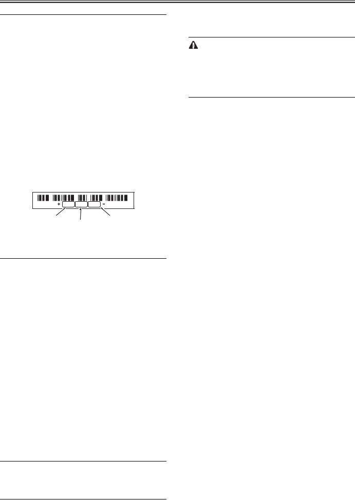
2.2.2 Procedure after Replacing the Copyboard Glass (if equipped with SEND functions)
/ / / / iR1018 / iR1018J / / iR1022A / iR1022F / iR1022i / iR1022iF /
After replacing the copyboard glass, enter the correction values (X, Y, Z) of the standard white plate which are indicated on the back of the new copyboard glass in the service mode.
Correction value (X): Service mode>#SCAN>#SCAN NUMERIC>No.213 Correction value (Y): Service mode>#SCAN>#SCAN NUMERIC>No.214 Correction value (Z): Service mode>#SCAN>#SCAN NUMERIC>No.215 Also, rewrite the values on the service label.
820686679349 |
correcton |
correcton |
value (X) |
correcton value (Z) |
|
value (Y) |
F-2-6
2.3 Electrical Components
2.3.1 Procedure after Replacing the Image Processor PCB
/ / / / iR1018 / iR1018J / / iR1022A / iR1022F / iR1022i / iR1022iF /
If you have replaced the image processor PCB with a new one, perform the following operations:
-Using the service support tool, download the latest firmware (System/Boot/ PCL*1) and language files.
*1: if equiped with PCL functions.
-Input the all value printed on the service label affixed to the rear cover. Make the following adjustments:
-Correction of output between CIS channels
1) Enter the service mode.
Sequentially press the Additional functions key, 2 key, 8 key, and Additional functions key on the operation panel.
2)Press the arrow key on the touch panel to display "TEST MODE".
3)Press [OK].
4)Press the [2] key to display "SCAN TEST".
5)Press the [1] key to display "SHADING".
6)Press [OK].
After completion of the above procedure, the contact sensor output is compensated and parameters are set automatically.
After completion of automatic adjustment, "OK" is displayed.
- Read position adjustment (Stream reading: Only when the ADF is installed) 1) Enter the service mode.
Sequentially press the Additional functions key, 2 key, 8 key, and Additional functions key on the operation panel.
2)Press the arrow key on the touch panel to display "TEST MODE".
3)Press [OK].
4)Press the [2] key to display "SCAN TEST".
5)Press the [3] key to display "SHEET POS ADJ".
6)Press [OK].
The optical system starts scanning. Several seconds later, automatic adjustment of the reading position finishes and "OK" appears.
 If automatic adjustment fails, "NG" appears. Perform the following procedure:
Clean the platen guide of the DADF and the document glass of the host machine, and then retry auto adjustment.
2.3.2 Actions to Take before All Clearing (Backing up the User Data)
/ / / / iR1018 / iR1018J / / iR1022A / iR1022F / iR1022i / iR1022iF /
-Performing the all-clear operation in the service mode (#CLEAR > ALL) erases/initializes the user data such as address data and user mode settings.
Be sure to back up the user data with the data export function before starting the all-clear operation, and then load the user data with tbe data import function.
-To export and import user data, a PC and a USB cable are required. Have them on hand.
a. Exporting user data
1) Output a user data list in the following user mode.
Additional functions key > Report Setting > Plint List > User Data List 2) Press the following keys to enter the service mode.
Additional functions key > 2 key > 8 key > Additional functions key
3)Select "#SYSTEM" using the arrow key, and then press the OK.
4)Select "#SYSTEM SW" using the arrow key, and then press the OK.
5)Press the following keys to display "SW003."
# > 0 key > 3 key
Message: #SYSTEM SW003 00001000
6)Position the cursor at Bit-6 (second from left) using the arrow key, and then press the 1 key.
Message: #SYSTEM SW003 01001000
7)Press the OK key. Check that "SW003" changes to "SW004".
Message: #SYSTEM SW004 00000000
8)Press the Reset key to exit the service mode.
9)Turn off the main power switch, and then turn it on again.
10)Start the PC and connect it to this machine with a USB cable.
11)Open My Computer on the PC to check that the "Removable Disk" icon is displayed. If the "Removable Disk" icon is not displayed, repeat the above procedure starting with step 1.
12)Double-click the "Removable Disk" icon, and then copy the user data (address_book.abk and user_data.dat) onto the Desktop.
13)Close the window on the Desktop.
14)Turn off the main power switch of this machine.
15)Disconnect the USB cable from this machine.
b. Importing user data
1) Press the flowing keys to enter the service mode.
Additional functions key > 2 key > 8 key > Additional functions key 2) Select "#SYSTEM" using the arrow key, and then press the OK.
4)Select "#SYSTEM SW" using the arrow key, and then press the OK.
5)Press the following keys to display "SW003".
# > 0 key > 3 key
Message: #SYSTEM SW003 00001000
5)Check that Bit-6 (second from left) is set to set to "1". If Bit-6 is not set to "1", position the cursor at this bit using the arrow key and then press the 1 key.
Message: #SYSTEM SW003 01001000
6)Press the OK key. Check that "SW003" changes to "SW004".
Message: #SYSTEM SW004 00000000
7)Press the Reset key to exit the service mode.
8)Turn off the main power switch, and then turn it on again.
9)Open My Computer on the PC to check that the "Removal Disk" icon is displayed.
11)Write the user data (address_book.abk and user_data.dat) copied onto the Desktop as described in "a. Exporting user data" over the removable disk.
12)Disconnect the USB cable from the machine.
13)Turn off the main power switch of the machine.
14)Perform steps 1) to 4) again to reset Bit-6 of "SW003" to "0".
15)Press the OK key. When "SW003" changes to "SW004", press the Reset key to exit the service mode.
16)Check the user data list output as described in "a. Exporting user data" to make sure that the user data has been loaded into the machine properly.
4

Chapter 2
5

Chapter 3
Chapter 3 Error Code
3.1 Error Code Details
3.1.1 Error Code Details
/ / / / iR1018 / iR1018J / / iR1022A / iR1022F / iR1022i / iR1022iF /
|
|
|
T-3-1 |
Display |
Detail Code |
Main Cause/Symptom |
Countermeasure |
Code |
|
|
|
E000 |
0000 |
Startup error |
|
|
The temperature detected by the main or sub thermistor does |
|
|
not rise to the specified value during startup control. |
E001 |
0000 |
Abnormally high temperature (detected by main thermistor) |
|
|
The main thermistor detected an abnormally high temperature |
|
|
(235 deg C) during temperature control. |
|
0001 |
Abnormally high temperature (detected by sub thermistor) |
|
|
The sub thermistor detected an abnormally high temperature |
|
|
(300 deg C) during temperature control. |
-Check the fixing film connector.
-Replace the fixing film unit.
-Replace the DC controller PCB.
-Check the connector of the fixing film unit.
-Replace the fixing film unit.
-Replace the DC controller PCB.
-Check the connector of the fixing film unit.
-Replace the fixing film unit.
-Replace the DC controller PCB.
E002 |
0000 |
Low temperature during temperature control. |
|
|
The target temperature is not reached during temperature |
|
|
control. |
E003 |
0000 |
Abnormally low temperature (detected by main thermistor) |
|
|
After the temperature detected by the main thermistor has |
|
|
reached the specified value, it does not reach the specified |
|
|
value during initial rotation. |
|
0001 |
Abnormally low temperature (detected by sub thermistor) |
|
|
After the temperature detected by the sub thermistor has |
|
|
reached the specified value, it does not reach the specified |
|
|
value during initial rotation. |
E010 |
0000 |
Main motor failure |
|
|
The main motor is faulty. |
E019 |
0000 |
Waste toner full detection |
|
|
The waste toner full state was detected. |
|
0001 |
Waster toner full detection sensor is faulty. |
|
|
The waste toner full state was detected continuously for five or |
|
|
more seconds while the main motor was turning. |
E100 |
0000 |
BD detection PCB failure |
|
|
The BD detection PCB is faulty. |
E196 |
0001 |
Flash ROM write/read error |
|
|
The write/read of Flash ROM in the image processor PCB is |
|
|
faulty. |
|
0002 |
PCL ROM write/read error |
|
|
The write/read of PCL ROM in the image processor PCB is |
|
|
faulty. |
E197 |
0000 |
Printer engine communication error |
|
|
Erroneous communication between the DC controller PCB and |
|
|
image processor PCB was detected. |
E716 |
0000 |
Erroneous communication with optional cassette |
|
|
Disconnection of the optional cassette was detected after |
|
|
power-on, detection of normal connection to the optional |
|
|
cassette, and start of communication. |
-Check the connector of the fixing film unit.
-Replace the fixing film unit.
-Replace the DC controller PCB.
-Check the connector of the fixing film unit.
-Replace the fixing film unit.
-Replace the DC controller PCB.
-Check the connector of the fixing film unit.
-Replace the fixing film unit.
-Replace the DC controller PCB.
-Check the connector of the main motor.
-Replace the main motor.
-Replace the DC controller PCB.
Replace the drum unit
-Check the connector of the waster toner full sensor.
-Replace the waste toner full sensor.
-Replace the DC controller PCB.
-Check the connector of the BD detection PCB.
-Replace the laser scanner unit.
-Replace the DC controller PCB.
-Replace the image processor PCB.
-Replace the PCL PCB.
-Replace the image processor PCB.
-Check the connectors of the DC controller PCB and image processor PCB.
-Replace the DC controller PCB for normal connection.
-Replace the image processor PCB.
-Check the connectors of the optional cassette PCB and DC controller PCB.
-Replace the optional cassette PCB for normal connection.
-Replace the DC controller PCB.
7

Chapter 3
Display |
Detail Code |
Main Cause/Symptom |
Countermeasure |
Code |
|
|
|
|
|
|
|
E719 |
0000 |
Erroneous communication with card reader (serial communication) |
|
-Disconnection from the card reader has been detected since communication started after confirmation of normal connection to the card reader (after power-on).
-A serial communication error has occurred. (The serial communication error cannot be recovered.)
-Check the connectors of the card reader and image processor PCB.
-Replace the card reader for normal connection.
-Replace the image processor PCB.
|
0001 |
Erroneous communication with coin vendor (serial communication) |
|
|
|
- Disconnection from the coin vendor has been detected since |
- Check the connection between the image processor PCB and |
|
|
communication started after confirmation of normal |
serial PCB. |
|
|
connection to the coin vendor (after power-on). |
- Check the connectors of the serial PCB and coin vendor for |
|
|
- A serial communication error has occurred. (The serial |
normal connection. |
|
|
communication error cannot be recovered.) |
- Replace the serial PCB. |
|
|
|
- Check the coin vendor. |
|
|
|
- Replace the image processor PCB. |
E730 |
0000 |
inside error of the image processor PCB (PDL system error) |
- Replace the image processor PCB. |
|
|
The inside of the image processor PCB is faulty. |
|
E733 |
0000 |
Erroneous communication between controller and printer |
|
Cannot communicate with the printer at startup.
-Check the connectors of the DC controller PCB and image processor PCB for normal connection.
-Check the power supply of the printer (Check whether initialization is performed at startup).
-Replace the DC controller PCB or image processor PCB.
E736 |
0000 |
CCU communication error |
|
|
|
The installed modem PCB is incompatible. |
- Check the connectors of the image processor PCB and modem. |
|
|
|
- Replace the modem PCB. |
|
|
|
- Replace the image processor PCB. |
E739 |
0000 |
Erroneous communication between controller and network board |
|
The installed network board is incompatible.
-Check the connectors of the image processor PCB and LAN PCB for normal connection.
-Replace the LAN PCB.
-Replace the image processor PCB.
E805 |
0000 |
Fan failure |
|
|
|
The fan is faulty. |
- Check the fan connector. |
|
|
|
- Replace the fan. |
|
|
|
- Replace the DC controller PCB. |
E808 |
0000 |
Fixing drive circuit failure |
|
-The heater does not turn on.
-A fixing drive motor failure was detected.
-Check the connector of the fixing film unit.
-Replace the fixing film unit.
-Replace the fixing drive motor.
-Replace the DC controller PCB.
-Replace the power supply PCB.
3.2 Jam Code
3.2.1 Jam Codes (Main body)
/ / / / iR1018 / iR1018J / / iR1022A / iR1022F / iR1022i / iR1022iF /
|
|
|
T-3-2 |
|
|
|
|
Code |
Name |
Sensor No. |
Description |
|
|
|
|
0104 |
Pickup Delay Jam |
SR11 |
After execution of a pickup retry, the registration sensor (SR11) does not detect the leading edge of |
|
|
|
paper within a specific period of time. Or after the duplex drive solenoid (SL1) is on, the registration |
|
|
|
sensor (SR11) does not detect the leading edge of paper within a specific period of time. |
|
|
|
|
0208 |
Pickup Stationary Jam |
SR11 |
After the registration sensor (SR11) has detected the leading edge of paper, the registration sensor |
|
|
|
(SR11) does not detect the trailing edge of paper within a specific period of time. |
|
|
|
|
010c |
Delivery Sensor Delay Jam |
SR5 |
After the registration sensor (SR11) has detected the leading edge of paper, the delivery sensor |
|
|
|
(SR5) does not detect the leading edge of paper within a specific period of time. |
|
|
|
|
0210 |
Delivery Sensor Stationary |
SR5 |
- The delivery sensor cannot detect absence of paper within the specified time after turning off of |
|
Jam |
|
the registration clutch. |
|
|
|
- The delivery sensor cannot detect absence of paper within the specified time after the sensor |
|
|
|
detected the leading edge of paper. |
|
|
|
|
0214 |
Stationary jam in machine |
SR5, SR9 |
After the registration sensor (SR11) has detected the trailing edge of paper, the delivery sensor |
|
|
|
(SR5) does not detect the trailing edge of paper within a specific period of time. |
|
|
|
|
021c |
Wound Paper Jam at Fuser |
SR5, SR11 |
The delivery sensor (SR5) has detected absence of paper within the prescribed time after it detected |
|
|
|
presence of paper. |
|
|
|
|
1118 |
Door open jam |
SR5, SR9, SR11, |
The door was opened when there was printing paper in the transport path. |
|
|
SW2 |
|
3.2.2 Jam Codes (ADF)
/ / / / iR1018 / iR1018J / / iR1022A / iR1022F / iR1022i / iR1022iF /
|
|
|
T-3-3 |
|
|
|
|
|
|
Code |
Name |
Sensor No. |
|
Description |
0000 |
Unknown jam |
- |
|
Other errors |
|
|
|
|
|
0007 |
Initial stationary |
SR2002, SR2003, SR2004 |
|
Paper is detected in the transport path before the ADF starts initial |
|
|
|
|
operation. |
|
|
|
|
|
8
|
|
|
|
Chapter 3 |
|
|
|
|
|
|
|
|
|
|
|
|
|
|
|
|
|
|
|
|
Code |
Name |
Sensor No. |
Description |
|
|
|
|
|
|
|
|
0008 |
Document edge sensor |
SR2002 |
The document edge sensor does not detect paper when the paper has been fed by the |
|
|
|
delay jam |
|
predetermined distance since reception of a pickup request. |
|
|
|
|
|
|
|
|
0009 |
Document edge sensor |
SR2002 |
The trailing edge of paper is not detected when the paper has been fed by the |
|
|
|
stationary jam |
|
predetermined distance since detection of it by the document edge sensor. |
|
|
|
|
|
|
|
|
000a |
Paper absence (Pull out |
SR2001 |
The Document set sensor has been held off since start of pickup. |
|
|
|
the document.) |
|
|
|
|
|
|
|
|
|
|
000c |
Delivery delay jam |
SR2002 |
In case the internal software signal "Delivery Sensor OFF" set in the system cannot |
|
|
|
|
|
be detected, when the leading edge of paper is detected by the document edge sensor |
|
|
|
|
|
and fed the prescribed distance, and after the paper's trailing edge is detected. |
|
|
|
|
|
|
|
|
000d |
Delivery stationary jam |
SR2002 |
In case the internal software signal "Delivery Sensor ON" set in the system cannot |
|
|
|
|
|
be detected, when the paper feed request is received and the paper is fed the |
|
|
|
|
|
prescribed distance, and the leading edge of paper is detected and paper is fed the |
|
|
|
|
|
prescribed distance . |
|
|
|
|
|
|
|
|
0010 |
Pickup NG |
SR2003 |
The registration sensor has been held off since paper pickup started. |
|
|
|
|
|
|
|
9
Chapter 4
Chapter 4 User Mode Items
4.1 User Mode Items
4.1.1 COMMON SETTINGS
/ / / / iR1018 / iR1018J / / iR1022A / iR1022F / iR1022i / iR1022iF /
MEMO:
User modes of the USA model (Copy + Print + Scan + Fax + ADF + Network + PCL) are described. Menus and defaults may vary depending on the destination. For details, refer to the User's Guide.
Additional Functions |
Available Settings |
1. DEFAULT SETTINGS |
COPY, FAX(*), SCAN |
2. AUTO CLEAR SET. |
INITIAL FUNCTION(*), SELECTED FUNCTION |
3. AUDIBLE TONES |
ENTRY TONE: ON (volume 1(*) to 3), OFF |
|
ERROR TONE: ON (volume 1(*) to 3), OFF |
|
TX JOB DONE TONE: ERROR ONLY (volume 1(*) to 3), OFF, ON (volume 1(*) |
|
to 3) |
|
RX JOB DONE TONE: ERROR ONLY (volume 1(*) to 3), OFF, ON (volume |
|
1(*) to 3) |
|
SCAN DONE TONE: ERROR ONLY (volume 1(*) to 3), OFF, ON (volume 1(*) |
|
to 3) |
|
PRINT DONE TONE: ERROR ONLY (volume 1(*) to 3), OFF, ON (volume 1(*) |
|
to 3) |
4. TONER SAVER MODE |
OFF(*), ON |
5. PRINTER DENSITY |
1 to 9 (5(*)) |
6. AUTO DRAWER SELCT |
COPY: DRAWER 1 (ON(*), OFF), DRAWER 2 (ON(*), OFF), STACK BYPASS |
|
(OFF(*), ON) |
|
PRINTER: DRAWER 1 (ON(*), OFF), DRAWER 2 (ON(*), OFF) |
|
RECEIVE: DRAWER 1 (ON(*), OFF), DRAWER 2 (ON(*), OFF), STACK |
|
BYPASS (OFF(*), ON) |
|
OTHER: DRAWER 1 (ON(*), OFF), DRAWER 2 (ON(*), OFF), STACK |
|
BYPASS (OFF(*), ON) |
7. SELECT PAPER TYPE |
DRAWER 1, DRAWER 2 |
8. REG. PAPER TYPE |
DRAWER 1: PLAIN PAPER(*), COLOR, RECYCLED, HEAVY PAPER 1, |
|
BOND, 3HOLE PUNCH PAPER |
|
DRAWER 2: PLAIN PAPER(*), COLOR, RECYCLED, HEAVY PAPER 1, |
|
BOND, 3HOLE PUNCH PAPER |
9. ENERGY IN SLEEP |
LOW(*), HIGH |
10. BYPASS STD SET |
OFF(*), ON: PAPER SIZE (LTR, SMTR, EXECUTIV, OFICIO, BRAZIL- |
|
OFICIO, MEXICO-OFICIO, FOLIO, G-LTR, FLSP, COM10, MONARCH, DL, |
|
ISO-C5, ISO-B5, FREESIZE, A4, B5, A5R, LGL), SELECT PAPER TYPE |
|
(PLAIN PAPER, COLOR, RECYCLED, HEAVY PAPER 1, HEAVY PAPER 2, |
|
HEAVY PAPER 3, BOND, 3HOLE PUNCH PAPER, TRANSPARENCY, |
|
LABELS, ENVELOPE) |
11. PAPER FEED SWITCH |
STACK BYPASS (SPEED PRIORITY(*), PRINT SIDE), DRAWER 1 (SPEED |
|
PRIORITY(*), PRINT SIDE), DRAWER 2 (SPEED PRIORITY(*), PRINT |
|
SIDE) |
12. DISPLAY LANGUAGE |
ENGLISH(*), FRENCH, SPANISH, PORTUGUESE |
13. ADF DIRTY ERROR |
DISPLAY(*), DO NOT DISPLAY |
14. INIT. COMMON SET. |
OFF(*), ON |
*: indicates factory settings.
4.1.2 COPY SETTINGS
/ / / / iR1018 / iR1018J / / iR1022A / iR1022F / iR1022i / iR1022iF /
Additional Functions |
Available Settings |
|
|
1. IMAGE DIR PRIORTY |
OFF(*), ON |
11

Chapter 4
Additional Functions |
Available Settings |
2. STANDARD SETTINGS |
IMAGE QUALITY: TEXT/PHOTO, TEXT(*), PHOTO |
|
DENSITY: AUTO(*), MANUAL (-LT - DK+: 9 steps, 5) |
|
ZOOM RATIO: PRESET RATIO (DIRECT 100%(*), 115% B5->A4, 121% LGL- |
|
>11x17, 122% A5->B5,129% STMT->LTR,141% A5->A4, 200% MAX., 50% |
|
MIN., 64%, 70% A4->A5, 73% 11X17->LGL, 78% LGL->LTR, 81% B5->A5, |
|
86% A4->B5), MANUAL |
|
COPIES: 1(*) to 99 |
|
AUTO COLLATE: OFF(*), COLLATE |
|
TWO-SIDED: OFF(*), 1 > 2-SIDED, 2 > 2-SIDED, 2 > 1-SIDED |
|
FRAME ERASE: OFF(*), ORG. FRAME ERASE, BOOK FRAME ERASE, |
|
BINDING HOLE |
|
PAPER SELECT: AUTO(*), DRAWER 1, DRAWER 2 |
3. SHARPNESS |
1 to 9 (5(*)) |
4. PAPER SIZE GROUP |
A, AB, INCHES(*) |
5. MM/INCH ENTRY |
mm, INCHES(*) |
6. INIT. COPY SET. |
OFF(*), ON |
*: indicates factory settings.
4.1.3 TX/RX SETTINGS
/ / / / iR1018 / iR1018J / / iR1022A / iR1022F / iR1022i / iR1022iF /
Additional Functions |
Available Settings |
1.COMMON 1.TX SETTINGS SETTING
2.RX SETTINGS
3.CONT.PRIN TING
2.FAX 1.USER SETTING SETTINGS
2.TX SETTINGS
3.RX SETTINGS
UNIT NAME
DATA COMPRESSION: NORMAL(*), HIGH RATIO, LOW LATIO RETRY TIMES (0-5(3*))
SCANNIING DENSITY (1-9(5*))
STANDARD SETTINGS: DENSITY (STANDARD(*), DK, LT), IMAGE QUALITY (200X200DPI(*), 200X400DPI, 300X300DPI, 400X400DPI, 600X600DPI, 100X100DPI, 150X150DPI, 200X100DPI), IMAGE FORMAT (PDF(*), TIFF(B&W), PDF(COMPACT), JPEG), ORIGINAL TYPE ( TEXT/PHOTO(*), TEXT, PHOTO), DIVIDE INTO PAGES (OFF(*), ON), DIRECT TX (OFF(*), ON)
SEND SETTINGS: TX FILE NAME (max.24 characters), SUBJECT (max.40 characters), MESSAGE TEXT (max.140 characters) , REPLY TO (max.120 characters), E-MAIL PRIORITY (NORMAL(*), LOW, HIGH)
TX TERMINAL ID: PRINTING POSITION (OUTSIDE IMAGE(*), INSIDE IMAGE), TELEPHONE # MARK (FAX(*), TEL)
COLOR TX GAMMA: :GAMMA 1.8(*), GAMMA2.2, GAMMA1.0, GAMMA1.4 SHARPNESS (1-7(4*))
COLOR TX SCAN SET: SPEED PRIORITY(*), IMAGE PRIORITY INIT STADARD SET: OFF, ON
TWO-SIDED PRINT: OFF, ON, RECEIVE REDUCTION: ON (RX REDUCTION: AUTO, FIXED REDUCTION(90%, 95%, 97%, 75%), REDUCE DIRECTION: VERTICAL ONLY, HORIZ & VERTICAL), OFF
RX TO MEMORY(*), KEEP PRINTING
UNIT TELEPHONE #
TEL LINE TYPE: TOUCH TONE(*), ROTARY PULSE OFFHOOK ALARM: ON(*), OFF
VOLUME CONTROL: MONITOR VOL. CTRL (0 - 3 (1(*))), CALLING VOLUME (0 - 3 (1(*))) ECM TX: ON(*), OFF
PAUSE TIME: 1 to 15 (2(*)) SEC.
AUTO REDIAL: ON (REDIAL TIMES, REDIAL INTERVAL, TX ERROR REDIAL)(*), OFF TIME OUT: ON, OFF(*)
DIALING LINE CHCK: ON, OFF(*) ECM RX: ON(*), OFF
RX MODE: FAXONLY(*), FAXTEL, ANSMODE, DRPD, Manual
FAX/TEL OPT. SET: RING START TIME (0-30 (6*)), F/T RING TIME: (15-300 (15*)), F/T SWITCH ACTION: RECEIVE(*), DISCONNECT
DRPD:SELECT FAX: DOUBLE RING(*), SHORT-SHORT-LONG, OTHER RING TYPR, NORMAL RING INCOMING RING: OFF(*), ON (RING COUNT (1-99TIMES)
REMOTE RX: ON(*) (REMOTE RX ID (0-99(25*))), OFF
MANUAL/AUTO: OFF(*), ON (F/T RING TIME (1-99SEC)
*: indicates factory settings.
4.1.4 ADDRESS BOOK SET.
/ / / / iR1018 / iR1018J / / iR1022A / iR1022F / iR1022i / iR1022iF /
12

Chapter 4
|
|
|
T-4-1 |
Additional Functions |
|
Available Settings |
|
|
|
|
|
1.FAVORITES |
FAX |
NAME |
max. 16 characters |
BUTTONS |
|
TEL NUMBER ENTRY |
max. 120 digits |
|
|
||
|
|
IMAGEQUALITY |
FINE, PHOTO, SUPER FINE, ULTRA FINE, STANDARD |
|
|
OPTIONAL SETTING |
OFF(*), ON (ECM (ON(*), OFF), TX SPEED (33600bps(*), 14400bps, 9600bps, |
|
|
|
4800bps), INTERNATIONAL (DOMESTIC(*), LONG DISTANCE 1, LONG |
|
|
|
DISTANCE 2, LONG DISTANCE 3) |
|
NAME |
max. 16 characters |
|
|
|
E-MAIL ADDRESS |
max. 120 digits |
|
|
IMAGE FORMAT |
PDF(*), TIFF (B&W), PDF (COMPACT), JPEG |
|
|
DIVIDE INTO PAGES |
OFF(*), ON |
|
|
IMAGEQUALITY |
200x200dpi(*), 200x400dpi, 300x 300dpi, 400x400 dpi, 600x600 dpi, 100x100 dpi, |
|
|
|
150x150 dpi, 200x100dpi |
|
|
ORIGINAL TYPE |
TEXT/PHOTO(*), TEXT, PHOTO |
|
IFAX |
NAME |
max. 16 characters |
|
|
I-FAX ADDRESS |
max. 120 digits |
|
|
DIVIDE INTO PAGES |
OFF(*), ON |
|
|
IMAGEQUALITY |
200x200dpi(*), 200x400dpi, 300x 300dpi, 400x400 dpi, 600x600 dpi, 100x100 dpi, |
|
|
|
150x150 dpi, 200x100dpi |
|
|
ORIGINAL TYPE |
TEXT/PHOTO(*), TEXT, PHOTO |
|
FTP |
NAME |
max. 16 characters |
|
|
HOST NAME |
max. 120 digits |
|
|
FILE PATH |
max. 120 digits |
|
|
LOGIN NAME |
max. 24 characters |
|
|
PASSWORD |
max. 24 characters |
|
|
IMAGE FORMAT |
PDF(*), TIFF (B&W), PDF (COMPACT), JPEG |
|
|
DIVIDE INTO PAGES |
OFF(*), ON |
|
|
IMAGEQUALITY |
200x200dpi(*), 200x400dpi, 300x 300dpi, 400x400 dpi, 600x600 dpi, 100x100 dpi, |
|
|
|
150x150 dpi, 200x100dpi |
|
|
ORIGINAL TYPE |
TEXT/PHOTO(*), TEXT, PHOTO |
|
SMB |
NAME |
max. 16 characters |
|
|
HOST NAME |
max. 120 digits |
|
|
FILE PATH |
max. 120 digits |
|
|
LOGIN NAME |
max. 24 characters |
|
|
PASSWORD |
max. 24 characters |
|
|
IMAGE FORMAT |
PDF(*), TIFF (B&W), PDF (COMPACT), JPEG |
|
|
DIVIDE INTO PAGES |
OFF(*), ON |
|
|
IMAGEQUALITY |
200x200dpi(*), 200x400dpi, 300x 300dpi, 400x400 dpi, 600x600 dpi, 100x100 dpi, |
|
|
|
150x150 dpi, 200x100dpi |
|
|
ORIGINAL TYPE |
TEXT/PHOTO(*), TEXT, PHOTO |
2. 1-TOUCH |
FAX |
NAME |
max. 16 characters |
SPD DIAL |
|
TEL NUMBER ENTRY |
max. 120 digits |
|
|
||
|
|
OPTIONAL SETTING |
OFF(*), ON (ECM (ON(*), OFF), TX SPEED (33600bps(*), 14400bps, 9600bps, |
|
|
|
4800bps), INTERNATIONAL (DOMESTIC(*), LONG DISTANCE 1, LONG |
|
|
|
DISTANCE 2, LONG DISTANCE 3) |
|
NAME |
max. 16 characters |
|
|
|
E-MAIL ADDRESS |
max. 120 digits |
|
IFAX |
NAME |
max. 16 characters |
|
|
I-FAX ADDRESS |
max. 120 digits |
|
FTP |
NAME |
max. 16 characters |
|
|
HOST NAME |
max. 120 digits |
|
|
FILE PATH |
max. 120 digits |
|
|
LOGIN NAME |
max. 24 characters |
|
|
PASSWORD |
max. 24 characters |
|
SMB |
NAME |
max. 16 characters |
|
|
HOST NAME |
max. 120 digits |
|
|
FILE PATH |
max. 120 digits |
|
|
LOGIN NAME |
max. 24 characters |
|
|
PASSWORD |
max. 24 characters |
13

Chapter 4
Additional Functions |
|
Available Settings |
3.CODED SPD FAX |
NAME |
max. 16 characters |
DIAL |
TEL NUMBER ENTRY |
max. 120 digits |
|
||
|
IMAGEQUALITY |
FINE(*), PHOTO, SUPER FINE, ULTRA FINE, STANDARD |
|
OPTIONAL SETTING |
OFF, ON (ECM (ON(*), OFF), TX SPEED (33600bps(*), 14400bps, 9600bps, |
|
|
4800bps), INTERNATIONAL (DOMESTIC(*), LONG DISTANCE 1, LONG |
|
|
DISTANCE 2, LONG DISTANCE 3) |
NAME |
max. 16 characters |
|
|
E-MAIL ADDRESS |
max. 120 digits |
IFAX |
NAME |
max. 16 characters |
|
I-FAX ADDRESS |
max. 120 digits |
FTP |
NAME |
max. 16 characters |
|
HOST NAME |
max. 120 digits |
|
FILE PATH |
max. 120 digits |
|
LOGIN NAME |
max. 24 characters |
|
PASSWORD |
max. 24 characters |
SMB |
NAME |
max. 16 characters |
|
HOST NAME |
max. 120 digits |
|
FILE PATH |
max. 120 digits |
|
LOGIN NAME |
max. 24 characters |
|
PASSWORD |
max. 24 characters |
4. GROUP DIAL SELECT ADD/TEL NO |
|
|
NAME |
|
max. 16 characters |
*: indicates factory settings.
4.1.5 PRINTER SETTINGS
/ / / / iR1018 / iR1018J / / iR1022A / iR1022F / iR1022i / iR1022iF /
Additional Functions |
Available Settings |
1. DEFAULT PAPERSIZE |
LTR(*), STMT, EXECUTIV, ISO-B5, COM10, MONARCH, DL, A4, B5, A5, |
|
LGL |
2. DEFAULT PAPERTYPE |
PLAIN PAPER(*), COLOR, RECYCLED, HEAVY PAPER 1, HEAVY PAPER |
|
2, HEAVY PAPER 3, 3 HOLE PUNCH PAPER, BOND, TRANSPARENCY, |
|
LABELS, ENVELOPE |
3. COPIES |
1(*) to 999 |
4. 2-SIDED PRINTING |
OFF(*), ON |
5. PRINT QUALITY |
IMAGE REFINEMENT: ON(*), OFF |
|
DENSITY: 1 to 9 (5(*)) |
|
TONER SAVER: OFF(*), ON |
6. PAGE LAYOUT |
BINDING: LONG EDGE(*), SHORT EDGE |
|
MARGIN: mm (-50.0 mm to +50.0 mm; 0.0 mm(*)), INCHES (-01.90 INCHES to |
|
01.90 INCHES; 00.00 INCHES(*)) |
7. ERROR TIME OUT |
ON (1 to 300(15*)SEC), OFF |
8. COLLATE |
OFF(*), COLLATE |
9. INIT. PRINTER SET |
OFF(*), ON |
10. PCL SETTINGS** |
ORIENTATION: PORTRAIT(*), LANDSCAPE |
|
FONT NUMBER: 0(*) to 120 |
|
POINT SIZE: 4.00 to 999.75 point (12.00 point(*)) |
|
PITCH: 0.44 to 99.99 cpi (10.00 cpi(*)) |
|
FORM LINES: 5 to 128 lines (60 lines(*)) |
|
SYMBOL SET: PC8(*), PC850, PC852, PC8DN, PC8TK, PC1004, PIFONT, |
|
PSMATH, PSTEXT, ROMAN8, VNINTL, VNMATH, VNUS, WIN30, |
|
WINBALT, WINL1, WINL2, WINL5, DESKTOP, ISO4, ISO6, ISO11, ISO15, |
|
ISO17, ISO21, ISO60, ISO69, ISOL1, ISOL2, ISOL5, ISOL6, LEGAL, MATH8, |
|
MCTEXT, MSPUBL, PC775 |
|
CUSTOM PAPER: OFF(*), ON (UNIT OF MEASURE, X DIMENSION, Y |
|
DIMENSION) |
|
APPEND CR TO LF: NO(*), YES |
|
ENLARGE A4: OFF(*), ON |
11. RESET PRINTER |
OFF(*), ON |
*: indicates factory settings.
4.1.6 TIMER SETTINGS
/ / / / iR1018 / iR1018J / / iR1022A / iR1022F / iR1022i / iR1022iF /
Additional Functions |
Available Settings |
|
|
1. DATE&TIME SETTING |
|
2. TIME ZONE SETTING |
Time Zone Settings: |
|
GMT -12:00 to GMT +12:00 |
14

Chapter 4
Additional Functions |
Available Settings |
3. DATE TYPE SELECT |
DD/MM YYYY, YYYY MM/DD, MM/DD/ YYYY(*) |
4. AUTO SLEEP TIME |
ON (3 - 30 (3(*)) MIN. in one-minute increments), OFF |
5. AUTO CLEAR TIME |
ON (1 - 9 (2(*)) MIN. in one-minute increments), OFF |
6. DAYLIGHT SV. TIME |
ON: START DATE/TIME (MONTH, WEEK, DAY), END DATE/TIME |
|
(MONTH, WEEK, DAY), OFF(*) |
*: indicates factory settings.
4.1.7 ADJUST./CLEANING
/ / / / iR1018 / iR1018J / / iR1022A / iR1022F / iR1022i / iR1022iF /
Additional Functions |
Available Settings |
|
|
1. TRANS. ROLR CLEAN |
Press [OK] to start cleaning. |
2. FIX. UNIT CLEANING |
START CLEANING, CLEAN PAPER PRT |
3. FEEDER CLEANING |
Set 5 sheets in the optional feeder and press [OK]. |
4. SPECIAL MODE M |
MID(*), LOW, HIGH |
5. SPECIAL MODE N |
Not functional in this model |
6. SPECIAL MODE P |
OFF(*), ON |
7. SPECIAL MODE Q |
OFF(*), ON |
8. SPECIAL MODE R |
OFF(*), ON |
9.SPECIAL MODE S |
OFF(*), SPEED PRIORITY |
10. CONT PRINT MODE |
OFF(*), ON |
11. BACK EDGE MODE |
OFF(*), ON |
12.LARGE PAPER MODE |
OFF(*), ON |
13. AUTO ADF DRTY ADJ |
OFF, ON(*) |
14. MAINTENANCE CODE |
Not functional in this model |
*: indicates factory settings.
4.1.8 REPORT SETTINGS
/ / / / iR1018 / iR1018J / / iR1022A / iR1022F / iR1022i / iR1022iF /
Additional Functions |
Available Settings |
|
|
1. SETTINGS |
TX REPORT: PRINT ERROR ONLY(*), OUTPUT YES, OUTPUT NO |
|
RX REPORT: OUTPUT NO(*), PRINT ERROR ONLY, OUTPUT YES |
|
ACTIVITY REPORT: AUTO PRINT, OFF(ON(*)), TX/RX SEPARATE |
|
(OFF(*), ON) |
2. LIST PRINT |
ACTIVITY REPORT |
|
SPEED DIAL LIST: 1-TOUCH LIST, CODED DIAL LIST, GROUP DIAL LIST |
|
ADD BOOK DETAILS: 1-TOUCH LIST, CODED DIAL LIST |
|
USER DATA LIST |
*: indicates factory settings.
4.1.9 SYSTEM SETTINGS
/ / / / iR1018 / iR1018J / / iR1022A / iR1022F / iR1022i / iR1022iF /
Additional Functions |
Available Settings |
|
|
1. DEVICE INFO |
DEVICE NAME, LOCATION |
2. NETWORK SETTINGS |
TCP/IP SETTINGS: IP ADDRESS AUTO. (OFF(*), ON(*); DHCP, BOOTP, |
|
RARP), IP ADDRESS, SUBNET MASK, GATEWAY ADDRESS, USE LPD |
|
(ON(*); PORT NO., OFF), RAW SETTINGS (ON(*); PORT NO., USE |
|
BIDIRECTIONAL, OFF), USE HTTP (ON(*); PORT NO., OFF), SET IP ADD |
|
RANGE (OFF(*), ON), RX MAC ADD SET. (OFF(*), ON) |
|
SNMP SETTINGS: USE SNMP (ON(*): PORT NO., OFF), COMMUNITY |
|
NAME 1, COMMUNITY NAME 2, SNMP WRITABLE 1 (ON(*), OFF), SNMP |
|
WRITABLE 2 (ON, OFF(*)) |
|
DEDICATED PORT: ON(*), OFF |
|
ETHERNET DRIVER: AUTO DETECT (AUTO(*), MANUAL), DUPLEX |
|
(HALF DUPLEX(*), FULL DUPLEX), ETHERNET TYPE (10 BASE-T(*), 100 |
|
BASE-TX) |
|
VIEW IP ADDRESS: IP ADDRESS, SUBNET MASK, GATEWAY ADDRESS |
|
STARTUP TIME SET.: 0(*) to 300 SEC. |
3. COMMUNICATIONS |
TX START SPEED: 2400 to 33600(*) bps |
|
RX START SPEED: 2400 to 33600(*) bps |
|
MEMORY LOCK SETTI: OFF(*), ON (PASSWORD, REPORT PRINT, |
|
MEMORY RX TIME) |
4. REMOTE UI |
ON(*), OFF |
5. ACCESS TO DEST. |
RESTRICT NEW ADD. : OFF(*), ON |
|
FAX DRIVER TX: OFF, ON(*) |
15

Chapter 4
Additional Functions |
Available Settings |
6. CHECKING THE LOG |
ON, OFF(*) |
7. USE DEVICE USB |
OFF, ON(*) |
Additional Functions |
Available Settings |
|
|
1. SYS. MANAGER INFO |
SYS. MANAGER ID, SYSTEM PASSWORD, SYSTEM MANAGER |
2. DEVICE INFO |
DEVICE NAME, LOCATION |
3. MANAGE DEPT. ID |
OFF(*), ON; REGISTER DEPT. ID (PASSWORD, PAGE LIMIT SET., ERASE), |
|
PAGE TOTALS (VIEW PAGE TOTALS, CLEAR ALL TOTAL, PRINT LIST), |
|
PDL JOBS W/OUT ID (ON(*), OFF) |
4. MANAGE USER ID |
OFF(*), ON |
5. NETWORK SETTINGS |
TCP/IP SETTINGS: IP ADDRESS AUTO. (OFF(*), ON; DHCP, BOOTP, |
|
RARP), IP ADDRESS, SUBNET MASK, GATEWAY ADDRESS, DNS |
|
SETTINGS (PRIMARY SERVER, SECONDARY SERVER, HOST NAME, |
|
DOMAIN NAME, DNS DYNA. UPDATE), CINFIGURE WINS (WINS |
|
RESOKUTION, WINS SERVER), USE LPD (ON(*), OFF), RAW SETTINGS |
|
(ON(*); USE BIDIRECTIONAL, OFF),USE PASV MODE (OFF, ON), FTP |
|
EXTENSION (OFF, ON), USE HTTP (ON(*), OFF), PORT NO., SET IP ADD |
|
RANGE (OFF(*), ON), RX MAC ADD SET. (OFF(*), ON) |
|
SMB SETTINGS: USE SMB CLIENT (OFF, ON; SERVER, WORKGROUP, |
|
COMMENT, LM ANNOUNCE) |
|
SNMP SETTINGS: USE SNMP (ON(*), OFF), COMMUNITY NAME 1, |
|
COMMUNITY NAME 2, SNMP WRITABLE 1 (ON(*), OFF), SNMP |
|
WRITABLE 2 (ON, OFF(*)) |
|
DEDICATED PORT: ON(*), OFF |
|
ETHERNET DRIVER: AUTO DETECT (AUTO(*), MANUAL; DUPLEX |
|
(HALF DUPLEX(*), FULL DUPLEX), ETHERNET TYPE (10 BASE-T(*), 100 |
|
BASE-TX) |
|
VIEW IP ADDRESS: IP ADDRESS, SUBNET MASK, GATEWAY ADDRESS |
|
E-MAIL/I-FAX: SMTP RX (OFF, ON), SMTP SERVER, POP (OFF, ON), POP |
|
BEFORE SEND (OFF,ON), E-MAIL ADDRESS, POP SREVER, POP |
|
ADDRESS, POP PASSWORD, POP INTERVAl |
|
STARTUP TIME SET.: 0(*) to 300 SEC. |
6. COMMUNICATIONS |
E-MAIL/I-FAX: MAX TX DATA SIZE, DIVIDED OVER MAX |
|
FAX SETTINGS: TX START SPEED (2400 to 33600(*) bps), RX START |
|
SPEED (2400 to 33600(*) bps) |
|
MEMORY LOCK: OFF(*), ON (PASSWORD, REPORT PRINT, MEMORY RX |
|
TIME) |
7. REMOTE UI |
ON(*), OFF |
8. ACCESS TO DEST. |
RESTRICT NEW ADD. : OFF(*), ON |
|
FAX DRIVER TX: OFF(*), ON |
9. CHECKING THE LOG |
ON(*), OFF |
10. USE DEVICE USB |
OFF(*), ON |
*: indicates factory settings.
16
Loading...