

Page 1

Service Manual
iPF9000 series
Aug 8 2007
Page 2

Symbols Used
This documentation uses the following symbols to indicate special information:
Symbol Description
Indicates an item of a non-specific nature, possibly classified as Note, Caution, or Warning.
Indicates an item requiring care to avoid electric shocks.
Indicates an item requiring care to avoid combustion (fire).
Indicates an item prohibiting disassembly to avoid electric shocks or problems.
Indicates an item requiring disconnection of the power plug from the electric outlet.
Indicates an item intended to provide notes assisting the understanding of the topic in question.
Memo
Introduction
REF.
Indicates an item of reference assisting the understanding of the topic in question.
Provides a description of a service mode.
Provides a description of the nature of an error indication.
Page 3

Introduction
The following rules apply throughout this Service Manual:
1. Each chapter contains sections explaining the purpose of specific functions and the relationship between electrical and mechanical systems with reference to the timing of operation.
In the diagrams, represents the path of mechanical drive; where a signal name accompanies the symbol , the arrow indicates the
direction of the electric signal.
The expression "turn on the power" means flipping on the power switch, closing the front door, and closing the delivery unit door, which results in
supplying the machine with power.
2. In the digital circuits, '1'is used to indicate that the voltage level of a given signal is "High", while '0' is used to indicate "Low".(The voltage value, however, differs from circuit to circuit.) In addition, the asterisk (*) as in "DRMD*" indicates that the DRMD signal goes on when '0'.
In practically all cases, the internal mechanisms of a microprocessor cannot be checked in the fi eld. Ther efore, the operations of the microprocessors
used in the machines are not discussed: they are explained in terms of fro m sensors to the input of the DC controller PCB and from the output of the
DC controller PCB to the loads.
The descriptions in this Service Manual are subject to change without notice for product improvement or other purposes, and major changes will be communicated in the form of Service Information bulletins.
All service persons are expected to have a good understanding of the contents of this Service Manual and all relevant Service Information bulletins and be
able to identify and isolate faults in the machine."
Page 4

Contents
Contents
Chapter 1 PRODUCT DESCRIPTION
1.1 Product Overview .......................................................................................................................................1- 1
1.1.1 Product Overview................................................................................................... ... ..............................................1- 1
1.2 Features .....................................................................................................................................................1- 3
1.2.1 Features ..................................................................................................................................................................1- 3
1.2.2 Features ..................................................................................................................................................................1- 3
1.2.3 Features ..................................................................................................................................................................1- 3
1.2.4 Printhead.................................................................................................................................................................1- 3
1.2.5 Ink tank.................................................................................................................................................. ... ...............1- 4
1.2.6 Ink tank.................................................................................................................................................. ... ...............1- 5
1.2.7 Cutter unit........................................................................................................................................... .....................1- 6
1.2.8 Roll holder ..................................................................................................................................................... ..........1- 6
1.2.9 Stand.......................................................................................................................................................................1- 6
1.2.10 Media take-up unit.................................................................................................................................................1- 7
1.2.11 Hard disk drive................................... .. ................................................... ... ....................................... .....................1- 8
1.2.12 Hard disk drive................................... .. ................................................... ... ....................................... .....................1- 8
1.2.13 Consumables.........................................................................................................................................................1- 8
1.2.14 Consumables.......................................................................................................................................................1- 10
1.3 Product Specifications..............................................................................................................................1- 11
1.3.1 General Specifications...........................................................................................................................................1- 11
1.3.2 Product Specifications...........................................................................................................................................1- 12
1.3.3 Product Specifications...........................................................................................................................................1- 13
1.4 Detailed Specifications .............................................................................................................................1- 14
1.4.1 Printing mode ........................................................................................................................................................1- 14
1.4.2 Print Speed and Direction......................................................................................................................................1- 15
1.4.3 Print Speed and Direction......................................................................................................................................1- 22
1.4.4 Interface Specifications .........................................................................................................................................1- 28
1.5 Names and Functions of Components .....................................................................................................1- 29
1.5.1 Front......................................................................................................................................................................1- 29
1.5.2 Rear.......................................................................................................................................................................1- 30
1.5.3 Top Cover (Inside).................................................................................................................................................1- 31
1.5.4 Carriage.................................................................................................................................................................1- 32
1.5.5 Ink Tank Cover (Inside).........................................................................................................................................1- 32
1.5.6 Ink Tank Cover (Inside).........................................................................................................................................1- 33
1.6 Basic Operation........................................................................................................................................1- 34
1.6.1 Operation Panel.....................................................................................................................................................1- 34
1.6.2 Main Menu.............................................................................................................................................................1- 35
1.6.3 Main Menu.............................................................................................................................................................1- 50
1.6.4 Basket Unit............................................................................................................................................................1- 71
1.7 Safety and Precautions ............................................................................................................................1- 77
1.7.1 Safety Precautions ................................................................................................................................................1- 77
1.7.1.1 Moving Parts..........................................................................................................................................................................1- 77
1.7.1.2 Adhesion of Ink ...................................................................................................................................................................... 1- 78
1.7.1.3 Electrical Parts.......................................................................................................................................................................1- 80
1.7.2 Other Precautions..................................................................................................................................................1- 81
1.7.2.1 Printhead................................................................................................................................................................................ 1- 81
1.7.2.2 Ink tank .................................................................................................................................................................................. 1- 82
1.7.2.3 Handling the Printer ............................................................................................................................................................... 1- 83
1.7.3 Precautions When Servicing Printer......................................................................................................................1- 85
1.7.3.1 Notes on the Data Stored in the Printer.................................................................................................................................1- 85
1.7.3.2 Confirming the Firmware Version .......................................................................................................................................... 1- 85
Page 5

Contents
1.7.3.3 Precautions against Static Electricity.....................................................................................................................................1- 85
1.7.3.4 Precautions for Disassembly/Reassembly............................................................................................................................. 1- 85
1.7.3.5 Self-diagnostic Feature..........................................................................................................................................................1- 85
1.7.3.6 Disposing of the Lithium Battery ............................................................................................................................................ 1- 85
Chapter 2 TECHNICAL REFERENCE
2.1 Basic Operation Outline .............................................................................................................................2- 1
2.1.1 Printer Diagram........................................................................................................................................................2- 1
2.1.2 Printer Diagram........................................................................................................................................................2- 1
2.1.3 Print Signal Sequence .............................................................................................................................................2- 3
2.1.4 Print Signal Sequence .............................................................................................................................................2- 4
2.1.5 Print Driving .............................................................................................................................................................2- 5
2.1.6 Print Driving .............................................................................................................................................................2- 7
2.1.7 Print Driving .............................................................................................................................................................2- 9
2.2 Firmware ..................................................................................................................................................2- 11
2.2.1 Operation Sequence at Power-on..........................................................................................................................2- 11
2.2.2 Operation Sequence at Power-off..........................................................................................................................2- 12
2.2.3 Print Control...........................................................................................................................................................2- 13
2.2.4 Print Control...........................................................................................................................................................2- 13
2.2.5 Print Control...........................................................................................................................................................2- 21
2.2.6 Print Position Adjustment Function........................................................................................................................2- 28
2.2.7 Head Management ................................................................................................................................................2- 28
2.2.8 Printhead Overheating Protection Control .............................................................................................................2- 28
2.2.9 Pause between Pages...........................................................................................................................................2- 28
2.2.10 White Raster Skip ................................................................................................................................................2- 28
2.2.11 Sleep mode..........................................................................................................................................................2- 28
2.2.12 Hard disk drive...................................................................... ... ............................................................................2- 28
2.3 Printer Mechanical System.. .... ... ... ... .... ... ... ... .... ... ... ... ... .... ... .......................................... ... ... ....................2- 30
2.3.1 Outline....................................................................................................................................................................2- 30
2.3.1.1 Outline.................................................................................................................................................................................... 2- 30
2.3.2 Ink Passage...........................................................................................................................................................2- 31
2.3.2.1 Ink Passage ........................................................................................................................................................................... 2- 31
2.3.2.2 Ink Tank Unit.......................................................................................................................................................................... 2- 32
2.3.2.3 Carriage Unit..........................................................................................................................................................................2- 34
2.3.2.4 Printhead................................................................................................................................................................................ 2- 37
2.3.2.5 Purge Unit..............................................................................................................................................................................2- 38
2.3.2.6 Maintenance Cartridge........................................................................................................................................................... 2- 43
2.3.2.7 Air Flow..................................................................................................................................................................................2- 44
2.3.3 Paper Path.............................................................................................................................................................2- 45
2.3.3.1 Outline.................................................................................................................................................................................... 2- 45
2.3.3.2 Paper Path.............................................................................................................................................................................2- 46
2.3.3.3 Cutter Unit..............................................................................................................................................................................2- 46
2.4 Printer Electrical System ............................... .... ... ... ... ... ....................................... ... .... ... ... .......................2- 47
2.4.1 Outline....................................................................................................................................................................2- 47
2.4.1.1 Overview................................................................................................................................................................................2- 47
2.4.1.2 Overview................................................................................................................................................................................2- 47
2.4.2 Main Controller.......................................................................................................................................................2- 50
2.4.2.1 Main controller PCB components .......................................................................................................................................... 2- 50
2.4.2.2 Main controller PCB components .......................................................................................................................................... 2- 52
2.4.3 Carriage Relay PCB.................................. .. ...........................................................................................................2- 54
2.4.3.1 Carriage relay PCB components ........................................................................................................................................... 2- 54
2.4.4 Head Relay PCB....................................................................................................................................................2- 54
2.4.4.1 Head relay PCB components................................................................................................................................................. 2- 54
2.4.4.2 Head relay PCB components................................................................................................................................................. 2- 55
2.4.5 Motor Driver...........................................................................................................................................................2- 56
2.4.5.1 Media take-up PCB components ........................................................................................................................................... 2- 56
2.4.6 Maintenance Cartridge Relay PCB........................................................................................................................2- 56
Page 6

Contents
2.4.6.1 Maintenance cartridge relay PCB components...................................................................................................................... 2- 56
2.4.7 Power Supply ......................................................... ... .................................................. ... .......................................2- 56
2.4.7.1 Power supply block diagram..................................................................................................................................................2- 56
2.5 Detection Functions with Sensors ... ... ... ... .... ... ... ... ... .... ... ... ... .... .......................................... ... ... ...............2- 57
2.5.1 Sensors for covers.................................................. ...............................................................................................2- 57
2.5.2 Ink passage system...............................................................................................................................................2- 58
2.5.3 Carriage system ....................................................................................................................................................2- 60
2.5.4 Paper path system.................................................................................................................................................2- 62
2.5.5 Paper path system.................................................................................................................................................2- 62
2.5.6 Media take-up Unit ................................................................................................................................................2- 63
2.5.7 Others....................................................................................................................................................................2- 63
Chapter 3 INSTALLATION
3.1 Installation ..................................................................................................................................................3- 1
3.1.1 Making Pre-Checks......................................................................................................................... ... .....................3- 1
3.1.1.1 Making Pre-Checks...................... ............................................................................................................................................ 3- 1
3.1.1.2 Making Pre-Checks...................... ............................................................................................................................................ 3- 2
3.1.1.3 Making Pre-Checks...................... ............................................................................................................................................ 3- 3
3.1.2 Unpacking and Installation .............................................................................................................. ... .....................3- 4
3.1.2.1 Checking the Contents............................................................................................................................................................. 3- 4
3.1.2.2 Checking the Contents............................................................................................................................................................. 3- 7
3.1.2.3 Assembling the Stand............................................................................................................................................................3- 10
3.1.2.4 Installing the Printer ............................................................................................................................................................... 3- 13
3.1.2.5 Installing the Media Take-up Unit .......................................................................................................................................... 3- 19
3.1.2.6 Installing the Basket............................................................................................................................................................... 3- 23
3.1.2.7 Removing Protection Materials..............................................................................................................................................3- 27
3.1.3 Checking the Images/Operations ..........................................................................................................................3- 29
3.1.3.1 Checking the Image and Operation ....................................................................................................................................... 3- 29
3.2 Transporting the Printer............................................................................................................................3- 30
3.2.1 Transporting the Printer.........................................................................................................................................3- 30
3.2.1.1 Transporting the Printer ......................................................................................................................................................... 3- 30
3.2.1.2 Transporting the Printer ......................................................................................................................................................... 3- 43
3.2.2 Reinstalling the Printer ..........................................................................................................................................3- 56
3.2.2.1 Reinstalling the Printer........................................................................................................................................................... 3- 56
Chapter 4 DISASSEMBLY/REASSEMBLY
4.1 Service Parts ..............................................................................................................................................4- 1
4.1.1 Service parts...................................................................................................................... ... ...................................4- 1
4.2 Disassembly/Reassembly...........................................................................................................................4- 2
4.2.1 Diassembly/Reassembly.......................................................................................................................... .. ... ..........4- 2
4.3 Points to Note on Disassembly and Reassembly.......................................................................................4- 5
4.3.1 Note on locations prohibited from disassembly............................................................................................. ... .......4- 5
4.3.2 Moving the carriage manually .................................................................................................................................4- 5
4.3.3 Units requiring draining of ink..................................................................................................................................4- 5
4.3.4 External Covers................................................................................................................................................... ....4- 6
4.3.5 Drive Unit.................................... ................................................... .. ......................................................................4- 13
4.3.6 Carriage Unit ............................................................................................................. .. ..........................................4- 14
4.3.7 Ink Tube Unit.........................................................................................................................................................4- 18
4.3.8 Feeder Unit............................................................................................................................................................4- 20
4.3.9 Purge Unit..............................................................................................................................................................4- 21
4.3.10 Ink Tank Unit........................................................................................................................................................4- 22
4.3.11 Linear Encoder ............................................................................................................. ... ....................................4- 25
4.3.12 Head Management Sensor .................................................................................................................................4- 26
4.3.13 PCBs....................................................................................................................................................................4- 27
4.3.14 Opening the cap and moving the wiper unit ........................................................................................................4- 28
Page 7

Contents
4.3.15 Opening and closing ink supply valves................................................................................................................4- 29
4.3.16 Draining the ink....................................................................................................................................................4- 30
4.4 Applying the Grease.................................................................................................................................4- 31
4.4.1 Applying the Grease ..............................................................................................................................................4- 31
4.5 Adjustment and Setup Items ....................................................................................................................4- 34
4.5.1 Adjustment Item List ........................................................................................... ... ................................................4- 34
4.5.2 Action to take after replacing the Carriage Unit or Multi Sensor............................................................................4- 34
4.5.3 Action to take after replacing the Feed Roller Encoder or Feed Roller.............................................. ... ... ..............4- 34
4.5.4 Action to take after replacing the Head Management Sensor ...............................................................................4- 34
Chapter 5 MAINTENANCE
5.1 Periodic Replacement Parts.................... ... ................................................................................................5- 1
5.1.1 Periodic Replacement Parts ....................................................................................................................................5- 1
5.2 Consumable Parts......................................................................................................................................5- 1
5.2.1 Consumable Parts ...................................................................................................................................................5- 1
5.2.2 Consumable Parts ...................................................................................................................................................5- 2
5.2.3 Consumable Parts ...................................................................................................................................................5- 3
5.3 Periodic Maintenance.............. ... ... ... .... ... ...................................................................................................5- 4
5.3.1 Periodic Maintenance .................................................................................................................................... ..........5- 4
Chapter 6 TROUBLESHOOTING
6.1 Troubleshooting..........................................................................................................................................6- 1
6.1.1 Outline.................................................................................................................................................................... ..6- 1
6.1.1.1 Outline of Troubleshooting.......................................................................................................................................................6- 1
6.1.2 Troubleshooting When Warnings Occur..................................................................................................................6- 1
6.1.2.1 Ink Level: Check ...................................................................................................................................................................... 6- 1
6.1.2.2 Check maint cartridge capacity................................................................................................................................................ 6- 1
6.1.2.3 Ink tank is empty. Replace the ink tank. .................................................................................................................................. 6- 1
6.1.2.4 No ink tank loaded. Check ink tank.......................................................................................................................................... 6- 1
6.1.2.5 Close Ink Tank Cover .............................................................................................................................................................. 6- 2
6.1.2.6 End of paper feed. Cannot feed paper more. ......................................................................................................................... 6- 2
6.1.2.7 Paper Type Wrong...................................................................................................................................................................6- 2
6.1.2.8 GARO W12xx .......................................................................................................................................................................... 6- 2
6.1.2.9 Check printed document..........................................................................................................................................................6- 2
6.1.2.10 Prepare for parts replacement. Call for service...................................................................................................................... 6- 3
6.1.2.11 Parts replacement time has passed. Call for service.............................................................................................................6- 3
6.1.3 Troubleshooting When Errors Occur .......................................................................................................................6- 3
6.1.3.1 03870001-2015 Cutter error .................................................................................................................................................... 6- 3
6.1.3.2 03010000-200C/03010000-200E/03010000-200F/03010000-2017/03010000-2018/03016000-2010 multi sensor...............6- 3
6.1.3.3 03031000-2E0F Upper cover sensor error .............................................................................................................................. 6- 4
6.1.3.4 03031101-2E10 Ink tank cover switch error ............................................................................................................................ 6- 4
6.1.3.5 03031000-2E11 Carriage cover sensor error .......................................................................................................................... 6- 4
6.1.3.6 03031000-2E12 Defective paper release lever ....................................................................................................................... 6- 4
6.1.3.7 03010000-2016/03010000-2E27 Paper feed error..................................................................................................................6- 5
6.1.3.8 03010000-200D Cut media end error ...................................................................................................................................... 6- 5
6.1.3.9 03010000-2E1F/03060000-2E14/03060A00-2E00/03061000-2E15/03063000-2E08/03860002-2E02/03860002-2E0A/
03860002-2E0C Path mismatch error............................................................................................................................................ 6- 5
6.1.3.10 03862000-2E09 Insufficient roll media error..........................................................................................................................6- 5
6.1.3.11 03890000-2920 Media take-up motor error ........................................................................................................................... 6- 6
6.1.3.12 03890000-2921 Media take-up paper detection sensor error................................................................................................ 6- 6
6.1.3.13 03060A00-2E1B Roll media end error...................................................................................................................................6- 6
6.1.3.14 03861001-2405/03861001-2406 Borderless printing error....................................................................................................6- 6
6.1.3.15 03810104-2500/03810101-2501/03810102-2502/03810103-2503/03810112-2504/03810113-2505/03810106-2506/
03810105-2508/03810115-2509/03810107-250A/03810109-250B/03810108-250C No ink error ................................................ 6- 6
6.1.3.16 03830104-2520/03830101-2521/03830102-2522/03830103-2523/03830112-2524/03830113-2525/03830106-2526/
03830105-2528/03830115-2529/03830107-252A/03830109-252B/03830108-252C Ink tank is not installed. ( This error occurs
when the ink tank is replaced.)....................................................................................................................................................... 6- 7
Page 8

Contents
6.1.3.17 03800204-2540/03830201-2541/03830202-2542/03830203-2543/03830212-2544/03830213-2545/03830206-2546/
03830205-2548/03830215-2549/03830207-254A/03830209-254B/03830208-254C Invalid ink tank ID.......................................6- 7
6.1.3.18 03830304-2560/03830301-2561/03830302-2562/03830303-2563/03830312-2564/03830313-2565/03830306-2566/
03830305-2568/03830305-2568/03830315-2569/03830307-256A/03830309-256B/03830308-256C Ink tank EEPROM error...6- 7
6.1.3.19 03810204-2570/03810201-2571/03810202-2572/03810203-2573/03810212-2574/03810213-2575/03810206-2576/
03810205-2578/03810215-2579/03810207-257A/03810209-257B/03810208-257C Ink low error (occurs when replacing the
printhead).......................................................................................................................................................................................6- 7
6.1.3.20 03810204-2580/03810201-2581/03810202-2582/03810203-2583/03810212-2584/03810213-2585/03810206-2586/
03810205-2588/03810215-2589/03810207-258A/03810209-258B/03810208-258C Ink low error (occures when cleaning B is
executed)........................................................................................................................................................................................ 6- 8
6.1.3.21 03810204-2590/03810201-2591/03810202-2592/03810203-2593/03810212-2594/03810213-2595/03810206-2596/
03810205-2598/03810215-2599/03810207-259A/03810209-259B/03810208-259C Ink low error (occures when printing)......... 6- 8
6.1.3.22 03800301-2801/03800201-2802/03800401-2803/03800201-2812/03800302-2809/03800202-280A/03800402-280B/
03800202-2813 Printhead error..................................................................................................................................................... 6- 8
6.1.3.23 03800101-2800/03800102-2808/03800201-2804/03800202-2807 Printhead installing error ............................................... 6- 8
6.1.3.24 03800501-280D/03800502-280E Defective printhead nozzle .............................................................................................. 6- 9
6.1.3.25 03841201-2816/03841201-2817/03841101-2818/03841001-2819/03841001-281B Maintenance cartridge error................ 6- 9
6.1.3.26 03010000-2820/03010000-2821/03010000-2822/03010000-2823/03130031-2F32/03010000-2F33/ Adjustment error...... 6- 9
6.1.3.27 03130031-260E Gap detection error...................................................................................................................................... 6- 9
6.1.3.28 03130031-260F Gap adjustment error.................................................................................................................................6- 10
6.1.3.29 03130031-2618 VH voltage abnormality error .....................................................................................................................6- 10
6.1.3.30 03800500-2F2F/03800500-2F30 Head management sensor error..................................................................................... 6- 10
6.1.3.31 03130031-2F16 Mist fan error.............................................................................................................................................. 6- 10
6.1.3.32 03130031-2F17 Suction fan error ........................................................................................................................................ 6- 10
6.1.3.33 03030000-2E21 IEEE1394 Error ......................................................................................................................................... 6- 11
6.1.3.34 03130031-2F25 Carriage home position error..................................................................................................................... 6- 11
6.1.3.35 03130031-2F26/03130031-2F27 Carriage motor error........................................................................................................ 6- 11
6.1.3.36 03130031-2F1F/03130031-2F20 Defective sensor in purge unit......................................................................................... 6- 11
6.1.3.37 03130031-2F22/03130031-2F23/03130031-2F2D Purge motor driving error ..................................................................... 6- 12
6.1.3.38 03130031-2F2A Feed roller home position error ................................................................................................................. 6- 12
6.1.3.39 03130031-2F3A valve open/close error ..............................................................................................................................6- 12
6.1.3.40 03130031-2F2E Roll media feeding error............................................................................................................................ 6- 12
6.1.3.41 03130031-2F28 Lift motor time out error ............................................................................................................................. 6- 12
6.1.3.42 031A1002-2905/031A1002-2906 Hard disk preservation error ........................................................................................... 6- 13
6.1.3.43 031A1001-2908/031A1006-2909 Hard disk error ................................................................................................................6- 13
6.1.3.44 03130031-2F13 A/D Converter external trigger output stopped ..........................................................................................6- 13
6.1.3.45 03130031-2F14 ASIC Register cannot be written................................................................................................................ 6- 13
6.1.3.46 03900001-4042/03900001-4049 Firmware error .................................................................................................................6- 13
6.1.3.47 E194-4034 Sensor calibration error ..................................................................................................................................... 6- 13
6.1.4 Troubleshooting When Service Call Errors Occur.................................................................................................6- 14
6.1.4.1 E141-4046 Recovery system's count error............................................................................................................................6- 14
6.1.4.2 E144-4047 Supply system's count error ................................................................................................................................ 6- 14
6.1.4.3 E146-4001 Waste ink count full ............................................................................................................................................. 6- 14
6.1.4.4 E161-403E/E161-403F Abnormally high head temperature..................................................................................................6- 14
6.1.4.5 E194-404A Non-discharge detection count error................................................................................................................... 6- 14
6.1.4.6 E196-4040/E196-4041/E196-4042/E196-4043/E196-4044/E196-4045 Main controller PCB error....................................... 6- 15
6.1.4.7 E198-401C/E198-401D/E198-401E RTC error...................................................................................................................... 6- 15
6.1.4.8 E602-401A HDD failure ......................................................................................................................................................... 6- 15
6.1.4.9 E602-401B HDD connection error ......................................................................................................................................... 6- 15
6.2 Location of Connectors and Pin Arrangement..........................................................................................6- 15
6.2.1 Main controller PCB...............................................................................................................................................6- 15
6.2.2 Main controller PCB...............................................................................................................................................6- 27
6.2.3 Carriage relay PCB.............................................................................................. ... ...............................................6- 37
6.2.4 Head relay PCB.....................................................................................................................................................6- 46
6.2.5 Head relay PCB.....................................................................................................................................................6- 54
6.3 Version Up................................................................................................................................................6- 62
6.3.1 Firmware Update Tool...........................................................................................................................................6- 62
6.4 Service Tools............................................................................................................................................6- 63
6.4.1 Tool List.......................................................... .................................................. .....................................................6- 63
Page 9

Contents
Chapter 7 SERVICE MODE
7.1 Service Mode .............................................................................................................................................7- 1
7.1.1 Service Mode Operation............................................................................................................... ...........................7- 1
7.1.2 Map of the Service Mode................................................................................................................................. ... .....7- 2
7.1.3 Map of the Service Mode................................................................................................................................. ... .....7- 9
7.1.4 Map of the Service Mode.......................................................................................................................................7- 16
7.1.5 Details of Service Mode.................................................. ... ....................................................................................7- 23
7.1.6 Details of Service Mode.................................................. ... ....................................................................................7- 32
7.1.7 Details of Service Mode.................................................. ... ....................................................................................7- 41
7.1.8 Sample Printout .....................................................................................................................................................7- 50
7.1.9 Sample Printout .....................................................................................................................................................7- 54
7.2 Special Mode............................................................................................................................................7- 58
7.2.1 Special Modes for Servicing ..................................................................................................................................7- 58
Chapter 8 ERROR CODE
8.1 Outline........................................................................................................................................................8- 1
8.1.1 Outline.................................................................................................................................................................... ..8- 1
8.2 Warning Table............................................................................................................................................8- 1
8.2.1 Warnings..................................................................................................................................................................8- 1
8.3 Error Table .................................................................................................................................................8- 3
8.3.1 Errors.......................................................................................................................................................................8- 3
8.4 Sevice Call Table .......................................................................................................................................8- 6
8.4.1 Service call errors...................................................................................................................... ... ...........................8- 6
Page 10

Chapter 1 PRODUCT DESCRIPTION
Page 11

Contents
Contents
1.1 Product Overview .......................................................................................................................................................... 1-1
1.1.1 Product Overview ........................................................................................................................................................................ 1-1
1.2 Features..........................................................................................................................................................................1-3
1.2.1 Features........................................................................................................................................................................................ 1-3
1.2.2 Features........................................................................................................................................................................................ 1-3
1.2.3 Features........................................................................................................................................................................................ 1-3
1.2.4 Printhead ...................................................................................................................................................................................... 1-3
1.2.5 Ink tank ........................................................................................................................................................................................ 1-4
1.2.6 Ink tank ........................................................................................................................................................................................ 1-5
1.2.7 Cutter unit .................................................................................................................................................................................... 1-6
1.2.8 Roll holder ................................................................................................................................................................................... 1-6
1.2.9 Stand ............................................................................................................................................................................................ 1-6
1.2.10 Media take-up unit ..................................................................................................................................................................... 1-7
1.2.11 Hard disk drive........................................................................................................................................................................... 1-8
1.2.12 Hard disk drive........................................................................................................................................................................... 1-8
1.2.13 Consumables.............................................................................................................................................................................. 1-8
1.2.14 Consumables............................................................................................................................................................................ 1-10
1.3 Product Specifications..................................................................................................................................................1-11
1.3.1 General Specifications ............................................................................................................................................................... 1-11
1.3.2 Product Specifications ............................................................................................................................................................... 1-12
1.3.3 Product Specifications ............................................................................................................................................................... 1-13
1.4 Detailed Specifications ................................................................................................................................................1-14
1.4.1 Printing mode............................................................................................................................................................................. 1-14
1.4.2 Print Speed and Direction .......................................................................................................................................................... 1-15
1.4.3 Print Speed and Direction .......................................................................................................................................................... 1-22
1.4.4 Interface Specifications.............................................................................................................................................................. 1-28
1.5 Names and Functions of Components ......................................................................................................................... 1-29
1.5.1 Front........................................................................................................................................................................................... 1-29
1.5.2 Rear............................................................................................................................................................................................ 1-30
1.5.3 Top Cover (Inside)..................................................................................................................................................................... 1-31
1.5.4 Carriage...................................................................................................................................................................................... 1-32
1.5.5 Ink Tank Cover (Inside)............................................................................................................................................................. 1-32
1.5.6 Ink Tank Cover (Inside)............................................................................................................................................................. 1-33
1.6 Basic Operation............................................................................................................................................................ 1-34
1.6.1 Operation Panel.......................................................................................................................................................................... 1-34
1.6.2 Main Menu................................................................................................................................................................................. 1-35
1.6.3 Main Menu................................................................................................................................................................................. 1-50
1.6.4 Basket Unit................................................................................................................................................................................. 1-71
1.7 Safety and Precautions.................................................................................................................................................1-77
1.7.1 Safety Precautions...................................................................................................................................................................... 1-77
1.7.1.1 Moving Parts .................................................................................................................................................................................................1-77
1.7.1.2 Adhesion of Ink.............................................................................................................................................................................................1-78
1.7.1.3 Electrical Parts ..............................................................................................................................................................................................1-80
1.7.2 Other Precautions....................................................................................................................................................................... 1-81
1.7.2.1 Printhead .......................................................................................................................................................................................................1-81
1.7.2.2 Ink tank..........................................................................................................................................................................................................1-82
1.7.2.3 Handling the Printer ......................................................................................................................................................................................1-83
1.7.3 Precautions When Servicing Printer .................. ....................................................... ................................................................. 1-85
1.7.3.1 Notes on the Data Stored in the Printer.........................................................................................................................................................1-85
1.7.3.2 Confirming the Firmware Version................................................................................................................................................................1-85
1.7.3.3 Precautions against Static Electricity ............................................................................................................................................................1-85
Page 12

Contents
1.7.3.4 Precautions for Disassembly/Reassembly ....................................................................................................................................................1-85
1.7.3.5 Self-diagnostic Feature .................................................................................................................................................................................1-85
1.7.3.6 Disposing of the Lithium Battery ........................................ ... ...................................... ................................................................................1-85
Page 13
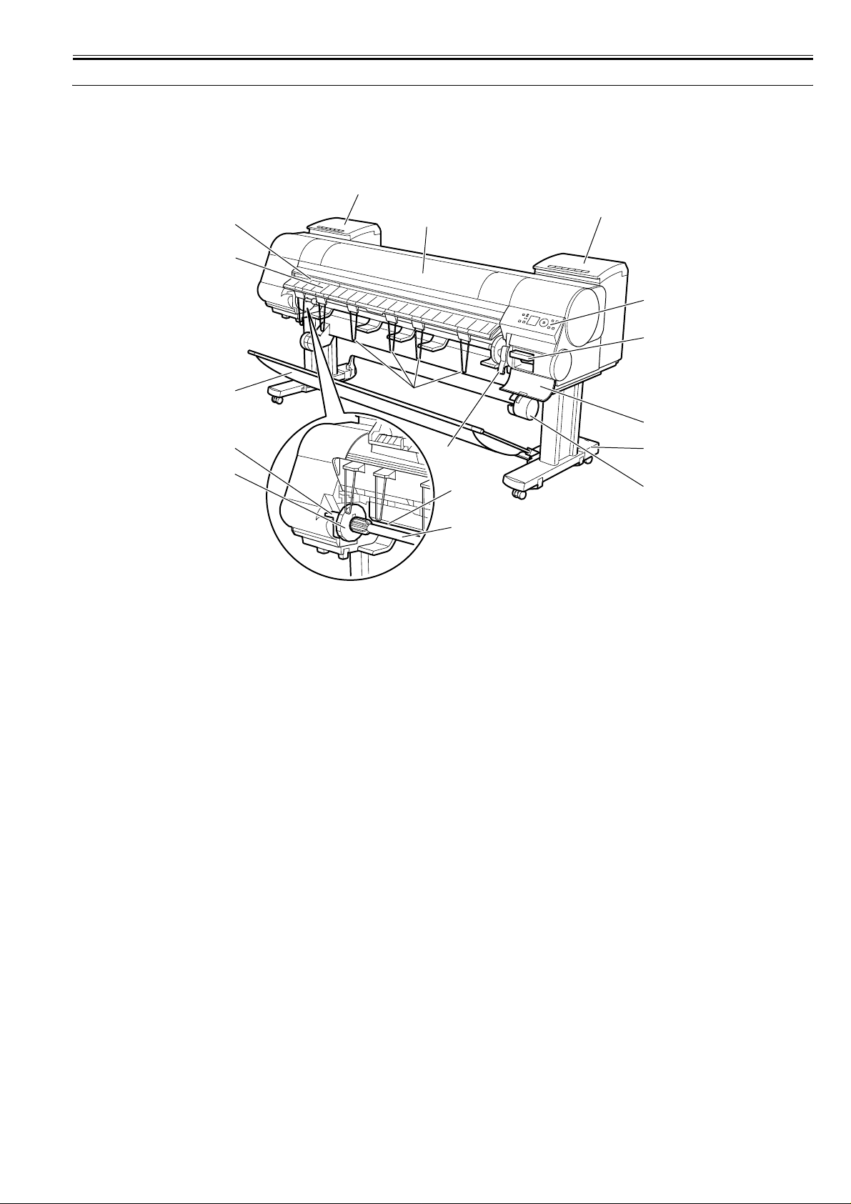
1.1 Product Overview
Chapter 1
1.1.1 Product Overview
iPF9000 / iPF9000S / iPF9100
This printer is a large-format printer that prints in a maximum width of 60 inches with high-speed photographic picture quality.
This printer is a stand-mounted type printer and is capable of output to either roll media or cut sheet.
[2]
[3]
[4]
[5]
[6]
[7]
[1]
[10]
[11]
[9]
[2]
0012-6197
[16]
[15]
[14]
[13]
[12]
F-1-1
[8]
1-1
Page 14
Chapter 1
[4]
[5]
[3]
[2]
[1]
[7]
[6]
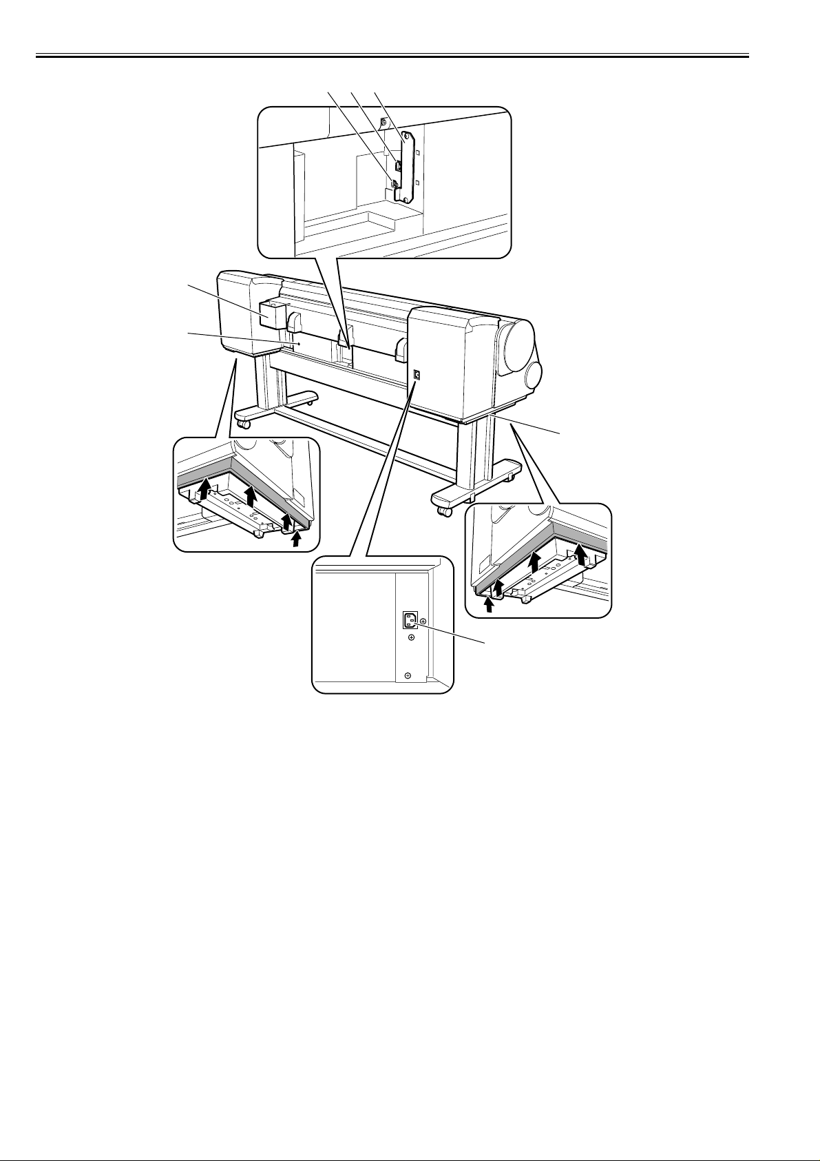
F-1-2
T-1-1
[1] Upper Cover [13] Stand
[2] Ink Tank Cover [14] Maintenance Cartridge Cover
[3] Ejection Slot [15] Maintenance Cartridge
[4] Ejection Guide [16] Operation Panel
[5] Output Stacker [17] Expansion Board Slot
[6] Roll Holder Slot [18] Ethernet Port
[7] Holder Stopper [19] USB Port
[8] Roll Holder [20] Accessory Pocket
[9] Paper Feed Slot [21] Media Take-up Unit Power Inlet
[10] Ejection Support [22] Power Supply Connector
[11] Release Lever [23] Carrying Handles
[12] Media Take-up Unit
1-2
Page 15

1.2 Features
Chapter 1
1.2.1 Features
iPF9000
- Media pass in widths up to 60 inches (1524 mm).
- Large ink tanks save the need for their replacement.
- Uninterrupted printing from subtanks.
- Two kinds of BK inks loaded concurrently to eliminate the need for their replacement.
- Hard disk drive mounted for greater ease of job management and for driving on night time.
- Media take-up unit supported as a standard feature.
- Basket (option) can be mounted concurrently with a media take-up unit.
- Durability will be added by maintenance kit.
- Large LCD panel displays more information and makes operations easier.
- High resolutions of 2400 x 1200 dpi maximum, coupled with the exceptionally light-fast, water-proof and ozone-proof 12-color pigment inks of MBK, BK,
PC, C, PM, M, Y, R, G, B, GY, and PGY, deliver high-quality photographic picture quality.
- USB2.0 high-speed interface and 10Base-T/100Base-TX in standard support of a TCP/IP network, plus optional support of IEEE1394.
- Barcodes printed on roll media make remaining roll media management possible.
- Borderless four-side printing support (roll media) removes laborious cutting work, easing the job of creating posters to a significant degree.
- High-speed printing with a 1-inch head for each color (1,280 nozzles), under bidirectional print control.
- Ink supply through tubing to a completely independent printhead and large-capacity ink tanks.
1.2.2 Features
iPF9100
- Media pass in widths up to 60 inches (1524 mm).
- Large ink tanks save the need for their replacement.
- Uninterrupted printing from subtanks.
- Two kinds of BK inks loaded concurrently to eliminate the need for their replacement.
- Hard disk drive mounted for greater ease of job management and for driving on night time.
- Media take-up unit supported as a standard feature.
- Basket (option) can be mounted concurrently with a media take-up unit.
- Durability will be added by maintenance kit.
- Large LCD panel displays more information and makes operations easier.
- High resolutions of 2400 x 1200 dpi maximum, coupled with the exceptionally light-fast, water-proof and ozone-proof 12-color pigment inks of MBK, BK, PC,
C, PM, M, Y, R, G, B, GY, and PGY, deliver high-quality photographic picture quality.
- USB2.0 high-speed interface and 10Base-T/100Base-TX in standard support of a TCP/IP network, plus optional support of IEEE1394.
- Barcodes printed on roll media make remaining roll media management possible.
- Borderless four-side printing support (roll media) removes laborious cutting work, easing the job of creating posters to a significant degree.
- High-speed printing with a 1-inch head for each color (1,280 nozzles), under bidirectional print control.
- Ink supply through tubing to a completely independent printhead and large-capacity ink tanks.
Functional enhancements new to this model include:
- Higher image quality
Use of abrasion-resistant inks (MBK, BK, PGY, GY) offers enhanced image durability.
0012-6215
0017-8108
The color calibration feature adds to the faithfulness of color reproduction.
1.2.3 Features
iPF9000S
- Media pass in widths up to 60 inches (1524 mm).
- Large ink tanks save the need for their replacement.
- Uninterrupted printing from subtanks.
- Two kinds of BK inks loaded concurrently to eliminate the need for their replacement.
- Hard disk drive mounted for greater ease of job management and for driving on night time.
- Media take-up unit supported as a standard feature.
- Basket (option) can be mounted concurrently with a media take-up unit.
- Durability will be added by maintenance kit.
- Large LCD panel displays more information and makes operations easier.
- High resolutions of 2400 x 1200 dpi maximu m, coupled with the exceptionally light-fast, water-proof and ozone-proof 8-color pigment inks of MBK, BK, PC,
C, PM, M, Y and GY, deliver high-quality photographic picture quality.
- USB2.0 high-speed interface and 10Base-T/100Base-TX in standard support of a TCP/IP network, plus optional support of IEEE1394.
- Barcodes printed on roll media make remaining roll media management possible.
- Borderless four-side printing support (roll media) removes laborious cutting work, easing the job of creating posters to a significant degree.
- High-speed printing with a 1-inch head for each color (1,280 nozzles), under bidirectional print control.
- Ink supply through tubing to a completely independent printhead and large-capacity ink tanks.
Functional enhancements new to this model include:
- Higher image quality
The color calibration feature adds to the faithfulness of color reprod uction.
- High printing productivity
The 8-color pigment inks system offers enhanced printing productivity.
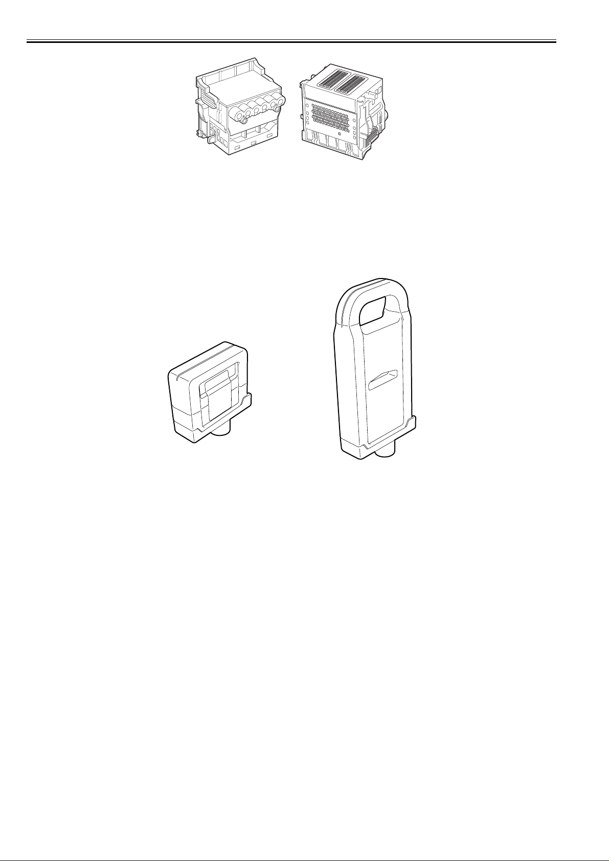
1.2.4 Printhead
iPF9000 / iPF9000S / iPF9100
0017-8109
0013-2742
The printhead that mounts on the carriage is an integrated six-color disposable printhead.
It has 2,560 nozzles for each color, comprising two trays of 1,280 nozzles each arranged in a zigzag pattern.
If print quality remains unimproved even after a specified cleaning operation, replace the printhead. Replacement about one year after the date of initial unpacking
is also recommended.
1-3
Page 16
Chapter 1
F-1-3
1.2.5 Ink tank
iPF9000 / iPF9100
Ink tanks are disposable.
The ink tanks come with 12 colors: mat black (MBK), black (BK), photocyan (PC), cyan (C), photomagenta (PM), magenta (M), yellow (Y), red (R), blue (B),
green (G), gray (GY) and photogray (PGY). Each of these inks are pigment ink.
The tanks are also available in two capacities: 330 mL and 700 mL.
Each tank is furnished with a notch for preventing incorrect installation, which will allow the tank to be installed only at the position marked in the right color.
An ink tank should be replaced when an ink tank replacement prompt message appears or when six months expire after the date of initial unpacking, whichever
occurs earlier.
F-1-4
0012-6218
1-4
Page 17
Chapter 1
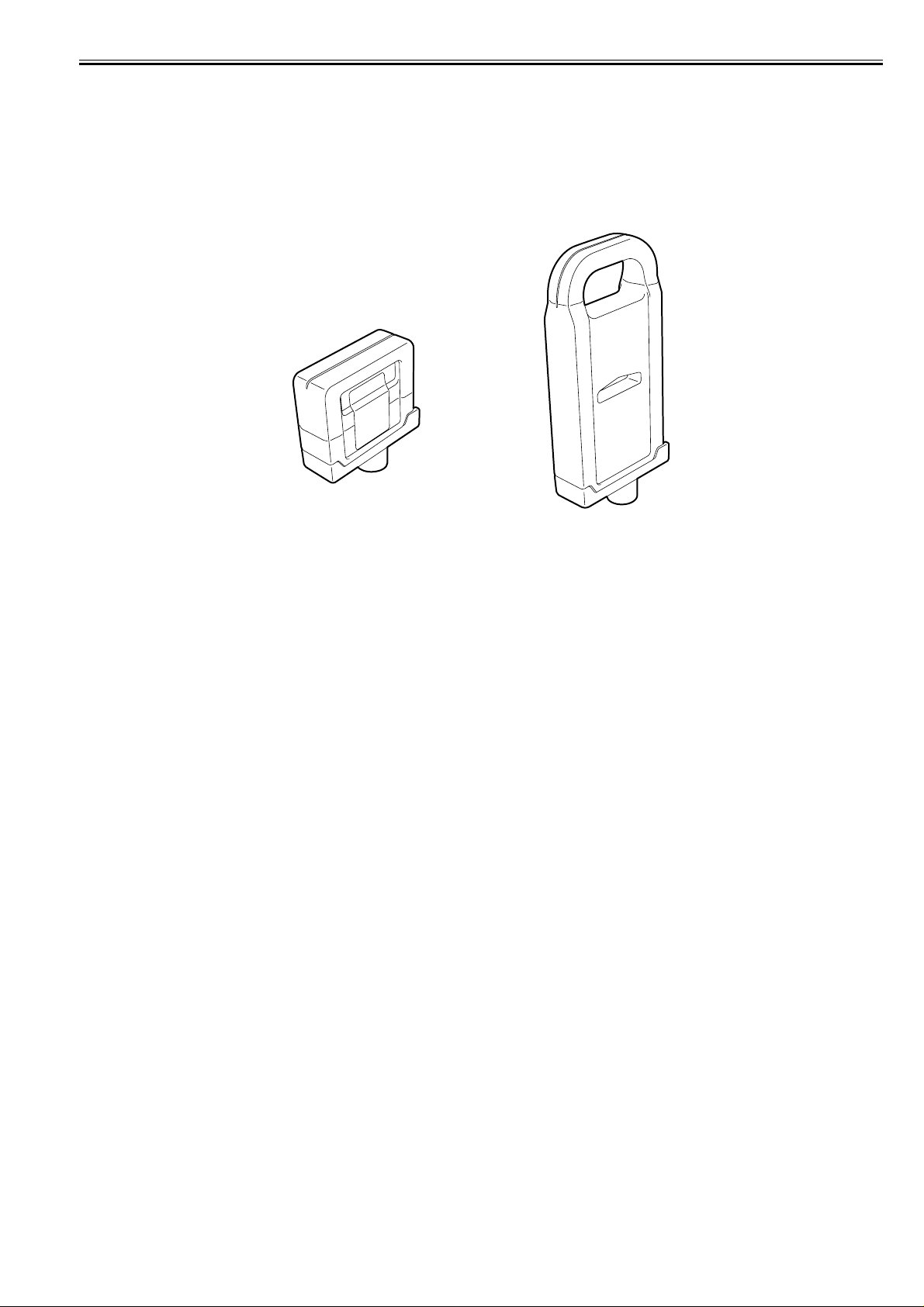
1.2.6 Ink tank
iPF9000S
0017-8112
Ink tanks are disposable.
The ink tanks come with 8 colors: mat black (MBK), black (BK), photocyan (PC), cyan (C), photomagenta (PM), magenta (M), yellow (Y) and gray (GY). Each
of these inks are pigment ink.
The tanks are also available in two capacities: 330 mL and 700 mL.
Each tank is furnished with a notch for preventing incorrect installation, which will allow the tank to be installed only at the position marked in the right color.
An ink tank should be replaced when an ink tank replacement prompt message appears or when six months expire after the date of initial unpacking, whichever
occurs earlier.
F-1-5
1-5
Page 18

Chapter 1
1.2.7 Cutter unit
iPF9000 / iPF9000S / iPF9100
0013-6369
The cutter unit that mounts on the carriage unit is disposable.
Replace the cutter unit when it gets dull.
F-1-6
1.2.8 Roll holder
iPF9000 / iPF9000S / iPF9100
The printer comes with a roll holder for paper tubes having an inside diameter of 2 inches as standard. It supports an optional roller holder for paper tubes having
an inside diameter of 3 inches.
0013-6371
Both roll holders clamp the paper tubes of roll media with an outside diameter of 150 mm or less from inside.
F-1-7
1.2.9 Stand
iPF9000 / iPF9000S / iPF9100
It is a stand that puts the printer. Equipped with casters so that the printer can be easily moved.
[1]
0017-8300
1-6
[2]
O N
F-1-8
T-1-2
[1] Stand [2] Stopper
Page 19

Chapter 1
1.2.10 Media take-up unit
iPF9000 / iPF9000S / iPF9100
0013-9216
Media take-up unit
The media take-up unit takes up roll media, ranging in width from 17 to 60 inches, on a 2 or 3-inch paper tube in roll form after they are printed by the host computer.
Taking up begins automatically when a sensor attached to the bottom of the stand detects a roll delivered after printing falling down due to the weight of a weight
roller.
Rolls may also be manually taken up by using a button on the media take-up unit.
The media take-up unit has an overload protection feature to prevent accidents while taking up rolls. (The feature will shut down the motor automatically when an
overload occurs while taking up a roll.)
Additional features of the media take-up unit include:
- An adapter may be installed to support a 3-inch paper tube.
- Rolls can be rewound by feeding them backward to visually check images.
- Weight rollers varying in length to suit specific roll widths ensure added takeup efficiency.
- The printer detects errors in the media take-up unit by itself.
- Linked with the printer's sleep mode.
[1]
[4]
[5]
[2]
[5]
[3]
F-1-9
T-1-3
[1] Left media take-up unit [4] Media take-up unit
[2] Rewind spool [5] 3-inch adapter
[3] Media take-up sensor
Weight
This weight consists of weight roll(7 pcs.)[1], weight flange(2 sets)[2] and weight joint[3].
[2]
[1]
[2]
[1]
[3]
[1]
[2]
F-1-10
[2]
1-7
Page 20
Chapter 1
1.2.11 Hard disk drive
iPF9000
0012-6687
Each print job received from the host computer is saved to the 40GB hard disk drive(parallel ATA connection) attache d to t he pr inter, so the printer can print the
job repeatedly as needed, without having to wait for its retransmission from the host computer.
Saving print jobs will offer the following benefits:
- Eased computer workload
A print job may be automatically preserved to the hard disk when printing or may be preserved to the hard disk without printing. A print job preserve d can be
printed in as many copies as needed without having to use the host computer.
- Reprinting after error occurrence
If the printer encounters errors, such as paper out, while printing a print job, it can resume the print operation as soon as the errors are cleared, without needing its
retransmission from the host computer.
- Higher print work eff iciency
Print jobs can be printed selectively or in a specified number of copies without using a host computer. Multiple print jobs can be printed batched. Unattended print
operations in the nighttime are also possible.
1.2.12 Hard disk drive
iPF9000S / iPF9100
Each print job received from the host computer is saved to the 80GB hard disk drive(serial ATA connection) attached to the printer, so the printer can print the job
repeatedly as needed, without having to wait for its retransmission from the host computer.
Saving print jobs will offer the following benefits:
- Eased computer workload
A print job may be automatically preserved to the hard disk when printing or may be preserved to the hard disk without printing. A print job preserve d can be
0017-8472
printed in as many copies as needed without having to use the host computer.
- Reprinting after error occurrence
If the printer encounters errors, such as paper out, while printing a print job, it can resume the print operation as soon as the errors are cleared, without needing its
retransmission from the host computer.
- Higher print work eff iciency
Print jobs can be printed selectively or in a specified number of copies without using a host computer. Multiple print jobs can be printed batched. Unattended print
operations in the nighttime are also possible.
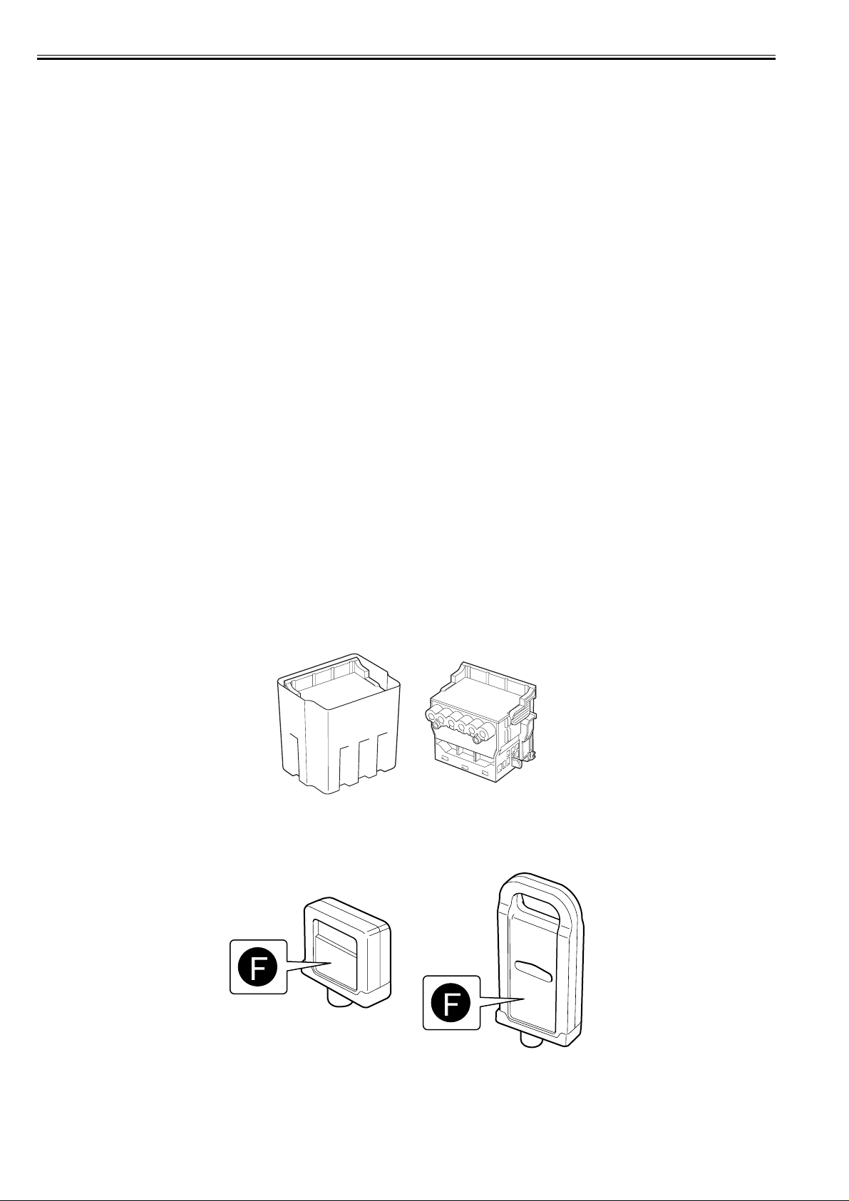
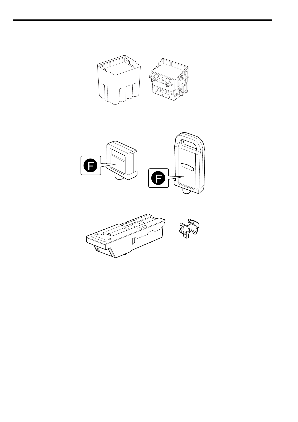
1.2.13 Consumables
iPF9000 / iPF9100
Printhead
The expendable printhead is the same as the one that comes with the printer.
F-1-11
Ink tanks
Expendable ink tanks contain 12 colors: mat black, black, photocyan, cyan, photomagenta, magenta, yellow, red, blue, green, gray and photogray. Each tank is
available in two capacities: 330 mL and 700 mL.
0012-6222
Usable for six months after unpacking.
F-1-12
Maintenance cartridge
The expendable maintenance cartridge is the same as the one that comes with the printer.
1-8
Page 21

F-1-13
Chapter 1
1-9
Page 22
Chapter 1
1.2.14 Consumables
iPF9000S
0017-8858
Printhead
The expendable printhead is the same as the one that comes with the printer.
F-1-14
Ink tanks
Expendable ink tanks contain 8 colors: mat black, black, photoc yan, cyan, photomagenta, magenta, yellow and gray. Each tank is available in two capacities: 330
mL and 700 mL.
Usable for six months after unpacking.
F-1-15
Maintenance cartridge
The expendable maintenance cartridge is the same as the one that comes with the printer.
F-1-16
1-10
Page 23

1.3 Product Specifications
Chapter 1
1.3.1 General Specifications
iPF9000
Type Bubblejet printer (stand model)
Feeding system Roll media: Manual (front loading)
Feeding capacity Roll media: 1 roll (up to 150 mm outside diameter)
Delivery method Forward delivery, face up
Sheet delivery capability 1 (loaded in a basket)
Cutter Automatic cross-cutter (round blade)
Type of media Plain Paper,Plain Paper(High Quality),Plain Paper(High Grade),
Supported thickness 0.07 mm to 0.8 mm
Media size (Roll media) Width: 203.2 mm (8") to 1524 mm (60")
Media size (Cut sheet) Width: 203.2 mm (8") to 1524 mm (60")
Cut media: Paper tray (front loading)
Standard roll holder: Paper tube, 50.8 mm (2") inside diameter
Cut media: 1
Recycled Coated Paper, Coated Paper ,Heavyweigh t Coated Paper ,Extra
Heavyweight Coated Paper, Premium Matte Paper,Glossy Photo
Paper,Semi-Glossy Photo Paper,Heavyweight Glossy Photo
Paper,Heavyweight SemiGlos Photo Paper,Synthetic Paper,Adhesive
Synthetic Paper,Backlit Film,Backprint Film,Flame-Resistant
Cloth,Fabric Banner,Thin Fabric Banner,Proofing Paper,Fine Art
Photo,Fine Art Heavyweight Photo,Fine Art Textured,Fine Art
Watercolor,Fine Art Block Print,Canvas Matte,Canvas SemiGlossy,Japanese Paper Washi, Colored Coated Paper, CAD Tracing
Paper,CAD Translucent Matte Film,CAD Clear Film
Length: 203.2 mm (8") to 1524 mm (60")
*Outer diameter of roll :150mm or less
Length: 203.2 mm (8") to 1600 mm (63")
0012-6224
Printable area (Roll media) Internal area, excluding a 5-mm top, bottom and left and right margins.
Printable area (Cut sheet) Internal area, excluding a 5-mmn top margin, a 23-mm bottom margin
Printing recommendation area
(Roll media)
Printing recommendation area
(Cut sheet)
Margins (Roll media) Roll media: 5 mm for top, bottom and left and right margins
Margins (Cut sheet) 20 mm top margin, 23- mm bottom margin and 5- mm left an d right
Emulation None
Interface USB 2.0
Printhead/Ink Tank type Independent printhead/ink tanks
Printhead PF-02
Ink tank PFI-301 MBK/BK/PC/C/PM/M/Y/R/G/B/GY/PGY
Detection functions (Cover
system)
Detection functions (Ink passage
system)
Detection functions (Carriage
system)
Detection functions (Paper path
system)
* The printable area may vary with each type of paper media used.
and 3-mm left and right margins.
* The printable area may vary with each type of paper media used.
Internal area, excluding a 20 mm top margin, a 23-mm bottom margin
and 5-mm left and right margins.
Internal area, excluding a 20 mm top margin, a 23-mm bottom margin
and 5-mm left and right margins.
Borderless roll media: 0 mm for top, bottom and left and right margins
margins
Network (10BASE-T/100BASE-TX)
IEEE1394 (optional)
Structure: Integrated six-color assembly
Number of nozzles: 2,560 for ach color
PFI-701 MBK/BK/PC/C/PM/M/Y/R/G/B/GY/PGY
Ink type: Pigment ink
Ink tank capacity: PFI-301 330 mL, PFI-701 700 mL
Cover open/closed detection: Yes
Left and right ink tank cover open/closed detection: Yes
Ink tank presence/absence detection: Yes
Remaining ink level detection: Yes
Maintenance cartridge presence/absence detection: Yes
Used ink tank full detection: Yes
Printhead presence/absence detection: Yes
Carriage position detection: Yes
Carriage home position detection: Yes
Carriage cover open/closed detection: Yes
Carriage temperature detection: Yes
Printhead height detection: Yes
Non-discharging nozzle detection: Yes
Non-discharging nozzle backup feature: Yes
Paper presence/absence detection: Yes
Paper width detection: Yes
Skew detection: Yes
Paper release lever position detection: Yes
Remaining roll media detection: Yes
Feed roller rotation detection: Yes
1-11
Page 24
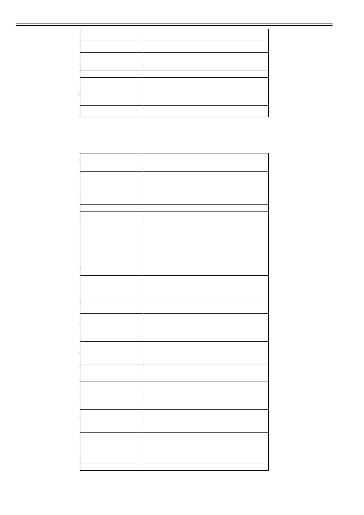
Chapter 1
Operating noise Operating: Approx. 52dB (A) or less
Operating environment Operating temperature: 5oC to 35oC
Print quality guaranteed
environment
Power supply AC100 to 240V, 1.6A, 50/60Hz
Power consumption (Maximum) Maximum: 190W
Power consumption Sleep mode: 6W or less (with IEEE1394 installed, 9W or less)
Printer unit dimensions
(WxDxH)
Weight Printer alone: Approx. 130kg
1.3.2 Product Specifications
iPF9100
Type Bubble jet large-sized paper printer (stand model)
Feeding system Roll media: Manual (front loading)
Feeding capacity - Roll media
Delivery method Forward delivery, face up
Sheet delivery capability 1 sheet (using the outout stacker of the stand)
Cutter Automatic cross-cutter (round blade)
Type of media Plain Paper, Plain Paper (High Quality), Plain Paper (High Grade),
Supported thickness 0.07mm to 0.8mm
Media size (Roll media) Width: 254mm (10") to 1524mm (60")
Media size (Cut sheet) Width: 203mm (8") to 1524mm (60")
Printable area (Roll media) Internal area, excluding a 5-mm top, bottom and left and right margins.
Printable area (Cut sheet) Internal area, excluding a 5-mm top margin, a 23-mm bottom margin and
Printing recommendation area
(Roll media)
Printing recommendation area
(Cut sheet)
Borderless printing * Roll media only
Memory 640MB
Firmware Flash ROM (update from USB or Ethernet, IEEE1394)
Emulation None
Interface USB 2.0 Hi-Speed
Operation panel LCD (160 X 128 dots), 12 keys, 5 LEDs
Printhead/Ink Tank type Printhead and separate ink tanks
Idle: Approx. 35dB (A) or less
Relative humidity: 10% to 90%RH
Guaranteed print quality temperature: 15oC to 30oC
Relative humidity: 10% to 80%RH
Powered off: 1W or less
2299mm x 766mm x 1144mm
Stand installed: Approx. 165kg
Cut sheet: Paper tray (front loading)
One roll at the back/Outer diameter of roll: 150 mm or less/Inner
diameter of paper tube: 3 inches(standard roll holder )
- Cut sheet
1 sheet
Coated Paper, Heavyweight Coated Paper, Premium Matte Paper,
Glossy Photo Paper, Semi-Glossy Photo Paper, Backlit Film, Backprint
Film, Flame-Resistant Cloth, Fine Art Photo, Fine Art Heavyweight
Photo, Fine Art Textured, Canvas Matte, Premium Coated Paper,
Graphic Canvas, Durable Backlit Film, Durable Banner, Matt Coated
Paper, Extra Matt Coated Pa per, Opaque Pap er, Hi Res Graphi c Paper,
Prem Art Paper Embossed, Prem Art Paper Smooth, Hi Res Barrier
Paper, Scrim Banner, Uni Opaque Backlit Film, Roll-Up Film , Water
Res Art Canvas, Adhesive Matt Vinyl Stretch
Length: 203mm (8") to 18m (709")
* Outer diameter of roll :150mm or less
* The maximum amount of length may vary by the using operating
system or the applications.
Length: 203mm (8") to 1600mm (63")
* The printable area may vary with each type of paper media used.
5-mm left and right margins.
* The printable area may vary with each type of paper media used.
Internal area, excluding a 20-mm top margin, a 5-mm bottom margin and
5-mm left and right margins.
Internal area, excluding a 20-mm top margin, a 23-mm bottom margin
and 5-mm left and right margins.
width: 254mm(10"), 355.6mm(14"), 406.4mm(16"), 515mm , 594mm,
609.6mm(24"), 841mm, 914.4mm(36"), 1030mm, 1066.8mm(42")
Increase of memory: none
- Printer description language
GARO (Graphic Arts language with Raster Operation)
Network (10BASE-T/100BASE-TX)
IEEE1394 (option)
- Panel language
English
- Message language
English, German, French, Italian, Spanish, Chinese, Korean, Russianand
and Japanese
0017-8307
1-12
Page 25

Chapter 1
Printhead PF-03
Ink tank PFI-301 C/M/Y/PC/PM/R/G/B
Detection functions (Cover
system)
Detection functions (Ink passage
system)
Detection functions (Carriage
system)
Detection functions (Paper path
system)
Operating noise Operating: Approx. 51dB (A) or less
Operating environment Temperature: 15 to 35 degrees centigrade
Print quality guaranteed
environment
Power supply 100-240 VAC (50/60 Hz)
Power consumption (Maximum) During printing: Max. 190 W
Power consumption In power save (sleep) mode:
Printer unit dimensions
(WxDxH)
Weight Approx. 163 kg (with stand)
Structure: Integrated six-color assembly
Number of nozzles: 2,560 for each color
PFI-701 C/M/Y/PC/PM/R/G/B
PFI-302 BK/MBK/GY/PGY
PFI-702 BK/MBK/GY/PGY
Ink type: Pigment ink
Ink tank capacity: PFI-301/302 330 ml, PFI-701/702 700 ml
Cover open/closed detection: Yes
Left and right ink tank cover open/closed detection: Yes
Ink tank presence/absence detection: Yes
Remaining ink level detection: Yes
Maintenance cartridge presence/absence detection: Yes
Used ink tank full detection: Yes
Printhead presence/absence detection: Yes
Carriage position detection: Yes
Carriage home position detection: Yes
Carriage cover open/closed detection: Yes
Carriage temperature detection: Yes
Printhead height detection: Yes
Non-discharging nozzle detection: Yes
Non-discharging nozzle backup feature: Yes
Paper presence/absence detection: Yes
Paper width detection: Yes
Skew detection: Yes
Paper release lever position detection: Yes
Remaining roll media detection: Yes
Feed roller rotation detection: Yes
Standby: Approx. 35dB (A) or less
Humidity: 10% to 90%RH
Temperature: 15 to 30 degrees centigrade
Humidity: 10% to 80%RH
100-120 VAC : 5W or less (When IEEE1394 board installed, 1 0W or
less)
220-240 VAC : 6W or less (When IEEE1394 board installed, 1 1W or
less)
During standby: 1 W or less
2299mm x 766mm x 1144mm (with stand)
1.3.3 Product Specifications
iPF9000S
Type Bubble jet large-sized paper printer (stand model)
Feeding system Roll media: Manual (front loading)
Feeding capacity - Roll media
Delivery method Forward delivery, face up
Sheet delivery capability 1 sheet (using the outout stacker of the stand)
Cutter Automatic cross-cutter (round blade)
Type of media Plain Paper, Plain Paper (High Quality), Plain Paper (High Grade),
Supported thickness 0.07mm to 0.8mm
Media size (Roll media) Width: 254mm (10") to 1524mm (60")
Media size (Cut sheet) Width: 203mm (8") to 1524mm (60")
Cut sheet: Paper tray (front loading)
One roll at the back/Outer diameter of roll: 150 mm or less/Inner
diameter of paper tube: 3 inches(standard roll holder )
- Cut sheet
1 sheet
Coated Paper, Heavyweight Coated Paper, Premium Matte Paper,
Glossy Photo Paper, Semi-Glossy Photo Paper, Backlit Film, Backpri nt
Film, Flame-Resistant Cloth, Fine Art Photo, Fine Art Heavyweight
Photo, Fine Art Textured, Canvas Matte, Premium Coated Paper,
Graphic Canvas, Durable Backlit Film, Durable Banner, Matt Coated
Paper, Extra Matt Coated Pa per, Opaque Pap er, Hi Res Graphic P aper,
Prem Art Paper Embossed, Prem Art Paper Smooth, Hi Res Barrier
Paper, Scrim Banner, Uni Opaque Backlit Film, Roll-Up Film , Water
Res Art Canvas, Adhesive Matt Vinyl Stretch
Length: 203mm (8") to 18m (709")
* Outer diameter of roll :150mm or less
* The maximum amount of length may vary by the using operating
system or the applications.
Length: 203mm (8") to 1600mm (63")
0017-8309
1-13
Page 26

Chapter 1
Printable area (Roll media) Internal area, excluding a 5-mm top, bottom and left and right margins.
Printable area (Cut sheet) Internal area, excluding a 5-mm top margin, a 23-mm bottom margin and
Printing recommendation area
(Roll media)
Printing recommendation area
(Cut sheet)
Borderless printing * Roll media only
Memory 640MB
Firmware Flash ROM (update from USB or Ethernet, IEEE1394)
Emulation None
Interface USB 2.0 Hi-Speed
Operation panel LCD (160 X 128 dots), 12 keys, 5 LEDs
Printhead/Ink Tank type Printhead and separate ink tanks
Printhead PF-03
Ink tank PFI-301 BK/MBK/C/M/Y/PC/PM/GY
Detection functions (Cover
system)
Detection functions (Ink passage
system)
Detection functions (Carriage
system)
Detection functions (Paper path
system)
Operating noise Operating: Approx. 51dB (A) or less
Operating environment Temperature: 15 to 35 degrees centigrade
Print quality guaranteed
environment
Power supply 100-240 VAC (50/60 Hz)
Power consumption (Maximum) During printing: Max. 190 W
Power consumption In power save (sleep) mode:
Printer unit dimensions
(WxDxH)
Weight Approx. 157 kg (with stand)
* The printable area may vary with each type of paper media used.
5-mm left and right margins.
* The printable area may vary with each type of paper media used.
Internal area, excluding a 20-mm top margin, a 5-mm bottom margin and
5-mm left and right margins.
Internal area, excluding a 20-mm top margin, a 23-mm bottom margin
and 5-mm left and right margins.
width: 254mm(10"), 355.6mm(14"), 406.4mm(16"), 515mm , 594mm,
609.6mm(24"), 841mm, 914.4mm(36"), 1030mm, 1066.8mm(42")
Increase of memory: none
- Printer description language
GARO (Graphic Arts language with Raster Operation)
Network (10BASE-T/100BASE-TX)
IEEE1394 (option)
- Panel language
English
- Message language
English, German, French, Italian, Spanish, Chinese, Korean, Russianand
and Japanese
Structure: Integrated six-color assembly
Number of nozzles: 2,560 for each color
PFI-701 BK/MBK/C/M/Y/PC/PM/GY
Ink type: Pigment ink
Ink tank capacity: PFI-301 330 ml, PFI-701 700 ml
Cover open/closed detection: Yes
Left and right ink tank cover open/closed detection: Yes
Ink tank presence/absence detection: Yes
Remaining ink level detection: Yes
Maintenance cartridge presence/absence detection: Yes
Used ink tank full detection: Yes
Printhead presence/absence detection: Yes
Carriage position detection: Yes
Carriage home position detection: Yes
Carriage cover open/closed detection: Yes
Carriage temperature detection: Yes
Printhead height detection: Yes
Non-discharging nozzle detection: Yes
Non-discharging nozzle backup feature: Yes
Paper presence/absence detection: Yes
Paper width detection: Yes
Skew detection: Yes
Paper release lever position detection: Yes
Remaining roll media detection: Yes
Feed roller rotation detection: Yes
Standby: Approx. 35dB (A) or less
Humidity: 10% to 90%RH
Temperature: 15 to 30 degrees centigrade
Humidity: 10% to 80%RH
100-120 VAC : 5W or less (When IEEE1394 board installed, 10W or
less)
220-240 VAC : 6W or less (When IEEE1394 board installed, 11W or
less)
During standby: 1 W or less
2299mm x 766mm x 1144mm (with stand)
1.4 Detailed Specifications
1.4.1 Printing mode
iPF9000
1-14
0012-6230
Page 27

T-1-4
Media Type Print
Plain Paper
Plain Paper(High Quality)
Plain Paper(High Grade)
Recycled Coated Paper
Coated Paper
Heavyweight Coated Paper
Extra Heavyweight Coated Paper
Premium Matte Paper
Glossy Photo Paper
Semi-Glossy Photo Paper
Heavyweight Glossy Photo Paper
Heavyweight SemiGlos Photo Paper
Synthetic Paper
Adhesive Synthetic Paper
Backlit Film
Backprint Film
Flame-Resistant Cloth
Fabric Banner
Thin Fabric Banner
Proofing Paper
Fine Art Photo
Fine Art Heavyweight Photo
Fine Art Textured
Fine Art Watercolor
Fine Art Block Print
Canvas Matte
Canvas Semi-Glossy
Japanese Paper Washi
Colored Coated Paper Image standard 300 1200x1200 4 Bi-directional
CAD Tracing Paper
CAD Translucent Matte Film
CAD Clear Film
Priority
Image draft 300 1200x1200 2 Bi-directional
Line drawing
/Text
Office
document
Image standard 300 1200x1200 4 Bi-directional
Image standard 600 1200x1200 6 Bi-directional
Line drawing
/Text
Print Quality Processing
standard 300 1200x1200 4 Bi-directional
High 600 2400x1200 8 Bi-directional
draft 600 1200x1200 2 Bi-directional
standard 600 1200x1200 4 Bi-directional
standard 600 1200x1200 4 Bi-directional
High 600 2400x1200 8 Bi-directional
Highest 600 2400x1200 12 Bi-directional
High 600 2400x1200 8 Bi-directional
Highest 600 2400x1200 16 Bi-directional
High 600 2400x1200 8 Bi-directional
draft 600 1200x1200 2 Bi-directional
standard 600 1200x1200 4 Bi-directional
High 600 2400x1200 8 Bi-directional
resolution
(dpi)
Print resolution
(dpi)
Print
pass
Printing direction
(*1)
Chapter 1
*1 Uni-directional can be selected optionally from the printer driver.
1.4.2 Print Speed and Direction
iPF9000S
0017-8148
1-15
Page 28

Chapter 1
Plain Paper/
Recycled Paper
T-1-5
Media Type Print Priority
Plain Paper/Recycled Paper Office Document Standard 4 Bi-directional 1200x1200 MBK
Line Document/
Text
Image Draft 2 Bi-directional 1200x1200 MBK
Plain Paper (High Quality) Office Document Standard 4 Bi-directional 1200x1200 MBK
Line Document/
Text
Image Draft 2 Bi-directional 1200x1200 MBK
Plain Paper (High Grade) Office Document Standard 4 Bi-directional 1200x1200 MBK
Line Document/
Text
Image Draft 2 Bi-directional 1200x1200 MBK
Economy Bond Paper Office Document Standard 4 Bi-directional 1200x1200 MBK
Line Document/
Text
Image Draft 2 Bi-directional 1200x1200 MBK
Universal Bond Paper Office Document Standard 4 Bi-directional 1200x1200 MBK
Line Document/
Text
Image Draft 2 Bi-directional 1200x1200 MBK
Standard Paper 1569B 80g Office Document Standard 4 Bi-directional 1200x1200 MBK
Line Document/
Text
Image Draft 2 Bi-directional 1200x1200 MBK
Standard Paper 1570B 90g Office Document Standard 4 Bi-directional 1200x1200 MBK
Line Document/
Text
Image Draft 2 Bi-directional 1200x1200 MBK
Print
Quality
Draft 2 Bi-directional 1200x1200 MBK
Standard 4 Bi-directional 1200x1200 MBK
Standard 4 Bi-directional 1200x1200 MBK
High 8 Bi-directional 2400x1200 MBK
Draft 2 Bi-directional 1200x1200 MBK
Standard 4 Bi-directional 1200x1200 MBK
Standard 4 Bi-directional 1200x1200 MBK
High 8 Bi-directional 2400x1200 MBK
Draft 2 Bi-directional 1200x1200 MBK
Standard 4 Bi-directional 1200x1200 MBK
Standard 4 Bi-directional 1200x1200 MBK
High 8 Bi-directional 2400x1200 MBK
Draft 2 Bi-directional 1200x1200 MBK
Standard 4 Bi-directional 1200x1200 MBK
Standard 4 Bi-directional 1200x1200 MBK
High 8 Bi-directional 2400x1200 MBK
Draft 2 Bi-directional 1200x1200 MBK
Standard 4 Bi-directional 1200x1200 MBK
Standard 4 Bi-directional 1200x1200 MBK
High 8 Bi-directional 2400x1200 MBK
Draft 2 Bi-directional 1200x1200 MBK
Standard 4 Bi-directional 1200x1200 MBK
Standard 4 Bi-directional 1200x1200 MBK
High 8 Bi-directional 2400x1200 MBK
Draft 2 Bi-directional 1200x1200 MBK
Standard 4 Bi-directional 1200x1200 MBK
Standard 4 Bi-directional 1200x1200 MBK
High 8 Bi-directional 2400x1200 MBK
Print-
Pass
Printing Direction
Print
Resolution
(dpi)
Used BK
ink
1-16
Page 29

Chapter 1
Media Type Print Priority
Coated Paper Coated Paper Image Standard 4 Bi-directional 1200x1200 MBK
Heavyweight Coated Paper Image Standard 4 Bi-directional 1200x1200 MBK
Premium Matte Paper Image Standard 6 Bi-directional 1200x1200 MBK
Extra Heavyweight Coated Paper Image Standard 4 Bi-directional 1200x1200 MBK
Recycled Coated Paper Image Standard 4 Bi-directional 1200x1200 MBK
Colored Coated Paper Image Standard 4 Bi-directional 1200x1200 MBK
Premium Coated Paper Image Standard 4 Bi-directional 1200x1200 MBK
LightWeight Coated Paper J80270 90g Image Standard 4 Bi-directional 1200x1200 MBK
High Resolution Barrier Paper 180g Image Standard 4 Bi-directional 1200x1200 MBK
Matt Coated Paper 9171 120g Image Standard 4 Bi-directional 1200x1200 MBK
Extra Matt Coated Paper 7215 180g Image Standard 4 Bi-directional 1200x1200 MBK
Opaque Paper White 120g Image Standard 4 Bi-directional 1200x1200 MBK
Matt Coated Paper 140g Image Standard 4 Bi-directional 1200x1200 MBK
Photo Realistic Paper 210g Image Standard 4 Bi-directional 1200x1200 MBK
LightWeight Coated Paper J80270 90g Image Standard 4 Bi-directional 1200x1200 MBK
Print
Quality
High 8 Bi-directional 2400x1200 MBK
Highest 12 Bi-directional 2400x1200 MBK
High 8 Bi-directional 2400x1200 MBK
Highest 12 Bi-directional 2400x1200 MBK
High 8 Bi-directional 2400x1200 MBK
Highest 16 Bi-directional 2400x1200 MBK
High 8 Bi-directional 2400x1200 MBK
Highest 12 Bi-directional 2400x1200 MBK
High 8 Bi-directional 2400x1200 MBK
Highest 12 Bi-directional 2400x1200 MBK
High 8 Bi-directional 2400x1200 MBK
High 8 Bi-directional 2400x1200 MBK
Highest 12 Bi-directional 2400x1200 MBK
High 8 Bi-directional 2400x1200 MBK
Highest 12 Bi-directional 2400x1200 MBK
High 8 Bi-directional 2400x1200 MBK
Highest 12 Bi-directional 2400x1200 MBK
High 8 Bi-directional 2400x1200 MBK
Highest 12 Bi-directional 2400x1200 MBK
High 8 Bi-directional 2400x1200 MBK
Highest 12 Bi-directional 2400x1200 MBK
High 8 Bi-directional 2400x1200 MBK
Highest 12 Bi-directional 2400x1200 MBK
High 8 Bi-directional 2400x1200 MBK
Highest 12 Bi-directional 2400x1200 MBK
High 8 Bi-directional 2400x1200 MBK
Highest 12 Bi-directional 2400x1200 MBK
High 8 Bi-directional 2400x1200 MBK
Highest 12 Bi-directional 2400x1200 MBK
Print-
Pass
Printing Direction
Print
Resolution
(dpi)
Used BK
ink
1-17
Page 30

Chapter 1
Media Type Print Priority
Photo Paper Glossy Photo Paper Image Standard 6 Bi-directional 1200x1200 PBK
Semi-Glossy Photo Paper Image Standard 6 Bi-directional 1200x1200 PBK
Heavyweight Glossy Photo Paper 2 Image Standard 6 Bi-directional 1200x1200 PBK
Heavywght SemiGlos Photo Paper 2 Image Standard 6 B i-directional 1200x1200 PBK
Poster Semi-Glossy Photo Paper Image Standard 6 Bi-directional 1200x1200 PBK
Premium RC Photo Luster , 10 mil Image Standard 6 Bi-directional 1200x1200 PBK
Instant Dry Papers Glossy 200g Image Standard 6 Bi-directional 1200x1200 PBK
Instant Dry Papers Satin 200g Image Standard 6 Bi-directional 1200x1200 PBK
Photo Paper High Glossy 250g Image Standard 6 Bi-directional 1200x1200 PBK
Photo Paper Semi Matt 250g Image Standard 6 Bi-directional 1200x12 00 PBK
Photo Paper Satin 240g Image Standard 6 Bi-directional 1200x1200 PBK
Photo Paper Pearl 260g Image Standard 6 Bi-directional 1200x1200 PBK
Print
Quality
High 8 Bi-directional 2400x1200 PBK
Highest 16 Bi-directional 2400x1200 PBK
High 8 Bi-directional 2400x1200 PBK
Highest 16 Bi-directional 2400x1200 PBK
High 8 Bi-directional 2400x1200 PBK
Highest 16 Bi-directional 2400x1200 PBK
High 8 Bi-directional 2400x1200 PBK
Highest 16 Bi-directional 2400x1200 PBK
High 8 Bi-directional 2400x1200 PBK
Highest 16 Bi-directional 2400x1200 PBK
High 8 Bi-directional 2400x1200 PBK
Highest 16 Bi-directional 2400x1200 PBK
High 8 Bi-directional 2400x1200 PBK
Highest 16 Bi-directional 2400x1200 PBK
High 8 Bi-directional 2400x1200 PBK
Highest 16 Bi-directional 2400x1200 PBK
High 8 Bi-directional 2400x1200 PBK
Highest 16 Bi-directional 2400x1200 PBK
High 8 Bi-directional 2400x1200 PBK
Highest 16 Bi-directional 2400x1200 PBK
High 8 Bi-directional 2400x1200 PBK
Highest 16 Bi-directional 2400x1200 PBK
High 8 Bi-directional 2400x1200 PBK
Highest 16 Bi-directional 2400x1200 PBK
Print-
Pass
Printing Direction
Print
Resolution
(dpi)
Used BK
ink
1-18
Page 31

Chapter 1
Media Type Print Priority
Art Paper Fine Art Photo Image Standard 6 Bi-directional 1200x1200 MBK
Fine Art Heavyweight Photo Image Standard 6 Bi-directional 1200x1200 MBK
Fine Art Textured Image Standard 6 Bi-directional 1200x1200 MBK
Canvas Matte Image Standard 6 Bi-directional 1200x1200 MBK
Fine Art Block Print Image Standard 6 Bi-directional 1200x1200 MBK
Fine Art Watercolor Image Standard 6 Bi-directional 1200x1200 MBK
Japanese Paper Washi Image Standard 6 Bi-directional 1200x1200 MBK
Graphic Matte Canvas Image Standard 6 Bi-directional 1200x1200 MBK
Art Paper Smooth 225g Image Standard 6 Bi-directional 1200x1200 MBK
Art Paper Embossed 225g Image Standard 6 Bi-directional 1200x1200 MBK
Art Paper Extra Smooth 250g Image Standard 6 Bi-directional 1200x1200 MBK
Water Resistant Paper Art Canvas Image Standard 6 Bi-directional 1200x1200 MBK
Proofing Paper Proofing Paper Image Standard 6 Bi-directional 1200x1200 PBK
Professional Proof and Photo Glossy 195g Image Standard 6 Bi-directional 1200x1200 PBK
Professional Proof and Photo Semiglossy
195g
Professional Proof and Photo Semigloss
255g
Film Paper Backlit Film Image Standard 8 Bi-directional 1200x1200 MBK
Backprint Film Image Standard 8 Bi-directional 1200x1200 PBK
Outdoor Backlit (Durable Backlit Film/
9578)
Pop-up Gloss Film Image Standard 8 Bi-directional 2400x1200 PBK
Universal Opaque White Film Image Standard 8 Bi-directional 2400x1200 PBK
Image Standard 6 Bi-directional 1200x1200 PBK
Image Standard 6 Bi-directional 1200x1200 PBK
Image Standard 8 Bi-directional 1200x1200 MBK
Print
Quality
High 8 Bi-directional 2400x1200 MBK
Highest 16 Bi-directional 2400x1200 MBK
High 8 Bi-directional 2400x1200 MBK
Highest 16 Bi-directional 2400x1200 MBK
High 8 Bi-directional 2400x1200 MBK
Highest 16 Bi-directional 2400x1200 MBK
High 8 Bi-directional 2400x1200 MBK
Highest 16 Bi-directional 2400x1200 MBK
High 8 Bi-directional 2400x1200 MBK
Highest 16 Bi-directional 2400x1200 MBK
High 8 Bi-directional 2400x1200 MBK
Highest 16 Bi-directional 2400x1200 MBK
High 8 Bi-directional 2400x1200 MBK
Highest 16 Bi-directional 2400x1200 MBK
High 8 Bi-directional 2400x1200 MBK
Highest 16 Bi-directional 2400x1200 MBK
High 8 Bi-directional 2400x1200 MBK
Highest 16 Bi-directional 2400x1200 MBK
High 8 Bi-directional 2400x1200 MBK
Highest 16 Bi-directional 2400x1200 MBK
High 8 Bi-directional 2400x1200 MBK
Highest 16 Bi-directional 2400x1200 MBK
High 8 Bi-directional 2400x1200 MBK
Highest 16 Bi-directional 2400x1200 MBK
High 8 Bi-directional 2400x1200 PBK
Highest 16 Bi-directional 2400x1200 PBK
High 8 Bi-directional 2400x1200 PBK
Highest 16 Bi-directional 2400x1200 PBK
High 8 Bi-directional 2400x1200 PBK
Highest 16 Bi-directional 2400x1200 PBK
High 8 Bi-directional 2400x1200 PBK
Highest 16 Bi-directional 2400x1200 PBK
High 12 Bi-directional 2400x1200 MBK
Highest 16 Bi-directional 2400x1200 MBK
High 12 Bi-directional 2400x1200 PBK
Highest 16 Bi-directional 2400x1200 PBK
High 12 Bi-directional 2400x1200 MBK
Highest 16 Bi-directional 2400x1200 MBK
High 16 Bi-directional 2400x1200 PBK
High 16 Bi-directional 2400x1200 PBK
Print-
Pass
Printing Direction
Print
Resolution
(dpi)
Used BK
ink
1-19
Page 32

Chapter 1
Media Type Print Priority
Matt Film
Paper
Thin Fabric
Banner
Synthetic
Paper
Adhesive Matt
Paper
CAD CAD Tracing Paper Line Document/
Scrim Banner 370g Image Standard 6 Bi-directional 1200x1200 MBK
Adhesive Matt Stretch Vinyl Image Standard 6 Bi-directional 1200x1200 MBK
Flame-Resistant Cloth Image Standard 6 Bi-directional 1200x1200 MBK
Fabric Banner Image Standard 6 Bi-directional 1200x1200 MBK
Thin Fabric Banner Image Standard 6 Bi-directional 1200x1200 MBK
Synthetic Paper Image Standard 6 Bi-directional 1200x1200 MBK
Adhesive Synthetic Paper Image Standard 6 Bi-directional 1200x1200 MBK
Outdoor Polypropylene (Durable Banner) Image Standard 6 Bi-directional 1200x1200 MBK
High Resolution Graphic Paper Self ADH Image Standard 6 Bi-directional 1200x1200 MBK
Text
CAD Clear Film Line Document/
CAD Translucent Matte Film Line Document/
Text
Text
Print
Quality
High 8 Bi-directional 2400x1200 MBK
Highest 16 Bi-directional 2400x1200 MBK
High 8 Bi-directional 2400x1200 MBK
Highest 16 Bi-directional 2400x1200 MBK
High 8 Bi-directional 2400x1200 MBK
Highest 16 Bi-directional 2400x1200 MBK
High 8 Bi-directional 2400x1200 MBK
Highest 16 Bi-directional 2400x1200 MBK
High 8 Bi-directional 2400x1200 MBK
Highest 16 Bi-directional 2400x1200 MBK
High 8 Bi-directional 2400x1200 MBK
Highest 16 Bi-directional 2400x1200 MBK
High 8 Bi-directional 2400x1200 MBK
Highest 16 Bi-directional 2400x1200 MBK
High 8 Bi-directional 2400x1200 MBK
Highest 16 Bi-directional 2400x1200 MBK
High 8 Bi-directional 2400x1200 MBK
Highest 16 Bi-directional 2400x1200 MBK
Draft 2 Bi-directional 1200x1200 MBK
Standard 4 Bi-directional 1200x1200 MBK
High 8 Bi-directional 2400x1200 MBK
Draft 2 Bi-directional 1200x1200 PBK
Standard 4 Bi-directional 1200x1200 PBK
High 8 Bi-directional 2400x1200 PBK
Draft 2 Bi-directional 1200x1200 MBK
Standard 4 Bi-directional 1200x1200 MBK
High 8 Bi-directional 2400x1200 MBK
Print-
Pass
Printing Direction
Print
Resolution
(dpi)
Used BK
ink
1-20
Page 33

Chapter 1
Media Type Print Priority
SPECIAL SPECIAL 1 Image Standard 6 Bi-directional 1200x1200 PBK
SPECIAL 2 Image Standard 6 Bi-directional 1200x1200 PBK
SPECIAL 3 Image Standard 6 Bi-directional 1200x1200 PBK
SPECIAL 4 Image Standard 6 Bi-directional 1200x1200 PBK
SPECIAL 5 Image Standard 6 Bi-directional 1200x1200 PBK
SPECIAL 6 Image Standard 6 Bi-directional 1200x1200 MBK
SPECIAL 7 Image Standard 6 Bi-directional 1200x1200 MBK
SPECIAL 8 Image Standard 6 Bi-directional 1200x1200 MBK
SPECIAL 9 Image Standard 6 Bi-directional 1200x1200 MBK
SPECIAL 10 Image Standard 6 Bi-directional 1200x1200 MBK
Print
Quality
High 8 Bi-directional 2400x1200 PBK
Highest 16 Bi-directional 2400x1200 PBK
High 8 Bi-directional 2400x1200 PBK
Highest 16 Bi-directional 2400x1200 PBK
High 8 Bi-directional 2400x1200 PBK
Highest 16 Bi-directional 2400x1200 PBK
High 8 Bi-directional 2400x1200 PBK
Highest 16 Bi-directional 2400x1200 PBK
High 8 Bi-directional 2400x1200 PBK
Highest 16 Bi-directional 2400x1200 PBK
High 8 Bi-directional 2400x1200 MBK
Highest 16 Bi-directional 2400x1200 MBK
High 8 Bi-directional 2400x1200 MBK
Highest 16 Bi-directional 2400x1200 MBK
High 8 Bi-directional 2400x1200 MBK
Highest 16 Bi-directional 2400x1200 MBK
High 8 Bi-directional 2400x1200 MBK
Highest 16 Bi-directional 2400x1200 MBK
High 8 Bi-directional 2400x1200 MBK
Highest 16 Bi-directional 2400x1200 MBK
Print-
Pass
Printing Direction
Print
Resolution
(dpi)
Used BK
ink
1-21
Page 34

Chapter 1
1.4.3 Print Speed and Direction
iPF9100
Media Type Print Priority
Plain Paper/
Recycled Paper
Plain Paper/Recycled Paper Office Document Standard 4 Bi-directional 1200x1200 MBK
Plain Paper (High Quality) Office Document Standard 4 Bi-directional 1200x1200 MBK
Plain Paper (High Grade) Office Document Standard 4 Bi-directional 1200x1200 MBK
Economy Bond Paper Office Document Standard 4 Bi-directional 1200x1200 MBK
Universal Bond Paper Office Document Standard 4 Bi-directional 1200x1200 MBK
Standard Paper 1569B 80g Office Document Standard 4 Bi-directional 1200x1200 MBK
Standard Paper 1570B 90g Office Document Standard 4 Bi-directional 1200x1200 MBK
T-1-6
Print
Quality
Line Document/
Text
Image Draft 2 Bi-directional 1200x1200 MBK
Line Document/
Text
Image Draft 2 Bi-directional 1200x1200 MBK
Line Document/
Text
Image Draft 2 Bi-directional 1200x1200 MBK
Line Document/
Text
Image Draft 2 Bi-directional 1200x1200 MBK
Line Document/
Text
Image Draft 2 Bi-directional 1200x1200 MBK
Line Document/
Text
Image Draft 2 Bi-directional 1200x1200 MBK
Line Document/
Text
Image Draft 2 Bi-directional 1200x1200 MBK
Draft 2 Bi-directional 1200x1200 MBK
Standard 4 Bi-directional 1200x1200 MBK
Standard 4 Bi-directional 1200x1200 MBK
High 8 Bi-directional 2400x1200 MBK
Draft 2 Bi-directional 1200x1200 MBK
Standard 4 Bi-directional 1200x1200 MBK
Standard 4 Bi-directional 1200x1200 MBK
High 8 Bi-directional 2400x1200 MBK
Draft 2 Bi-directional 1200x1200 MBK
Standard 4 Bi-directional 1200x1200 MBK
Standard 4 Bi-directional 1200x1200 MBK
High 8 Bi-directional 2400x1200 MBK
Draft 2 Bi-directional 1200x1200 MBK
Standard 4 Bi-directional 1200x1200 MBK
Standard 4 Bi-directional 1200x1200 MBK
High 8 Bi-directional 2400x1200 MBK
Draft 2 Bi-directional 1200x1200 MBK
Standard 4 Bi-directional 1200x1200 MBK
Standard 4 Bi-directional 1200x1200 MBK
High 8 Bi-directional 2400x1200 MBK
Draft 2 Bi-directional 1200x1200 MBK
Standard 4 Bi-directional 1200x1200 MBK
Standard 4 Bi-directional 1200x1200 MBK
High 8 Bi-directional 2400x1200 MBK
Draft 2 Bi-directional 1200x1200 MBK
Standard 4 Bi-directional 1200x1200 MBK
Standard 4 Bi-directional 1200x1200 MBK
High 8 Bi-directional 2400x1200 MBK
Print-
Pass
Printing Direction
Print
Resolution
(dpi)
Used BK
0017-8153
ink
1-22
Page 35

Chapter 1
Media Type Print Priority
Coated Paper Coated Paper Image Standard 4 Bi-directional 1200x1200 MBK
Heavyweight Coated Paper Image Standard 4 Bi-directional 1200x1200 MBK
Premium Matte Paper Image Standard 8 Bi-directional 1200x1200 MBK
Extra Heavyweight Coated Paper Image Standard 4 Bi-directional 1200x1200 MBK
Recycled Coated Paper Image Standard 4 Bi-directional 1200x1200 MBK
Colored Coated Paper Image Standard 4 Bi-directional 1200x1200 MBK
Premium Coated Paper Image Standard 4 Bi-directional 1200x1200 MBK
LightWeight Coated Paper J80270 90g Image Standard 4 Bi-directional 1200x1200 MBK
High Resolution Barrier Paper 180g Image Standard 4 Bi-directional 1200x1200 MBK
Matt Coated Paper 9171 120g Image Standard 4 Bi-directional 1200x1200 MBK
Extra Matt Coated Paper 7215 180g Image Standard 4 Bi-directional 1200x1200 MBK
Opaque Paper White 120g Image Standard 4 Bi-directional 1200x1200 MBK
Matt Coated Paper 140g Image Standard 4 Bi-directional 1200x1200 MBK
Photo Realistic Paper 210g Image Standard 4 Bi-directional 1200x1200 MBK
LightWeight Coated Paper J80270 90g Image Standard 4 Bi-directional 1200x1200 MBK
Print
Quality
High 8 Bi-directional 2400x1200 MBK
Highest 12 Bi-directional 2400x1200 MBK
High 8 Bi-directional 2400x1200 MBK
Highest 12 Bi-directional 2400x1200 MBK
High 12 Bi-directional 2400x1200 MBK
Highest 16 Bi-directional 2400x1200 MBK
High 8 Bi-directional 2400x1200 MBK
Highest 12 Bi-directional 2400x1200 MBK
High 8 Bi-directional 2400x1200 MBK
Highest 12 Bi-directional 2400x1200 MBK
High 8 Bi-directional 2400x1200 MBK
High 8 Bi-directional 2400x1200 MBK
Highest 12 Bi-directional 2400x1200 MBK
High 8 Bi-directional 2400x1200 MBK
Highest 12 Bi-directional 2400x1200 MBK
High 8 Bi-directional 2400x1200 MBK
Highest 12 Bi-directional 2400x1200 MBK
High 8 Bi-directional 2400x1200 MBK
Highest 12 Bi-directional 2400x1200 MBK
High 8 Bi-directional 2400x1200 MBK
Highest 12 Bi-directional 2400x1200 MBK
High 8 Bi-directional 2400x1200 MBK
Highest 12 Bi-directional 2400x1200 MBK
High 8 Bi-directional 2400x1200 MBK
Highest 12 Bi-directional 2400x1200 MBK
High 8 Bi-directional 2400x1200 MBK
Highest 12 Bi-directional 2400x1200 MBK
High 8 Bi-directional 2400x1200 MBK
Highest 12 Bi-directional 2400x1200 MBK
Print-
Pass
Printing Direction
Print
Resolution
(dpi)
Used BK
ink
1-23
Page 36

Chapter 1
Media Type Print Priority
Photo Paper Glossy Photo Paper Image Standard 8 Bi-directional 1200x1200 PBK
Semi-Glossy Photo Paper Image Standard 8 Bi-directional 1200x1200 PBK
Heavyweight Glossy Photo Paper 2 Image Standard 8 Bi-directional 1200x1200 PBK
Heavywght SemiGlos Photo Paper 2 Image Standard 8 B i-directional 1200x1200 PBK
Poster Semi-Glossy Photo Paper Image Standard 8 Bi-directional 1200x1200 PBK
Premium RC Photo Luster , 10 mil Image Standard 8 Bi-directional 1200x1200 PBK
Instant Dry Papers Glossy 200g Image Standard 8 Bi-directional 1200x1200 PBK
Instant Dry Papers Satin 200g Image Standard 8 Bi-directional 1200x1200 PBK
Photo Paper High Glossy 250g Image Standard 8 Bi-directional 1200x1200 PBK
Photo Paper Semi Matt 250g Image Standard 8 Bi-directional 1200x12 00 PBK
Photo Paper Satin 240g Image Standard 8 Bi-directional 1200x1200 PBK
Photo Paper Pearl 260g Image Standard 8 Bi-directional 1200x1200 PBK
Print
Quality
High 12 Bi-directional 2400x1200 PBK
Highest 16 Bi-directional 2400x1200 PBK
High 12 Bi-directional 2400x1200 PBK
Highest 16 Bi-directional 2400x1200 PBK
High 12 Bi-directional 2400x1200 PBK
Highest 16 Bi-directional 2400x1200 PBK
High 12 Bi-directional 2400x1200 PBK
Highest 16 Bi-directional 2400x1200 PBK
High 12 Bi-directional 2400x1200 PBK
Highest 16 Bi-directional 2400x1200 PBK
High 12 Bi-directional 2400x1200 PBK
Highest 16 Bi-directional 2400x1200 PBK
High 12 Bi-directional 2400x1200 PBK
Highest 16 Bi-directional 2400x1200 PBK
High 12 Bi-directional 2400x1200 PBK
Highest 16 Bi-directional 2400x1200 PBK
High 12 Bi-directional 2400x1200 PBK
Highest 16 Bi-directional 2400x1200 PBK
High 12 Bi-directional 2400x1200 PBK
Highest 16 Bi-directional 2400x1200 PBK
High 12 Bi-directional 2400x1200 PBK
Highest 16 Bi-directional 2400x1200 PBK
High 12 Bi-directional 2400x1200 PBK
Highest 16 Bi-directional 2400x1200 PBK
Print-
Pass
Printing Direction
Print
Resolution
(dpi)
Used BK
ink
1-24
Page 37

Chapter 1
Media Type Print Priority
Art Paper Fine Art Photo Image Standard 8 Bi-directional 1200x1200 MBK
Fine Art Heavyweight Photo Image Standard 8 Bi-directional 1200x1200 MBK
Fine Art Textured Image Standard 8 Bi-directional 1200x1200 MBK
Canvas Matte Image Standard 8 Bi-directional 1200x1200 MBK
Fine Art Block Print Image Standard 8 Bi-directional 1200x1200 MBK
Fine Art Watercolor Image Standard 8 Bi-directional 1200x1200 MBK
Japanese Paper Washi Image Standard 8 Bi-directional 1200x1200 MBK
Graphic Matte Canvas Image Standard 8 Bi-directional 1200x1200 MBK
Art Paper Smooth 225g Image Standard 8 Bi-directional 1200x1200 MBK
Art Paper Embossed 225g Image Standard 8 Bi-directional 1200x1200 MBK
Art Paper Extra Smooth 250g Image Standard 8 Bi-directional 1200x1200 MBK
Water Resistant Paper Art Canvas Image Standard 8 Bi-directional 1200x1200 MBK
Proofing Paper Proofing Paper Image Standard 8 Bi-directional 1200x1200 PBK
Professional Proof and Photo Glossy 195g Image Standard 8 Bi-directional 1200x1200 PBK
Professional Proof and Photo Semiglossy
195g
Professional Proof and Photo Semigloss
255g
Film Paper Backprint Film Image Standard 8 Bi-directional 1200x1200 PBK
Backlit Film Image Standard 8 Bi-directional 1200x1200 MBK
Outdoor Backlit (Durable Backlit Film/
9578)
Pop-up Gloss Film Image Standard 8 Bi-directional 2400x1200 PBK
Universal Opaque White Film Image Standard 8 Bi-directional 2400x1200 PBK
Image Standard 8 Bi-directional 1200x1200 PBK
Image Standard 8 Bi-directional 1200x1200 PBK
Image Standard 8 Bi-directional 1200x1200 MBK
Print
Quality
High 12 Bi-directional 2400x1200 MBK
Highest 16 Bi-directional 2400x1200 MBK
High 12 Bi-directional 2400x1200 MBK
Highest 16 Bi-directional 2400x1200 MBK
High 12 Bi-directional 2400x1200 MBK
Highest 16 Bi-directional 2400x1200 MBK
High 12 Bi-directional 2400x1200 MBK
Highest 16 Bi-directional 2400x1200 MBK
High 12 Bi-directional 2400x1200 MBK
Highest 16 Bi-directional 2400x1200 MBK
High 12 Bi-directional 2400x1200 MBK
Highest 16 Bi-directional 2400x1200 MBK
High 12 Bi-directional 2400x1200 MBK
Highest 16 Bi-directional 2400x1200 MBK
High 12 Bi-directional 2400x1200 MBK
Highest 16 Bi-directional 2400x1200 MBK
High 12 Bi-directional 2400x1200 MBK
Highest 16 Bi-directional 2400x1200 MBK
High 12 Bi-directional 2400x1200 MBK
Highest 16 Bi-directional 2400x1200 MBK
High 12 Bi-directional 2400x1200 MBK
Highest 16 Bi-directional 2400x1200 MBK
High 12 Bi-directional 2400x1200 MBK
Highest 16 Bi-directional 2400x1200 MBK
High 12 Bi-directional 2400x1200 PBK
Highest 16 Bi-directional 2400x1200 PBK
High 12 Bi-directional 2400x1200 PBK
Highest 16 Bi-directional 2400x1200 PBK
High 12 Bi-directional 2400x1200 PBK
Highest 16 Bi-directional 2400x1200 PBK
High 12 Bi-directional 2400x1200 PBK
Highest 16 Bi-directional 2400x1200 PBK
High 12 Bi-directional 2400x1200 PBK
Highest 16 Bi-directional 2400x1200 PBK
High 12 Bi-directional 2400x1200 MBK
Highest 16 Bi-directional 2400x1200 MBK
High 12 Bi-directional 2400x1200 MBK
Highest 16 Bi-directional 2400x1200 MBK
High 16 Bi-directional 2400x1200 PBK
High 16 Bi-directional 2400x1200 PBK
Print-
Pass
Printing Direction
Print
Resolution
(dpi)
Used BK
ink
1-25
Page 38

Chapter 1
Media Type Print Priority
Matt Film
Paper
Thin Fabric
Banner
Synthetic
Paper
Adhesive Matt
Paper
CAD CAD Tracing Paper Line Document/
Scrim Banner 370g Image Standard 6 Bi-directional 1200x1200 MBK
Adhesive Matt Stretch Vinyl Image Standard 6 Bi-directional 1200x1200 MBK
Flame-Resistant Cloth Image Standard 6 Bi-directional 1200x1200 MBK
Fabric Banner Image Standard 6 Bi-directional 1200x1200 MBK
Thin Fabric Banner Image Standard 6 Bi-directional 1200x1200 MBK
Synthetic Paper Image Standard 6 Bi-directional 1200x1200 MBK
Adhesive Synthetic Paper Image Standard 6 Bi-directional 1200x1200 MBK
Outdoor Polypropylene (Durable Banner) Image Standard 6 Bi-directional 1200x1200 MBK
High Resolution Graphic Paper Self ADH Image Standard 6 Bi-directional 1200x1200 MBK
Text
CAD Clear Film Line Document/
CAD Translucent Matte Film Line Document/
Text
Text
Print
Quality
High 8 Bi-directional 2400x1200 MBK
Highest 16 Bi-directional 2400x1200 MBK
High 8 Bi-directional 2400x1200 MBK
Highest 16 Bi-directional 2400x1200 MBK
High 8 Bi-directional 2400x1200 MBK
Highest 16 Bi-directional 2400x1200 MBK
High 8 Bi-directional 2400x1200 MBK
Highest 16 Bi-directional 2400x1200 MBK
High 8 Bi-directional 2400x1200 MBK
Highest 16 Bi-directional 2400x1200 MBK
High 8 Bi-directional 2400x1200 MBK
Highest 16 Bi-directional 2400x1200 MBK
High 8 Bi-directional 2400x1200 MBK
Highest 16 Bi-directional 2400x1200 MBK
High 8 Bi-directional 2400x1200 MBK
Highest 16 Bi-directional 2400x1200 MBK
High 8 Bi-directional 2400x1200 MBK
Highest 16 Bi-directional 2400x1200 MBK
Draft 2 Bi-directional 1200x1200 MBK
Standard 4 Bi-directional 1200x1200 MBK
High 8 Bi-directional 2400x1200 MBK
Draft 2 Bi-directional 1200x1200 PBK
Standard 4 Bi-directional 1200x1200 PBK
High 8 Bi-directional 2400x1200 PBK
Draft 2 Bi-directional 1200x1200 MBK
Standard 4 Bi-directional 1200x1200 MBK
High 8 Bi-directional 2400x1200 MBK
Print-
Pass
Printing Direction
Print
Resolution
(dpi)
Used BK
ink
1-26
Page 39

Chapter 1
Media Type Print Priority
SPECIAL SPECIAL 1 Image Standard 8 Bi-directional 1200x1200 PBK
SPECIAL 2 Image Standard 8 Bi-directional 1200x1200 PBK
SPECIAL 3 Image Standard 8 Bi-directional 1200x1200 PBK
SPECIAL 4 Image Standard 8 Bi-directional 1200x1200 PBK
SPECIAL 5 Image Standard 8 Bi-directional 1200x1200 PBK
SPECIAL 6 Image Standard 8 Bi-directional 1200x1200 MBK
SPECIAL 7 Image Standard 8 Bi-directional 1200x1200 MBK
SPECIAL 8 Image Standard 8 Bi-directional 1200x1200 MBK
SPECIAL 9 Image Standard 8 Bi-directional 1200x1200 MBK
SPECIAL 10 Image Standard 8 Bi-directional 1200x1200 MBK
Print
Quality
High 12 Bi-directional 2400x1200 PBK
Highest 16 Bi-directional 2400x1200 PBK
High 12 Bi-directional 2400x1200 PBK
Highest 16 Bi-directional 2400x1200 PBK
High 12 Bi-directional 2400x1200 PBK
Highest 16 Bi-directional 2400x1200 PBK
High 12 Bi-directional 2400x1200 PBK
Highest 16 Bi-directional 2400x1200 PBK
High 12 Bi-directional 2400x1200 PBK
Highest 16 Bi-directional 2400x1200 PBK
High 12 Bi-directional 2400x1200 MBK
Highest 16 Bi-directional 2400x1200 MBK
High 12 Bi-directional 2400x1200 MBK
Highest 16 Bi-directional 2400x1200 MBK
High 12 Bi-directional 2400x1200 MBK
Highest 16 Bi-directional 2400x1200 MBK
High 12 Bi-directional 2400x1200 MBK
Highest 16 Bi-directional 2400x1200 MBK
High 12 Bi-directional 2400x1200 MBK
Highest 16 Bi-directional 2400x1200 MBK
Print-
Pass
Printing Direction
Print
Resolution
(dpi)
Used BK
ink
1-27
Page 40

Chapter 1
1.4.4 Interface Specifications
iPF9000 / iPF9000S / iPF9100
a. USB (standard)
(1) Interface type
USB 2.0, Full speed (12 Mbits/sec), Hi-speed (480 Mbits/sec)
(2) Data transfer system
Control transfer
Bulk transfer
(3) Signal level
Compliant with the USB standard.
(4) Interface cable
Twisted-pair shielded cable, 5.0 m max.
Compliant with the USB standard.
Wire materials: AWG No.28, data wire pair (AWF: American Wire Gauge)
AWG No.20 to No.28, power distribution wire pair
(5) Interface connector
Printer side: Series B receptacle compliant with USB standard
Cable side: Series B plug compliant with USB standard
b. Network (standard)
(1) Interface type
Interface compliant with IEEE802.3
(2) Data transfer system
10Base-T/100Base-TX
(3) Signal level
Input: Threshold
10Base-T: Max. +585 mV, Min. +300 mV
100Base-TX: Turn-on +1000 mV diff pk-pk, Turn-off +200 mV diff pk-pk
Output:
10Base-T: +2.2 V to +2.8 V
100Base-TX: +0.95 to +1.05 V
(4) Interface cable
Category 5 (UTP or FTP) cable, 100 m or shorter
Compliant with ANSI/EIA/TIA-568A or ANSI/EIA/TIA-568B
(5) Interface connector
Printer side: Compliant with IEEE802.3, ANSI X3.263, ISO/IEC60603-7
0013-8837
c. IEEE1394 (option)
(1) Interface type
Interface compliant with IEEE1394-1995, P1394a (Version 2.0)
(2) Data transfer system
Asynchronous transfer
(3) Signal level
Input:
Differential input voltage:
During S100 settlement: +173 mV to +260 mV
During data reception: +142 mV to +260 mV
During S200 settlement: +171 mV to +262 mV
During data reception: +132 mV to +260 mV
During S400 settlement: +168 mV to +265 mV
During data reception: +118 mV to +260 mV
Output:
Differential output voltage: +172 mV to +265 mV
(4) Interface cable
Twisted-pair shielded cable, 4.5 m max.
Compliant with IEEE1394-1995 standard or P1394a (Version 2.0) standard
(5) Interface connector
Printer side: 6-pin connector (socket) compliant with IEEE1394 standard
Cable side: 6-pin connector (plug) compliant with IEEE1394 standard
Cable side: RJ-45 type compliant with ANSI/EIA/TIA-568A or ANSI/EIA/TIA-568B
1-28
Page 41
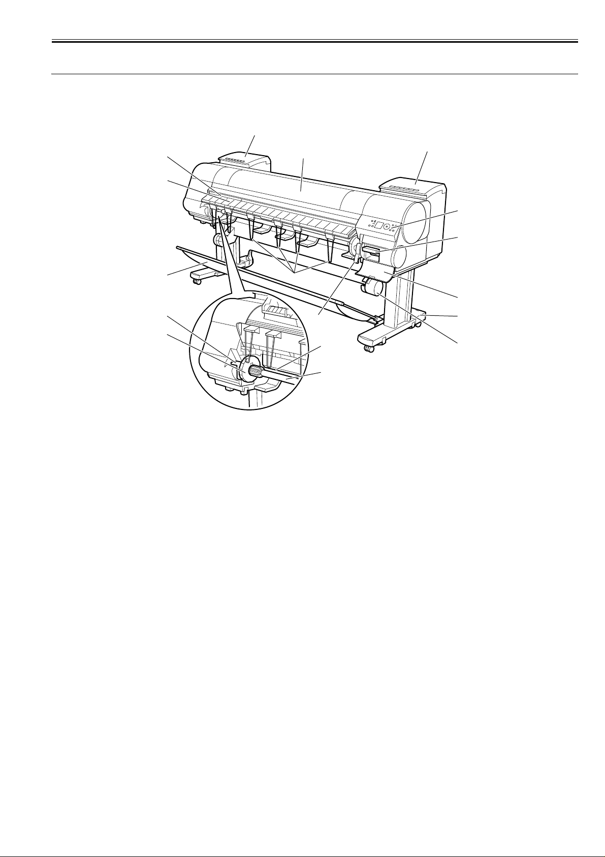
1.5 Names and Functions of Components
Chapter 1
1.5.1 Front
iPF9000 / iPF9000S / iPF9100
[3]
[4]
[5]
[6]
[7]
[2]
[10]
[1]
[11]
[9]
[8]
0012-6250
[2]
[16]
[15]
[14]
[13]
[12]
F-1-17
[1] Top Cover
Open this cover to install the Printhead, load paper, and remove any jammed paper from inside the printer as needed.
[2] Ink Tank Cover
Open this cover to replace an Ink Tank.
[3] Ejection Slot
All printed matter is ejected from this port.
[4] Ejection Guide
Guides printed documents as they are ejected. Open this guide when loading a roll.
[5] Output Stacker
A cloth tray that catches ejected documents.
[6] Roll Holder Slot
Slide the Roll Holder into this slot.
[7] Holder Stopper
Secure the roll on the Roll Holder with this part.
[8] Roll Holder
Load the roll on this holder.
[9] Paper Feed Slot
When loading a roll, insert the edge of the roll paper here.
[10] Ejection Support
Prevents printed documents from winding around the Roll Holder or Paper Feed Slot.
[11] Release Lever
Releases the Paper Retainer. Lift this lever toward the front of the printer when loading paper.
[12] Media Take-up Unit
Automatically winds up printed documents.
[13] Stand
A stand that holds the printer. Equipped with casters to facilitate moving the printer.
[14] Maintenance Cartridge Cover
Open this cover to replace the Maintenance Cartridge.
[15] Maintenance Cartridge
Ink used for maintenance purposes such as head cleaning is absorbed. (Replace the cartridge when it is full.)
[16] Operation Panel
Use this panel to operate the printer and check the printer status.
1-29
Page 42
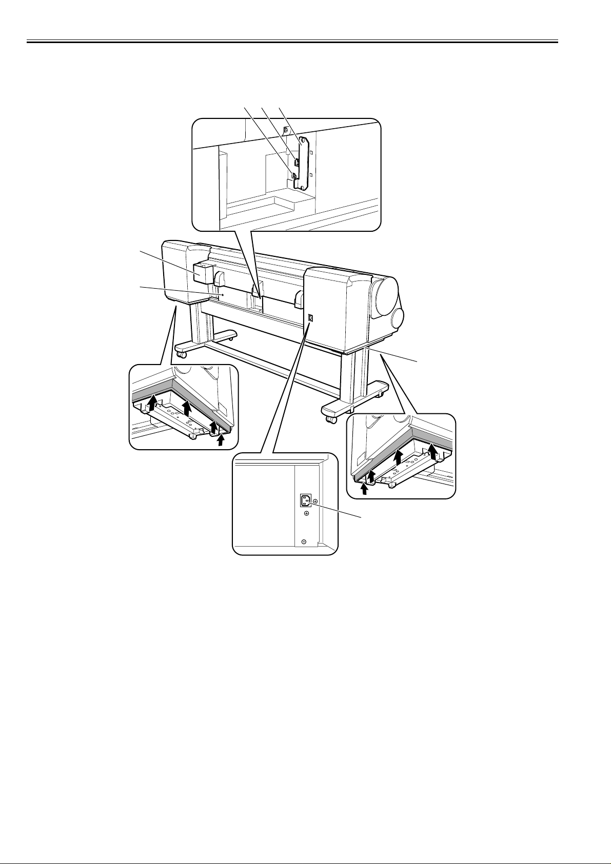
Chapter 1
1.5.2 Rear
iPF9000 / iPF9000S / iPF9100
[4]
[5]
[3]
[2]
0012-6260
[1]
[7]
[6]
F-1-18
[1] Expansion Board Slot
Install an IEEE 1394 (FireWire) expansion board, as desired.
[2] Ethernet Port
Connect an Ethernet cable to this port. The lamp is lit if the Ethernet cable is connected correctly and communication is possible between the computer and printer.
[3] USB Port
Connect a USB cable to this port. This port is compatible with USB 2.0 Hi-Speed mode.
[4] Accessory Pocket
Holds printer manuals, assembly tools, and other items.
[5] Media Take-up Unit Power Inlet
Connect the power cord of the Media Take-up Unit here.
[6] Power Supply Connector
Connect the power cord to this connector.
[7] Carrying handles
When carrying the printer, have six people hold it by these handles under both sides.
1-30
Page 43
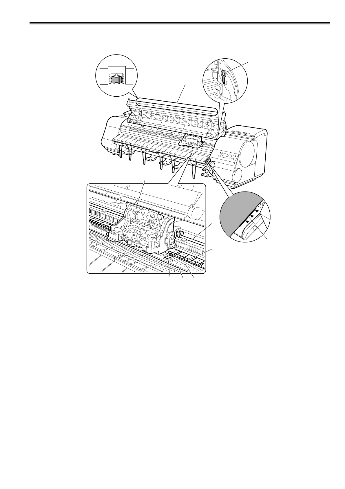
Chapter 1
1.5.3 Top Cover (Inside)
iPF9000 / iPF9000S / iPF9100
0017-8293
[9]
[1]
[2]
[7]
[6]
[5][4][3]
F-1-19
[1] Top Cover Roller
Prevents paper from rising when ejected.
[2] Carriage
Moves the Printhead. The carriage serves a key role in printing.
[3] Borderless Printing Ink Grooves
These grooves catch ink outside the edges of paper during borderless printing.
[4] Fixed Blade
The Cutter Unit passes through this blade to cut paper.
[5]Platen
The Printhead moves across the platen to print. The Vacuum holes on the platen hold paper in place.
[6] Pinch Roller
Important in supplying the paper. This retainer holds paper as it is fed.
[7] Carriage Shaft
The Carriage slides along this shaft.
[8] Paper Alignment Line
Align paper with this line when loading it.
[9] Cleaning Brush
When cleaning inside of the Top Cover, use this brush to sweep away paper dust on the Platen.
[8]
1-31
Page 44
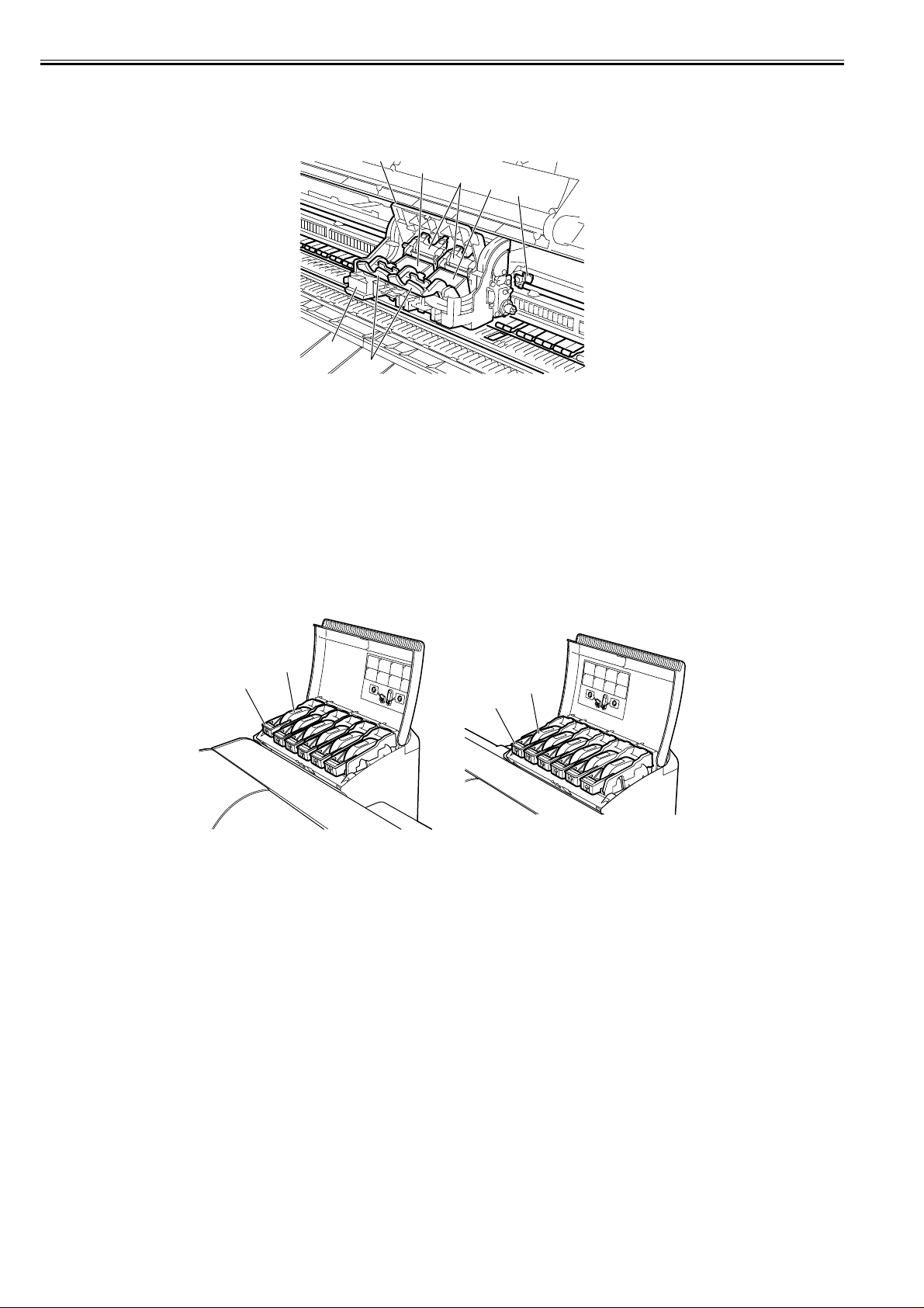
Chapter 1
1.5.4 Carriage
iPF9000 / iPF9000S / iPF9100
[3]
[2]
[1]
[2]
[6]
[4]
[5]
F-1-20
[1] Printhead Fixer Cover
Holds the Printhead in place.
[2] Printhead
Equipped with ink nozzles. Printheads serve a key role in printing.
[3] Carriage Cover
Protects the Carriage.
[4] Cutter Unit
A round-bladed cutter for automatic paper cutting. The cutter blade is retracted inside when not cutting.
[5] Printhead Fixer Lever
Locks the Printhead Fixer Cover.
[6] Shaft Cleaner
Prevents the Carriage Shaft from becoming dirty.
1.5.5 Ink Tank Cover (Inside)
iPF9000 / iPF9100
0012-6263
0017-8301
[1]
[2]
[1]
[2]
<Left> <Right>
F-1-21
[1] Ink Tank
Cartridges of ink in each color.
[2] Ink Tank Lock Lever
A lever that locks the Ink Tank in place and protects it. Lift and press down the lever when replacing an Ink Tank. To open it, lift the stopper of the lever until it
stops, and then push it down toward the front. To close it, push it down until it clicks into place.
1-32
Page 45

Chapter 1
1.5.6 Ink Tank Cover (Inside)
iPF9000S
[2]
[3]
[1]
[1]
[2]
0012-6273
<Left> <Right>
F-1-22
[1] Ink Tank
Cartridges of ink in each color.
[2] Ink Tank Lock Lever
A lever that locks the Ink Tank in place and protects it. Lift and press down the lever when replacing an Ink Tank. To open it, lift the stopper of the lever until it
stops, and then push it down toward the front. To close it, push it down until it clicks into place.
[3] Accessory Box
Holds CD-ROM included with the printer, reserved printhead, and other items.
1-33
Page 46
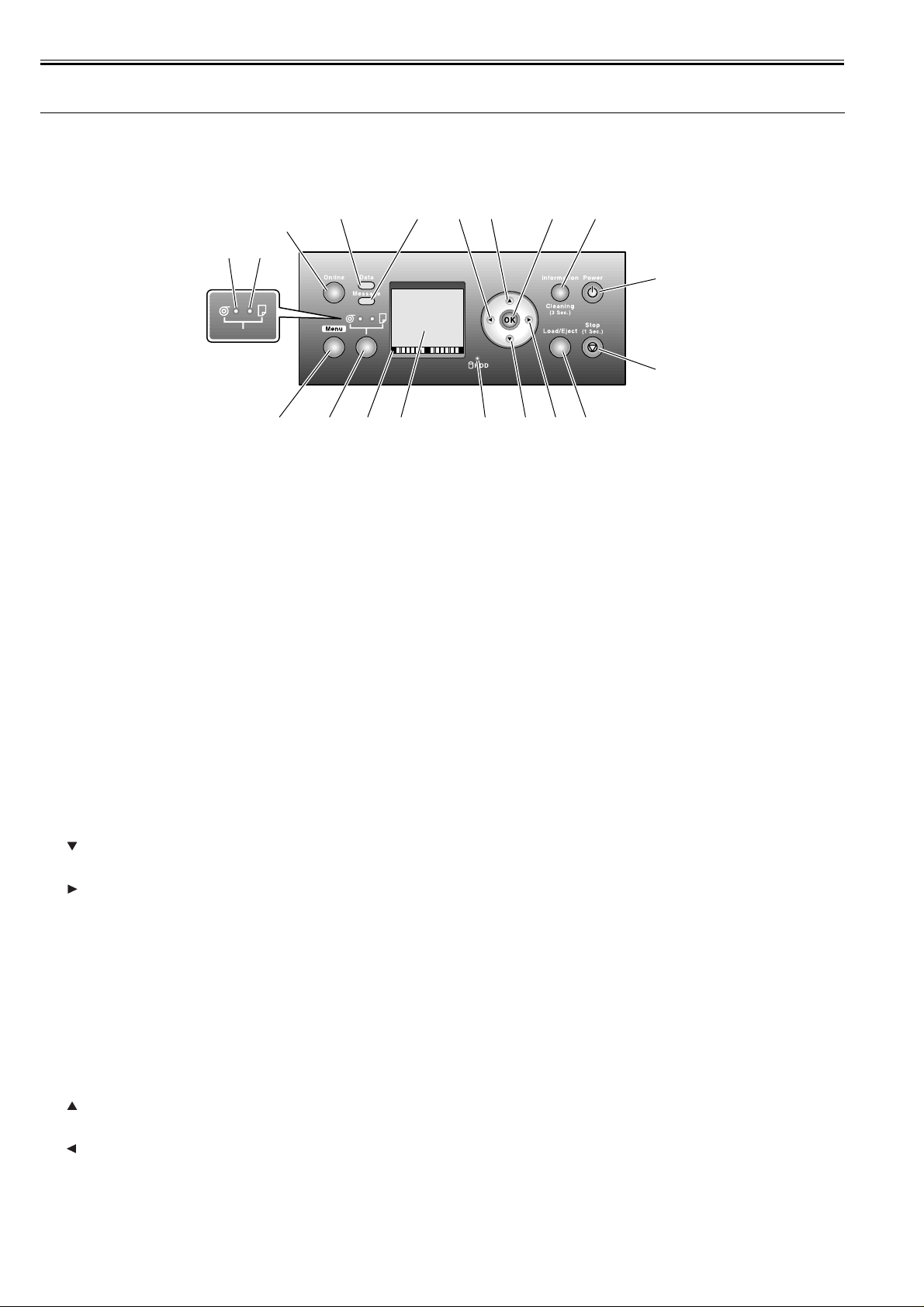
Chapter 1
1.6 Basic Operation
1.6.1 Operation Panel
iPF9000 / iPF9000S / iPF9100
0012-6277
This section explains the functions of the buttons and the meanings of the LEDs on the operation panel.
[3]
[4][5]
[11] [12] [13][10][6] [7] [8] [9]
F-1-23
[1] Message lamp
On: Indicates that a warning message is on display.
Blinking: Indicates that an error message is on display.
Off: The printer is normal or is turned off.
[2] Data lamp
Blinking: Indicates that a print job is being received or processed if the printer is printing, or that a print job has paused or firmware data is being if the printer is
not printing.
Off: No print job is available.
[3] Online button
Toggles the printer mode between online and offline.
On: Online mode.
Blinking: Emerging from sleep mode.
Off: Offline mode.
[4] Cut sheet lamp (green)
On: Either the paper tray or paper tray front loading port is selected as a paper source.
Off: Roll media are selected as a paper source.
[5] Roll media lamp (green)
On: Roll media are selected as a paper source.
Off: Either the paper tray or paper tray front loading port is selected as a paper source.
[6] Menu button
Displays the printer main menu.
[7] Paper source button
Selects a paper source. Each time this button is pressed, the paper source toggles between roll media (roll media source) and cut sheet (paper tray or paper tray
front loading port), with the paper source selector lamp illuminating.
[8] Color labels
Represent ink tank colors in association with the remaining ink levels shown in the display.
[9] Display
Displays the printer menu, status or messages.
[10] HDD lamp (Green)
On: Indicates the printer is accessing the hard disk.
Off: Indicates the printer is not accessing the hard disk.
[16][17][18][19][1][2]
[15]
[14]
[11] button
Press this button when the printer is in offline mode to manually feed roll media.
Press this button when the printer is in menu mode to view the next item or setting.
[12] button
Press this button when the printer is in menu mode to view the menu at the lower level.
If [NEXT -->] on display, the guidance screen can be moved forward.
[13] Load/Eject button
Guidance offers a visual clue to loading (replacing)/removing paper. Press this button when no paper is loaded to view instructions on how to load (replace) paper
in the display; press the button when paper is loaded to view instructions on how to remove the paper.
[14] Stop button
Press for longer than 1 second to cancel the job or ink drying process in progress.
If cut sheet loading guidance or the like is on display, hold this button for longer than 1 second to stop the guidance.
[15] Power button
Turns the printer on and off.
[16] Information button
Displays the printer submenu. Each time this button is pressed, information about the inks and paper is displayed.
Hold this button depressed for 3 seconds to execute printhead cleaning ([Head Cleaning A]).
[17] OK button
Press to set or set or execute a menu choice when the printer is in menu mode.
Press this button in any other situation to transition to the next screen as directed by a message appearing in the display.
[18] button
Press this button when the printer is in offline mode to manually feed roll media in the direction opposite to that of ejection.
Press this button when the printer is in menu mode to view the last item or setting.
[19] button
Press this button when the printer is in menu mode to view the menu at the upper level.
The button is also used from one position to the next when entering a numeric value.
If [<-- STOP] is on display, the guidance screen can be paused.
If [<-- BACK] on display, the guidance screen can be moved backward.
1-34
Page 47

Chapter 1
1.6.2 Main Menu
iPF9000
0012-6282
The printer has a Main Menu which provides the user with access to various adjusting and configuring features, for example: adjusting print position; performing
cleaning or other maintenance features; auto-cutting, ink drying time and other print settings; message language and other parameter settings.
1. Main menu operations
a) How to enter the Main menu
To enter the Main menu, press the [Menu] button on the operation panel.
b) How to exit the Main menu
To exit the Main menu, press the [Online] button.
c) Buttons used with the Main menu
- Selecting menus and parameters: [ ] or [ ] button
- Going to the next lower-level menu: [ ] button
- Going to the next higher-level menu: [ ] button
- Determining a selected menu or parameter: [OK] button
1-35
Page 48

Chapter 1
2. Main Menu
The structure of the main menu is as follows.Values at right indicated by an asterisk "*" are the defaults.
First Level Second Level Third Level Fourth Level Fifth Level
[Paper Cut](*1) [No]
[Yes]
[Rep. Ink Tank] [No]
[Yes]
[Head Cleaning] [Head Cleaning A]
[Head Cleaning B]
[Auto Feed] [No]
[Yes]
[Take-up Reel] [Disable]*
[Enable]
[Media Menu] [Roll Media Type](*1) [Plain Paper](*5)
[Plain Paper HQ](*5)
[Plain Paper HG](*5)
[Recycled Coated](*5)
[Coated Paper](*5)
[HW Coated](*5)
[Ex HW Coated](*5)
[Premium MatteP](*5)
[Glossy Photo](*5)
[Glossy Photo2](*5)
[Semi-Gl Photo](*5)
[Semi-Gl Photo2](*5)
[HW Glossy Photo](*5)
[HW SemiGl Photo](*5)
[Syn. Paper](*5)
[Adh. Syn. Paper](*5)
[Backlit Film](*5)
[Backprint Film](*5)
[Flame-Res.Cloth](*5)
[Fabric Banner](*5)
[ThinFab.Banner](*5)
[Proofing Paper](*5)
[News Proof 1](*5)
[News Proof 2](*5)
[News Proof 3](*5)
[FineArt Photo](*5)
[FneArt HW Photo](*5)
1-36
Page 49

First Level Second Level Third Level Fourth Level Fifth Level
[Media Menu] [Roll Media Type](*1) [FineArt Txtr](*5)
[FineArt Wtrclr](*5)
[FineArtBlockP](*5)
[Canvas Matte2](*5)
[Canvas Semi-Gl](*5)
[JPN Paper Washi](*5)
[Colored Coated](*5)
[CAD Trace Paper](*5)
[CAD Matte Film](*5)
[CAD Clear Film](*5)
[Special #] (Here, the number is
1-5) (*5)
[Chk Remain.Roll] [Off]*
[On]
[Roll Length Set](*2) [### m](*9)
[### feet](*9)
[Cut Sheet Type] [Plain Paper](*5)
[Plain Paper HQ](*5)
[Plain Paper HG](*5)
[Recycled Coated](*5)
[Coated Paper](*5)
[HW Coated](*5)
[Ex HW Coated](*5)
[Premium MatteP](*5)
[Glossy Photo](*5)
[Glossy Photo2](*5)
[Semi-Gl Photo](*5)
[Semi-Gl Photo2](*5)
[HW Glossy Photo](*5)
[HW SemiGl Photo](*5)
[Syn. Paper](*5)
[Adh. Syn. Paper](*5)
[Backlit Film](*5)
[Backprint Film](*5)
[Flame-Res.Cloth](*5)
[Fabric Banner](*5)
[ThinFab.Banner](*5)
Chapter 1
1-37
Page 50

Chapter 1
First Level Second Level Third Level Fourth Level Fifth Level
[Media Menu] [Cut Sheet Type] [Proofing Paper](*5)
[News Proof 1](*5)
[News Proof 2](*5)
[News Proof 3](*5)
[FineArt Photo](*5)
[FneArt HW Photo](*5)
[FineArt Txtr](*5)
[FineArt Wtrclr](*5)
[FineArtBlockP](*5)
[Canvas Matte2](*5)
[Canvas Semi-Gl](*5)
[JPN Paper Washi](*5)
[Colored Coated](*5)
[CAD Trace Paper](*5)
[CAD Matte Film](*5)
[CAD Clear Film](*5)
[Special #] (Here, the number is
1-5) (*5)
[Paper Details] (The paper type is displayed
here.)(*5)
[Roll DryingTime] [Off]
[Scan Wait Time] [Off]
[Feed Priority] [Automatic]
[Adjust Length] -0.70% - 0.00%* - 0.70%
[Head Height] [Automatic]
[30 sec.]
[1 min.]
[3 min.]
[5 min.]
[10 min.]
[30 min.]
[60 min.]
[1 sec.]
[3 sec.]
[5 sec.]
[7 sec.]
[9 sec.]
[Band Joint]
[Print Length]
[Lowest]
[Low]
[Standard]
[High]
[Highest]
1-38
Page 51

First Level Second Level Third Level Fourth Level Fifth Level
[Paper Details] (The paper type is displayed
[Job Management] [Job Queue Ope.] [Job List] (Choose a print job) [Priority]
here.)(*5)
[Com. BOX Ope.] [Job List] (Choose a print job) [Print]
[Psnl. BOX Ope.] [Folder List]
[Skew Check Lv.] [Standard]
[Off]
[Loose]
[VacuumStrngth] [Automatic]
[Strongest]
[Strong]
[Standard]
[Weak]
[Weakest]
[Width Detection] [Off]
[On]
[NearEnd RollMrgn] [5mm]
[20mm]
[Cut Speed] [Standard]
[Fast]
[Slow]
[Trim Edge First] [Automatic]
[Off]
[On]
[Cutting Mode] [Automatic]
[Eject]
[Manual]
[Bordless Margin] [Automatic]
[Fixed]
[CutDustReduct.] [Off]
[On]
[NearEnd Sht Mrgn] [5mm]
[20mm]
[Return Defaults] [No]
[Yes]
(Enter a password if one has
been set.)
[Job List]
(Choose a print job)
[Print Job List] [No]
[Delete]
[Delete]
[Print]
[Delete]
[Yes]
Chapter 1
1-39
Page 52

Chapter 1
First Level Second Level Third Level Fourth Level Fifth Level
[Adjust Printer] [Auto Head Adj.] [Standard Adj.] [No]
[Advanced Adj.] [No]
[Auto Print] [Off]
[Manual Head Adj] [No]
[Yes]
[Auto Band Adj.] [Standard Adj.] [No]
[Advanced Adj.] [No]
[Manual Band Adj] [No]
[Yes]
[Adjust Length] [No]
[Yes]
[Interface Setup] [EOP Timer] [10 sec.]
[30 sec.]
[1 min.]
[2 min.]
[5 min.]
[10 min.]*
[30 min.]
[60 min.]
[TCP/IP] [TCP/IP] [On]
[IP Mode] [Automatic]
[Protocol](*4) [DHCP] [On]
[IP Setting] [IP Address] 0.0.0.0 - 255.255.255.255
[NetWare] [NetWare] [On]
[Frame Type](*6) [Auto Detect]
[Print Service](*6) [BinderyPServer]
[Yes]
[Yes]
[On]*
[Yes]
[Yes]
[Manual]*
[Off]*
[BOOTP] [On]
[Off]*
[RARP] [On]
[Off]*
[Subnet Mask] 0.0.0.0 - 255.255.255.255
[Default G/W] 0.0.0.0 - 255.255.255.255
[Off]*
[Ethernet 2]
[Ethernet 802.2]*
[Ethernet 802.3]
[Ethernet SNAP]
[RPrinter]
[NDSPServer]*
[NPrinter]
1-40
Page 53

First Level Second Level Third Level Fourth Level Fifth Level
[Interface Setup] [AppleTalk] [On]
[Off]*
[Ethernet Driver] [Auto Detect] [On]*
[Off]
[Comm.Mode](*7) [Half Duplex]*
[Full Duplex]
[Ethernet Type](*7) [10 Base-T]*
[100 Base-TX]
[Spanning Tree] [Not Use]*
[Use]
[MAC Address] 000085XXXXXX
[Init. Settings] [No]*
[Yes]
[Maintenance] [Maint. cart.] [No]
[Yes]
[Replace P.head] [Printhead L] [No]
[Yes]
[Printhead R] [No]
[Yes]
[L & R Printheads] [No]
[Yes]
[Repl. S. Cleaner] [No]
[Yes]
[Change Cutter] [No]
[Yes]
[Move Printer] [Level 1]
[Level 2]
[Level 3]
[System Setup] [Warning] [Buzzer] [Off]
[On]*
[Detect Mismatch] [Off]
[On]*
[Skip Take-Up Err] [Off]*
[On]
[Keep Media Size] [Off]*
[On]
[Paper Size Basis] [Sht Selection 1] [ISO A3+]*
[ANSI B Super]
[Sht Selection 2] [ISO B1]*
[ANSI F]
Chapter 1
1-41
Page 54

Chapter 1
First Level Second Level Third Level Fourth Level Fifth Level
[System Setup] [Noz. Check Freq.] [Off]
[Sleep Timer] [5 min.]*
[Length Unit] [meter]*
[Time Zone] [0: London (GMT)]
[Date Format] [yyyy/mm/dd]*
[Date & Time] [Dat e] [yyyy/mm/dd](*8)
[1 page]
[10 pages]
[Automatic]*
[10 min.]
[15 min.]
[20 min.]
[30 min.]
[40 min.]
[50 min.]
[60 min.]
[feet/inch]
[+1: Paris, Rome]
[+2: Athens, Cairo]
[+3: Moscow]
[+4: Eerenan, Baku]
[+5: Islamabad]
[+6: Dacca]
[+7: Bangkok]
[+8: Hong Kong]
[+9: Tokyo, Seoul]
[+10: Canberra]
[+11: NewCaledonia]
[+12: Wellington]
[-12: Eniwetok]
[-11: Midway is]
[-10: Hawaii (AHST)]
[-9: Alaska (AKST)]
[-8: Oregon (PST)]
[-7: Arizona (MST)]
[-6: Texas (CST)]
[-5: NewYork (EST)]
[-4: Santiago]
[-3: Buenos Aires]
[-2: ]
[-1: Cape Verde]
[dd/mm/yyyy]
[mm/dd/yyyy]
[Time] [hh:mm]
1-42
Page 55

Chapter 1
First Level Second Level Third Level Fourth Level Fifth Level
[System Setup] Language [Japanese]*
[Francais]
[Italiano]
[Deutsch]
[Espanol]
[Chinese]
[Korea]
[English]
[Contrast Adj.] -4,-3,-2,-1,0*,+1,+2,+3,+4
[Reset PaprSetngs] [No]
[Yes]
[Erase HDD Data] [NULL] [No]
[Yes]
[Random Data 1x] [No]
[Yes]
[Random Data 3x] [No]
[Yes]
[Test Print] [Status Print] [No]
[Yes]
[Media Details] [No]
[Yes]
[Print Job Log] [No]
[Yes]
[Menu Map] [No]
[Yes]
[Nozzle Check] [No]
[Yes]
[Information] [System Info]
[Error Log] [########-####]
[Job Log] (Choose from information
[HDD Information] [HDDSpace:]
about the latest three print
jobs.)
[Document Name]
[User Name]
[Page Count]
[Job Status]
[Print Start Time]
[Print End Time]
[Print Time]
[Print Size]
[Media Type]
[Interface]
[Ink Consumed]
*1: Available only if a roll is loaded.
*2: Available only if Chk Remain.Roll is On.
*3: Available only if Feed Priority is Print Length.
*4: Available only if IP Mode is Automatic.
*5: For information on the types of paper the printer supports, refer to the Media Guide. The paper type setting in the printer driver and related software (as well as
on the Control Panel) is updated when you install the printer driver from the User Software CD-ROM or if you change paper information by using the Media Configuration Tool.
*6: Available only if NetWare is On.
*7: Available only if Auto Detect is Off.
*8: Follows the setting in Date Format.
*9: Follows the setting in Length Unit.
1-43
Page 56

Chapter 1
3. Main menu during printing
The structure of the main menu during printing is as follows.
First Level Second Level Third Level Fourth Level Fifth Level
[Menu Durng Prtng] [Head Cleaning] [Head Cleaning A]
[Fine Band Adj.] -3 - 0 - 3
[Information] [System Info]
[Job Management] [Job Queue Ope.] [Job List] (Choose a print job) [Priority]
[Com. BOX Ope.] [Job List] (Choose a print job) [Print]
[Psnl. BOX Ope.] [Folder List]
[Head Cleaning B]
[Error Log] [########-####]
[Job Log] (Choose from information
[HDD Information]
[Print Job List] [No]
(Enter a password if one has
been set.)
about the latest three print
jobs.)
[Yes]
[Job List]
(Choose a print job)
[Print Job List] [No]
[Document Name]
[User Name]
[Page Count]
[Job Status]
[Print Start Time]
[Print End Time]
[Print Time]
[Print Size]
[Media Type]
[Interface]
[Ink Consumed]
[Delete]
[Delete]
[Print]
[Delete]
[Yes]
1-44
Page 57

4. Main Menu Settings
Main menu items are described in the following tables.
Setting Item Description, Instructions
[Paper Cut] This command is available only if a roll is loaded.
[Rep. Ink Tank] When replacing the Ink Tank, choose Yes and follow the instructions on the screen.
[Head Cleaning] Specify Printhead cleaning options.
[Auto Feed] This command is available only if Take-up Reel is set to Enable. Choose Yes to advance roll paper
[Take-up Reel] Choose Enable to use the Media Take-up Unit.
[Media Menu] Specify the type and size of paper.
[Paper Details] Specify detailed paper-related settings, including the ink drying time and borderless printing options.
[Job Management] Manage print jobs on the printer's hard disk.
[Adjust Printer] Adjust the Printhead alignment or amount of feed by printing a test pattern.
[Interface Setup] Configure the EOP timer and network settings.
[Maintenance] Access maintenance settings when replacing the Printhead or preparing to move the printer.
[System Setup] Specify the printer system settings, including the date format and display language.
[Test Print] Choose Status Print to print information about the printer.
[Information] Displays information about the printer and record of print jobs.
[Media Menu]
Chapter 1
Choose Yes to cut the roll at the current position. However, if paper cannot be advanced to the cut position,
it will not be cut. In this case, manually advance the roll before cutting it.
Choose Head Cleaning A if printing is faint, oddly colored, or contains foreign substances.
Choose Head Cleaning B if no ink is printed at all, or if printing is not improved by Head Cleaning A.
automatically on the Rewind Spool, up to the fastening position.
Choose Media Details to print the paper settings as specified in Paper Details.
Choose Print Job Log to print a record of print jobs, including the paper type and size, amount of ink used,
and so on. (Information on ink consumption is general, not specific in nature.)
Choose Menu Map to print a list of the main menu options.
Choose Nozzle Check to print a test pattern for checking the nozzles.
Setting Item Description, Instructions
[Cut Sheet Type] Choose the type of sheets.
[Roll Media Type] Choose the type of roll.
[Chk Remain.Roll] Choose On to print a barcode at the end of a roll before you remove it. The printed barcode can be used in
[Roll Length Set] Displayed if Chk Remain.Roll is On.
managing the amount of roll paper left. ChooseOff if you prefer not to print the barcode.
If a barcode is not printed on rolls, specify the roll length. The roll length is displayed in meters or feet,
depending on the setting in Length Unit.
1-45
Page 58

Chapter 1
[Paper Details]
(The paper type is displayed here.) [Roll DryingTime] Specify the time to wait for the ink to dry for each sheet.
[Job Management]
Setting Item Description, Instructions
[Scan Wait Time] Specify the time to wait for the ink to dry between each scan in bidirectional printing,
[Feed Priority] Specify exact paper feeding, if desired. Normally, select Automatic. Choose Print
[Adjust Length] Displayed if Feed Priority is Print Length.
[Head Height] Adjust the Printhead height.
[Skew Check Lv.] If you print on Japanese paper (washi) or other handmade paper that has an irr egular
[VacuumStrngth] Specify the level of suction that holds paper against the Platen.
[Width Detection] Make this setting when the print size is different from the media size, for example,
[NearEnd RollMrgn] Specify the minimum margin at the leading edge of roll paper to ensure better
[Cut Speed] Choose the cutting speed. If you use adhesive paper, choosing Slow helps prevent
[Trim Edge First] If a roll is loaded, the end of the paper will be cut.
[Cutting Mode] Specify whether or not to cut with the standard round-bladed cutter.
[Bordless Margin] Adjust the margin during borderless printing.
[CutDustReduct.] Choose On to reduce the amount of debris generated when cutting film and similar
[NearEnd Sht Mrgn] Specify a margin at the leading edge of sheets to ensure better printing quality at the
[Return Defaults] Choose Yes to restore Paper Details to the factory default values.
in consideration of how quickly the ink dries. Note that printing will take longer if
you specify a wait time.
Length if you prefer to feed the paper an exact amount. However, note that choosing
Print Length may result in slight banding in the direction of Carriage scanning.
Adjustment relative to the amount of stretching or shrinkage of the current paper.
Enter either the adjustment results from Print Pattern or the discrepancy that you
measured (as a percentage).
For paper that tends to stretch, increase the feed amount by setting the adjustment
value toward +. For paper that tends to shrink, decrease the feed amount by setting
the adjustment value toward -.
width, choose Loose for a higher skew detection threshold, or choose Off to disable
skew detection. However, if paper is loaded askew when detection is Off, note that
paper jams or Platen soiling may occur.
when you want to make a print within a frame.
When you select [OFF], the paper width is not detected.
printing quality at the leading edge.
Note that if you choose 5mm, it may lower the printing quality at the leading edge
and affect feeding accuracy. The printed surface may be scratched, and ink may
adhere to the leading edge. It may also cause the Platen to become soiled.
adhesive from sticking to the cutter and keeps the cutter sharp.
Choose Automatic to have the roll cut automatically after printing. If you choose
Manual, the paper will not be cut after printing. Instead, a line will be printed at the
cut position.
Choose Eject if you prefer not to have documents dropped immediately after
printing, as when waiting for ink to dry.
Choose Automatic to have the printer automatically detect the paper width and
configure the margin settings for borderless printing. If margins are mistakenly
created when Automatic is selected, choose Fixed. In this case, the paper width is
not detected automatically, and the document is printed without borders, using the
margin settings required by the printer.
media by printing a line at the cut position. This option reduces the amount of debris
given off after cutting. It also helps prevent adhesive from sticking to the cutter and
keeps the cutter sharp if you use adhesive paper.
leading edge.
Note that if you choose 5mm, it may lower the printing quality at the leading edge
and affect feeding accuracy. The printed surface may be scratched, and ink may
adhere to the leading edge.
1-46
Setting Item Description, Instructions
[Job Queue Ope.] [Job List] (Choose a print job) ]Delete] Print the job first after the
[Priority] Delete the current job or
[Com. BOX Ope.] [Job List] (Choose a print job) [Print] Print jobs in the Common Box.
[Delete] Delete jobs in the Common
[Print Job List] Print a list of jobs in the
[Psnl. BOX Ope.] [Folder List] (Enter a password if one has
been set.)
[Job List]-[Print] Print jobs in Personal Boxes.
[Job List]-[Delete] Delete jobs in Personal Boxes.
[Print Job List] Print a list of jobs in Personal
current print job is finished
printing.
queued jobs.
Box.
Common Box.
Boxes.
Page 59

[Adjust Printer]
[Auto Head Adj.] [Standard Adj.] Choose Yes to have the printer print and read a test pattern for the automatic
[Manual Head Adj] Choose Yes to print a test pattern for adjustment of Printhead alignment relative to
[Auto Band Adj.] [Standard Adj.] Choose Yes to have the printer print and read a band adjustment test pattern for
[Manual Band Adj] Choose Yes to print a test pattern for adjusting the feed amount based on the paper
[Adjust Length] Choose Yes to print a test pattern for adjustment relative to paper stretching or
[Interface Setup]
[EOP Timer] Specify the timeout period before cancellation of print jobs that cannot be
[TCP/IP] [TCP/IP] Specify the TCP/IP protocol settings. To apply your changes, choose Register
[NetWare] [NetWare] Specify the NetWare protocol. To apply your changes, choose Register Setting.
[AppleTalk] Specify whether to use the AppleTalk protocol. To apply your changes, choose
[Ethernet Driver] [Auto Detect] Specify the communication method. To apply your changes, choose Register
[Init. Settings]
[Maintenance]
Chapter 1
Setting Item Description, Instructions
adjustment of Printhead alignment relative to the printing direction.
[Advanced Adj.] Choose Yes to have the printer print and read a test pattern for the automatic
[Auto Print] Choose On to have the printer automatically execute the Advanced Adj. operations
[Advanced Adj.] Choose this option when using paper other than genuine Canon paper, or paper for
Setting Item Description, Instructions
[IP Mode] Choose whether the printer IP address is configured automatically or a static IP
[Protocol] [DHCP] Specify the protocol used to configure the IP address autom atic a lly .
[BOOTP]
[RARP]
[IP Setting] [IP Address] Specify the printer network information when using a static IP address.
[Subnet Mask]
[Default G/W]
[Frame Type] Specify the frame type to use.
[Print Service] Choose the print service.
[Comm.Mode] Choose the LAN communication method.
[Ethernet Type] Choose the LAN transfer rate.
[Spanning Tree] Choose whether spanning-tree packets are supported over the LAN.
[MAC Address] Displays the MAC address.
adjustment of Printhead alignment relative to the nozzle and printing direction.
after you replace the Printhead.
the printing direction. Enter the adjustment value manually based on the resulting
pattern.
automatic adjustment of the feed amount.
purposes other than checking output.
Choose Yes to have the printer print and read a band adjustment test pattern for
automatic adjustment of the feed amount. Note that this function takes more time
and requires more ink than Standard Adj.
type.
shrinkage, after which you can enter the amount of adjustment.
received by the printer.
Setting.
address is entered manually.
Enter the IP address assigned to the printer, as well as the network subnet mask
and default gateway.
Register Setting.
Setting.
Choose On for automatic configuration of the LAN communication protocol.
Choose Off to use settings values of Comm.Mode and Ethernet Type.
Execute? is displayed if you press the button. Choose OK to restore the
network settings to the default values.
Setting Item Description, Instructions
[Maint. cart.] When replacing the Maintenance Cartridge, choose Yes and follow the instructions on the screen.
[Replace P.head] Not displayed during a warning message that the remaining Maintenance Cartridge capacity is low.
[Repl. S. Cleaner] When replacing the Shaft Cleaner, choose Yes and follow the instructions on the screen.
[Change Cutter] When replacing the Cutter Unit, choose Yes and follow the instructions on the screen.
[Move Printer] When transferring the printer to another location, choose the level of transfer and follow the instructions on
When replacing the Printhead, choose Yes and follow the instructions on the screen.
You can also reset the cut counter after the Cutter Unit is replaced.
the screen.
1-47
Page 60
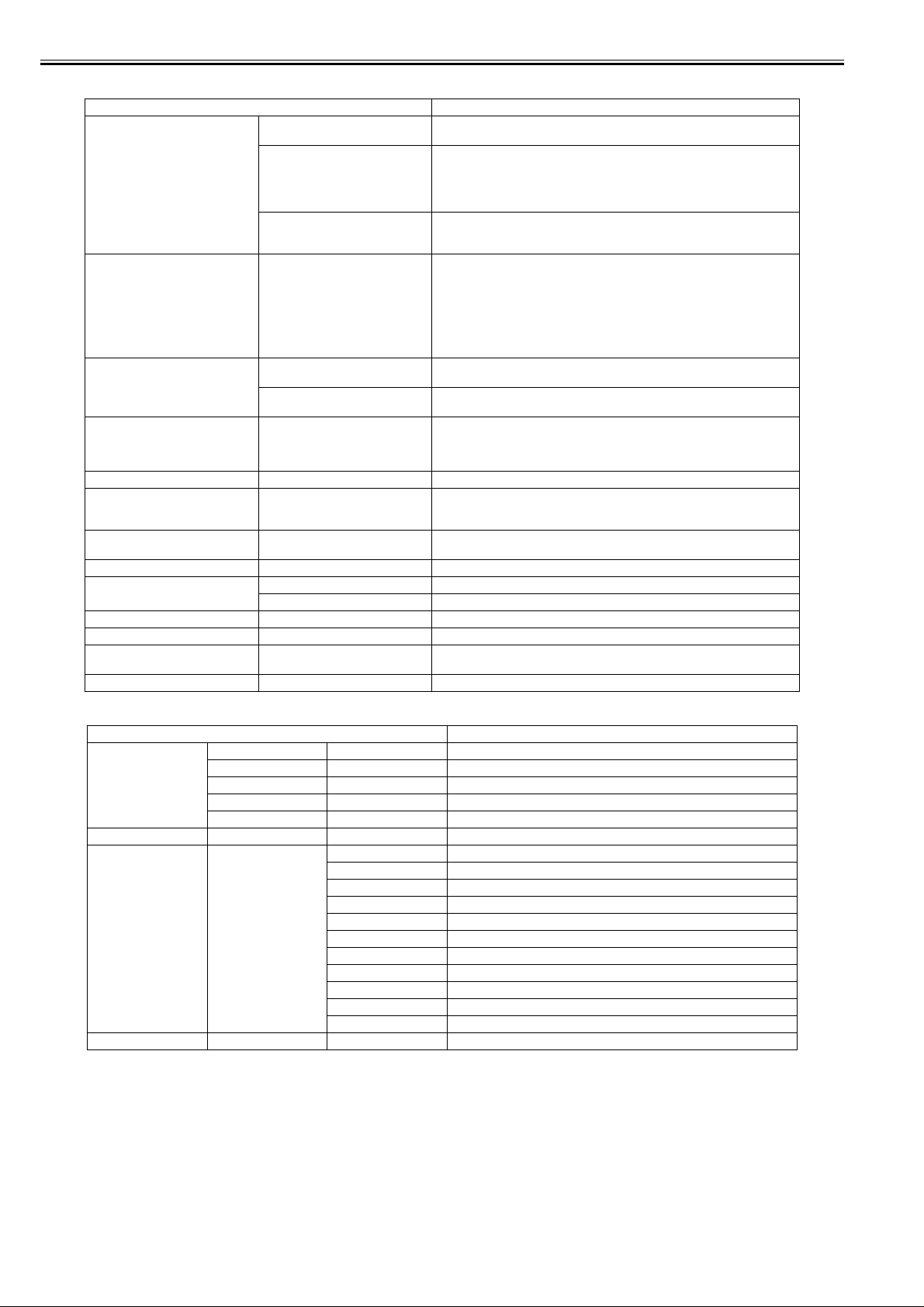
Chapter 1
[System Setup]
[Warning] [Buzzer] Set the buzzer. Choose On for the buzzer to sound once for warnings and three times
[Keep Media Size] Choose On to use the paper size setting as the basis for printing instead of other
[Paper Size Basis] [Sht Selection 1] If sheet size detection is activated, choose whether ISO A3+ or ANSI B Super is
[Noz. Check Freq.] Specify the timing for automatic checks of nozzle clogging. Choose 1 page to check
[Sleep Timer] Specify the period before the printer enters Sleep mode.
[Length Unit] Choose the unit of measurement when roll length is displayed. You can switch the
[Time Zone] Specify the time zone. Time zone options indicate a main city in this time zone and
[Date Format] Specify the date format.
[Date & Time] [Date] Set the current date.
[Language] Specify the language used on the Display Screen.
[Contrast Adj.] Adjust the Display Screen contrast level.
[Reset PaprSetngs] Restores settings that you have changed with Media Configuration Tool to the
[Erase HDD Data] Erase all data on the hard disk.
[Information]
Setting Item Description, Instructions
for errors.
[Detect Mismatch] Choose On to continue with printing even if the paper type and size settings are
[Skip Take-Up Err] Choose On to continue with printing even if an error occurs with the Media Take-up
[Sht Selection 2] If sheet size detection is activated, choose whether ISO B1 or ANSI F is applied
[Time] Set the current time.
different in the printer menu and printer driver. Choose Off to have the printer pause
before printing if the paper type specified in the printer menu does not match the
paper type in the printer driver. In this case, you can continue printing by pressing
the Online button.
Unit. Choose Off to have the printer pause before printing if a rewinding error
occurs.
settings. The margin setting of the printer menu will be used instead of the margin
setting of the printer driver if the latter is smaller, which may prevent text or images
in the margin from being printed.
Choose Off to use the printer driver settings instead. Even if the margin setting of
the printer driver is smaller than that of the printer driver, text or images will not be
cut off. However, this requires longer paper because the actual margin will be equal
to the margin setting of the printer driver plus the margin setting of the printer menu.
applied when an intermediate size is detected.
when an intermediate size is detected.
once per printed page. Choose 10 pages to check once per ten printed pages. Choose
Automatic to have the printer automatically adjust the timing for checks based on
the frequency of nozzle use.
unit displayed for Roll Length Set and the remaining paper amount displayed in the
submenu.
the difference from Greenwich Mean Time.
factory default values.
Setting Item Description, Instruc tion s
[System Info] [Firmware] Displays the version of the printer and firmware.
[Boot] Displays the version of the boot ROM.
[MIT] Displays the version of the MIT database format.
[s/n:] Displays the printer's serial number.
[IP] Displays the printer's IP address.
[Error Log] [########-####] Displays the most recent error messages (up to two).
[Job Log] (Choose from information
[HDD Information] [HDDSpace:] Displays the space available on the printer's hard disk.
about the latest three print
jobs.)
[Document Name] Displays the document name in the last print job.
[User Name] Displays the name of the user who sent the print job.
[Page Count] Displays the number of pages in the print job.
[Job Status] Displays the results of the print job processed.
[Print Start Time] Displays the time when the print job was started.
[Print End Time] Displays the time when the print job was finished.
[Print Time] Displays the time required to print the job.
[Print Size] Displays the paper size in the print job.
[Media Type] Displays the paper type in the print job.
[Interface] Displays the interface used for the print job.
[Ink Consumed] Displays the ink consumption.
1-48
Page 61

5. Main Menu Settings (During Printing)
Main menu items during printing are described in the following tables.
Setting Item Description, Instructions
[Head Cleaning] Specify Printhead cleaning options.
[Fine Band Adj.] Fine-tune the feed amount manually.
[Information] Displays information about the printer and record of print jobs.
[Job Mgmt Menu] Perform operations related to print jobs on the printer's hard disk.
Choose Head Cleaning A if printing is faint, oddly colored, or contains foreign substances.
Choose Head Cleaning B if no ink is printed at all, or if printing is not improved by Head Cleaning A.
[Information]
Setting Item Description, Instructions
[System Info] [Firm. Ver. ] Displays the version of the printer and firmware.
[Boot] Displays the version of the boot ROM.
[MIT] Displays the version of the MIT database format.
[IP] Displays the printer's IP address.
[Ext.Interface] Displays the name of interfaces compatible with the expansion slot.
[s/n] Displays the printer's serial number.
[Error Log] [########-####] Displays the most recent error messages (up to two).
[Job Log] (Choose from information
[HDD Information] [HDDSpace:] Displays the space available on the printer's hard disk.
about the latest three print
jobs.)
[Document Name] Displays the document name in the last print job.
[User Name] Displays the name of the user who sent the print job.
[Page Count] Displays the number of pages in the print job.
[Job Status] Displays the results of the print job processed.
[Print Start Time] Displays the time when the print job was started.
[Print End Time] Displays the time when the print job was finished.
[Print Time] Displays the time required to print the job.
[Print Size] Displays the paper size in the print job.
[Media Type] Displays the paper type in the print job.
[Interface] Displays the interface used for the print job.
[Ink Consumed] Displays the ink consumption.
[Job Management]
Chapter 1
Setting Item Description, Instructions
[Job Queue Ope.] [Job List] (Choose a print job) [Delete] Delete the current job or
[Priority] Print the job first after the
[Com. BOX Ope.] [Job List] (Choose a print job) [Print] Print jobs in the Common Box.
[Delete] Delete jobs in the Common
[Print Job List] Print a list of jobs in the
[Psnl. BOX Ope.] [Folder List] (Enter a password if one has
been set.)
[Job List]-[Print] Print jobs in Personal Boxes.
[Job List]-[Delete] Delete jobs in Personal Boxes.
[Print Job List] Print a list of jobs in Personal
queued jobs.
current print job is finished
printing.
Box.
Common Box.
Boxes.
1-49
Page 62

Chapter 1
1.6.3 Main Menu
iPF9000S / iPF9100
0017-8306
The printer has a Main menu which includes a menu related to maintenance such as adjustment of ink ejection position of each nozzle and head cleaning, a menu
related to printing settings such as auto cutting and ink drying time, and a menu related to parameters such as a message language.
1. Main menu operations
a) How to enter the Main menu
To enter the Main menu, press the [Menu] button on the operation panel.
b) How to exit the Main menu
To exit the Main menu, press the [Online] button.
c) Buttons used with the Main menu
- Selecting menus and parameters: [ ] or [ ] button
- Going to the next lower-level menu: [ ] button
- Going to the next higher-level menu: [ ] button
- Determining a selected menu or parameter: [OK] button
1-50
Page 63

2. Main Menu
The structure of the main menu is as follows.
First Level Second Level Third Level Fourth Level Fifth Level
[Paper Cut](*1) [No]*
[Yes]
[Rep. Ink Tank] [No]*
[Yes]
[Head Cleaning] [Head Cleaning A]*
[Head Cleaning B]
[Auto Feed](*13) [No]*
[Yes]
[Take-up Reel](*10) [Disable]*
[Enable]
[Media Menu] [Cut Sheet Type] [Plain Paper](*5)
Chapter 1
T-1-7
[Plain Paper HQ](*5)
[Plain Paper HG](*5)
[Recycled Coated](*5)
[Coated Paper](*5)
[HW Coated](*5)
[Ex HW Coated](*5)
[Premium MatteP](*5)
[Glossy Photo](*5)
[Semi-Gl Photo](*5)
[HW SemiGl Photo](*5)
[HW SemiGl Photo2](*5)
[Poster Semi-Gl](*5)
[Syn. Paper](*5)
[Adh. Syn. Paper](*5)
[Backlit Film](*5)
[Backprint Film](*5)
[Flame-Res.Cloth](*5)
[Fabric Banner](*5)
[ThinFab.Banner2](*5)
[Proofing Paper](*5)
[News Proof 1](*5)
[News Proof 2](*5)
[FineArt Photo](*5)
[FneArt HW Photo](*5)
1-51
Page 64

Chapter 1
First Level Second Level Third Level Fourth Level Fifth Level
[Media Menu] [Cas Paper Type] [FineArt Txtr](*5)
[Roll Media Type] [Plain Paper](*5)
T-1-8
[FineArt Wtrclr](*5)
[FineArtBlockP](*5)
[Canvas Matte2](*5)
[JPN Paper Washi](*5)
[Colored Coated](*5)
[CAD Trace Paper](*5)
[CAD Matte Film](*5)
[CAD Clear Film](*5)
[Special #] # Here, the number
is 1 to 10 (*5)
[Plain Paper HQ](*5)
[Plain Paper HG](*5)
[Recycled Coated](*5)
[Coated Paper](*5)
[HW Coated](*5)
[Ex HW Coated](*5)
[Premium MatteP](*5)
[Glossy Photo](*5)
[Semi-Gl Photo](*5)
[HW Glossy Photo2](*5)
[HW SemiGl Photo2](*5)
[Poster Semi-Gl](*5)
[Syn. Paper](*5)
[Adh. Syn. Paper](*5)
[Backlit Film](*5)
[Backprint Film](*5)
[Flame-Res.Cloth](*5)
[Fabric Banner](*5)
[ThinFab.Banner2](*5)
1-52
Page 65

T-1-9
First Level Second Level Third Level Fourth Level Fifth Level
[Media Menu] [Roll Media Type] [Proofing Paper](*5)
[News Proof 1](*5)
[News Proof 2](*5)
[FineArt Photo](*5)
[FneArt HW Photo](*5)
[FineArt Txtr](*5)
[FineArt Wtrclr](*5)
[FineArtBlockP](*5)
[Canvas Matte2](*5)
[JPN Paper Washi](*5)
[Colored Coated](*5)
[CAD Trace Paper](*5)
[CAD Matte Film](*5)
[CAD Clear Film](*5)
[Special #] # Here, the number
is 1 to 10 (*5)
[Chk Remain.Roll] [Off]*
[On]
[Roll Length Set](*1, *2) [### m](*16)
[### feet](*16)
[Paper Details] (The paper type is displayed
here.) (*5)
[Roll DryingTime] [Off]
[30 sec.]
[1 min.]
[3 min.]
[5 min.]
[10 min.]
[30 min.]
[60 min.]
[Scan Wait Time] [Off]
[1 sec.]
[3 sec.]
[5 sec.]
[7 sec.]
[9 sec.]
[Feed Priority] [Automatic]*
[Band Joint]
[Print Length]
[Adjust Length] -0.70% - 0.00%* - 0.70%
[Head Height] [Automatic]*
[Highest]
[High]
[Standard]
[Low]
[Lowest]
Chapter 1
1-53
Page 66

Chapter 1
T-1-10
First Level Second Level Third Level Fourth Level Fifth Level
[Paper Details] (The paper type is displayed
[Job Management] [Job Queue Ope.] [Job List] (Choose a print job) [Delete]
here.) (*5)
[Com. BOX Ope.] [Job List] (Choose a print job) [Print]
[Psnl. BOX Ope.] [Folder List]
[Skew Check Lv.] [Standard]
[Loose]
[Off]
[VacuumStrngth] [Automatic]*
[Strongest]
[Strong]
[Standard]
[Weak]
[Weakest]
[Width Detection] [Off]
[On]
[NearEnd RollMrgn] [5mm]
[20mm]
[Cut Speed] [Fast]
[Standard]
[Slow]
[Trim Edge First] [Automatic]
[Off]
[On]
[Cutting Mode] [Automatic]
[Eject]
[Manual]
[Bordless Margin] [Automatic]
[Fixed]
[CutDustReduct.] [Off]
[On]
[NearEnd Sht Mrgn] [3mm]
[20mm]
[Manual Feed] [Front]
[Top]
[Return Defaults] [No]
[Yes]
[Print Job List] [No]
[Yes]
(Enter a password if one has
been set.)
[Job List]
(Choose a print job)
[Print Job List] [No]
[Priority]
[Delete]
[Print]
[Delete]
[Yes]
1-54
Page 67

T-1-11
First Level Second Level Third Level Fourth Level Fifth Level
[Adjust Printer] [Auto Head Adj.] [Standard Adj.] [No]
[Yes]
[Advanced Adj.] [No]
[Yes]
[Auto Print] [Off]
[On]*
[Manual Head Adj](*12) [No]
[Yes]
[Auto Band Adj.] [Standard Adj.] [No]
[Yes]
[Advanced Adj.] [No]
[Yes]
[Manual Band Adj] [No]
[Yes]
[Adjust Length](*3) [No]
[Yes]
[Calibration] [Auto Adjust] [No]
[Yes]
[Execution Log] [Date]
[Media]
[Use Effect Value] [No]
[Yes]*
[Return Defaults] [No]
[Yes]
[Interface Setup] [EOP Timer] [10 sec.]
[30 sec.]
[1 min.]
[2 min.]
[5 min.]
[10 min.]*
[30 min.]
[60 min.]
[TCP/IP] [IP Mode] [Automatic]
[Manual]*
[Protocol](*4) [DHCP] [On]
[Off]*
Chapter 1
1-55
Page 68

Chapter 1
T-1-12
First Level Second Level Third Level Fourth Level Fifth Level
[Interface Setup] [TCP/IP] [Protocol](*4) [BOOTP] [On]
[RARP] [On]
[IP Setting](*14) [IP Address] 0.0.0.0 to 255.255.255.255
[Subnet Mask] 0.0.0.0 to 255.255.255.255
[Default G/W] 0.0.0.0 to 255.255.255.255
[NetWare] [NetWare] [On]
[Off]*
[Frame Type](*6) [Auto Detect]
[Ethernet 2]
[Ethernet 802.2]*
[Ethernet 802.3]
[Ethernet SNAP]
[Print Service](*6) [BinderyPServer]
[RPrinter]
[NDSPServer]*
[NPrinter]
[AppleTalk] [On]
[Off]*
[Ethernet Driver] [Auto Detect] [On]*
[Off]
[Comm.Mode](*7) [Half Duplex]*
[Full Duplex]
[Ethernet Type](*7) [10 Base-T]*
[100 Base-TX]
[Spanning Tree] [Not Use]*
[Use]
[MAC Address] 000085XXXXXX
[Ext.Interface] [No]*
[IEEE1394]
[Init. Settings] [No]*
[Yes]
[Maintenance] [Maint. cart.] [No]
[Yes]
[Off]*
[Off]*
1-56
Page 69

T-1-13
First Level Second Level Third Level Fourth Level Fifth Level
[Maintenance] [Replace P.head] [Printhead L] [No]
[Yes]
[Printhead R] [No]
[Yes]
[L & R Printheads] [No]
[Yes]
[Repl. S. Cleaner] [No]
[Yes]
[Change Cutter] [No]
[Yes]
[Move Printer] [Level 1]*
[Level 2]
[Level 3]
[System Setup] [Warning] [Buzzer] [Off]
[On]*
[Detect Mismatch] [Pause]
[Warning]
[None]*
[Skip Take-Up Err(*10) [Off]*
[On]
[Keep Media Size] [Off]*
[On]
[Paper Size Basis] [Sht Selection 1] [ISO A3+]*
[13"x19"(Super B)]
[Sht Selection 2] [ISO B1]*
[28"x40"(ANSI F)]
[Noz. Check Freq.] [Off]
[1 page]
[10 pages]
[Automatic]*
[Sleep Timer] [5 min.]*
[10 min.]
[15 min.]
[20 min.]
[30 min.]
[40 min.]
[50 min.]
[60 min.]
[240 min.]
Chapter 1
1-57
Page 70

Chapter 1
First Level Second Level Third Level Fourth Level Fifth Level
[System Setup] [Length Unit] [meter]*
[Time Zone] [0: London (GMT)]
[Date Format] [yyyy/mm/ dd]*
[Date & Time] [Dat e] [yyyy/mm/dd](*8)
T-1-14
[feet/inch]
[+1: Paris, Rome]
[+2: Athens, Cairo]
[+3: Moscow]
[+4: Eerevan, Baku]
[+5: Islamabad]
[+6: Dacca]
[+7: Bangkok]
[+8: Hong Kong]
[+9: Tokyo, Seoul]
[+10: Canberra]
[+11: NewCaledonia]
[+12: Wellington]
[-12: Eniwetok]
[-11: Midway is.]
[-10: Hawaii (AHST)]
[-9: Alaska (AKST)]
[-8: Oregon (PST)]
[-7: Arizona (MST)]
[-6: Texas (CST)]
[-5: NewYork (EST)]
[-4: Santiago]
[-3: Buenos Aires]
[-2: ]
[-1: Cape Verde]
[dd/mm/yyyy]
[mm/dd/yyyy]
[Time] [hh:mm]
1-58
Page 71

T-1-15
First Level Second Level Third Level Fourth Level Fifth Level
[System Setup] [Language] [Japanese]*
[English]
[Francais]
[Italiano]
[Deutsch]
[Espanol]
[Pyccknn]
[Chinese]
[Korea]
[Contrast Adj.] -4 to 4
[Reset PaprSetngs] [No]
[Yes]
[Erase HDD Data] [NULL] [No]
[Yes]
[Random Data 1x] [No]
[Yes]
[Random Data 3x] [No]
[Yes]
[Test Print] [Status Print] [No]
[Yes]
[Media Details] [No]
[Yes]
[Print Job Log] [No]
[Yes]
[Menu Map] [No]
[Yes]
[Nozzle Check] [No]
[Yes]
[Information] [System Info]
[Error Log] [########-####]
[Job Log] (Choose from information
about the latest three print
jobs.)
[Document Name]
[User Name]
[Page Count]
[Job Status]
[Print Start Time]
[Print End Time]
[Print Time]
[Print Size]
[Media Type]
[Interface]
[Ink Consumed]
Chapter 1
*1: Displayed if a roll is loaded.
*2: Displayed if Chk Remain.Roll is On.
*3: Displayed if IP Mode is Automatic.
*4: Only these menus are displayed during printing.
*5: For information on the types of paper the printer supports, refer to the Media Guide. The media type setting in the printer driver and related software (as well
as on the Control Panel is updated when you install Media Configuration Tool from the User Software CD-ROM or if you change paper information by using Media
Configuration Tool.
*6: Available only if Auto Detect is Off.
*7: Available only if NetWare is On.
*8: Follows the setting in Date Format.
*10: Displayed if the Media Take-up Unit is attached.
*12: Displayed if paper is loaded in the tray.
*13: Available if: Take-up Reel is Enable , roll paper is loaded, and you have not executed Auto Feed for the loaded roll.
*14: This menu is only displayed during printing.
*16: Not displayed if a roll or a sheet has been fed.
1-59
Page 72

Chapter 1
3. Main menu during printing
The structure of the main menu during printing is as follows.
First Level Second Level Third Level Fourth Level Fifth Level
[Menu Durng Prtng] [Head Cleaning] [Head Cleaning A]
[Fine Band Adj.] -5 to 5
[Information] [System Info]
[Job Management] [Job Queue Ope.] [Job List] (Choose a print job) [Priority]
[Com. BOX Ope.] [Job List] (Choose a print job) [Priority]
[Psnl. BOX Ope.] [Folder List]
T-1-16
[Head Cleaning B]
[Error Log] [########-####]
[Job Log] (Choose from information
[HDD Information]
[Print Job List] [No]
(Enter a password if one has
been set.)
about the latest three print
jobs.)
[Yes]
[Job List]
(Choose a print job)
[Print Job List] [No]
[Document Name]
[User Name]
[Page Count]
[Job Status]
[Print Start Time]
[Print End Time]
[Print Time]
[Print Size]
[Media Type]
[Interface]
[Ink Consumed]
[Delete]
[Delete]
[Print]
[Delete]
[Yes]
1-60
Page 73

4. Main Menu Settings
Main menu items are described in the following tables.
Setting Item Description, Instructions
[Paper Cut] Displayed if a roll is loaded.
[Rep. Ink Tank] When replacing the Ink Tank, choose Yes and follow the instructions on the screen.
[Head Cleaning] Specify Printhead cleaning options.
[Auto Feed] This command is available only if Take-up Reel is set to Enable. Choose Yes to advance roll
[Take-up Reel] Choose Enable to use the Media Take-up Unit.
[Media Menu] Specify the type and size of paper.
[Paper Details] Specify detailed paper-related settings, including the ink drying time and borderless printing
[Job Management] Manage print jobs on the printer's hard disk.
[Adjust Printer] Adjust the Printhead alignment or amount of feed by printing a test pattern.
[Interface Setup] Configure the EOP timer and network settings.
[Maintenance] Access maintenance settings when replacing the Printhead or preparing to move the printer.
[System Setup] Specify the printer system settings, including the date format and display language.
[Test Print] Choose Status Print to print information about the printer.
[Information] Displays information about the printer and record of print jobs.
T-1-17
Choose Yes to cut the roll at the current posi tion. The paper will be fed, if necessary, s o that the
sheet is at least 10 cm (39.4 in.)long after the cut. The paper will not be cut if there is not enough
paper left to feed the paper this much.
Choose Head Cleaning A if printing is faint, oddly colored, or contains foreign substances.
Choose Head Cleaning B if no ink is printed at all, or if printing is not improved by Head
Cleaning A.
paper automatically on the Rewind Spool, up to the fastening position.
options.
Choose Media Details to print the paper settings as specified in Paper Details.
Choose Print Job Log to print a record of print jobs, including the paper type and size, amount
of ink used, and so on. (Information on ink consumption is general, not specific in nature.)
Choose Menu Map to print a list of the main menu options.
Choose Nozzle Check to print a test pattern for checking the nozzles.
Chapter 1
[Media Menu]
[Cut Sheet Type] Choose the type of sheets.
[Roll Media Type] Choose the type of roll.
[Chk Remain.Roll] Choose On to print a barcode at the end of a roll before you remove it. The printed barcode can
[Roll Length Set] Displayed if Chk Remain.Roll is On.
T-1-18
Setting Item Description, Instructions
be used in managing the amount of roll paper left. ChooseOff if you prefer not to print the
barcode.
If a barcode is not printed on rolls, specify the roll length. The roll length is displayed in meters
or feet, depending on the setting in Length Unit.
1-61
Page 74

Chapter 1
[Paper Details]
(The paper type is displayed
here.)
T-1-19
Setting Item Description, Instructions
[Roll DryingTime] Specify the time to wait for the ink to dry for each sheet.
[Scan Wait Time] Specify the time to wait for the ink to dry between each scan in bidirectional printing, in
[Feed Priority] Specify exact paper feeding, if desired. Normally, select Automatic. Choose Print Length if you
[Adjust Length] Displayed if Feed Priority is Print Length.
[Head Height] Adjust the Printhead height.
[Skew Check Lv.] If you print on Japanese paper (washi) or other handmade paper that has an irregular width,
[VacuumStrngth] Specify the level of suction that holds paper against the Platen.
[Width Detection] Make this setting when the print size is different from the media size, for example, when you
[NearEnd RollMrgn] Specify the minimum margin at the leading edge of roll paper to ensure better printing quality
[Cut Speed] Choose the cutting speed. If you use adhesive paper, choosing Slow helps prevent adhesive
[Trim Edge First] If a roll is loaded, the end of the paper will be cut.
[Cutting Mode] Specify whether or not to cut with the standard round-bladed cutter.
[Bordless Margin] Adjust the margin during borderless printing.
[CutDustReduct.] Choose On to reduce the amount of debris generated when cutting film and similar media by
[NearEnd Sht Mrgn] Specify a margin at the leading edge of sheets to ensure better printing quality at the leading
[Return Defaults] Choose Yes to restore Paper Details to the factory default values.
consideration of how quickly the ink dries. Note that printing will take longer if you specify a
wait time.
prefer to feed the paper an exact amount. However, note that choosing Print Length may result
in slight banding in the direction of Carriage scanning.
Adjustment relative to the amount of stretching or shrinkage of the current paper.
Enter either the adjustment results from Print Pattern or the discrepancy that you measured (as
a percentage).
For paper that tends to stretch, increase the feed amount by setting the adjustment value toward
+. For paper that tends to shrink, decrease the feed amount by setting the adjustment value
toward -.
choose Loose for a higher skew detection threshold, or choose Off to disable skew detection.
However, if paper is loaded askew when detection is Off, note that paper jams or Platen soiling
may occur.
want to make a print within a frame.
When you select [OFF], the paper width is not detected.
at the leading edge.
Note that if you choose 5mm, it may lower the printing quality at the leading edge and affect
feeding accuracy. The printed surface may be scratched, and ink may adhere to the leading
edge. It may also cause the Platen to become soiled.
from sticking to the cutter and keeps the cutter sharp.
Choose Automatic to have the roll cut automatically after printing. If you choose Manual, the
paper will not be cut after printing. Instead, a line will be printed at the cut position.
Choose Eject if you prefer not to have documents dropped immediately after printing, as when
waiting for ink to dry.
Choose Automatic to have the printer automatically detect the paper width and configure the
margin settings for borderless printing. If margins are mistakenly created when Automatic is
selected, choose Fixed. In this case, the paper width is not detected automatically, and the
document is printed without borders, using the margin settings required by the printer.
printing a line at the cut position. This option reduces the amount of debris given off after
cutting. It also helps prevent adhesive from sticking to the cutter and keeps the cutter sharp if
you use adhesive paper.
edge.
Note that if you choose 5mm, it may lower the printing quality at the leading edge and affect
feeding accuracy. The printed surface may be scratched, and ink may adhere to the leading
edge.
1-62
Page 75

Chapter 1
[Job Management]
[Job Queue Ope.] [Job List] (Choose a print
[Com. BOX Ope.] [Job List] (Choose a print
[Psnl. BOX Ope.] [Folder List] (Enter a password
T-1-20
Setting Item Description, Instructions
job)
job)
[Print Job List] Print a list of jobs in the Common Box.
if one has been
set.)
[Delete] Delete the current job or queued jobs.
[Priority] Print the job first after the current print job is
finished printing.
[Print] Print jobs in the Common Box.
[Delete] Delete jobs in the Common Box.
[Job List]-[Print] Print jobs in Personal Boxes.
[Job List]-[Delete] Delete jobs in Personal Boxes.
[Print Job List] Print a list of jobs in Personal Boxes.
1-63
Page 76

Chapter 1
[Adjust Printer]
[Auto Head Adj.] [Standard Adj.] Choose Yes to have the printer print and read a test pattern for the automatic adjustment of
[Manual Head Adj] Choose Yes to print a test pattern for adjustment of Printhead alignment relative to the printing
[Auto Band Adj.] [Standard Adj.] Choose Yes to have the printer print and read a band adjustment test pattern for automatic
[Manual Head Adj] Choose Yes to print a test pattern for adjustment of Printhead alignment relative to the printing
[Adjust Length] Choose Yes to print a test pattern for adjustment relative to paper stretching or shrinkage, after
[Calibration] [Auto Adjust] Select [Yes] to print a color calibration adjustment pattern and adjust the correction value
T-1-21
Setting Item Description, Instructions
Printhead alignment relative to the printing direction.
[Advanced Adj.] Choose Yes to have the printer print and read a test pattern for the automatic adjustment of
[Auto Print] Choose On to have the printer automatically execute the Advanced Adj. operations after you
[Advanced Adj.] Choose this option when using paper other than genuine Canon paper, or paper for purposes
[Execution Log] The date of color calibration and the paper type are displayed for visual verification.
[Use Effect Value] Select [Disable] and press the [OK] button not to apply the color calibration correction value to
[Return Defaults] The color calibration correction value and the execution history are cleared.
Printhead alignment relative to the nozzle and printing direction.
replace the Printhead.
direction. Enter the adjustment value manually based on the resulting pattern.
adjustment of the feed amount.
other than checking output.
Choose Yes to have the printer print and read a band adjustment test pattern for automatic
adjustment of the feed amount. Note that this function takes more time and requires more ink
than Standard Adj.
direction. Enter the adjustment value manually based on the resulting pattern.
which you can enter the amount of adjustment.
automatically. This color calibration adjustment value is extended to all print tasks.
printing. The printer driver setting governs.
Select [Enable] and press the [OK] button to apply the color calibration correction value to
printing. It is overridden by the printer driver setting, though.
1-64
Page 77

Chapter 1
[Interface Setup]
[EOP Timer] Specify the timeout period before cancellation of print jobs that cannot be
[TCP/IP] [TCP/IP] Specify the TCP/IP protocol settings. To apply your changes, choose Register
[NetWare] [NetWare] Specify the NetWare protocol. To apply your changes, choose Register Setting.
[AppleTalk] Specify whether to use the AppleTalk protocol. To apply your changes, choose
[Ethernet Driver] [Auto Detect] Specify the communication method. To apply your changes, choose Register
[Ext.Interface] When installing the expansion interface board, choose whether the expansion
[Init. Settings]
T-1-22
Setting Item Description, Instructions
received by the printer.
Setting.
[IP Mode] Choose whether the printer IP address is configured automatically or a static IP
[Protocol] [DHCP] Specify the protocol used to configure the IP address autom atic a lly .
[BOOTP]
[RARP]
[IP Setting] [IP Address] Specify the printer network information when using a static IP address.
[Subnet Mask]
[Default G/W]
[Frame Type] Specify the frame type to use.
[Print Service] Choose the print service.
[Comm.Mode] Choose the LAN communication method.
[Ethernet Type] Choose the LAN transfer rate.
[Spanning Tree] Choose whether spanning-tree packets are supported over the LAN.
[MAC Address] Displays the MAC address.
address is entered manually.
Enter the IP address assigned to the printer, as well as the network subnet mask
and default gateway.
Register Setting.
Setting.
Choose On for automatic configuration of the LAN communication protocol.
Choose Off to use settings values of Comm.Mode and Ethernet Type.
interface board is used.
Execute? is displayed if you press the [ ] button. Choose OK to restore the
network settings to the default values.
[Maintenance]
[Maint. cart.] When exchanging the maintenance cartridge, choose Yes and follow the instructions on the
[Replace P.head] Not displayed during a warning message that the remaining Maintenance Cartridge capacity is
[Repl. S. Cleaner] When replacing the Shaft Cleaner, choose Yes and follow the instructions on the screen.
[Change Cutter] When replacing the Cutter Unit, choose Yes and follow the instructions on the screen.
[Move Printer] When transferring the printer to another location, choose the level of transfer and follow the
T-1-23
Setting Item Description, Instructions
screen.
low.
When replacing the Printhead, choose Yes and follow the instructions on the screen.
You can also reset the cut counter after the Cutter Unit is replaced.
instructions on the screen.
1-65
Page 78

Chapter 1
[System Setup]
[Warning] [Buzzer] Set the buzzer. Choose On for the buzzer to sound once for warnings and three times for errors.
[Keep Media Size] Choose On to use the paper size setting as the basis for printing instead of other settings. The
[Paper Size Basis] [Sht Selection 1] Select which size is to be recognized, [ISO A3+] or [13"x19"(Super B)], when the detected size
[Noz. Check Freq.] Specify the timing for automatic checks of nozzle clogging. Choose 1 page to check once per
[Sleep Timer] Specify the period before the printer enters Sleep mode.
[Length Unit] Choose the unit of measurement when roll length is displayed. You can switch the unit
[Time Zone] Specify the time zone. Time zone options indicate a main city in this time zone and the
[Date Format] Specify the date format.
[Date & Time] [Date] Set the current date.
[Language] Specify the language used on the Display Screen.
[Contrast Adj.] Adjust the Display Screen contrast level.
[Reset PaprSetngs] Restores settings that you have changed with Media Configuration Tool to the factory default
[Erase HDD Data] Erase all data on the hard disk.
T-1-24
Setting Item Description, Instructions
[Detect Mismatch] Choose Warning for notification (display of a warning message) during printing if the paper
[Skip Take-Up Err] Choose On to continue with printing even if an error occurs with the Media Take-up Unit.
[Sht Selection 2] Select which size is to be recognized, [ISO B1] or [28"x40"(ANSI F)], when the detected size
[Time] Set the current time.
type specified in the printer menu does not match the paper type in the printer driver. Choose
None to continue print without notification. Choose Pause to have printing paused under these
circumstances. In this case, you can continue printing by pressing the Online button.
Choose Off to have the printer pause before printing if a rewinding error occurs.
margin setting of the printer menu will be used instead of the margin setting of the printer driver
if the latter is smaller, which may prevent text or images in the margin from being printed.
Choose Off to use the printer driver settings instead. Even if the margin setting of the printer
driver is smaller than that of the printer driver, text or images will not be cut off. However, this
requires longer paper because the actual margin will be equal to the margin setting of the printer
driver plus the margin setting of the printer menu.
of the cut sheet is between these sizes.
of the cut sheet is between these sizes.
printed page. Choose 10 pages to check once per ten printed pages. Choose Automatic to have
the printer automatically adjust the timing for checks based on the frequency of nozzle use.
displayed for Roll Length Set and the remaining paper amount displayed in the submenu.
difference from Greenwich Mean Time.
values.
1-66
Page 79

Chapter 1
[Information]
[System Info] [Version] [Firmware] Displays the version of the printer and firmware.
[Error Log] [########-####] Displays the most recent error messages (up to two).
[Job Log] (Choose from information
[HDD Information] [HDDSpace:] Displays the space available on the printer's hard disk.
T-1-25
Setting Item Description, Instructions
[Boot] Displays the version of the boot ROM.
[MIT] Displays the version of the MIT database format.
[s/n] Displays the printer's serial number.
[MAC] Displays the MAC address of the printer.
[IP] Displays the printer IP address.
about the latest three print
jobs.)
[Document Name] Displays the document name in the last print job.
[User Name] Displays the name of the user who sent the print job.
[Page Count] Displays the number of pages in the print job.
[Job Status] Displays the results of the print job processed.
[Print Start Time] Displays the time when the print job was started.
[Print End Time] Displays the time when the print job was finished.
[Print Time] Displays the time required to print the job.
[Print Size] Displays the paper size in the print job.
[Media Type] Displays the paper type in the print job.
[Interface] Displays the interface used for the print job.
[Ink Consumed] Displays the ink consumption.
1-67
Page 80

Chapter 1
5. Main Menu Settings (During Printing)
Main menu items during printing are described in the following tables.
Setting Item Description, Instructions
[Head Cleaning] Specify Printhead cleaning options.
[Fine Band Adj.] Fine-tune the feed amount manually.
[Information] Displays information about the printer and record of print jobs.
[Job Mgmt Menu] Perform operations related to print jobs on the printer's hard disk.
Choose Head Cleaning A if printing is faint, oddly colored, or contains foreign substances.
Choose Head Cleaning B if no ink is printed at all, or if printing is not improved by Head
Cleaning A.
T-1-26
[Information]
[System Info] [Version] [Firm.] Displays the version of the printer and firmware.
[Error Log] [########-####] Displays the most recent error messages (up to two).
[Job Log] (Choose from information
[HDD Information] [HDDSpace:] Displays the space available on the printer's hard disk.
T-1-27
Setting Item Description, Instructions
[Boot] Displays the version of the boot ROM.
[MIT] Displays the version of the MIT database format.
[s/n] Displays the printer's serial number.
[MAC] Displays the MAC address of the printer.
[IP] Displays the printer IP address.
about the latest three print
jobs.)
[Document Name] Displays the document name in the last print job.
[User Name] Displays the name of the user who sent the print job.
[Page Count] Displays the number of pages in the print job.
[Job Status] Displays the results of the print job processed.
[Print Start Time] Displays the time when the print job was started.
[Print End Time] Displays the time when the print job was finished.
[Print Time] Displays the time required to print the job.
[Print Size] Displays the paper size in the print job.
[Media Type] Displays the paper type in the print job.
[Interface] Displays the interface used for the print job.
[Ink Consumed] Displays the ink consumption.
1-68
Page 81

Chapter 1
[Job Management]
[System Info] [Version] [Firm.] Displays the version of the printer and firmware.
[Error Log] [########-####] Displays the most recent error messages (up to two).
[Job Log] (Choose from information
[HDD Information] [HDDSpace:] Displays the space available on the printer's hard disk.
T-1-28
Setting Item Description, Instructions
[Boot] Displays the version of the boot ROM.
[MIT] Displays the version of the MIT database format.
[s/n] Displays the printer's serial number.
[MAC] Displays the MAC address of the printer.
[IP] Displays the printer IP address.
about the latest three print
jobs.)
[Document Name] Displays the document name in the last print job.
[User Name] Displays the name of the user who sent the print job.
[Page Count] Displays the number of pages in the print job.
[Job Status] Displays the results of the print job processed.
[Print Start Time] Displays the time when the print job was started.
[Print End Time] Displays the time when the print job was finished.
[Print Time] Displays the time required to print the job.
[Print Size] Displays the paper size in the print job.
[Media Type] Displays the paper type in the print job.
[Interface] Displays the interface used for the print job.
[Ink Consumed] Displays the ink consumption.
1-69
Page 82

Chapter 1
6. Color calibration print chart
The following chart (sample) is printed when executing "Calibration".
F-1-24
1-70
Page 83
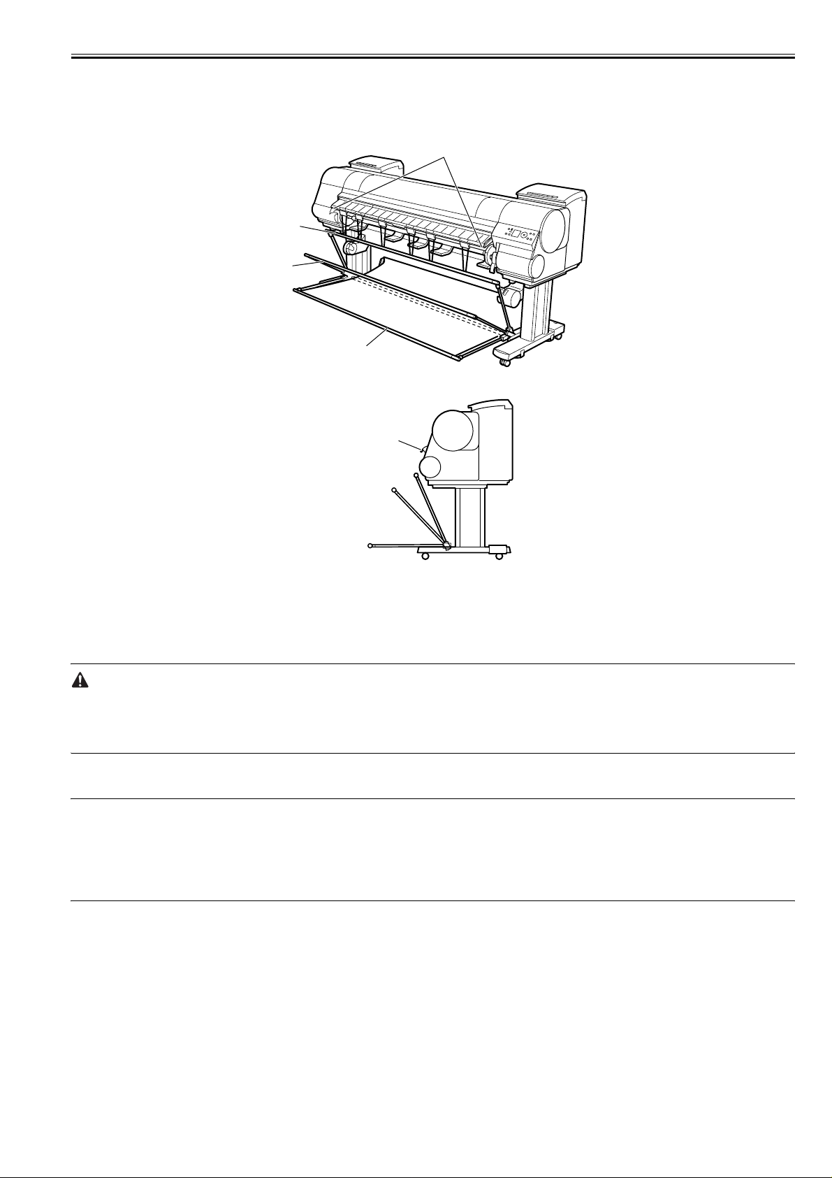
Chapter 1
1.6.4 Basket Unit
iPF9000 / iPF9000S / iPF9100
The Basket Unit(output stacker) can be installed at four positions, as shown.
[2]
[1]
[3]
[4]
[2]
[1]
0017-9389
[4]
F-1-25
[3]
F-1-26
[1] When storing printed documents on the Output Stacker, set it to this position.
[2] When the Output Stacker is not used, set it to this position.
[3] When printing on large and stiff sheets, or when the Media Take-up Unit is used, or when the Output Stacker is stored for long periods, lower it to this position
for storage.
When using the Output Stacker again after storage, reattach the Basket Rod on the front of the Output Stacker to the tips of the left and right Basket Rods and pull
the side rods out completely.
[4] When printing banners or when printing on delicate paper, set it to this position.
- When storing printed documents on the Output Stacker, always use it in position [1]. If you do not, printed documents may n ot be dropped into the Output Stacker,
and the printed surface may become soiled.
- The Output Stacker can hold one sheet. When printing multiple pages, remove each sheet after it is printed.
- Before using the Output Stacker, rem ove the Rewind Spool. If you do not, it may prevent printed documents from being held correctly, and it they may be
scratched.
a. Using the Output Stacker in the position for ejection in the front of the printer
You can also set the Output Stacker to the following position when printing banners or when printing on delicate paper.
MEMO:
- Always choose [Cutting Mode] > [Eject] in the main menu when the Output Stacker is in the position for ejection in the front of the printer. If you choose [Automatic], printed documents may be damaged.
- During ejection in the front of the printer, be especially careful when using delicate paper or paper that curls easily.
- With some types of paper, the leading edge may curl or bend during ejection. In this case, straighten out the paper. Printed documents may be damaged if the paper
is curled or bent.
- Some types of paper may get caught between the Ejection Guide and Output Stacker during ejection. In this case, free the paper from where it is caught. Printed
documents may be damaged if the paper gets caught.
1-71
Page 84
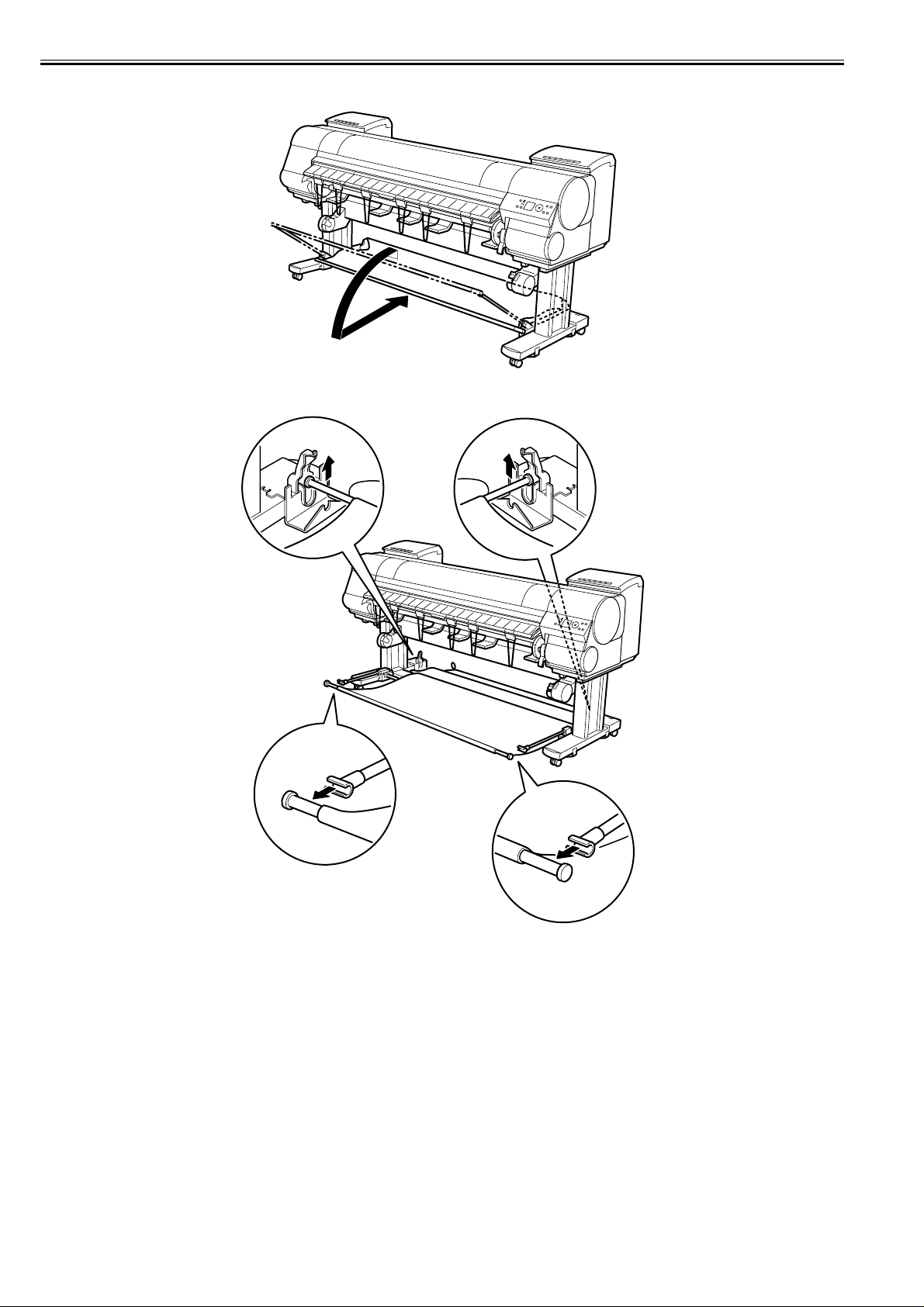
Chapter 1
1) Lift the Basket Rod gently to release the lock, lower the stacker toward the front, and push it all the way back.
F-1-27
2) Remove the front Basket Rod from the left and right Basket Rods, and remove the back Basket Rod and the black cord from the Rod Holder.
1-72
F-1-28
Page 85
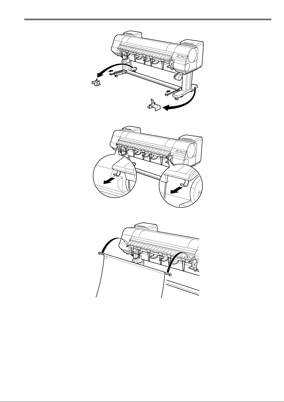
3) Store the left and right Basket Rods. Next, remove the Rod Holder Adapter, leaving the Rod Holder attached, and put it in front of the printer.
F-1-29
4) Pull out the Basket Hooks from the left and right side of the Ejection Guide.
Chapter 1
F-1-30
5) Attach the Basket Rod to the Basket Hooks so that the white tag of the Basket Cloth is on the left side.
F-1-31
1-73
Page 86
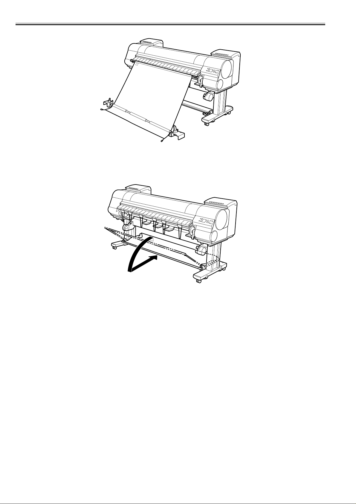
Chapter 1
6) Form the Basket Cloth into a sloping shape to make it taut, and attach the middle Basket Rod to the Rod Holder.
F-1-32
b. Stowing the Output Stacker
Stow the Output Stacker if you will use the Media Take-up Unit or if you will not use the Output Stacker for an extended period.
1) Lift the front Basket Rod gently to release the lock, lower the stacker toward the front, and push it all the way back.
F-1-33
1-74
Page 87
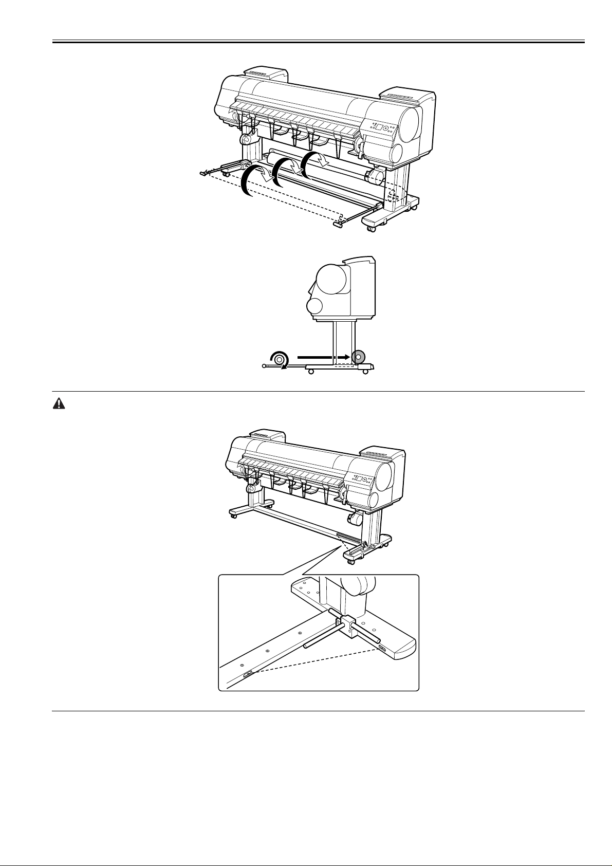
2) Remove the front Basket Rod from the left and right Basket Rods. Roll up the Basket Cloth and put it at the back of the Bottom Stand Stay.
F-1-34
Chapter 1
F-1-35
Arrange the Basket Cloth and Basket Rod so they do not interfere with the Media Take-up Sensor.
F-1-36
1-75
Page 88

Chapter 1
3) Push in the left and right Basket Rods toward the back all the way, until they stop.
F-1-37
1-76
Page 89
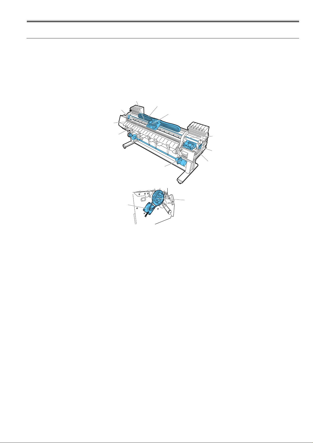
1.7 Safety and Precautions
1.7.1 Safety Precautions
Chapter 1
1.7.1.1 Moving Parts
iPF9000 / iPF9000S / iPF9100
Be careful not to get your hair, clothes, or accessories caught in the moving parts of the printer.
These include the carriage unit activated by the carriage motor, carriage belt, ink tube and flexible cable; feed motor-driven feed roller and pinch roller; and purge
motor-driven purge unit.
To prevent accidents, the upper cover of the printer is locked during printing so that itdoes not open. If the upper cover is opened in the online/offline mode, the
carriage motor, feed motor, and other driving power supplies are turned off.
0012-6284
[2]
[3]
[5]
[4]
[8]
[9]
[1]
[6]
[7]
[12]
[11]
[10]
F-1-38
T-1-29
[1] Carriage belt [7] Purge unit
[2] Ink tube [8] Pinch roller
[3] Flexible cable [9] Feed roller
[4] Carriage unit [10] Feed unit
[5] Carriage motor [11] Feed motor
[6] Lift unit [12] Media take-up unit
1-77
Page 90
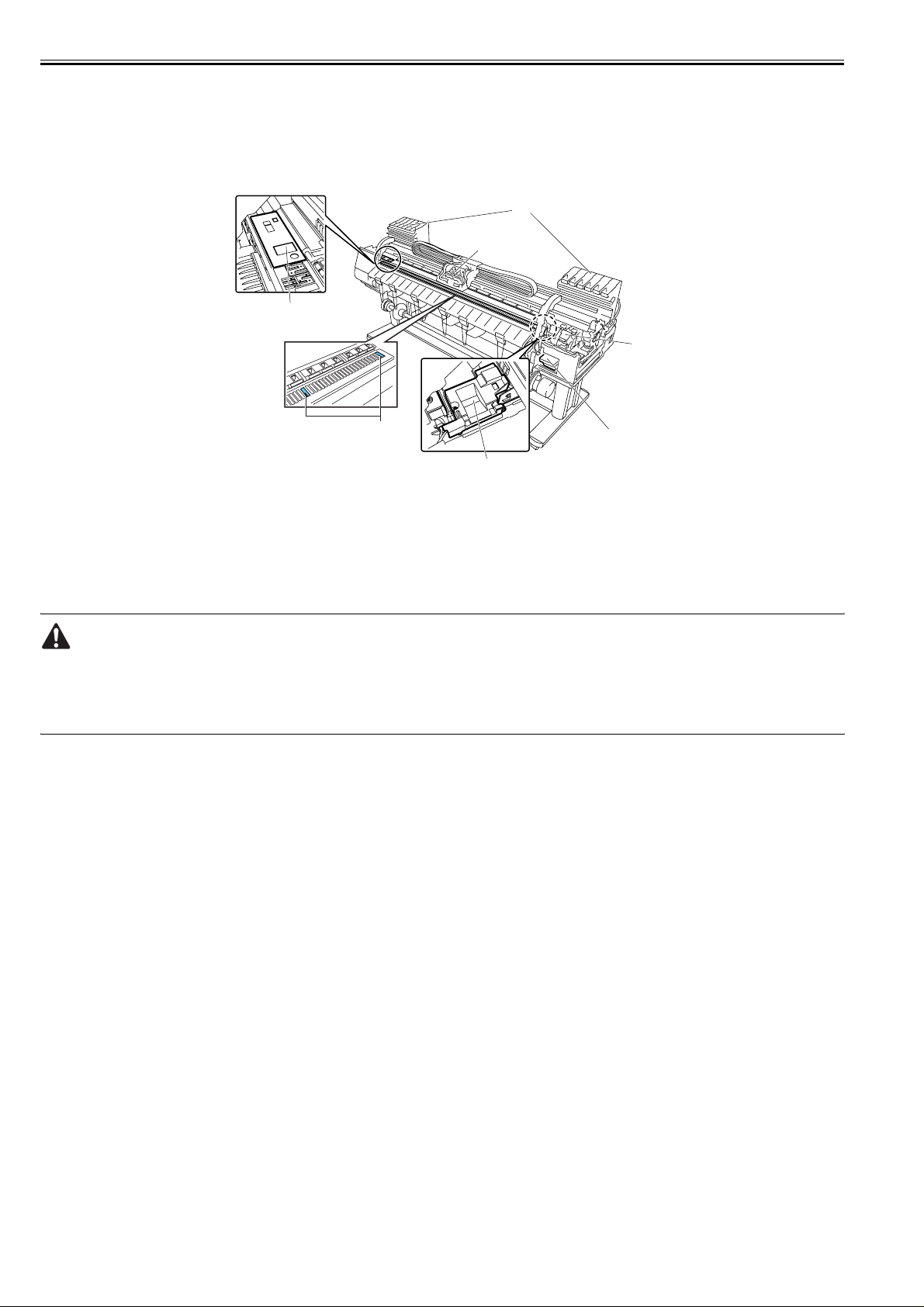
Chapter 1
1.7.1.2 Adhesion of Ink
iPF9000 / iPF9000S / iPF9100
1. Ink passages
Be careful not to touch the ink passages of the printer or to allow ink to stain the workbench, hands, clothes or the printer under repair.
The ink flows through the ink tank unit, carriage unit, purge unit, maintenance-jet tray, borderless print ink groove, maintenance cartridge and the ink tubes that
relay ink to each unit.
[5]
[4]
[1]
[3]
[6]
[1]
F-1-39
T-1-30
[1] Maintenance-jet tray [4] Carriage unit
[2] Maintenance cartridge [5] Ink tank unit
[3] Purge unit [6] Borderless print ink groove
[2]
0014-0264
Although the ink is not harmful to the human body, it contains organic solvents.
Avoid getting the ink in your mouth or eyes.
Flush well with water and see a doctor if contact occurs.
In case of accidental ingestion of a large quantity, call a doctor immediately.
Since this ink contains pigment, stains will not come out of clothing.
1-78
Page 91

Chapter 1
2. Ink mist
Since the printhead prints by squirting ink onto the media, a minute amount of ink mist is generated in the printing unit during printing. The ink mist is collected
in the printer by the airflow. However, uncollected ink mist may stain the platen unit, carriage unit, main rail unit, external unit, or purge unit.
These stains may soil the print media or hands and clothes when servicing the printer, wipe them off carefully with a soft, well-wrung damp cloth.
[2]
[1]
[3]
F-1-40
T-1-31
[1] Purge unit
[2] Upper cover
[3] Platen unit/Carriage unit/Main rail unit
1-79
Page 92
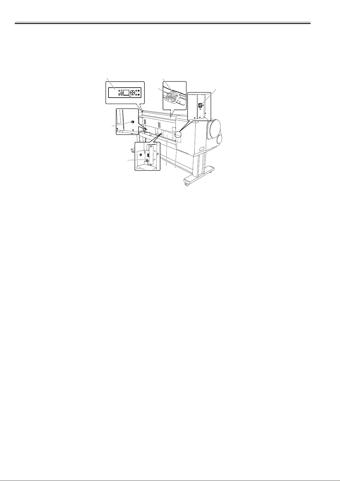
Chapter 1
1.7.1.3 Electrical Parts
iPF9000 / iPF9000S / iPF9100
0012-6287
The electrical unit of the printer is activated when connected to the AC power supply.
At the rear of the printer are the main controller, power supply, interface connector, and optional media take-up unit connector. The head relay PCB and carriage
relay PCB are incorporated in the carriage unit, and the operation panel is located on the upper right cover.
When servicing the printer with the cover removed, be extremely careful to avoid electric shock and shorting contacts.
[1]
Power
Information
Online Data
Message
Cleaning
(3sec.)
Menu
Stop
(1sec.)
Load/Eject
[3]
[2]
[4]
[8]
[7]
[6]
[5]
F-1-41
T-1-32
[1] Operation panel [5] Power Supply
[2] Carriage relay PCB [6] Main controller PCB
[3] Head relay PCB [7] Interface connector
[4] AC inlet [8] Media take-up unit connector
1-80
Page 93
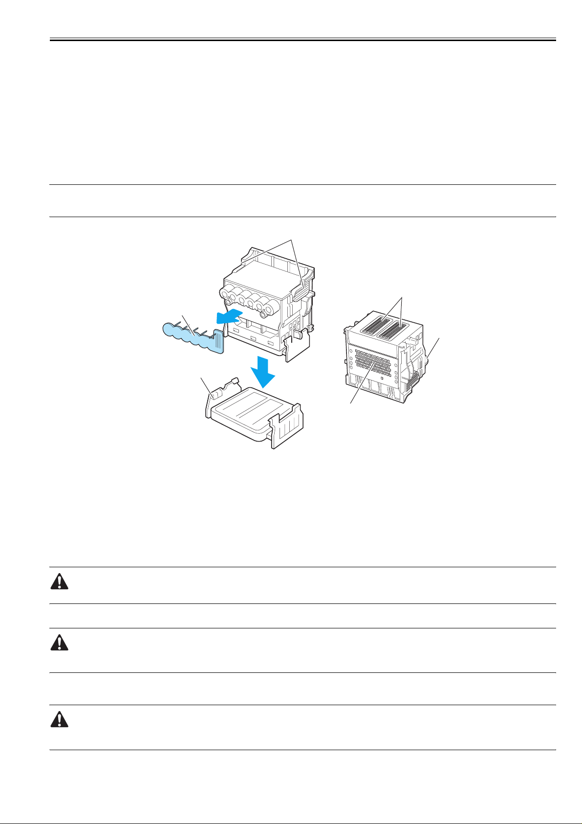
1.7.2 Other Precautions
Chapter 1
1.7.2.1 Printhead
iPF9000 / iPF9000S / iPF9100
1. How to Handle the Printhead
Do not open the printhead package until you are ready to install the head.
When installing the printhead in the printer, hold the knob[1] and then remove the protective cap 1[2] and protective cap 2[3] in that order.
Do not reattach the protective cap 2[3] to the printhead because the cap may damage the nozzles[4].
To prevent the nozzles from getting clogged with foreign matter or dried ink, install the printhead immediately after you remove the protective caps.
Also make sure to press down the locking lever of the printhead until you feel a click.
In addition, to prevent clogging of the nozzles with foreign matter and improper supply of ink, never touch the nozzles[4] or ink port[6], or wipe it with tissue paper
or anything else.
Do not touch Electrical contact[5].
Also, never attempt to disassemble/reassemble the printhead or wash it with water.
MEMO:
If the nozzles are clogged or an ink suction problem occurs, white lines can appear on the printout a constant frequency or color dulling can occur. If this problem
is not resolved by cleaning operations, replace the printhead with a new one.
0013-1937
[1]
[4]
[2]
[6]
[3]
[5]
F-1-42
T-1-33
[1] Knob [4] Nozzles
[2] Protective cap 1 [5] Electrical contact
[3] Protective cap 2 [6] Ink port
2. Capping
The printer will perform the capping operation when printing has ended or during standby due to an error, in order to protect the printhead and avoid ink leakage.
If the power cord is accidentally unplugged, turn off the Power button, reconnect the power cord, and then turn on the Power button. Confirm that the printer starts
up properly and enters to the "Online" or "Offline" status, and then power off the printer using the Power button.
Improper "capping operation" may cause clogged nozzles due to dried ink or ink leakage from the printhead.
3. When the printer is not used for a long time
Keep the printhead installed in the printer even when it is not used for an extended period of time.
If the printhead is left uninstalled, a printing failure may arise from closed nozzles due to depositing of foreign matter or dried ink when it is reinstalled.
Even if the head remains installed, the nozzle may dry out and cause a printing failure if the ink is drained for transport.
4. Conductivity of Ink
The ink used in this printer is electrically conductive. If ink leaks to into the mechanical unit, wipe clean with a soft, well-wrung damp cloth. If ink leaks onto
electrical units, wipe them completely using tissue paper. If you cannot remove ink completely, replace the electrical units with new ones.
If electrical units are powered with ink leaked onto them, the units may damage.
Never connect the power cord when ink has leaded onto the electrical units.
1-81
Page 94
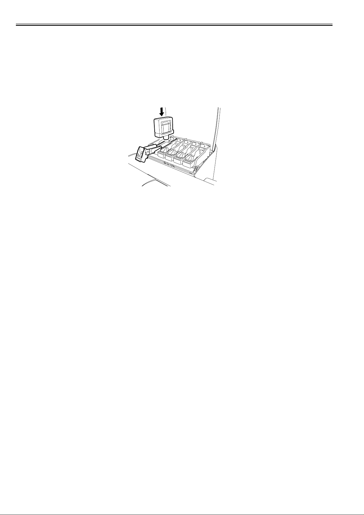
Chapter 1
1.7.2.2 Ink tank
iPF9000 / iPF9000S / iPF9100
0012-6292
1. Unpacking the Ink Tank
Do not unpack the ink tank until you are ready to install it.
When installing the ink tank, be sure to shake it slowly 7 to 8 times before unpacking it. Otherwise, the ink ingredients may precipitate and degrade the print quality.
To prevent foreign matter from entering the ink port, installed the unpacked ink tank in the printer immediately.
2. Handling the Ink Tank
To prevent foreign matter from entering the ink flow path and causing ink suction and printing problems, never touch the ink port and contacts of the ink tank.
When you press down the ink tank cover, the needle enters the ink port, allowing ink to flow between the printer and ink tank.
Do not raise or lower the ink tank cover except when replacing the ink tank.
F-1-43
1-82
Page 95
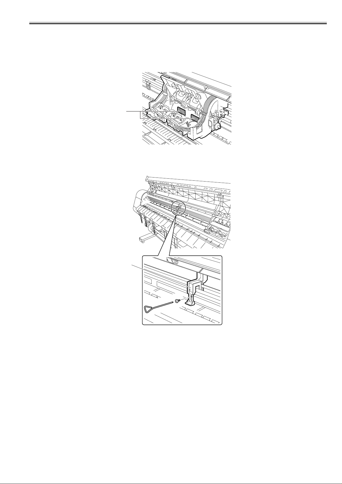
Chapter 1
1.7.2.3 Handling the Printer
iPF9000 / iPF9000S / iPF9100
0012-6294
1. Precautions against Static Electricity
Certain clothing may generate static electricity, causing an electrical charge to build up on your body. Such a charge can damage electrical devices or change their
electrical characteristics.
In particular, never touch the printhead contacts[1].
[1]
F-1-44
2. Fixing the Carriage
After completion of printing, the carriage is mechanically locked by the lock arm in the purge unit at the same moment the printhead is capped.
Before transporting the printer, secure the carriage at its home position using belt stoppers[1] so that the carriage does not become separated from the lock arm and
damage or ink does not leak.
[1]
F-1-45
1-83
Page 96
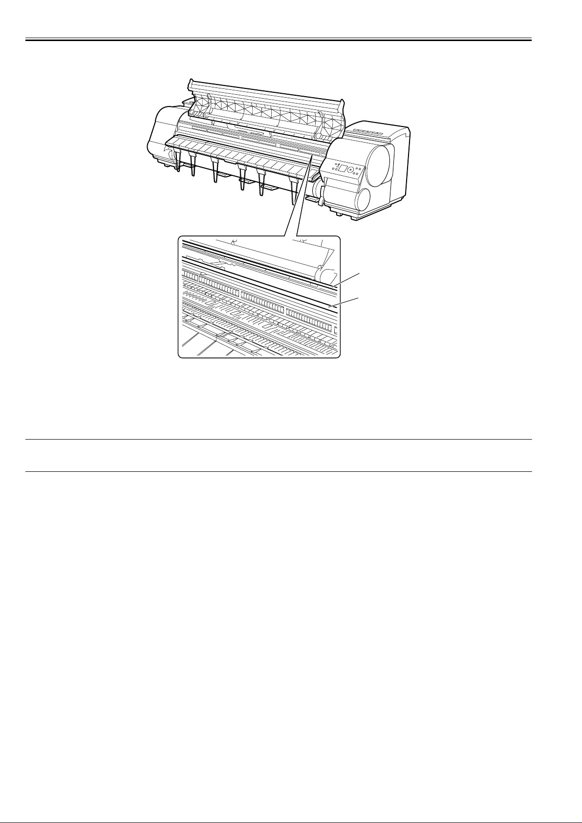
Chapter 1
3. Contact of Linear Scale/Carriage Shaft
Please do not touch a linear scale and the carriage shaft when the inside of the top cover is opened, and execute maintenance.
When touching a linear scale and the carriage shaft, it might cause defective movement of the carriage and a defective print.
[1]
[2]
F-1-46
[1] Linear Scale
[2] Carriage Shaft
4. Replacing the maintenance cartridge
When the maintenance cartridge detects that tank is full, the "Repl. Maint. C" error appears. In this case the maintenance cartridge must be replaced.
The printer will not operate until the error is cancelled.
Be careful that the waste ink does not splash when you remove the used maintenance cartridge from the printer.
MEMO:
This printer has an EEPROM in the maintenance cartridge and the maintenance cartridge status is controlled by the main controller PCB which reads and writes
the content of that EEPROM. Therefore, initializing the counter information will not be needed when the maintenance cartridge is replaced.
5. Refilling the ink
After removing the ink in the printer according to the automatic or manual ink draining procedure to disassemble, reassemble, or transport/ship the printer, refill
the ink as soon as possible upon completion of those tasks.
If the ink remaining in the printer after the removal has dried up, the ink deposits on the surfaces of the components may cause damage or abnormal operation.
1-84
Page 97

1.7.3 Precautions When Servicing Printer
Chapter 1
1.7.3.1 Notes on the Data Stored in the Printer
iPF9000 / iPF9000S / iPF9100
This printer counts the print length, number of ink tank replace ments, carriage driving time, nu mber of cleaning operations, numb er o f cutter oper ations, and s o o n
and stores them in the main controller's EEPROM as a COUNTER in Service mode.
COUNTER provides important information about the printer usage status.
You can check this information by printing it in the service mode or displaying it on the display.
0013-5942
Following the precautions below when servicing the printer.
(1) Repairing/replacing the PCB
When replacing the main controller, follow the specified replacement procedure.
For the main controller replacement procedure, see "Disassembly/Reassembly" > "Points to Note on Disassembly and Reassembly" > "Boards".
(2) After replacing the carriage unit
The information about the carriage driving time arises in the carriage unit. After replacing the carriage unit, select INITIALIZE > CARRIAGE in the service mode
to initialize the information about the carriage driving time.
(3) After replacing the purge unit
The information about the number of cleanings arises in the purge unit. After replacing the purge unit, select [INITIALIZE] > [PURGE] in the service mode to
initialize (clear) the information about the number of cleanings.
(4) On replacement of supplies
After supplies have been replaced, execute [INITIALIZE] > [PARTS COUNTER] > [PARTS xx] in service mode to initialize (clear) the parts counter information.
For the consumable parts, see "Maintenance" > "Consumable Parts".
You cannot check the counter information once it is initialized (cleared). Be careful not to initialize the counter information before checking it.
You cannot modify the counter information from the operation panel.
1.7.3.2 Confirming the Firmware Version
iPF9000 / iPF9000S / iPF9100
0013-5945
Firmware has been downloaded to the main controller.
When you have replaced the main controller, check that the firmware is the latest version. If not, update it to the latest version.
Reference:
For how to up update the main controller, refer to "TROUBLESHOOTING" > "Update".
1.7.3.3 Precautions against Static Electricity
iPF9000 / iPF9000S / iPF9100
Certain clothing may generate static electricity, causing an electrical charge to build up on your body. Such a charge can damage electrical devices.
To prevent this, discharge any static buildup by touching a grounded metal fitting before you start disassembling the printer.
1.7.3.4 Precautions for Disassembly/Reassembly
iPF9000 / iPF9000S / iPF9100
The precautions for disassembly/reassembly are described in "Disassembly/Reassembly".
1.7.3.5 Self-diagnostic Feature
iPF9000 / iPF9000S / iPF9100
The printer has a self-diagnostic feature to analyze hardware problems.
The self-diagnosis result is shown on the display and indicated by lamps.
For detailed information, see "Error Codes".
1.7.3.6 Disposing of the Lithium Battery
iPF9000 / iPF9000S / iPF9100
The main controller PCB of this printer is equipped with a lithium battery to back up various data.
Risk of explosion if battery is replaced by an incorrect type.
Dispose of used batteries according to the instructions.
"For CA, USA Only
Included battery contains Perchlorate Material-special handling may apply. See
http://www.dtsc.ca.gov/hazardouswaste/perchlorate/
for detail."
0013-5947
0013-5948
0013-5950
0013-5952
1-85
Page 98

Chapter 1
1-86
Page 99

Chapter 2 TECHNICAL REFERENCE
Page 100

Contents
Contents
2.1 Basic Operation Outline.................................................................................................................................................2-1
2.1.1 Printer Diagram............................................................................................................................................................................ 2-1
2.1.2 Printer Diagram............................................................................................................................................................................ 2-1
2.1.3 Print Signal Sequence .................................................................................................................................................................. 2-3
2.1.4 Print Signal Sequence .................................................................................................................................................................. 2-4
2.1.5 Print Driving ................................................................................................................................................................................ 2-5
2.1.6 Print Driving ................................................................................................................................................................................ 2-7
2.1.7 Print Driving ................................................................................................................................................................................ 2-9
2.2 Firmware......................................................................................................................................................................2-11
2.2.1 Operation Sequence at Power-on............................................................................................................................................... 2-11
2.2.2 Operation Sequence at Power-off .............................................................................................................................................. 2-12
2.2.3 Print Control............................................................................................................................................................................... 2-13
2.2.4 Print Control............................................................................................................................................................................... 2-13
2.2.5 Print Control............................................................................................................................................................................... 2-21
2.2.6 Print Position Adjustment Function........................................................................................................................................... 2-28
2.2.7 Head Management ..................................................................................................................................................................... 2-28
2.2.8 Printhead Overheating Protection Control......... .. ............................. ............................. ............................................................ 2-28
2.2.9 Pause between Pages.................................................................................................................................................................. 2-28
2.2.10 White Raster Skip ............... ................................................................................ ..................................................................... 2-28
2.2.11 Sleep mode............................................................................................................................................................................... 2-28
2.2.12 Hard disk drive......................................................................................................................................................................... 2-28
2.3 Printer Mechanical System ..........................................................................................................................................2-30
2.3.1 Outline........................................................................................................................................................................................ 2-30
2.3.1.1 Outline...........................................................................................................................................................................................................2-30
2.3.2 Ink Passage................................................................................................................................................................................. 2-31
2.3.2.1 Ink Passage....................................................................................................................................................................................................2-31
2.3.2.1.1 Overview of Ink Passage.......................... ... ...................................... ... .................................................................................................2-31
2.3.2.2 Ink Tank Unit ................................................................................................................................................................................................2-32
2.3.2.2.1 Structure of Ink Tank Unit....................................................................................................................................................................2-32
2.3.2.3 Carriage Unit.................................................................................................................................................................................................2-34
2.3.2.3.1 Functions of Carriage unit........................................................... ... .......................................................................................................2-34
2.3.2.3.2 Structure of Carriage Unit.. ... ... ... ...................................... .... ................................................................................................................2-35
2.3.2.4 Printhead .......................................................................................................................................................................................................2-37
2.3.2.4.1 Structure of Printhead............... ...................................... ... ...................................... . .............................................................................2-37
2.3.2.5 Purge Unit .....................................................................................................................................................................................................2-38
2.3.2.5.1 Functions of Purge Unit ........................................................ ... ................................... ..........................................................................2-38
2.3.2.5.2 Structure of Purge Unit ............................................... ... ...................................... ... ... ...........................................................................2-41
2.3.2.6 Maintenance Cartridge ..................................................................................................................................................................................2-43
2.3.2.6.1 Maintenance Cartridge .......................................... ... ... ...................................... ... .................................................................................2-43
2.3.2.7 Air Flow ........................................................................................................................................................................................................2-44
2.3.2.7.1 Air flow ....................................... .... ... ...................................... ... ..........................................................................................................2-44
2.3.3 Paper Path .................................................................................................................................................................................. 2-45
2.3.3.1 Outline...........................................................................................................................................................................................................2-45
2.3.3.1.1 Overview of Paper Path............... .... ...................................... ... .............................................................................................................2-45
2.3.3.2 Paper Path......................................................................................................................................................................................................2-46
2.3.3.2.1 Structure of Feed Roller Unit...... .... ...................................... ... ... ..........................................................................................................2-46
2.3.3.3 Cutter Unit.....................................................................................................................................................................................................2-46
2.3.3.3.1 Structure of Cutter Unit............................................................... ... ... ....................................................................................................2-46
2.4 Printer Electrical System..............................................................................................................................................2-47
2.4.1 Outline........................................................................................................................................................................................ 2-47
2.4.1.1 Overview.......................................................................................................................................................................................................2-47
2.4.1.2 Overview.......................................................................................................................................................................................................2-47
 Loading...