


iR1018
Table of contents
 Loading...
Sep 22 2006
Service Manual
iR1018/1019/1022/1023 Series


Application
This manual has been issued by Canon Inc. for qualified persons to learn technical theory, installation, maintenance, and repair
of products. This manual covers all localities where the products are sold. For this reason, there may be information in this
manual that does not apply to your locality.
Corrections
This manual may contain technical inaccuracies or typographical errors due to improvements or changes in products. When
changes occur in applicable products or in the contents of this manual, Canon will release technical information as the need
arises. In the event of major changes in the contents of this manual over a long or short period, Canon will issue a new edition
of this manual.
The following paragraph does not apply to any countries where such provisions are inconsistent with local law.
Trademarks
The product names and company names used in this manual are the registered trademarks of the individual companies.
Copyright
This manual is copyrighted with all rights reserved. Under the copyright laws, this manual may not be copied, reproduced or
translated into another language, in whole or in part, without the written consent of Canon Inc.
COPYRIGHT © 2001 CANON INC.
Printed in Japan
Caution
Use of this manual should be strictly supervised to avoid disclosure of confidential information.
Introduction
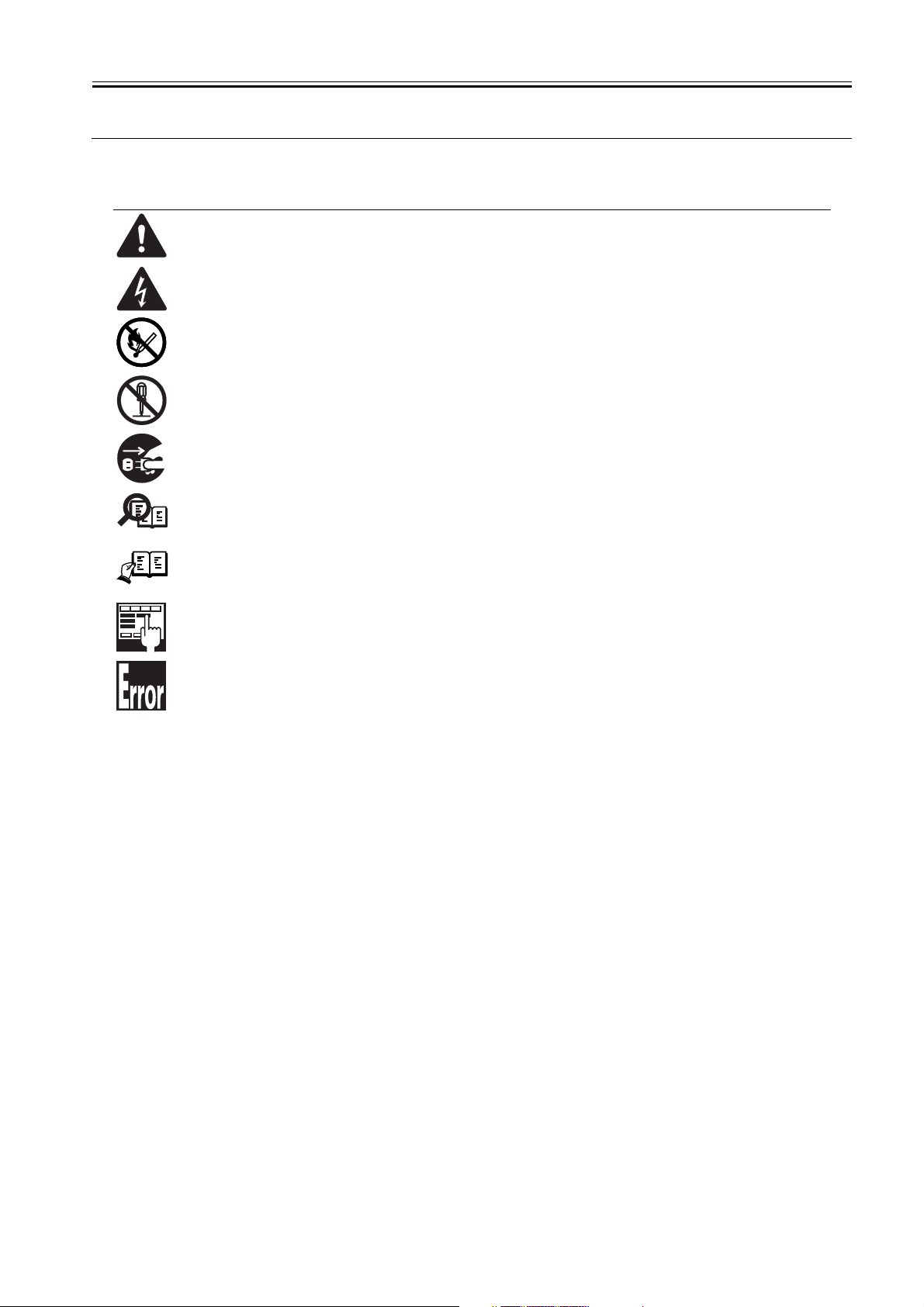
Symbols Used
This documentation uses the following symbols to indicate special information:
Symbol Description
Indicates an item of a non-specific nature, possibly classified as Note, Caution, or Warning.
Indicates an item requiring care to avoid electric shocks.
Indicates an item requiring care to avoid combustion (fire).
Indicates an item prohibiting disassembly to avoid electric shocks or problems.
Indicates an item requiring disconnection of the power plug from the electric outlet.
Indicates an item intended to provide notes assisting the understanding of the topic in question.
Indicates an item of reference assisting the understanding of the topic in question.
Provides a description of a service mode.
Provides a description of the nature of an error indication.
Memo
REF.

Introduction
The following rules apply throughout this Service Manual:
1. Each chapter contains sections explaining the purpose of specific functions and the relationship between electrical and mechanical systems with refer-
ence to the timing of operation.
In the diagrams, represents the path of mechanical drive; where a signal name accompanies the symbol , the arrow indicates the
direction of the electric signal.
The expression "turn on the power" means flipping on the power switch, closing the front door, and closing the delivery unit door, which results in
supplying the machine with power.
2. In the digital circuits, '1'is used to indicate that the voltage level of a given signal is "High", while '0' is used to indicate "Low".(The voltage value, how-
ever, differs from circuit to circuit.) In addition, the asterisk (*) as in "DRMD*" indicates that the DRMD signal goes on when '0'.
In practically all cases, the internal mechanisms of a microprocessor cannot be checked in the field. Therefore, the operations of the microprocessors
used in the machines are not discussed: they are explained in terms of from sensors to the input of the DC controller PCB and from the output of the
DC controller PCB to the loads.
The descriptions in this Service Manual are subject to change without notice for product improvement or other purposes, and major changes will be com-
municated in the form of Service Information bulletins.
All service persons are expected to have a good understanding of the contents of this Service Manual and all relevant Service Information bulletins and be
able to identify and isolate faults in the machine."


Contents
Contents
Chapter 1 Introduction
1.1 System Construction .................................................................................................................................. 1- 1
1.1.1 System Configuration ..............................................................................................................................................1- 1
1.2 Product Specifications ................................................................................................................................ 1- 4
1.2.1 Names of Parts........................................................................................................................................................1- 4
1.2.1.1 External View (Front) ............................................................................................................................................................... 1- 4
1.2.1.2 External View (Rear) ................................................................................................................................................................ 1- 4
1.2.1.3 Cross-Section (Main body) ...................................................................................................................................................... 1- 5
1.2.1.4 Cross Section (ADF) ................................................................................................................................................................ 1- 6
1.2.2 Using the Machine...................................................................................................................................................1- 7
1.2.2.1 Turning On the Power Switch .................................................................................................................................................. 1- 7
1.2.2.2 When Turning Off the Main Power Switch ............................................................................................................................... 1- 8
1.2.2.3 Control Panel ......................................................................................................................................................................... 1- 10
1.2.3 User Mode Items ...................................................................................................................................................1- 11
1.2.3.1 COMMON SETTINGS ........................................................................................................................................................... 1- 11
1.2.3.2 COPY SETTINGS .................................................................................................................................................................. 1- 11
1.2.3.3 TX/RX SETTINGS ................................................................................................................................................................. 1- 12
1.2.3.4 ADDRESS BOOK SET. ......................................................................................................................................................... 1- 12
1.2.3.5 PRINTER SETTINGS ............................................................................................................................................................ 1- 14
1.2.3.6 TIMER SETTINGS ................................................................................................................................................................. 1- 14
1.2.3.7 ADJUST./CLEANING............................................................................................................................................................. 1- 15
1.2.3.8 REPORT SETTINGS ............................................................................................................................................................. 1- 15
1.2.3.9 SYSTEM SETTINGS ............................................................................................................................................................. 1- 15
1.2.4 Maintenance by the User.......................................................................................................................................1- 17
1.2.4.1 User Maintenance Items ........................................................................................................................................................ 1- 17
1.2.4.2 Cleaning ................................................................................................................................................................................. 1- 17
1.2.5 Safety ....................................................................................................................................................................1- 19
1.2.5.1 Safety of Toner ...................................................................................................................................................................... 1- 19
1.2.5.2 Safety of the Laser Light ........................................................................................................................................................ 1- 19
1.2.5.3 CDRH Regulations................................................................................................................................................................. 1- 19
1.2.5.4 Handling the Laser Unit ......................................................................................................................................................... 1- 19
1.2.5.5 Point to Note about Fire ......................................................................................................................................................... 1- 20
1.2.5.6 Cautions as to the replacement and disposal of lithium battery............................................................................................. 1- 20
1.2.6 Product Specifications ...........................................................................................................................................1- 21
1.2.6.1 Product Specifications ........................................................................................................................................................... 1- 21
1.2.6.2 ADF Specifications................................................................................................................................................................. 1- 22
1.2.6.3 Fax Specifications .................................................................................................................................................................. 1- 23
1.2.7 Function List ..........................................................................................................................................................1- 23
1.2.7.1 Print Speed (iR1018/iR1018J/1019/iR1019J)) ....................................................................................................................... 1- 23
1.2.7.2 Print Speed (iR1022/1022A/1022F/1022i/1022iF/1022J/1022N/iR1023/1023N/1023iF)....................................................... 1- 24
1.2.7.3 Types of Paper....................................................................................................................................................................... 1- 24
Chapter 2 Installation
2.1 Installing the Card Reader .......................................................................................................................... 2- 1
2.1.1 Points to Note ..........................................................................................................................................................2- 1
2.1.2 Checking the Contents ............................................................................................................................................2- 1
2.1.3 Installation Procedure..............................................................................................................................................2- 3
2.1.4 Registering the Card IDs ....................................................................................................................................... 2- 12
Chapter 3 Basic Operation
3.1 Construction ............................................................................................................................................... 3- 1
3.1.1 Functional Construction...........................................................................................................................................3- 1

Contents
3.1.2 Functional Block Diagram........................................................................................................................................3- 2
3.1.3 Image Processor PCB .............................................................................................................................................3- 2
3.1.4 DC Controller PCB...................................................................................................................................................3- 3
3.1.5 Analog Processor PCB ............................................................................................................................................3- 4
3.1.6 Power Supply PCB ..................................................................................................................................................3- 4
3.1.7 Relay PCB ...............................................................................................................................................................3- 4
3.1.8 Control Panel PCB...................................................................................................................................................3- 4
3.1.9 NCU PCB (if equipped with fax functions) ...............................................................................................................3- 4
3.1.10 Network PCB (if equipped with network functions) ................................................................................................3- 4
3.1.11 Modular Jack PCB (if equipped with fax functions)................................................................................................3- 4
3.1.12 Modem PCB (if equipped with fax functions) .........................................................................................................3- 4
3.2 Basic Sequence ......................................................................................................................................... 3- 6
3.2.1 Basic Sequence.......................................................................................................................................................3- 6
Chapter 4 Original Exposure System
4.1 Construction ............................................................................................................................................... 4- 1
4.1.1 Specifications, Control Methods, and Functions......................................................................................................4- 1
4.1.2 Major Components...................................................................................................................................................4- 1
4.2 Basic Sequence ......................................................................................................................................... 4- 2
4.2.1 Basic Sequence at Power-on...................................................................................................................................4- 2
4.2.2 Basic Sequence after Depression of Start Key (Book mode, One Sheet of original) ..............................................4- 2
4.2.3 Basic Sequence after Depression of Start Key (ADF Mode, One Sheet of Original)...............................................4- 3
4.3 Various Control........................................................................................................................................... 4- 3
4.3.1 Enlargement/Reduction ...........................................................................................................................................4- 3
4.3.1.1 Magnification Change in Vertical Scan Direction ..................................................................................................................... 4- 3
4.3.1.2 Magnification Change in Horizontal Scan Direction ................................................................................................................. 4- 3
4.3.2 Dirt Sensor Control ..................................................................................................................................................4- 4
4.3.2.1 Outline...................................................................................................................................................................................... 4- 4
4.4 Parts Replacement Procedure ................................................................................................................... 4- 6
4.4.1 Copyboard glass......................................................................................................................................................4- 6
4.4.1.1 Removing the Copyboard Glass .............................................................................................................................................. 4- 6
4.4.1.2 Procedure after Replacing the Copyboard Glass (equipped with SEND functions) ................................................................ 4- 6
4.4.2 Reader Controller PCB ............................................................................................................................................4- 6
4.4.2.1 Removing the Analog Processor PCB ..................................................................................................................................... 4- 6
4.4.3 Scanner Motor .........................................................................................................................................................4- 6
4.4.3.1 Removing the Reader Motor .................................................................................................................................................... 4- 6
4.4.4 Contact sensor.........................................................................................................................................................4- 6
4.4.4.1 Removing the Contact Sensor ................................................................................................................................................. 4- 6
4.4.4.2 Procedure after Replacing the CS ........................................................................................................................................... 4- 7
4.4.5 Contact Sensor HP Sensor......................................................................................................................................4- 7
4.4.5.1 Removing the Contact Sensor Home Position Sensor ............................................................................................................ 4- 7
Chapter 5 Laser Exposure
5.1 Construction ............................................................................................................................................... 5- 1
5.1.1 Specifications and Control Mechanism....................................................................................................................5- 1
5.1.2 Main Components....................................................................................................................................................5- 2
5.2 Parts Replacement Procedure ................................................................................................................... 5- 3
5.2.1 Laser Scanner Unit ..................................................................................................................................................5- 3
5.2.1.1 Removing the Laser Scanner Unit .......................................................................................................................................... 5- 3
Chapter 6 Image Formation
6.1 Construction ............................................................................................................................................... 6- 1
6.1.1 Specifications and Control Mechanism....................................................................................................................6- 1
6.1.2 Outline......................................................................................................................................................................6- 2

Contents
6.2 Image Formation Process ..........................................................................................................................6- 3
6.2.1 Reproduction Processes .........................................................................................................................................6- 3
6.3 Parts Replacement Procedure ...................................................................................................................6- 4
6.3.1 Developing Assembly ..............................................................................................................................................6- 4
6.3.1.1 Removing the Developing Unit ................................................................................................................................................ 6- 4
6.3.2 Transfer Charging Roller .........................................................................................................................................6- 4
6.3.2.1 Removing the Transfer Charging Roller .................................................................................................................................. 6- 4
6.3.3 Waste Toner Full Sensor.........................................................................................................................................6- 4
6.3.3.1 Removing the Waste Toner Full Sensor .................................................................................................................................. 6- 4
Chapter 7 Pickup/Feeding System
7.1 Construction ............................................................................................................................................... 7- 1
7.1.1 Outline .....................................................................................................................................................................7- 1
7.2 Detecting Jams ...........................................................................................................................................7- 2
7.2.1 Jam Detection Outline .............................................................................................................................................7- 2
7.2.1.1 Outline...................................................................................................................................................................................... 7- 2
7.2.1.2 Types of Jams.......................................................................................................................................................................... 7- 2
7.3 Cassette Pick-Up Unit ................................................................................................................................ 7- 3
7.3.1 Outline .....................................................................................................................................................................7- 3
7.3.2 Retry Pickup ............................................................................................................................................................ 7- 3
7.3.3 Detecting the Size of Paper.....................................................................................................................................7- 3
7.4 Manual Feed Pickup Unit ...........................................................................................................................7- 4
7.4.1 Outline .....................................................................................................................................................................7- 4
7.4.2 Retry Pickup ............................................................................................................................................................ 7- 4
7.4.3 Detecting the Size of Paper.....................................................................................................................................7- 4
7.5 Duplex Feeding Unit ...................................................................................................................................7- 5
7.5.1 Outline .....................................................................................................................................................................7- 5
7.6 Parts Replacement Procedure ...................................................................................................................7- 6
7.6.1 Pickup Roller ...........................................................................................................................................................7- 6
7.6.1.1 Removing the Cassette Pickup Roller ..................................................................................................................................... 7- 6
7.6.2 Cassette Paper Sensor ...........................................................................................................................................7- 6
7.6.2.1 Removing the Cassette Paper Sensor..................................................................................................................................... 7- 6
7.6.3 Cassette Pickup Solenoid........................................................................................................................................7- 6
7.6.3.1 Removing the Cassette Pickup Solenoid ................................................................................................................................. 7- 6
7.6.4 Manual Pickup Roller...............................................................................................................................................7- 7
7.6.4.1 Removing the Manual Pickup Roller ........................................................................................................................................ 7- 7
7.6.5 Manual Feed Tray paper sensor .............................................................................................................................7- 7
7.6.5.1 Removing the Manual Tray Sensor ......................................................................................................................................... 7- 7
7.6.6 Manual Feed Pickup Solenoid................................................................................................................................. 7- 7
7.6.6.1 Removing the Manual Pickup Solenoid ................................................................................................................................... 7- 7
7.6.7 Manual Separation Pad ...........................................................................................................................................7- 7
7.6.7.1 Removing the Manual Separation Pad .................................................................................................................................... 7- 7
7.6.8 Registration Roller ...................................................................................................................................................7- 8
7.6.8.1 Removing the Registration Roller ............................................................................................................................................ 7- 8
7.6.9 Registration Sensor ...............................................................................................................................................7- 10
7.6.9.1 Removing the Registration Sensor ........................................................................................................................................ 7- 10
7.6.10 Registration Clutch .............................................................................................................................................. 7- 10
7.6.10.1 Removing the Registration Clutch........................................................................................................................................ 7- 10
7.6.11 Feeding Roller .....................................................................................................................................................7- 11
7.6.11.1 Removing the Cassete Feed Roller ..................................................................................................................................... 7- 11
7.6.12 Duplex Pickup Solenoid.......................................................................................................................................7- 11
7.6.12.1 Removing the Duplex Pickup Solenoid ................................................................................................................................ 7- 11
7.6.13 Separation Roller .................................................................................................................................................7- 11
7.6.13.1 Removing the Cassette Separation Roller ........................................................................................................................... 7- 11
Chapter 8 Fixing System

Contents
8.1 Construction ............................................................................................................................................... 8- 1
8.1.1 Specifications, Control Mechanisms, and Functions ...............................................................................................8- 1
8.1.2 Outline......................................................................................................................................................................8- 1
8.2 Various Control Mechanisms ..................................................................................................................... 8- 2
8.2.1 Controlling the Fixing Film Temperature..................................................................................................................8- 2
8.2.1.1 Outline...................................................................................................................................................................................... 8- 2
8.2.1.2 Controlling the Fixing Film Temperature .................................................................................................................................. 8- 2
8.2.1.3 Target Temperatures by Mode ................................................................................................................................................ 8- 2
8.3 Protective Functions................................................................................................................................... 8- 3
8.3.1 Outline......................................................................................................................................................................8- 3
8.3.2 Failure Detection......................................................................................................................................................8- 3
8.4 Parts Replacement Procedure ................................................................................................................... 8- 5
8.4.1 Fixing Unit ................................................................................................................................................................8- 5
8.4.1.1 Removing the Fixing Unit ......................................................................................................................................................... 8- 5
8.4.1.2 Installing the Fixing unit ........................................................................................................................................................... 8- 6
8.4.2 Pressure Roller ........................................................................................................................................................8- 7
8.4.2.1 Removing the Pressure Roller ................................................................................................................................................. 8- 7
8.4.3 Fixing Film................................................................................................................................................................8- 7
8.4.3.1 Removing the Fixing Film Unit ................................................................................................................................................. 8- 7
8.4.4 Fixing Delivery Sensor.............................................................................................................................................8- 8
8.4.4.1 Removing the Delivery Sensor ................................................................................................................................................ 8- 8
Chapter 9 External and Controls
9.1 Control Panel.............................................................................................................................................. 9- 1
9.1.1 Outline......................................................................................................................................................................9- 1
9.2 Fans ........................................................................................................................................................... 9- 1
9.2.1 Outline......................................................................................................................................................................9- 1
9.3 Power Supply System ................................................................................................................................ 9- 2
9.3.1 Power Supply...........................................................................................................................................................9- 2
9.3.1.1 Outline...................................................................................................................................................................................... 9- 2
9.3.1.2 Rated Output of the Power Supply PCB .................................................................................................................................. 9- 2
9.3.2 Protection Function ..................................................................................................................................................9- 3
9.3.2.1 Protective Functions ................................................................................................................................................................ 9- 3
9.4 Parts Replacement Procedure ................................................................................................................... 9- 4
9.4.1 External Covers .......................................................................................................................................................9- 4
9.4.1.1 External Covers ....................................................................................................................................................................... 9- 4
9.4.2 Drive Unit .................................................................................................................................................................9- 7
9.4.2.1 Removing the Main Drive Unit ................................................................................................................................................. 9- 7
9.4.2.2 Removing the Pickup Drive Unit .............................................................................................................................................. 9- 8
9.4.2.3 Removing the Fixing/Duplex Drive Unit ................................................................................................................................... 9- 8
9.4.3 Power Supply Unit ...................................................................................................................................................9- 8
9.4.3.1 Removing the Power Supply PCB ........................................................................................................................................... 9- 8
9.4.4 Control Panel ...........................................................................................................................................................9- 8
9.4.4.1 Removing the Operation Panel Unit ........................................................................................................................................ 9- 8
9.4.5 Image Processor PCB .............................................................................................................................................9- 9
9.4.5.1 Removing the Image Processor PCB ...................................................................................................................................... 9- 9
9.4.5.2 Procedure after Replacing the Image Processor PCB........................................................................................................... 9- 10
9.4.6 NCU PCB...............................................................................................................................................................9- 10
9.4.6.1 Removing the NCU PCB........................................................................................................................................................ 9- 10
9.4.7 Modular Jack PCB .................................................................................................................................................9- 10
9.4.7.1 Removing the Modular Jack PCB .......................................................................................................................................... 9- 10
9.4.8 Modem PCB...........................................................................................................................................................9- 10
9.4.8.1 Removing the Modem PCB ................................................................................................................................................... 9- 10
9.4.9 Network PCB .........................................................................................................................................................9- 11
9.4.9.1 Removing the Network PCB .................................................................................................................................................. 9- 11
9.4.10 Relay PCB............................................................................................................................................................9- 11
9.4.10.1 Removing the Relay PCB .................................................................................................................................................... 9- 11

Contents
9.4.11 Interlock Switch....................................................................................................................................................9- 11
9.4.11.1 Removing the Interlock Switch ............................................................................................................................................. 9- 11
9.4.12 Fans.....................................................................................................................................................................9- 11
9.4.12.1 Removing the Heat Discharge Fan ...................................................................................................................................... 9- 11
9.4.13 Other....................................................................................................................................................................9- 12
9.4.13.1 Removing the Speaker......................................................................................................................................................... 9- 12
Chapter 10 Original Feeding System
10.1 Basic Construcion ...................................................................................................................................10- 1
10.1.1 Outline .................................................................................................................................................................10- 1
10.1.2 Drive Mechanism .................................................................................................................................................10- 1
10.2 Basic Operation ...................................................................................................................................... 10- 2
10.2.1 Outline of Operation Mode...................................................................................................................................10- 2
10.2.2 Document Size Detection ....................................................................................................................................10- 4
10.2.3 Paper Pickup Operation.......................................................................................................................................10- 4
10.2.4 Reversal Operation..............................................................................................................................................10- 4
10.2.5 Delivery Operation ...............................................................................................................................................10- 5
10.3 Detection Jams .......................................................................................................................................10- 7
10.3.1 Outline .................................................................................................................................................................10- 7
10.4 Parts Replacement Procedure................................................................................................................ 10- 8
10.4.1 ADF......................................................................................................................................................................10- 8
10.4.1.1 Removing the ADF............................................................................................................................................................... 10- 8
10.4.2 External Covers ...................................................................................................................................................10- 8
10.4.2.1 Removing the Front Cover ................................................................................................................................................... 10- 8
10.4.2.2 Removing the Rear Cover.................................................................................................................................................... 10- 8
10.4.2.3 Detaching the Open/Close cover ......................................................................................................................................... 10- 8
10.4.2.4 Removing the Pickup Tray ................................................................................................................................................... 10- 9
10.4.3 ADF Drive Unit.....................................................................................................................................................10- 9
10.4.3.1 Removing the Drive Unit ...................................................................................................................................................... 10- 9
10.4.4 Feed Frame Unit..................................................................................................................................................10- 9
10.4.4.1 Removing the Feed Frame Unit ........................................................................................................................................... 10- 9
10.4.5 ADF Motor Unit ..................................................................................................................................................10- 10
10.4.5.1 Removing the ADF Motor................................................................................................................................................... 10- 10
10.4.6 Pick-up/Feed Roller Unit....................................................................................................................................10- 10
10.4.6.1 Removing the Pickup/Feed Roller Unit .............................................................................................................................. 10- 10
10.4.7 Pickup Roller......................................................................................................................................................10- 11
10.4.7.1 Removing the Pickup Roller ............................................................................................................................................... 10- 11
10.4.8 Original Separation Pad.....................................................................................................................................10- 11
10.4.8.1 Removing the Separation Pad ........................................................................................................................................... 10- 11
10.4.9 Feed Roller ........................................................................................................................................................10- 12
10.4.9.1 Removing the Feed Roller ................................................................................................................................................. 10- 12
10.4.10 Original Sensor ................................................................................................................................................10- 12
10.4.10.1 Removing the Document Set Sensor ............................................................................................................................... 10- 12
10.4.11 Separation Rear Sensor ..................................................................................................................................10- 12
10.4.11.1 Removing the Separation Rear Sensor............................................................................................................................ 10- 12
10.4.12 Registration Sensor .........................................................................................................................................10- 12
10.4.12.1 Removing the Registration Sensor................................................................................................................................... 10- 12
10.4.13 Document Edge Sensor...................................................................................................................................10- 12
10.4.13.1 Removing the document Edge Sensor............................................................................................................................. 10- 12
10.4.14 Pick-up Solenoid .............................................................................................................................................. 10- 13
10.4.14.1 Removing the Pickup Solenoid ........................................................................................................................................ 10- 13
10.4.15 Registaration Solenoid.....................................................................................................................................10- 13
10.4.15.1 Removing the Registration Solenoid ................................................................................................................................ 10- 13
10.4.16 Roller Release Solenoid ..................................................................................................................................10- 13
10.4.16.1 Removing the Roller Release Solenoid............................................................................................................................ 10- 13

Contents
Chapter 11 Maintenance and Inspection
11.1 Periodically Replaced Parts.................................................................................................................... 11- 1
11.1.1 Periodically Replaced Parts .................................................................................................................................11- 1
11.2 Durables and Consumables ................................................................................................................... 11- 1
11.2.1 Durables...............................................................................................................................................................11- 1
11.3 Scheduled Servicing Basic Procedure ................................................................................................... 11- 1
11.3.1 Periodeical Service Items.....................................................................................................................................11- 1
Chapter 12 Standards and Adjustments
12.1 Image Adjustments ................................................................................................................................. 12- 1
12.1.1 Image parallelism adjustment ..............................................................................................................................12- 1
12.2 Scanning System.................................................................................................................................... 12- 2
12.2.1 Procedure after Replacing the CS ......................................................................................................................12- 2
12.2.2 Procedure after Replacing the Copyboard Glass (if equipped with SEND functions) ..........................................12- 2
12.3 Electrical Components............................................................................................................................ 12- 2
12.3.1 Procedure after Replacing the Image Processor PCB.........................................................................................12- 2
12.3.2 Actions to Take before All Clearing (Backing up the User Data) .........................................................................12- 2
12.4 ADF ........................................................................................................................................................ 12- 3
12.4.1 Outline..................................................................................................................................................................12- 3
12.4.1.1 Outline.................................................................................................................................................................................. 12- 3
12.4.1.2 Preparing a Test Sheet for Adjustment ................................................................................................................................ 12- 3
12.4.2 Adjusting the Mechanical System ........................................................................................................................12- 3
12.4.2.1 Adjusting the Perpendicularity.............................................................................................................................................. 12- 3
12.4.3 Adjusting the Ellectrical System...........................................................................................................................12- 3
12.4.3.1 Adjusting the Magnification .................................................................................................................................................. 12- 3
12.4.3.2 Adjusting the Horizontal Registration ................................................................................................................................... 12- 3
12.4.3.3 Leading edge registration adjustment .................................................................................................................................. 12- 4
Chapter 13 Correcting Faulty Images
13.1 Making lnitial Checks .............................................................................................................................. 13- 1
13.1.1 Site Environment..................................................................................................................................................13- 1
13.1.2 Checking the Paper..............................................................................................................................................13- 1
13.1.3 Checking the Placement of Paper........................................................................................................................13- 1
13.1.4 Checking the Durables.........................................................................................................................................13- 1
13.1.5 Checking the Units and Functional Systems........................................................................................................13- 1
13.1.6 Others ..................................................................................................................................................................13- 2
13.2 Outline of Electrical Components ........................................................................................................... 13- 3
13.2.1 Clutch/Solenoid....................................................................................................................................................13- 3
13.2.1.1 List of Clutches/Solenoids/Motors/Fans ............................................................................................................................... 13- 3
13.2.2 Sensor..................................................................................................................................................................13- 4
13.2.2.1 List of Sensors ..................................................................................................................................................................... 13- 4
13.2.3 Lamps, Heaters, and Others................................................................................................................................13- 5
13.2.3.1 List of Lamps, Heaters, and Others ..................................................................................................................................... 13- 5
13.2.4 PCBs ....................................................................................................................................................................13- 7
13.2.4.1 List of PCBs ......................................................................................................................................................................... 13- 7
Chapter 14 Self Diagnosis
14.1 Error Code Details .................................................................................................................................. 14- 1
14.1.1 Error Code Details................................................................................................................................................14- 1
14.2 Jam Code ............................................................................................................................................... 14- 2
14.2.1 Jam Codes (Main body) .......................................................................................................................................14- 2
14.2.2 Jam Codes (ADF) ................................................................................................................................................14- 2
14.3 FAX Error Codes .................................................................................................................................... 14- 3

Contents
14.3.1 Outline .................................................................................................................................................................14- 3
14.3.1.1 Error Code Outline ............................................................................................................................................................... 14- 3
14.3.2 User Error Code...................................................................................................................................................14- 3
14.3.2.1 User Error Code ................................................................................................................................................................... 14- 3
14.3.3 Service Error Code ..............................................................................................................................................14- 3
14.3.3.1 Service Error Code............................................................................................................................................................... 14- 3
Chapter 15 Service Mode
15.1 Outline .................................................................................................................................................... 15- 1
15.1.1 Outline of Service Mode ......................................................................................................................................15- 1
15.1.2 Using the Mode....................................................................................................................................................15- 2
15.2 Default settings .......................................................................................................................................15- 2
15.2.1 Service Mode Menus ...........................................................................................................................................15- 2
15.3 Setting of Bit Switch (SSSW) ..................................................................................................................15- 8
15.3.1 Outline .................................................................................................................................................................15- 8
15.3.1.1 Bit Switch Composition ........................................................................................................................................................ 15- 8
15.3.2 SSSW-SW01 .......................................................................................................................................................15- 8
15.3.2.1 List of Functions ................................................................................................................................................................... 15- 8
15.3.2.2 Detailed Discussions of Bit 0................................................................................................................................................ 15- 8
15.3.3 SSSW-SW03 .......................................................................................................................................................15- 8
15.3.3.1 List of Functions ................................................................................................................................................................... 15- 8
15.3.3.2 Detailed Discussions of Bit 7................................................................................................................................................ 15- 8
15.3.4 SSSW-SW04 .......................................................................................................................................................15- 8
15.3.4.1 List of Functions ................................................................................................................................................................... 15- 8
15.3.4.2 Detailed Discussions of Bit 2................................................................................................................................................ 15- 9
15.3.4.3 Detailed Discussions of Bit 3................................................................................................................................................ 15- 9
15.3.4.4 Detailed Discussions of Bit 4................................................................................................................................................ 15- 9
15.3.4.5 Detailed Discussions of Bit 6................................................................................................................................................ 15- 9
15.3.4.6 Detailed Discussions of Bit 7................................................................................................................................................ 15- 9
15.3.5 SSSW-SW05 .......................................................................................................................................................15- 9
15.3.5.1 List of Functions ................................................................................................................................................................... 15- 9
15.3.5.2 Detailed Discussions of Bit 1................................................................................................................................................ 15- 9
15.3.5.3 Detailed Discussions of Bit 2.............................................................................................................................................. 15- 10
15.3.6 SSSW-SW12 .....................................................................................................................................................15- 10
15.3.6.1 List of Functions ................................................................................................................................................................. 15- 10
15.3.7 SSSW-SW13 .....................................................................................................................................................15- 10
15.3.7.1 List of Functions ................................................................................................................................................................. 15- 10
15.3.7.2 Detailed Discussions of Bit 2.............................................................................................................................................. 15- 10
15.3.8 SSSW-SW14 .....................................................................................................................................................15- 11
15.3.8.1 List of Functions ................................................................................................................................................................. 15- 11
15.3.8.2 Detailed Discussions of Bit 2.............................................................................................................................................. 15- 11
15.3.8.3 Detailed Discussions of Bit 4.............................................................................................................................................. 15- 11
15.3.9 SSSW-SW28 .....................................................................................................................................................15- 11
15.3.9.1 List of Functions ................................................................................................................................................................. 15- 11
15.3.9.2 Detailed Discussions of Bit 0.............................................................................................................................................. 15- 11
15.3.9.3 Detailed Discussions of Bit 1.............................................................................................................................................. 15- 11
15.3.9.4 Detailed Discussions of Bit 2.............................................................................................................................................. 15- 11
15.3.9.5 Detailed Discussions of Bit 3.............................................................................................................................................. 15- 11
15.3.9.6 Detailed Discussions of Bit 4.............................................................................................................................................. 15- 11
15.3.9.7 Detailed Discussions of Bit 5.............................................................................................................................................. 15- 11
15.3.10 SSSW-SW30 ...................................................................................................................................................15- 12
15.3.10.1 List of Functions ............................................................................................................................................................... 15- 12
15.3.10.2 Detailed Discussions of Bit 5 ............................................................................................................................................ 15- 12
15.3.11 SSSW-SW34 ...................................................................................................................................................15- 12
15.3.11.1 List of Functions ............................................................................................................................................................... 15- 12
15.3.11.2 Detailed Discussions of Bit 0 ............................................................................................................................................ 15- 12
15.3.11.3 Detailed Discussions of Bit 1 ............................................................................................................................................ 15- 12
15.4 Setting of Menu Switch (Menu)............................................................................................................. 15- 12

Contents
15.4.1 Menu Switch Composition..................................................................................................................................15- 12
15.4.2 <No.005 NL equalizer> ......................................................................................................................................15- 13
15.4.3 <No.006 telephone line monitor>.......................................................................................................................15- 13
15.4.4 <No.007 ATT transmission level>......................................................................................................................15- 13
15.4.5 <No.008 V.34 modulation speed upper limit>....................................................................................................15- 13
15.4.6 <No.009 V.34 data speed upper limit>...............................................................................................................15- 13
15.4.7 <No.010 Frequency of the pseudo CI signal>....................................................................................................15- 13
15.5 Setting of Numeric Parameter (NUMERIC Param.).............................................................................. 15- 13
15.5.1 Numerical Parameter Composition ....................................................................................................................15- 13
15.5.2 <002: RTN transmission condition (1)><003: RTN transmission condition (2)><004: RTN transmission condition (3)>
15- 14
15.5.3 <005: NCC pause length (pre-ID code)> ...........................................................................................................15- 14
15.5.4 <006: NCC pause length (post-ID code)>..........................................................................................................15- 14
15.5.5 <010: line connection identification length> .......................................................................................................15- 14
15.5.6 <011: T.30 T1 timer (for reception)> ..................................................................................................................15- 14
15.5.7 <013: T.30 EOL timer>.......................................................................................................................................15- 14
15.5.8 <015: hooking detection time>...........................................................................................................................15- 14
15.5.9 <016: time length to first response at time of fax/tel switchover> ......................................................................15- 14
15.5.10 <017: pseudo RBT signal pattern ON time length><018: pseudo RBT signal pattern OFF time length (short)><019:
pseudo RBT signal pattern OFF time length (long)> ...............................................................................................15- 14
15.5.11 <020: pseudo CI signal pattern ON time length><021: pseudo CI signal pattern OFF time length (short)><022:
pseudo CI signal pattern OFF time length (long)> ...................................................................................................15- 15
15.5.12 <023: CNG detention level for fax/tel switchover> ...........................................................................................15- 15
15.5.13 <024: pseudo RBT transmission level at time of fax/tel switchover> ...............................................................15- 15
15.5.14 <025: Answering machine connection function signal detection time> ............................................................15- 15
15.5.15 <027: V.21 low-speed flag preamble identification length> ..............................................................................15- 15
15.5.16 <056 - 061: Count type select > .......................................................................................................................15- 15
15.6 Setting of Scanner Functions (SCANNER)........................................................................................... 15- 18
15.6.1 Numeric Parameter Functional configuration.....................................................................................................15- 18
15.6.2 <024:CIS scan position during ADF scanning> .................................................................................................15- 19
15.6.3 <026:Distance from the standby position of CIS to the shading start point> .....................................................15- 19
15.6.4 <031: Vertical scan start position adjustment> ..................................................................................................15- 19
15.6.5 <032: Horizontal scan start position adjustment> ..............................................................................................15- 19
15.6.6 <033: Vertical scan magnification correction> ...................................................................................................15- 19
15.6.7 <034: Horizontal scan magnification correction> ...............................................................................................15- 19
15.6.8 <035: - 036:Reader motor speed change> ........................................................................................................15- 19
15.6.9 <041: Vertical scan start position adjustment (when scanning on a document fed from ADF)>........................15- 19
15.6.10 <042: Horizontal scan start position adjustment (when scanning on a document fed from ADF)>..................15- 19
15.6.11 <043: Horizontal scan end position correction ((copy:scanning on ADF)> ......................................................15- 20
15.6.12 <044: Horizontal scan end position correction (superfine:scanning on ADF)> ................................................15- 20
15.6.13 <045: Horizontal scan end position correction (fine:scanning on ADF)> .........................................................15- 20
15.6.14 <046: Horizontal scan end position correction (standard:scanning on ADF)> .................................................15- 20
15.6.15 <047: Vertical scan magnification correction (when scanning on a document fed from ADF)> .......................15- 20
15.6.16 <048: Horizontal scan magnification correction (when scanning on a document fed from ADF)> ...................15- 20
15.6.17 <054: Pickup motor speed correction (when the ADF is used) > .....................................................................15- 20
15.6.18 <193: ADF special standard-sized paper: LGL misidentification-ready> .........................................................15- 20
15.6.19 <194: ADF special standard-sized paper: LTR misidentification-ready> .........................................................15- 20
15.6.20 <195: ADF special standard-sized paper: LTR_R misidentification-ready> .....................................................15- 20
15.6.21 <213: XYZ correction value (X) of standard white plate> (equipped with SEND functions) .............................15- 21
15.6.22 <214: XYZ correction value (Y) of standard white plate> (equipped with SEND functions) .............................15- 21
15.6.23 <215: XYZ correction value (Z) of standard white plate> (equipped with SEND functions) .............................15- 21
15.7 Setting of Printer Functions (PRINTER) ............................................................................................... 15- 21
15.7.1 Service Soft Switch Settings (PRINTER) ...........................................................................................................15- 21
15.7.1.1 SSSW-SW05...................................................................................................................................................................... 15- 21
15.7.1.2 SSSW-SW14...................................................................................................................................................................... 15- 22
15.7.1.3 SSSW-SW15...................................................................................................................................................................... 15- 22

Contents
15.7.2 Numerin Parameter Settings (Numeric Prama.) ................................................................................................15- 23
15.7.2.1 Numeric Parameter Functional configuration ..................................................................................................................... 15- 23
15.7.2.2 <031: Top registration adjustment (manual feed tray)> ..................................................................................................... 15- 23
15.7.2.3 <032: Top registration adjustment (cassette)>................................................................................................................... 15- 23
15.7.2.4 <033: Top registration adjustment (duplex unit)>............................................................................................................... 15- 23
15.7.2.5 <034: Left-end registration adjustment (manual feed tray)> .............................................................................................. 15- 23
15.7.2.6 <035: Left-end registration adjustment (cassette 1)>......................................................................................................... 15- 23
15.7.2.7 <036: Left-end registration adjustment (cassette 2)>......................................................................................................... 15- 23
15.7.2.8 <039: Left-end registration adjustment (duplex unit)>........................................................................................................ 15- 23
15.7.2.9 <040: Target fixing temperature adjustment (manual feed tray)> ...................................................................................... 15- 23
15.7.2.10 <041: Target fixing temperature adjustment (cassette 1)>............................................................................................... 15- 23
15.7.2.11 <042: Target fixing temperature adjustment (cassette 2)>............................................................................................... 15- 24
15.7.2.12 <051: Target 2-sided temperature adjustment> ............................................................................................................... 15- 24
15.7.2.13 <053: Margin adjustment at the leading edge of the copy> ............................................................................................. 15- 24
15.7.2.14 <054: Margin adjustment at the trailing edge of the copy> .............................................................................................. 15- 24
15.7.2.15 <055: Margin adjustment at the right edge of the copy> .................................................................................................. 15- 24
15.7.2.16 <056: Margin adjustment at the left edge of the copy> .................................................................................................... 15- 24
15.8 Registration of Accessories (ACC) .......................................................................................................15- 25
15.8.1 Accessory Registration ......................................................................................................................................15- 25
15.9 Display of Counter Information (COUNTER) ........................................................................................ 15- 25
15.9.1 Counters ............................................................................................................................................................15- 25
15.9.2 Clearing Counters..............................................................................................................................................15- 25
15.10 Service Report (REPORT) ..................................................................................................................15- 27
15.10.1 Report Output .................................................................................................................................................. 15- 27
15.10.2 System Data List..............................................................................................................................................15- 27
15.10.3 System Dump List............................................................................................................................................15- 27
15.10.4 Counter List......................................................................................................................................................15- 29
15.10.5 Error Log List ...................................................................................................................................................15- 29
15.10.6 Spec List ..........................................................................................................................................................15- 31
15.10.7 Service Label ...................................................................................................................................................15- 32
15.11 Download (DOWNLOAD)....................................................................................................................15- 33
15.11.1 Download .........................................................................................................................................................15- 33
15.12 Initialization of Set Value (CLEAR) ..................................................................................................... 15- 33
15.12.1 Clear ................................................................................................................................................................15- 33
15.13 Error Display (ERROR DISPLAY)....................................................................................................... 15- 33
15.13.1 Error Display ....................................................................................................................................................15- 33
15.14 Display of ROM Information (ROM) ....................................................................................................15- 33
15.14.1 ROM display ....................................................................................................................................................15- 33
15.15 Test Mode (TEST) ..............................................................................................................................15- 34
15.15.1 D-RAM Test<(1) D-RAM TEST>......................................................................................................................15- 34
15.15.2 Scan Test ((2) SCAN TEST)............................................................................................................................15- 34
15.15.3 Print Test ((3) PRINT TEST)............................................................................................................................15- 34
15.15.4 MODEM Test ((4) MODEM TEST) ..................................................................................................................15- 35
15.15.5 FUNCTION TEST <(6) FUNCTION TEST>.....................................................................................................15- 37
15.15.6 Roller cleaning mode ((0) ROLLER CLEAN) ...................................................................................................15- 41
Chapter 16 Upgrading
16.1 Outline .................................................................................................................................................... 16- 1
16.1.1 Overview of Upgrade ...........................................................................................................................................16- 1
16.1.2 Overview of Service Support Tool .......................................................................................................................16- 1
16.2 Making Preparations ...............................................................................................................................16- 1
16.2.1 Registering the System Software ........................................................................................................................16- 1
16.2.2 Connection...........................................................................................................................................................16- 3
16.3 Downloading System Software ............................................................................................................... 16- 4
16.3.1 Downloading System ...........................................................................................................................................16- 4
16.3.1.1 Downloading Procedure ....................................................................................................................................................... 16- 4

Contents
16.3.2 Downloading BOOT .............................................................................................................................................16- 4
16.3.2.1 Downloading Procedure ....................................................................................................................................................... 16- 4
16.3.3 Other Upgrade Methods.......................................................................................................................................16- 9
16.3.3.1 Downloading the PCL Software ........................................................................................................................................... 16- 9
Chapter 17 Service Tools
17.1 Service Tools .......................................................................................................................................... 17- 1
17.1.1 Special Tools........................................................................................................................................................17- 1

Chapter 1 Introduction


Contents
Contents
1.1 System Construction ......................................................................................................................................................1-1
1.1.1 System Configuration .................................................................................................................................................................. 1-1
1.2 Product Specifications....................................................................................................................................................1-4
1.2.1 Names of Parts ............................................................................................................................................................................. 1-4
1.2.1.1 External View (Front) .....................................................................................................................................................................................1-4
1.2.1.2 External View (Rear) ......................................................................................................................................................................................1-4
1.2.1.3 Cross-Section (Main body) ............................................................................................................................................................................. 1-5
1.2.1.4 Cross Section (ADF) .......................................................................................................................................................................................1-6
1.2.2 Using the Machine ....................................................................................................................................................................... 1-7
1.2.2.1 Turning On the Power Switch .........................................................................................................................................................................1-7
1.2.2.2 When Turning Off the Main Power Switch ....................................................................................................................................................1-8
1.2.2.3 Control Panel.................................................................................................................................................................................................1-10
1.2.3 User Mode Items........................................................................................................................................................................ 1-11
1.2.3.1 COMMON SETTINGS ................................................................................................................................................................................1-11
1.2.3.2 COPY SETTINGS ........................................................................................................................................................................................ 1-11
1.2.3.3 TX/RX SETTINGS .......................................................................................................................................................................................1-12
1.2.3.4 ADDRESS BOOK SET. ...............................................................................................................................................................................1-12
1.2.3.5 PRINTER SETTINGS .................................................................................................................................................................................. 1-14
1.2.3.6 TIMER SETTINGS ......................................................................................................................................................................................1-14
1.2.3.7 ADJUST./CLEANING .................................................................................................................................................................................1-15
1.2.3.8 REPORT SETTINGS.................................................................................................................................................................................... 1-15
1.2.3.9 SYSTEM SETTINGS ...................................................................................................................................................................................1-15
1.2.4 Maintenance by the User ........................................................................................................................................................... 1-17
1.2.4.1 User Maintenance Items ................................................................................................................................................................................1-17
1.2.4.2 Cleaning ........................................................................................................................................................................................................1-17
1.2.5 Safety ......................................................................................................................................................................................... 1-19
1.2.5.1 Safety of Toner..............................................................................................................................................................................................1-19
1.2.5.2 Safety of the Laser Light ............................................................................................................................................................................... 1-19
1.2.5.3 CDRH Regulations........................................................................................................................................................................................1-19
1.2.5.4 Handling the Laser Unit ................................................................................................................................................................................1-19
1.2.5.5 Point to Note about Fire ................................................................................................................................................................................1-20
1.2.5.6 Cautions as to the replacement and disposal of lithium battery .................................................................................................................... 1-20
1.2.6 Product Specifications ............................................................................................................................................................... 1-21
1.2.6.1 Product Specifications ...................................................................................................................................................................................1-21
1.2.6.2 ADF Specifications .......................................................................................................................................................................................1-22
1.2.6.3 Fax Specifications ......................................................................................................................................................................................... 1-23
1.2.7 Function List .............................................................................................................................................................................. 1-23
1.2.7.1 Print Speed (iR1018/iR1018J/1019/iR1019J)) ............................................................................................................................................. 1-23
1.2.7.2 Print Speed (iR1022/1022A/1022F/1022i/1022iF/1022J/1022N/iR1023/1023N/1023iF)........................................................................... 1-24
1.2.7.3 Types of Paper...............................................................................................................................................................................................1-24

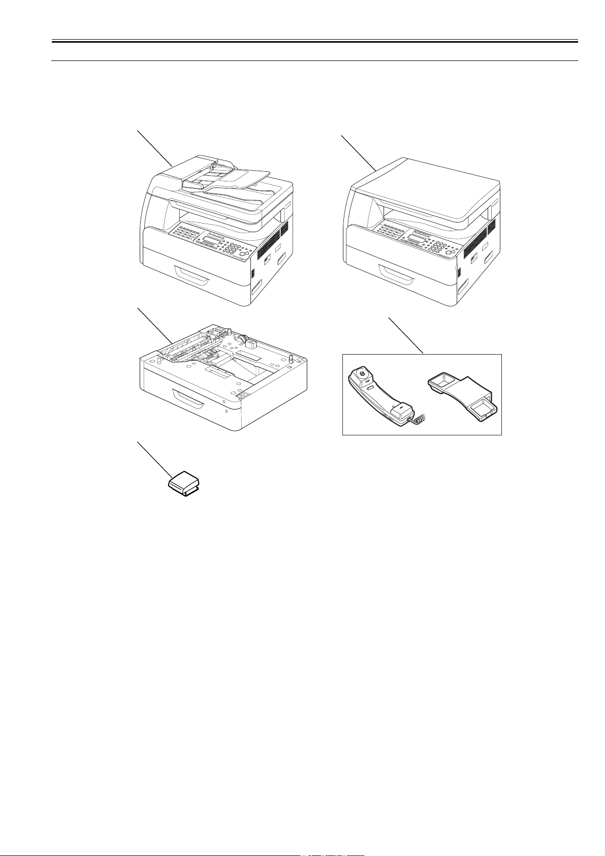
Chapter 1
1-1
1.1 System Construction
1.1.1 System Configuration
0013-1039
/ / / / iR1018 / iR1018J / / iR1022A / iR1022F / iR1022i / iR1022iF /
- Pickup/ Other Accessories
F-1-1
T-1-1
[1] Main body (ADF type)
[2] Main body (copyboard type)
[3] Cassette Feeding Module-N1
[4] Hand Set CT-25
[5] Card Reader-E1 + Card Reader Attachment-D2
[4]
[1]
[3]
[5]
[2]
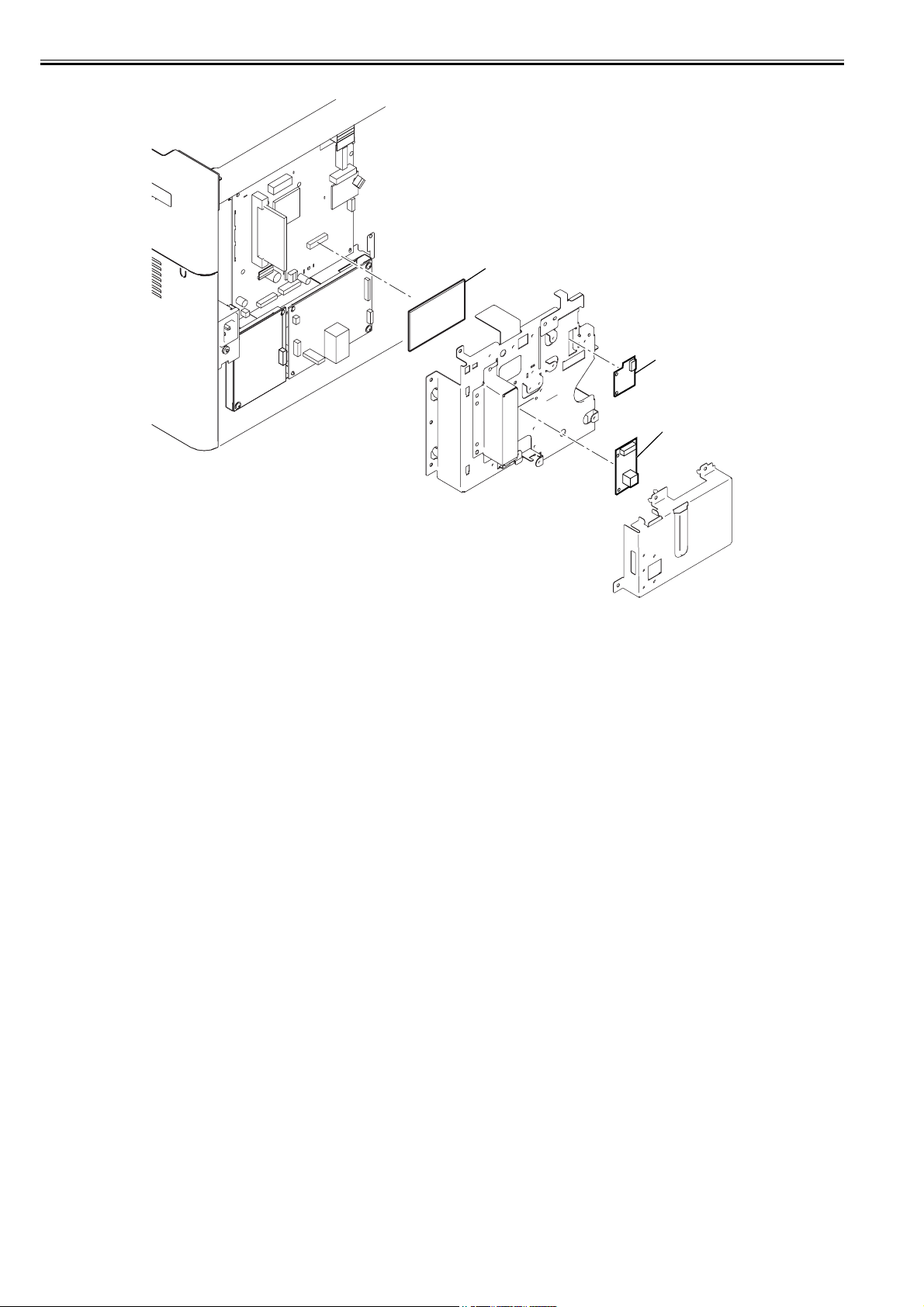
Chapter 1
1-2
- Boards
F-1-2
T-1-2
[1] NW IF Adapter iN-E11
[2] PCL Printer Kit-M1
[3] Serial Interface Board-A1
[1]
[3]
[2]

Chapter 1
1-3
- Option conversion table
T-1-3
Function Model name Product code PCL
Printer Kit-
M1
NW IF
Adapter iN-
E11
Cassette
Feeding
Module-N1
Card
Reader-E1 +
Card Reader
Attachment-
D1
Serial
Interface
Board-A1
Hand Set
CT-25
Copy iR1019J 0460B001AA
0460B002AB
- - Option. Option. Option. -
iR1018J 0460B007AB - - Option. Option. Option. -
iR1018J 0460B003AA - - Option. Option. Option. -
iR1022J 0747B003AA - - Option. Option. Option. -
Copy/Printer/Scanner iR1018 0461B002AB Option Option Option. Option. Option. -
iR1018 0461B007AB Option Option Option. Option. Option. -
iR1018 0461B004AA Option Option Option. Option. Option. -
iR1023 0748B001AA Standard Standard Option. Option. Option. -
iR1022 0748B002AA Option Standard Option. Option. Option. -
iR1022 0748B003AA Option Option Option. Option. Option. -
iR1022 0748B004AA Option Standard Option. Option. Option. -
iR1022 0748B005AA Option Standard Option. Option. Option. -
Copy/Printer/Scanner/
ADF
iR1023N 0463B001AA Option Standard Option. Option. Option. -
iR1022A 0463B002AB Option Standard Option. Option. Option. -
iR1022A 0463B003AB Option Standard Option. Option. Option. -
Copy/Printer/Scanner/
Fax/ADF
iR1022F 0464B002AB Option Standard Option. Option. Option. Option.
iR1022F 0464B008AB Option Standard Option. Option. Option. -
iR1022F 0464B003AA Option Standard Option. Option. Option. -
iR1022F 0464B004AA Option Standard Option. Option. Option. -
iR1022F 0464B007AA Option Standard Option. Option. Option. -
iR1022F 0464B006AA Option Standard Option. Option. Option. -
Copy/Printer/Scanner/
Send/PCL
iR1022i 0482B001AB Standard Standard Option. Option. Option. -
iR1022i 0482B002AB Standard Standard Option. Option. Option. -
Copy/Printer/Scanner/
Fax/ADF/Send
iR1023iF 0483B003AA Option Standard Option. Option. Option. -
iR1022iF 0483B001AA Option Standard Option. Option. Option. -
iR1022iF 0483B002AA Option Standard Option. Option. Option. -
iR1022iF 0483B005AA Option Standard Option. Option. Option. -
Copy/Printer/Scanner/
Fax/ADF/Send/PCL
iR1022iF 0484B001AB Standard Standard Option. Option. Option. Option.
iR1022iF 0484B002AB Standard Standard Option. Option. Option. -
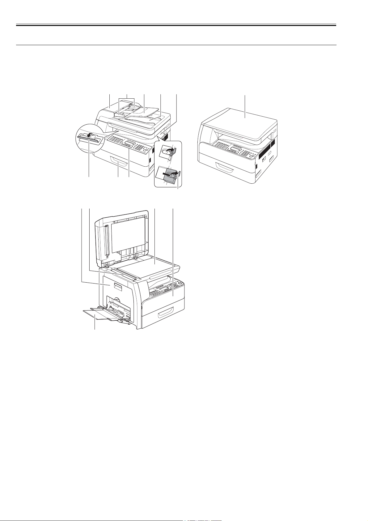
Chapter 1
1-4
1.2 Product Specifications
1.2.1 Names of Parts
1.2.1.1 External View (Front)
0013-1047
/ / / / iR1018 / iR1018J / / iR1022A / iR1022F / iR1022i / iR1022iF /
F-1-3
T-1-4
1.2.1.2 External View (Rear)
0013-1049
/ / / / iR1018 / iR1018J / / iR1022A / iR1022F / iR1022i / iR1022iF /
[1] Open/close cover [9] Cassette
[2] Slide guide [10] Stacking support
[3] Document feeder tray [11] Left cover
[4] Document delivery tray [12] Scanning glass
[5] Delivery tray [13] Orginal glass
[6] Copyboard cover [14] Front cover
[7] Paper stopper [15] Multi-purpose tray
[8] Operation panel
[1] [2] [3] [4] [5] [6]
[11][12] [13] [14]
[15]
[8][9][10]
[7]
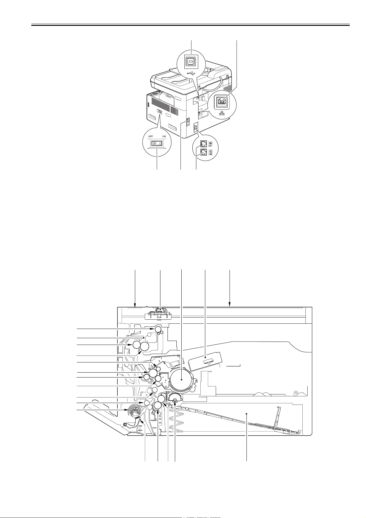
Chapter 1
1-5
F-1-4
T-1-5
1.2.1.3 Cross-Section (Main body)
0013-1050
/ / / / iR1018 / iR1018J / / iR1022A / iR1022F / iR1022i / iR1022iF /
F-1-5
[1] USB port
[2] Ethernet port*1
[3] Modular jack*2
[4] Power socket
[5] Main power switch
*1: If equipped with printer functions.
*2: If equipped with fax functions.
[1] [2]
[5] [4] [3]
[2][1]
[4]
[3]
[5]
[6][7][8][9][10]
[11]
[12]
[13]
[14]
[15]
[16]
[17]
[18]
[19]
[20]
[21]
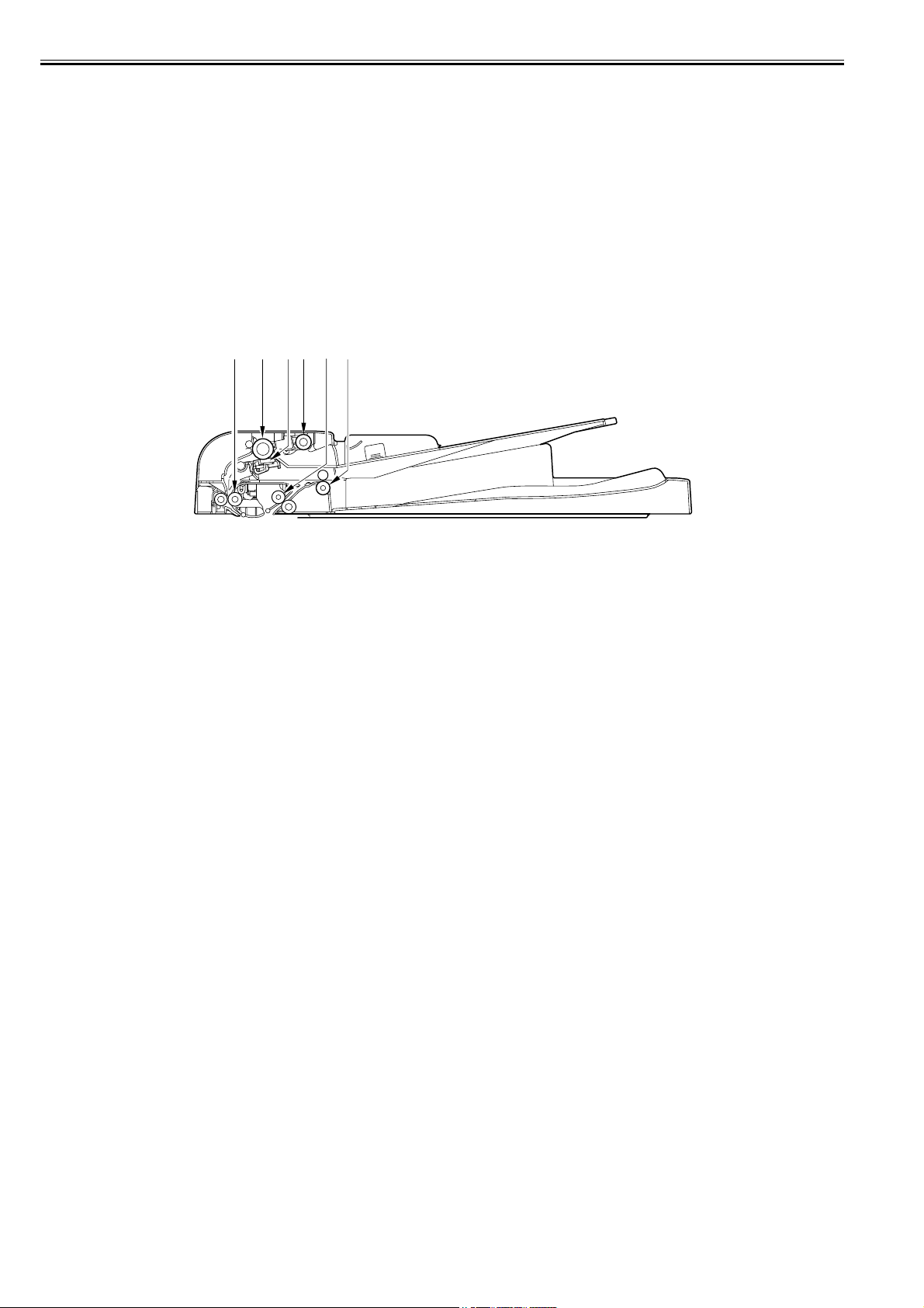
Chapter 1
1-6
T-1-6
1.2.1.4 Cross Section (ADF)
0013-1051
/ / / / iR1018 / iR1018J / / iR1022A / iR1022F / iR1022i / iR1022iF /
F-1-6
T-1-7
[1] Reading glass [12] Vertical path roller
[2] CS unit [13] Registration roller
[3] Toner bottle [14] Developing cylinder
[4] Laser scanner unit [15] Transfer charging roller
[5] Copyboard glass [16] Photopositive drum
[6] Cassette [17] Primary charging roller
[7] Pickup roller [18] Fixing film unit
[8] Feed roller [19] Fixing pressure roller
[9] Separation roller [20] Fixing unit
[10] Manual feed separation pad [21] Delivery roller
[11] Manual feed pickup roller
[1] Registration roller [4] Pickup roller
[2] Feed roller [5] Feed roller 1
[3] Separation pad [6] Delivery roller
[1] [2] [3] [4] [5] [6]
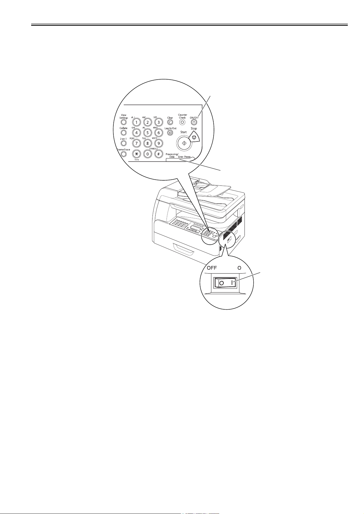
Chapter 1
1-7
1.2.2 Using the Machine
1.2.2.1 Turning On the Power Switch
0013-1052
/ / / / iR1018 / iR1018J / / iR1022A / iR1022F / iR1022i / iR1022iF /
The machine possesses 2 power switches: main power switch and control power switch. Normally (i.e., unless the machine is in a sleep state), the machine will be
supplied with power when you turn on its main power switch.
F-1-7
T-1-8
[1] Control panel power switch
[2] Main power lamp
[3] Main power switch
[3]
[1]
[2]
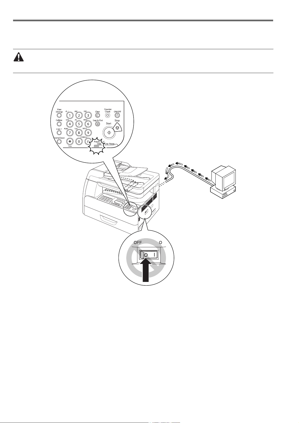
Chapter 1
1-8
1.2.2.2 When Turning Off the Main Power Switch
0013-1053
/ / / / iR1018 / iR1018J / / iR1022A / iR1022F / iR1022i / iR1022iF /
<During printing or fax data transmission/reception>
Be sure to operate the main power switch while the Processing/Data lamp on the control panel is not lit.
(Turning off the main switch during printing or fax data transmission/reception can erase the data being processed.)
F-1-8
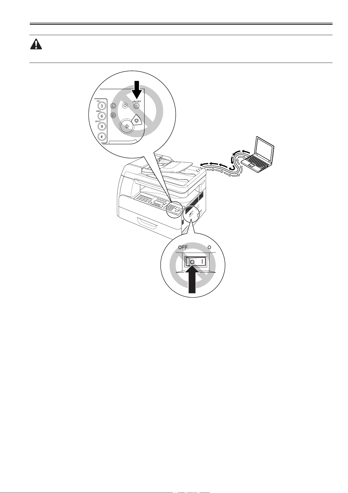
Chapter 1
1-9
<During downloading>
Do not turn off the power switch or ON/OFF switch on the control panel.
(Turning off the main power switch during downloading can make this machine inoperative.)
F-1-9
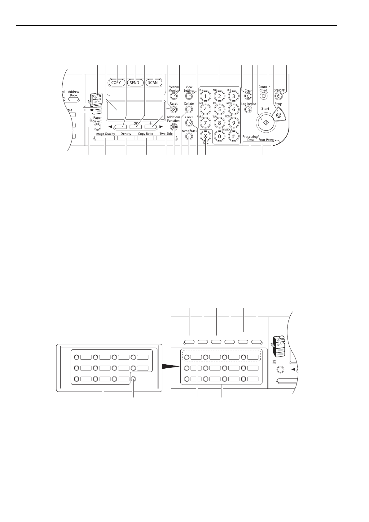
Chapter 1
1-10
1.2.2.3 Control Panel
0013-1054
/ / / / iR1018 / iR1018J / / iR1022A / iR1022F / iR1022i / iR1022iF /
F-1-10
F-1-11
[1] Paper Select indicator [17] [Counter Check] button
[2] Jam Location indicator [18] [Stop] button
[3] LCD display [19] [ON/OFF] button (operation panel power switch)
[4] [COPY] button [20] [Power] indicator
[5] [</-] button [21] [Error] indicator
[6] [SEND] button [22] [Processing/Data] indicator
[7] [OK] button [23] [Tone] button
[8] [SCAN] button [24] [2 on 1] button
[9] [>/+ ] button [25] [Frame Erase] button
[10] [Reset] button [26] [Collate] button
[11] [System Monitor] button [27] [Additional Functions] button
[12] [View Settings] button [28] [Two-Sided] button
[13] Numeric buttons [29] [Copy Ratio] button
[14] [Clear] button [30] [Density] button
[15] [log In/Out key] button [31] [Image Quality] button
[16] [Start] button [32] [Paper Select] button
[1] Direct TX key [6] Address Book key
[2] Pause key [7] Favorites buttons
[3] Hook key [8] Delayed TX key
[4] Recall key [9] Delayed TX key
[5] Coded Dial key
[31][32]
[30] [29] [28][27] [24][26] [25] [23] [22] [21] [20]
[1] [2] [4] [7][3] [5] [9][6] [8] [10] [11] [12] [13] [14] [17][18] [19][16][15]
[7][8][9][7]
Panel open
<FAX model>
13 14 15 16
17 18 19 20
21 22 23
DelayedTX
Direct TX
01 02 03 04
05 06 07 08
09 10 11 12
Address
Book
Paper
Select
CO
Image Quality
Coded
DialRecallHookPause
M4M3M2M1
[1] [2] [3] [4] [5] [6]
Loading...